1
Device Specifics Reference Manual
for DEC GKS and DEC PHIGS
Order Number: AA–QMZRA–TK
June 1995
This manual provides information on all DEC GKS™ and DEC PHIGS™
devices.
Revision/Update Information:
Digital Equipment Corporation
Maynard, Massachusetts
This revised manual supersedes the
Device Specifics Reference Manual for
DEC GKS and DEC PHIGS (Order
Number AA–Q3CEA–TK).
First Printing, January 1992
Revised, January 1994
Revised, August 1994
Revised, June 1995
Digital Equipment Corporation makes no representations that the use of its products in the
manner described in this publication will not infringe on existing or future patent rights, nor do
the descriptions contained in this publication imply the granting of licenses to make, use, or sell
equipment or software in accordance with the description.
Possession, use, or copying of the software described in this publication is authorized only pursuant
to a valid written license from Digital or an authorized sublicensor.
© Digital Equipment Corporation 1992, 1994, 1995. All Rights Reserved.
The postpaid Reader’s Comments forms at the end of this document request your critical evaluation
to assist in preparing future documentation.
The following are trademarks of Digital Equipment Corporation: DDIF, DEC, DEC Fortran,
DEC GKS, DEC GKS–3D, DEC Open3D, DEC PHIGS, DEClaser, DECnet, DECstation,
DECwindows, Digital, LA34, LA50, LA75, LA100, LA210, LA280, LA380, LA324, LJ250,
LN03 PLUS, LVP16, OpenVMS, ReGIS, VAXstation, VAXstation 2000, VAXstation 3200, VAXstation
3500, VAXstation II, VAXstation II/GPX, VAXstation II/RC, VMS, VT125, VT200, VT240, VT284,
VT286, VT330, VT340, ULTRIX, and the DIGITAL logo.
Hewlett–Packard, HP7475, HP7550, HP7580, HP7585, HP–GL, LaserJet, and PCL are registered
trademarks of Hewlett–Packard Company.
MPS–2000 is a trademark of LaserGraphics, Inc.
PostScript is a registered trademark of Adobe Systems, Incorporated.
PLOT 10, Tek, and TEKTRONIX are registered trademarks of Tektronix, Inc.
Helvetica, Palatino, and Times are registered trademarks of Linotype Company.
ITC is a trademark of International Typeface Corporation.
ITC Avant Garde Gothic, ITC Bookman, ITC Lubalin Graph, ITC Souvenir, ITC Zapf Chancery, and
ITC Zapf Dingbats are registered trademarks of International Typeface Corporation.
Motif, OSF/1, and OSF/Motif are registered trademarks of Open Software Foundation, Inc.
Peripheral Converter Module and PCM are trademarks of Spectragraphics Corporation.
UNIX is a registered trademark in the United States and other countries licensed exclusively
through X/Open Company Ltd.
OpenGL is a registered trademark of Silicon Graphics, Inc.
X Window System, Version 11, is a registered trademark of Massachusetts Institute of Technology.
ZK6193
This manual is available on CD–ROM.
This document was prepared using VAX DOCUMENT Version 2.1.
Contents
Preface . . . . . . . . . . . . . . . . . . . . . . . . . . . . . . . . . . . . . . . . . . . . . . . . . . . . . . . . . . . .
xvii
1 Introduction
1.1
1.2
1.3
1.4
1.5
1.6
1.7
1.8
1.9
1.10
1.11
1.12
1.13
1.14
1.15
1.16
Capabilities of Supported Devices . . . . . . . . . . . . . . . . . . . . . . .
Using Workstation Type Modifiers . . . . . . . . . . . . . . . . . . . . . . .
Using Constant Names for Workstation Types and Connection
Identifiers . . . . . . . . . . . . . . . . . . . . . . . . . . . . . . . . . . . . . . . . .
Supported Workstations . . . . . . . . . . . . . . . . . . . . . . . . . . . . . . .
Supported Fonts . . . . . . . . . . . . . . . . . . . . . . . . . . . . . . . . . . . . .
Predefined Bundle Table Indexes for DEC GKS . . . . . . . . . . . . .
Predefined Bundle Table Indexes for DEC PHIGS . . . . . . . . . . .
Color and Bundle Indexes . . . . . . . . . . . . . . . . . . . . . . . . . . . . .
Device-Independent HLHSR Mechanisms Support . . . . . . . . . .
Lighting Support for DEC PHIGS . . . . . . . . . . . . . . . . . . . . . . .
Depth Cueing Support for DEC PHIGS . . . . . . . . . . . . . . . . . . .
Pattern Support for DEC GKS . . . . . . . . . . . . . . . . . . . . . . . . . .
Generalized Structure Elements . . . . . . . . . . . . . . . . . . . . . . . .
Pixel Inquiries for DEC GKS . . . . . . . . . . . . . . . . . . . . . . . . . . .
Device Coordinate Information for DEC GKS and DEC PHIGS .
Environment Options . . . . . . . . . . . . . . . . . . . . . . . . . . . . . . . . .
........
........
1–1
1–2
.
.
.
.
.
.
.
.
.
.
.
.
.
.
.
.
.
.
.
.
.
.
.
.
.
.
.
.
.
.
.
.
.
.
.
.
.
.
.
.
.
.
.
.
.
.
.
.
.
.
.
.
.
.
.
.
.
.
.
.
.
.
.
.
.
.
.
.
.
.
.
.
.
.
.
.
.
.
.
.
.
.
.
.
.
.
.
.
.
.
.
.
.
.
.
.
.
.
.
.
.
.
.
.
.
.
.
.
.
.
.
.
1–2
1–2
1–6
1–6
1–8
1–10
1–11
1–12
1–12
1–12
1–13
1–13
1–13
1–14
.
.
.
.
.
.
.
.
.
.
.
.
.
.
.
.
.
.
.
.
.
.
.
.
.
.
.
.
.
.
.
.
.
.
.
.
.
.
.
.
.
.
.
.
.
.
.
.
.
.
.
.
.
.
.
.
.
.
.
.
.
.
.
.
.
.
.
.
.
.
.
.
.
.
.
.
.
.
.
.
.
.
.
.
.
.
.
.
.
.
.
.
.
.
.
.
.
.
.
.
.
.
.
.
2–1
2–1
2–2
2–3
2–4
2–5
2–7
2–8
2–13
2–13
2–14
2–14
2–15
2 CGM Output
2.1
2.2
2.3
2.4
2.5
2.6
2.7
2.8
2.9
2.10
2.11
2.12
2.13
Computer Graphics Metafiles . . . . . . . . . . . . . . . . . . . . . . . .
Environment Options . . . . . . . . . . . . . . . . . . . . . . . . . . . . . .
Valid Bit Mask Values . . . . . . . . . . . . . . . . . . . . . . . . . . . . .
Differences Between DEC GKS and DEC PHIGS, and CGM
CGM Structure . . . . . . . . . . . . . . . . . . . . . . . . . . . . . . . . . .
Character Encoding . . . . . . . . . . . . . . . . . . . . . . . . . . . . . . .
Clear Text Encoding . . . . . . . . . . . . . . . . . . . . . . . . . . . . . . .
Element Descriptions . . . . . . . . . . . . . . . . . . . . . . . . . . . . . .
Physical File Organization . . . . . . . . . . . . . . . . . . . . . . . . . .
CALS and TOP Application Profiles . . . . . . . . . . . . . . . . . . .
CALS and TOP Data Precision . . . . . . . . . . . . . . . . . . . . . .
Font Selection . . . . . . . . . . . . . . . . . . . . . . . . . . . . . . . . . . .
Encoding Examples . . . . . . . . . . . . . . . . . . . . . . . . . . . . . . .
.
.
.
.
.
.
.
.
.
.
.
.
.
.
.
.
.
.
.
.
.
.
.
.
.
.
.
.
.
.
.
.
.
.
.
.
.
.
.
iii
3 DDIF Output Workstation
.
.
.
.
.
.
.
.
.
.
.
3–1
3–1
3–2
3–2
3–3
3–4
3–4
3–5
3–6
3–7
3–9
4.1
Environment Options . . . . . . . . . . . . . . . . . . . . . . . . . . . . . . . . . . . . . . . . .
4.2
Connection Identifier . . . . . . . . . . . . . . . . . . . . . . . . . . . . . . . . . . . . . . . . .
4.3
Valid Bit Mask Values . . . . . . . . . . . . . . . . . . . . . . . . . . . . . . . . . . . . . . . .
4.4
Programming Considerations . . . . . . . . . . . . . . . . . . . . . . . . . . . . . . . . . . .
4.4.1
Display Size, Windows, and Echo Areas . . . . . . . . . . . . . . . . . . . . . . . .
4.5
Cell Array Restriction for DEC GKS . . . . . . . . . . . . . . . . . . . . . . . . . . . . .
4.6
General Information . . . . . . . . . . . . . . . . . . . . . . . . . . . . . . . . . . . . . . . . . .
4.7
Minimizing Color Traversal for DEC PHIGS . . . . . . . . . . . . . . . . . . . . . . .
4.8
Bundle Indexes . . . . . . . . . . . . . . . . . . . . . . . . . . . . . . . . . . . . . . . . . . . . .
4.9
Pattern and Hatch Values . . . . . . . . . . . . . . . . . . . . . . . . . . . . . . . . . . . . .
4.9.1
Available Fill Area Hatch Values . . . . . . . . . . . . . . . . . . . . . . . . . . . . .
4.9.2
Predefined Fill Area Pattern Values (Monochrome) for DEC GKS . . . .
4.9.3
Predefined Fill Area Pattern Values (Color) for DEC GKS . . . . . . . . . .
4.10
Input Information . . . . . . . . . . . . . . . . . . . . . . . . . . . . . . . . . . . . . . . . . . .
4.10.1
Choice Input Class . . . . . . . . . . . . . . . . . . . . . . . . . . . . . . . . . . . . . . . .
4.10.2
Locator Input Class . . . . . . . . . . . . . . . . . . . . . . . . . . . . . . . . . . . . . . .
4.10.3
Pick Input Class . . . . . . . . . . . . . . . . . . . . . . . . . . . . . . . . . . . . . . . . . .
4.10.4
String Input Class . . . . . . . . . . . . . . . . . . . . . . . . . . . . . . . . . . . . . . . .
4.10.5
Stroke Input Class . . . . . . . . . . . . . . . . . . . . . . . . . . . . . . . . . . . . . . . .
4.10.6
Valuator Input Class . . . . . . . . . . . . . . . . . . . . . . . . . . . . . . . . . . . . . .
4.11
Font Support . . . . . . . . . . . . . . . . . . . . . . . . . . . . . . . . . . . . . . . . . . . . . . .
4.11.1
Default Fonts . . . . . . . . . . . . . . . . . . . . . . . . . . . . . . . . . . . . . . . . . . . .
4.11.1.1
English and ISO–Latin–1 Fonts . . . . . . . . . . . . . . . . . . . . . . . . . . .
4.11.1.2
Japanese Fonts . . . . . . . . . . . . . . . . . . . . . . . . . . . . . . . . . . . . . . .
4.11.1.3
Hebrew and ISO–Latin–8 Fonts . . . . . . . . . . . . . . . . . . . . . . . . . .
Font Mode Options . . . . . . . . . . . . . . . . . . . . . . . . . . . . . . . . . . . . . . . .
4.11.2
4.11.3
Known Fonts . . . . . . . . . . . . . . . . . . . . . . . . . . . . . . . . . . . . . . . . . . . .
4.12
UIL Files . . . . . . . . . . . . . . . . . . . . . . . . . . . . . . . . . . . . . . . . . . . . . . . . . .
4.13
Customization . . . . . . . . . . . . . . . . . . . . . . . . . . . . . . . . . . . . . . . . . . . . . .
4.13.1
Use of Xdefaults Files . . . . . . . . . . . . . . . . . . . . . . . . . . . . . . . . . . . . .
4.13.2
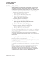
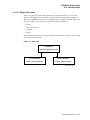
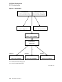
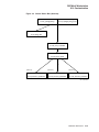
Widget Hierarchies . . . . . . . . . . . . . . . . . . . . . . . . . . . . . . . . . . . . . . .
4.14
Internationalization . . . . . . . . . . . . . . . . . . . . . . . . . . . . . . . . . . . . . . . . . .
4.15
DEC GKS Sample Application . . . . . . . . . . . . . . . . . . . . . . . . . . . . . . . . . .
4–1
4–8
4–9
4–11
4–12
4–12
4–12
4–13
4–13
4–13
4–13
4–14
4–14
4–16
4–16
4–17
4–18
4–18
4–19
4–20
4–20
4–20
4–21
4–21
4–22
4–22
4–23
4–25
4–26
4–26
4–28
4–32
4–32
3.1
3.2
3.3
3.4
3.5
3.6
3.6.1
3.7
3.7.1
3.7.2
3.8
Copying DDIF Files from UNIX Systems to OpenVMS Systems
DDIF Output . . . . . . . . . . . . . . . . . . . . . . . . . . . . . . . . . . . . . . .
Environment Options . . . . . . . . . . . . . . . . . . . . . . . . . . . . . . . . .
Valid Bit Mask Values . . . . . . . . . . . . . . . . . . . . . . . . . . . . . . . .
Differences Between DEC GKS and DEC PHIGS, and DDIF . .
Color Capabilities . . . . . . . . . . . . . . . . . . . . . . . . . . . . . . . . . . . .
Color Reservation . . . . . . . . . . . . . . . . . . . . . . . . . . . . . . . . .
Pattern and Hatch Values . . . . . . . . . . . . . . . . . . . . . . . . . . . . .
Available Fill Area Hatch Values . . . . . . . . . . . . . . . . . . . . .
Predefined Fill Area Pattern Values for DEC GKS . . . . . . .
Japanese Fonts . . . . . . . . . . . . . . . . . . . . . . . . . . . . . . . . . . . . .
.
.
.
.
.
.
.
.
.
.
.
.
.
.
.
.
.
.
.
.
.
.
.
.
.
.
.
.
.
.
.
.
.
.
.
.
.
.
.
.
.
.
.
.
.
.
.
.
.
.
.
.
.
.
.
.
.
.
.
.
.
.
.
.
.
.
.
.
.
.
.
.
.
.
.
.
.
4 DECwindows Workstation
iv
5 HPPCL Workstation
5.1
5.2
5.2.1
5.3
5.4
5.5
Environment Options . . . . . . . . . .
Valid Bit Mask Values . . . . . . . . .
Device Queues and Allocation
Printer Resolutions . . . . . . . . . . .
File Format . . . . . . . . . . . . . . . . .
Performance Notes . . . . . . . . . . . .
.
.
.
.
.
.
.
.
.
.
.
.
.
.
.
.
.
.
.
.
.
.
.
.
.
.
.
.
.
.
.
.
.
.
.
.
.
.
.
.
.
.
.
.
.
.
.
.
.
.
.
.
.
.
.
.
.
.
.
.
.
.
.
.
.
.
.
.
.
.
.
.
.
.
.
.
.
.
.
.
.
.
.
.
.
.
.
.
.
.
.
.
.
.
.
.
.
.
.
.
.
.
.
.
.
.
.
.
.
.
.
.
.
.
.
.
.
.
.
.
.
.
.
.
.
.
.
.
.
.
.
.
.
.
.
.
.
.
.
.
.
.
.
.
.
.
.
.
.
.
.
.
.
.
.
.
.
.
.
.
.
.
.
.
.
.
.
.
.
.
.
.
.
.
.
.
.
.
.
.
.
.
.
.
.
.
5–1
5–2
5–2
5–3
5–3
5–3
Environment Options . . . . . . . . . . . . . . . . . . . . . . . . . .
Valid Bit Mask Values . . . . . . . . . . . . . . . . . . . . . . . . .
Device Queues and Allocation . . . . . . . . . . . . . . . . . . .
Pattern and Hatch Values . . . . . . . . . . . . . . . . . . . . . .
Available Fill Area Hatch Values . . . . . . . . . . . . . .
Predefined Fill Area Pattern Values for DEC GKS
.
.
.
.
.
.
.
.
.
.
.
.
.
.
.
.
.
.
.
.
.
.
.
.
.
.
.
.
.
.
.
.
.
.
.
.
.
.
.
.
.
.
.
.
.
.
.
.
.
.
.
.
.
.
.
.
.
.
.
.
.
.
.
.
.
.
.
.
.
.
.
.
.
.
.
.
.
.
.
.
.
.
.
.
.
.
.
.
.
.
6–1
6–2
6–2
6–3
6–3
6–3
.
.
.
.
.
.
.
.
.
.
.
.
.
.
.
.
.
.
.
.
.
.
.
.
.
.
.
.
.
.
.
.
.
.
.
.
.
.
.
.
.
.
.
.
.
.
.
.
.
.
.
.
.
.
.
.
.
.
.
.
.
.
.
.
.
.
.
.
.
.
.
.
.
.
.
.
.
.
.
.
.
.
.
.
.
.
.
.
.
.
7–1
7–2
7–3
7–4
7–4
7–5
.
.
.
.
.
.
.
.
.
.
.
.
.
.
.
.
.
.
.
.
.
.
.
.
.
.
.
.
.
.
.
.
.
.
.
.
.
.
.
.
.
.
.
.
.
.
.
.
.
.
.
.
.
.
.
.
.
.
.
.
.
.
.
.
.
.
.
.
.
.
.
.
.
.
.
.
.
.
.
.
.
.
.
.
.
.
.
.
.
.
.
.
.
.
.
.
.
.
.
.
.
.
.
.
.
.
.
.
.
.
.
.
.
.
.
.
.
.
.
.
.
.
.
.
.
.
.
.
.
.
.
.
.
.
.
8–1
8–2
8–4
8–4
8–4
8–5
8–5
8–5
8–5
Environment Options . . . . . . . . . . . . . . . . . . . . . . . . . . . . . . . . . . . . .
Connection Identifier . . . . . . . . . . . . . . . . . . . . . . . . . . . . . . . . . . . . .
Valid Bit Mask Values . . . . . . . . . . . . . . . . . . . . . . . . . . . . . . . . . . . .
Programming Considerations . . . . . . . . . . . . . . . . . . . . . . . . . . . . . . .
Display Size, Windows, and Echo Areas . . . . . . . . . . . . . . . . . . . .
Overlay Plane Support . . . . . . . . . . . . . . . . . . . . . . . . . . . . . . . . . . . .
Cell Array Restriction for DEC GKS . . . . . . . . . . . . . . . . . . . . . . . . .
General Information . . . . . . . . . . . . . . . . . . . . . . . . . . . . . . . . . . . . . .
Minimizing Color Traversal for DEC PHIGS . . . . . . . . . . . . . . . . . . .
Bundle Indexes . . . . . . . . . . . . . . . . . . . . . . . . . . . . . . . . . . . . . . . . .
Pattern and Hatch Values . . . . . . . . . . . . . . . . . . . . . . . . . . . . . . . . .
Available Fill Area Hatch Values . . . . . . . . . . . . . . . . . . . . . . . . .
Predefined Fill Area Pattern Values (Monochrome) for DEC GKS
Predefined Fill Area Pattern Values (Color) for DEC GKS . . . . . .
.
.
.
.
.
.
.
.
.
.
.
.
.
.
.
.
.
.
.
.
.
.
.
.
.
.
.
.
.
.
.
.
.
.
.
.
.
.
.
.
.
.
.
.
.
.
.
.
.
.
.
.
.
.
.
.
9–1
9–7
9–8
9–11
9–11
9–11
9–12
9–12
9–12
9–13
9–13
9–13
9–14
9–14
6 LCG01 Workstation
6.1
6.2
6.3
6.4
6.4.1
6.4.2
7 LJ250 and LA324 Workstation
7.1
7.2
7.3
7.4
7.4.1
7.4.2
Environment Options . . . . . . . . . . . . . . . . . . . . . . . . . .
Valid Bit Mask Values . . . . . . . . . . . . . . . . . . . . . . . . .
Device Considerations . . . . . . . . . . . . . . . . . . . . . . . . .
Pattern and Hatch Values . . . . . . . . . . . . . . . . . . . . . .
Available Fill Area Hatch Values . . . . . . . . . . . . . .
Predefined Fill Area Pattern Values for DEC GKS
8 LVP16 and HP–GL Graphics Protocol Workstation
8.1
8.2
8.3
8.3.1
8.3.2
8.4
8.4.1
8.4.2
8.5
Environment Options . . . . . . . . . . . . . . . . . . . . . . . . . .
Valid Bit Mask Values . . . . . . . . . . . . . . . . . . . . . . . . .
Device Considerations . . . . . . . . . . . . . . . . . . . . . . . . .
LVP16 Switch Settings . . . . . . . . . . . . . . . . . . . . . .
Device Queues and Allocation . . . . . . . . . . . . . . . .
Pattern and Hatch Values . . . . . . . . . . . . . . . . . . . . . .
Available Fill Area Hatch Values . . . . . . . . . . . . . .
Predefined Fill Area Pattern Values for DEC GKS
LVP16 Font Support and Font Samples . . . . . . . . . . . .
9 OSF/Motif Workstation
9.1
9.2
9.3
9.4
9.4.1
9.5
9.6
9.7
9.8
9.9
9.10
9.10.1
9.10.2
9.10.3
v
9.11
Input Information . . . . . . . . . . . . . . . . . . . . . . . . . . . . . . . . . . . . . . . . . . .
9.11.1
Choice Input Class . . . . . . . . . . . . . . . . . . . . . . . . . . . . . . . . . . . . . . . .
9.11.2
Locator Input Class . . . . . . . . . . . . . . . . . . . . . . . . . . . . . . . . . . . . . . .
9.11.3
Pick Input Class . . . . . . . . . . . . . . . . . . . . . . . . . . . . . . . . . . . . . . . . . .
9.11.4
String Input Class . . . . . . . . . . . . . . . . . . . . . . . . . . . . . . . . . . . . . . . .
9.11.5
Stroke Input Class . . . . . . . . . . . . . . . . . . . . . . . . . . . . . . . . . . . . . . . .
9.11.6
Valuator Input Class . . . . . . . . . . . . . . . . . . . . . . . . . . . . . . . . . . . . . .
9.12
Font Support . . . . . . . . . . . . . . . . . . . . . . . . . . . . . . . . . . . . . . . . . . . . . . .
9.12.1
Default Fonts . . . . . . . . . . . . . . . . . . . . . . . . . . . . . . . . . . . . . . . . . . . .
9.12.1.1
English and ISO–Latin–1 Fonts . . . . . . . . . . . . . . . . . . . . . . . . . . .
9.12.1.2
Japanese Fonts . . . . . . . . . . . . . . . . . . . . . . . . . . . . . . . . . . . . . . .
9.12.1.3
Hebrew and ISO–Latin–8 Fonts . . . . . . . . . . . . . . . . . . . . . . . . . .
9.12.2
Font Mode Options . . . . . . . . . . . . . . . . . . . . . . . . . . . . . . . . . . . . . . . .
9.12.3
Known Fonts . . . . . . . . . . . . . . . . . . . . . . . . . . . . . . . . . . . . . . . . . . . .
9.13
UIL Files . . . . . . . . . . . . . . . . . . . . . . . . . . . . . . . . . . . . . . . . . . . . . . . . . .
9.14
Customization . . . . . . . . . . . . . . . . . . . . . . . . . . . . . . . . . . . . . . . . . . . . . .
9.14.1
Use of Xdefaults Files . . . . . . . . . . . . . . . . . . . . . . . . . . . . . . . . . . . . .
9.14.2
Widget Hierarchies . . . . . . . . . . . . . . . . . . . . . . . . . . . . . . . . . . . . . . .
9.15
Internationalization . . . . . . . . . . . . . . . . . . . . . . . . . . . . . . . . . . . . . . . . . .
9.16
DEC GKS Sample Application . . . . . . . . . . . . . . . . . . . . . . . . . . . . . . . . . .
9–15
9–16
9–17
9–17
9–18
9–19
9–19
9–20
9–20
9–20
9–21
9–21
9–22
9–23
9–25
9–25
9–26
9–27
9–31
9–31
10 OpenGL Workstation
.
.
.
.
.
.
.
.
.
.
.
.
10–1
10–8
10–9
10–9
10–9
10–11
10–12
10–12
10–12
10–12
10–12
10–13
11.1
Environment Options . . . . . . . . . . . . . . . . . . . . . . . . . . . . . . . . . . . . . . . . .
11.2
Connection Identifier . . . . . . . . . . . . . . . . . . . . . . . . . . . . . . . . . . . . . . . . .
11.2.1
HLHSR Mechanism Support for PEX Devices . . . . . . . . . . . . . . . . . . .
11.2.2
Anti-Aliasing Modes . . . . . . . . . . . . . . . . . . . . . . . . . . . . . . . . . . . . . . .
11.2.2.1
PXG Accelerators . . . . . . . . . . . . . . . . . . . . . . . . . . . . . . . . . . . . . .
11.2.2.2
VAXstation SPXg and SPXgt Accelerators . . . . . . . . . . . . . . . . . . .
11.2.2.3
SFB+ Accelerators . . . . . . . . . . . . . . . . . . . . . . . . . . . . . . . . . . . . .
11.2.2.4
ZLX Accelerators . . . . . . . . . . . . . . . . . . . . . . . . . . . . . . . . . . . . . .
11.3
Workstation Type Values . . . . . . . . . . . . . . . . . . . . . . . . . . . . . . . . . . . . . .
11.3.1
Opening Multiple Motif Workstations . . . . . . . . . . . . . . . . . . . . . . . . .
11.4
Programming Considerations . . . . . . . . . . . . . . . . . . . . . . . . . . . . . . . . . . .
11.4.1
General Information . . . . . . . . . . . . . . . . . . . . . . . . . . . . . . . . . . . . . . .
11.5
Input Information . . . . . . . . . . . . . . . . . . . . . . . . . . . . . . . . . . . . . . . . . . .
11.6
Lighting Support for DEC PHIGS . . . . . . . . . . . . . . . . . . . . . . . . . . . . . . .
11.7
Font Support . . . . . . . . . . . . . . . . . . . . . . . . . . . . . . . . . . . . . . . . . . . . . . .
11.8
Escapes . . . . . . . . . . . . . . . . . . . . . . . . . . . . . . . . . . . . . . . . . . . . . . . . . . .
11–1
11–9
11–10
11–10
11–10
11–11
11–12
11–13
11–13
11–15
11–15
11–15
11–15
11–15
11–16
11–16
10.1
10.2
10.2.1
10.2.2
10.3
10.4
10.4.1
10.5
10.6
10.7
10.8
10.9
Environment Options . . . . . . . . . . . . . . . . . . . . . . . . .
Connection Identifier . . . . . . . . . . . . . . . . . . . . . . . . .
HLHSR Mechanism Support for OpenGL Devices
Anti-Aliasing Modes . . . . . . . . . . . . . . . . . . . . . . .
Workstation Type Values . . . . . . . . . . . . . . . . . . . . . .
Programming Considerations . . . . . . . . . . . . . . . . . . .
General Information . . . . . . . . . . . . . . . . . . . . . . .
Input Information . . . . . . . . . . . . . . . . . . . . . . . . . . .
Font Support . . . . . . . . . . . . . . . . . . . . . . . . . . . . . . .
Escapes . . . . . . . . . . . . . . . . . . . . . . . . . . . . . . . . . . .
Limitations . . . . . . . . . . . . . . . . . . . . . . . . . . . . . . . .
Examples . . . . . . . . . . . . . . . . . . . . . . . . . . . . . . . . . .
.
.
.
.
.
.
.
.
.
.
.
.
.
.
.
.
.
.
.
.
.
.
.
.
.
.
.
.
.
.
.
.
.
.
.
.
.
.
.
.
.
.
.
.
.
.
.
.
.
.
.
.
.
.
.
.
.
.
.
.
.
.
.
.
.
.
.
.
.
.
.
.
.
.
.
.
.
.
.
.
.
.
.
.
.
.
.
.
.
.
.
.
.
.
.
.
.
.
.
.
.
.
.
.
.
.
.
.
.
.
.
.
.
.
.
.
.
.
.
.
.
.
.
.
.
.
.
.
.
.
.
.
.
.
.
.
.
.
.
.
.
.
.
.
.
.
.
.
.
.
.
.
.
.
.
.
.
.
.
.
.
.
.
.
.
.
.
.
.
.
.
.
.
.
.
.
.
.
.
.
11 PEX Workstation
vi
12 PostScript Workstation
12.1
12.2
12.3
12.4
12.4.1
12.4.2
12.5
12.5.1
12.5.2
12.6
12.7
Environment Options . . . . . . . . . . . . . . . . . . . . . . . . . .
Valid Bit Mask Values . . . . . . . . . . . . . . . . . . . . . . . . .
Encapsulated PostScript . . . . . . . . . . . . . . . . . . . . . . .
Device Considerations . . . . . . . . . . . . . . . . . . . . . . . . .
Device Queues and Allocation . . . . . . . . . . . . . . . .
Printer Description Files . . . . . . . . . . . . . . . . . . . .
Pattern and Hatch Values . . . . . . . . . . . . . . . . . . . . . .
Available Fill Area Hatch Values . . . . . . . . . . . . . .
Predefined Fill Area Pattern Values for DEC GKS
Font Support . . . . . . . . . . . . . . . . . . . . . . . . . . . . . . . .
ISO–Latin1 Character Support . . . . . . . . . . . . . . . . . .
.
.
.
.
.
.
.
.
.
.
.
.
.
.
.
.
.
.
.
.
.
.
.
.
.
.
.
.
.
.
.
.
.
.
.
.
.
.
.
.
.
.
.
.
.
.
.
.
.
.
.
.
.
.
.
.
.
.
.
.
.
.
.
.
.
.
.
.
.
.
.
.
.
.
.
.
.
.
.
.
.
.
.
.
.
.
.
.
.
.
.
.
.
.
.
.
.
.
.
.
.
.
.
.
.
.
.
.
.
.
.
.
.
.
.
.
.
.
.
.
.
.
.
.
.
.
.
.
.
.
.
.
.
.
.
.
.
.
.
.
.
.
.
.
.
.
.
.
.
.
.
.
.
.
.
.
.
.
.
.
.
.
.
.
.
12–1
12–2
12–3
12–4
12–4
12–4
12–5
12–5
12–6
12–6
12–8
Environment Options . . . . . . . . . . . . . . . . . . . . . . . . . . . .
Valid Bit Mask Values . . . . . . . . . . . . . . . . . . . . . . . . . . .
ReGIS Bit Masks . . . . . . . . . . . . . . . . . . . . . . . . . . . .
ReGIS Output to a File . . . . . . . . . . . . . . . . . . . . . . .
Bit Mask for the VT340 to Restore the Color Map . . .
Mode Restrictions . . . . . . . . . . . . . . . . . . . . . . . . . . . . . .
Pattern and Hatch Values . . . . . . . . . . . . . . . . . . . . . . . .
Available Fill Area Hatch Values . . . . . . . . . . . . . . . .
Predefined Fill Area Pattern Values for DEC GKS . .
Input Information . . . . . . . . . . . . . . . . . . . . . . . . . . . . . .
Choice Input Class . . . . . . . . . . . . . . . . . . . . . . . . . . .
Locator Input Class . . . . . . . . . . . . . . . . . . . . . . . . . .
Pick Input Class . . . . . . . . . . . . . . . . . . . . . . . . . . . . .
String Input Class . . . . . . . . . . . . . . . . . . . . . . . . . . .
Stroke Input Class . . . . . . . . . . . . . . . . . . . . . . . . . . .
Valuator Input Class . . . . . . . . . . . . . . . . . . . . . . . . .
.
.
.
.
.
.
.
.
.
.
.
.
.
.
.
.
.
.
.
.
.
.
.
.
.
.
.
.
.
.
.
.
.
.
.
.
.
.
.
.
.
.
.
.
.
.
.
.
.
.
.
.
.
.
.
.
.
.
.
.
.
.
.
.
.
.
.
.
.
.
.
.
.
.
.
.
.
.
.
.
.
.
.
.
.
.
.
.
.
.
.
.
.
.
.
.
.
.
.
.
.
.
.
.
.
.
.
.
.
.
.
.
.
.
.
.
.
.
.
.
.
.
.
.
.
.
.
.
.
.
.
.
.
.
.
.
.
.
.
.
.
.
.
.
.
.
.
.
.
.
.
.
.
.
.
.
.
.
.
.
.
.
.
.
.
.
.
.
.
.
.
.
.
.
.
.
.
.
.
.
.
.
.
.
.
.
.
.
.
.
.
.
.
.
.
.
.
.
.
.
.
.
.
.
.
.
.
.
13–1
13–2
13–2
13–2
13–3
13–4
13–4
13–4
13–4
13–5
13–5
13–6
13–7
13–8
13–8
13–9
......
......
14–1
14–2
......
14–2
.
.
.
.
.
.
.
.
14–3
14–4
14–4
14–4
14–5
14–5
14–5
14–7
13 ReGIS™ Graphics Protocol Workstation
13.1
13.2
13.2.1
13.2.2
13.2.3
13.3
13.4
13.4.1
13.4.2
13.5
13.5.1
13.5.2
13.5.3
13.5.4
13.5.5
13.5.6
14 Sixel Graphics Protocol Workstation
14.1
Environment Options . . . . . . . . . . . . . . . . . . . . . . . . . . . . . . . . . . .
14.2
Valid Bit Mask Values . . . . . . . . . . . . . . . . . . . . . . . . . . . . . . . . . .
14.2.1
LA50, LA75, LA84, LA86, LA100, LA210, LA280, and LA380
Graphics Handlers . . . . . . . . . . . . . . . . . . . . . . . . . . . . . . . . . .
14.2.2
LN03 PLUS, LN03_J PLUS, and DEClaser (LN06) Graphics
Handlers . . . . . . . . . . . . . . . . . . . . . . . . . . . . . . . . . . . . . . . . .
14.3
Device Considerations . . . . . . . . . . . . . . . . . . . . . . . . . . . . . . . . . .
14.3.1
LA50 Switch Settings . . . . . . . . . . . . . . . . . . . . . . . . . . . . . . . .
14.3.2
Device Queues and Allocation . . . . . . . . . . . . . . . . . . . . . . . . .
14.4
Pattern and Hatch Values . . . . . . . . . . . . . . . . . . . . . . . . . . . . . . .
14.4.1
Available Fill Area Hatch Values . . . . . . . . . . . . . . . . . . . . . . .
14.4.2
Predefined Fill Area Pattern Values for DEC GKS . . . . . . . . .
14.5
Printer Resolutions . . . . . . . . . . . . . . . . . . . . . . . . . . . . . . . . . . . .
.
.
.
.
.
.
.
.
.
.
.
.
.
.
.
.
.
.
.
.
.
.
.
.
.
.
.
.
.
.
.
.
.
.
.
.
.
.
.
.
vii
15 Tektronix 4014 Workstation
15.1
15.2
15.3
15.3.1
15.3.2
15.4
15.4.1
15.5
15.5.1
15.5.2
15.5.3
15.5.4
15.5.5
15.5.6
Environment Options . . . . . . . . . . . .
Valid Bit Mask Values . . . . . . . . . . .
Programming Considerations . . . . . .
Echo of Characters . . . . . . . . . . .
GIN Mode Configuration . . . . . .
Pattern and Hatch Values . . . . . . . .
Available Fill Area Hatch Values
Input Information . . . . . . . . . . . . . .
Choice Input Class . . . . . . . . . . .
Locator Input Class . . . . . . . . . .
Pick Input Class . . . . . . . . . . . . .
String Input Class . . . . . . . . . . .
Stroke Input Class . . . . . . . . . . .
Valuator Input Class . . . . . . . . .
.
.
.
.
.
.
.
.
.
.
.
.
.
.
.
.
.
.
.
.
.
.
.
.
.
.
.
.
.
.
.
.
.
.
.
.
.
.
.
.
.
.
.
.
.
.
.
.
.
.
.
.
.
.
.
.
.
.
.
.
.
.
.
.
.
.
.
.
.
.
.
.
.
.
.
.
.
.
.
.
.
.
.
.
.
.
.
.
.
.
.
.
.
.
.
.
.
.
.
.
.
.
.
.
.
.
.
.
.
.
.
.
.
.
.
.
.
.
.
.
.
.
.
.
.
.
.
.
.
.
.
.
.
.
.
.
.
.
.
.
.
.
.
.
.
.
.
.
.
.
.
.
.
.
.
.
.
.
.
.
.
.
.
.
.
.
.
.
.
.
.
.
.
.
.
.
.
.
.
.
.
.
.
.
.
.
.
.
.
.
.
.
.
.
.
.
.
.
.
.
.
.
.
.
.
.
.
.
.
.
.
.
.
.
.
.
.
.
.
.
.
.
.
.
.
.
.
.
.
.
.
.
.
.
.
.
.
.
.
.
.
.
.
.
.
.
.
.
.
.
.
.
.
.
.
.
.
.
.
.
.
.
.
.
.
.
.
.
.
.
.
.
.
.
.
.
.
.
.
.
.
.
.
.
.
.
.
.
.
.
.
.
.
.
.
.
.
.
.
.
.
.
.
.
.
.
.
.
.
.
.
.
.
.
.
.
.
.
.
.
.
.
.
.
.
.
.
.
.
.
.
.
.
.
.
.
.
.
.
.
.
.
.
.
.
.
.
.
.
.
.
.
.
.
.
.
.
.
.
.
.
.
.
.
.
.
.
.
.
.
.
.
.
.
.
.
.
.
.
.
.
.
.
.
.
.
.
.
.
.
.
.
.
.
.
.
.
.
.
.
.
.
.
.
.
.
15–1
15–2
15–3
15–3
15–3
15–4
15–4
15–5
15–5
15–5
15–6
15–7
15–7
15–8
Environment Options . . . . . . . . . . . . . . . . . . . . . . . . . . . . . . . . . . . . . . . . .
Valid Bit Mask Values . . . . . . . . . . . . . . . . . . . . . . . . . . . . . . . . . . . . . . . .
Programming Considerations . . . . . . . . . . . . . . . . . . . . . . . . . . . . . . . . . . .
Setup Requirement . . . . . . . . . . . . . . . . . . . . . . . . . . . . . . . . . . . . . . .
Resetting the Terminal After an Interrupt . . . . . . . . . . . . . . . . . . . . . .
Tektronix 4107 and 4207 Pattern and Hatch Values . . . . . . . . . . . . . . . . .
Available Fill Area Hatch Values . . . . . . . . . . . . . . . . . . . . . . . . . . . . .
Predefined Fill Area Pattern Values for DEC GKS . . . . . . . . . . . . . . .
Input Information . . . . . . . . . . . . . . . . . . . . . . . . . . . . . . . . . . . . . . . . . . .
How to Use Additional Physical Devices . . . . . . . . . . . . . . . . . . . . . . .
Using Logical Device Mappings . . . . . . . . . . . . . . . . . . . . . . . . . . . . . .
Choice Input Class . . . . . . . . . . . . . . . . . . . . . . . . . . . . . . . . . . . . . . . .
Locator Input Class . . . . . . . . . . . . . . . . . . . . . . . . . . . . . . . . . . . . . . .
Pick Input Class . . . . . . . . . . . . . . . . . . . . . . . . . . . . . . . . . . . . . . . . . .
String Input Class . . . . . . . . . . . . . . . . . . . . . . . . . . . . . . . . . . . . . . . .
Stroke Input Class . . . . . . . . . . . . . . . . . . . . . . . . . . . . . . . . . . . . . . . .
Valuator Input Class . . . . . . . . . . . . . . . . . . . . . . . . . . . . . . . . . . . . . .
16–1
16–3
16–3
16–4
16–4
16–5
16–5
16–5
16–6
16–6
16–7
16–9
16–9
16–10
16–11
16–12
16–13
16 Tektronix 4100, 4200, and VS500 Series Workstations
16.1
16.2
16.3
16.3.1
16.3.2
16.4
16.4.1
16.4.2
16.5
16.5.1
16.5.2
16.5.3
16.5.4
16.5.5
16.5.6
16.5.7
16.5.8
17 VWS Workstation
17.1
17.2
17.3
17.3.1
17.3.2
17.4
17.5
17.5.1
17.5.2
17.5.3
17.6
17.6.1
17.6.2
17.6.3
17.6.4
17.6.5
viii
Environment Options . . . . . . . . . . . . . . . . . . . . . . . . . . . . . . . . . . . . .
Valid Bit Mask Values . . . . . . . . . . . . . . . . . . . . . . . . . . . . . . . . . . . .
Device Considerations . . . . . . . . . . . . . . . . . . . . . . . . . . . . . . . . . . . .
Display Size, Windows, and Echo Areas . . . . . . . . . . . . . . . . . . . .
Additional Information . . . . . . . . . . . . . . . . . . . . . . . . . . . . . . . . .
Cell Array Restriction for DEC GKS . . . . . . . . . . . . . . . . . . . . . . . . .
Pattern and Hatch Values . . . . . . . . . . . . . . . . . . . . . . . . . . . . . . . . .
Available Fill Area Hatch Values . . . . . . . . . . . . . . . . . . . . . . . . .
Predefined Fill Area Pattern Values (Monochrome) for DEC GKS
Predefined Fill Area Pattern Values (Color) for DEC GKS . . . . . .
Input Information . . . . . . . . . . . . . . . . . . . . . . . . . . . . . . . . . . . . . . .
Choice Input Class . . . . . . . . . . . . . . . . . . . . . . . . . . . . . . . . . . . .
Locator Input Class . . . . . . . . . . . . . . . . . . . . . . . . . . . . . . . . . . .
Pick Input Class . . . . . . . . . . . . . . . . . . . . . . . . . . . . . . . . . . . . . .
String Input Class . . . . . . . . . . . . . . . . . . . . . . . . . . . . . . . . . . . .
Stroke Input Class . . . . . . . . . . . . . . . . . . . . . . . . . . . . . . . . . . . .
.
.
.
.
.
.
.
.
.
.
.
.
.
.
.
.
.
.
.
.
.
.
.
.
.
.
.
.
.
.
.
.
.
.
.
.
.
.
.
.
.
.
.
.
.
.
.
.
.
.
.
.
.
.
.
.
.
.
.
.
.
.
.
.
17–1
17–2
17–4
17–4
17–6
17–7
17–7
17–8
17–9
17–9
17–12
17–12
17–13
17–13
17–14
17–15
17.6.6
Valuator Input Class . . . . . . . . . . . . . . . . . . . . . . . . . . . . . . . . . . . . . .
17.7
Font Support . . . . . . . . . . . . . . . . . . . . . . . . . . . . . . . . . . . . . . . . . . . . . . .
17–15
17–16
A Device-Independent Fonts
A.1
A.2
A.3
A.4
A.4.1
A.4.2
A.5
A.5.1
A.5.2
A.6
Device-Independent Fonts . . . . . . . . .
Font File Formats . . . . . . . . . . . . . . .
Font Design . . . . . . . . . . . . . . . . . . . .
Stroke Font File . . . . . . . . . . . . . . . . .
Stroke Font File Header . . . . . . .
Character Descriptor . . . . . . . . . .
Stroke Font Environment Support . . .
Stroke Font Path . . . . . . . . . . . . .
Stroke Font List and Stroke Font
Device-Independent Fonts . . . . . . . . .
.
.
.
.
.
.
.
.
.
.
.
.
.
.
.
.
.
.
.
.
.
.
.
.
.
.
.
.
.
.
.
.
.
.
.
.
.
.
.
.
.
.
.
.
.
.
.
.
.
.
.
.
.
.
.
.
.
.
.
.
.
.
.
.
.
.
.
.
.
.
.
.
.
.
.
.
.
.
.
.
.
.
.
.
.
.
.
.
.
.
.
.
.
.
.
.
.
.
.
.
.
.
.
.
.
.
.
.
.
.
.
.
.
.
.
.
.
.
.
.
.
.
.
.
.
.
.
.
.
.
.
.
.
.
.
.
.
.
.
.
.
.
.
.
.
.
.
.
.
.
.
.
.
.
.
.
.
.
.
.
.
.
.
.
.
.
.
.
.
.
.
.
.
.
.
.
.
.
.
.
.
.
.
.
.
.
.
.
.
.
.
.
.
.
.
.
.
.
.
.
.
.
.
.
.
.
.
.
.
.
.
.
.
.
.
.
.
.
.
.
.
.
.
.
.
.
.
.
.
.
.
.
.
.
.
.
.
.
.
.
.
.
.
.
.
.
.
.
.
.
.
.
.
.
.
.
.
.
.
.
.
.
.
.
.
.
.
.
.
.
.
.
.
.
.
.
.
.
.
.
A–1
A–1
A–2
A–3
A–4
A–6
A–7
A–7
A–7
A–7
Escape Function Changes . . . . . . . . . . . . . . . . . . . . . . . . . . . . .
New Escape Record Definitions . . . . . . . . . . . . . . . . . . . . . .
List of Escape Identifiers . . . . . . . . . . . . . . . . . . . . . . . . . . . . . .
Escape Syntax . . . . . . . . . . . . . . . . . . . . . . . . . . . . . . . . . . . . . .
–100 Set Display Speed . . . . . . . . . . . . . . . . . . . . . . . . . . . .
–101 Generate Hardcopy of Workstation Surface . . . . . . . . .
–103 Beep . . . . . . . . . . . . . . . . . . . . . . . . . . . . . . . . . . . . . .
–106 Pop Workstation . . . . . . . . . . . . . . . . . . . . . . . . . . . . .
–107 Push Workstation . . . . . . . . . . . . . . . . . . . . . . . . . . . .
–108 Set Error Handling Mode . . . . . . . . . . . . . . . . . . . . . .
–109 Set Viewport Event . . . . . . . . . . . . . . . . . . . . . . . . . . .
–110 Associate Workstation Type and Connection Identifier
–111 Software Clipping . . . . . . . . . . . . . . . . . . . . . . . . . . . .
–150 Set Writing Mode . . . . . . . . . . . . . . . . . . . . . . . . . . . . .
–151 Set Line Cap Style . . . . . . . . . . . . . . . . . . . . . . . . . . . .
–152 Set Line Join Style . . . . . . . . . . . . . . . . . . . . . . . . . . .
–153 Set Edge Control Flag . . . . . . . . . . . . . . . . . . . . . . . . .
–154 Set Edge Type . . . . . . . . . . . . . . . . . . . . . . . . . . . . . . .
–155 Set Edge Width Scale Factor . . . . . . . . . . . . . . . . . . . .
–156 Set Edge Color Index . . . . . . . . . . . . . . . . . . . . . . . . . .
–157 Set Edge Index . . . . . . . . . . . . . . . . . . . . . . . . . . . . . .
–158 Set Edge Aspect Source Flag (ASF) . . . . . . . . . . . . . . .
–160 Begin Transformation Block . . . . . . . . . . . . . . . . . . . .
–161 End Transformation Block . . . . . . . . . . . . . . . . . . . . . .
–162 Set Segment Highlighting Method . . . . . . . . . . . . . . . .
–163 Set Highlighting Method . . . . . . . . . . . . . . . . . . . . . . .
–164 Begin Transformation Block 3 . . . . . . . . . . . . . . . . . . .
–200 Set Edge Representation . . . . . . . . . . . . . . . . . . . . . . .
–202 Set Window Title . . . . . . . . . . . . . . . . . . . . . . . . . . . . .
–203 Set Reset String . . . . . . . . . . . . . . . . . . . . . . . . . . . . .
–204 Set Cancel String . . . . . . . . . . . . . . . . . . . . . . . . . . . .
–205 Set Enter String . . . . . . . . . . . . . . . . . . . . . . . . . . . . .
.
.
.
.
.
.
.
.
.
.
.
.
.
.
.
.
.
.
.
.
.
.
.
.
.
.
.
.
.
.
.
.
.
.
.
.
.
.
.
.
.
.
.
.
.
.
.
.
.
.
.
.
.
.
.
.
.
.
.
.
.
.
.
.
.
.
.
.
.
.
.
.
.
.
.
.
.
.
.
.
.
.
.
.
.
.
.
.
.
.
.
.
.
.
.
.
.
.
.
.
.
.
.
.
.
.
.
.
.
.
.
.
.
.
.
.
.
.
.
.
.
.
.
.
.
.
.
.
.
.
.
.
.
.
.
.
.
.
.
.
.
.
.
.
.
.
.
.
.
.
.
.
.
.
.
.
.
.
.
.
.
.
.
.
.
.
.
.
.
.
.
.
.
.
.
.
.
.
.
.
.
.
.
.
.
.
.
.
.
.
.
.
.
.
.
.
.
.
.
.
.
.
.
.
.
.
.
.
.
.
.
.
.
.
.
.
.
.
.
.
.
.
.
.
.
.
.
.
.
.
.
.
.
.
.
.
.
.
.
.
.
.
.
.
.
.
.
.
.
.
.
.
.
.
.
.
B–1
B–2
B–3
B–5
B–6
B–7
B–8
B–9
B–10
B–11
B–12
B–14
B–16
B–17
B–19
B–21
B–23
B–24
B–26
B–27
B–28
B–29
B–31
B–32
B–33
B–35
B–37
B–38
B–39
B–40
B–41
B–42
B Escapes
B.1
B.1.1
B.2
B.3
ix
–206 Set Icon Bitmaps . . . . . . . . . . . . . . . . . . . . .
–251 Inquire Current Writing Mode . . . . . . . . . . .
–252 Inquire Current Line Cap Style . . . . . . . . . .
–253 Inquire Current Line Join Style . . . . . . . . .
–254 Inquire Current Edge Attributes . . . . . . . . .
–255 Inquire Viewport Data . . . . . . . . . . . . . . . . .
–300 Inquire Current Display Speed . . . . . . . . . .
–302 Inquire List of Edge Indexes . . . . . . . . . . . .
–303 Inquire Segment Extent . . . . . . . . . . . . . . .
–304 Inquire Window Identifiers . . . . . . . . . . . . .
–305 Inquire Segment Highlighting Method . . . .
–306 Inquire Highlighting Method . . . . . . . . . . . .
–307 Inquire Pasteboard Identifier . . . . . . . . . . .
–308 Inquire Menu Bar Identifier . . . . . . . . . . . .
–309 Inquire Shell Identifier . . . . . . . . . . . . . . . .
–350 Inquire List of Available Escapes . . . . . . . .
–351 Inquire Default Display Speed . . . . . . . . . . .
–352 Inquire Line Cap and Join Facilities . . . . . .
–354 Inquire Edge Facilities . . . . . . . . . . . . . . . .
–355 Inquire Predefined Edge Representation . . .
–356 Inquire Maximum Number of Edge Bundles
–358 Inquire List of Highlighting Methods . . . . .
–359 Inquire Edge Representation . . . . . . . . . . . .
–360 Inquire Language Identifier . . . . . . . . . . . . .
–400 Evaluate NDC Mapping of a WC Point . . . .
–401 Evaluate DC Mapping of an NDC Point . . .
–402 Evaluate WC Mapping of an NDC Point . . .
–403 Evaluate NDC Mapping of a DC Point . . . .
–404 Inquire Extent of a GDP . . . . . . . . . . . . . . .
–440 Set Connection Identifier String . . . . . . . . .
–500 Set Double Buffering . . . . . . . . . . . . . . . . . .
–501 Set Background Pixmap . . . . . . . . . . . . . . .
–502 Inquire Double Buffer Pixmap . . . . . . . . . . .
–503 Inquire Background Pixmap . . . . . . . . . . . .
–508 Set Anti-Alias Mode . . . . . . . . . . . . . . . . . .
–509 Set Line Pattern . . . . . . . . . . . . . . . . . . . . .
–511 Set Plane Mask . . . . . . . . . . . . . . . . . . . . . .
–512 Set Marker Pattern . . . . . . . . . . . . . . . . . . .
–513 Inquire Double Buffer Buffers . . . . . . . . . . .
–514 Set Swap Mode . . . . . . . . . . . . . . . . . . . . . .
–515 Swap Buffers . . . . . . . . . . . . . . . . . . . . . . . .
–516 Inquire Closest Color . . . . . . . . . . . . . . . . . .
–517 Inquire Vendor String . . . . . . . . . . . . . . . . .
–520 Set PEX Begin Render Clear Action . . . . . .
–521 Set PEX Clear Region . . . . . . . . . . . . . . . . .
–522 Set Transparency . . . . . . . . . . . . . . . . . . . . .
–523 Set BQUM Range . . . . . . . . . . . . . . . . . . . .
x
.
.
.
.
.
.
.
.
.
.
.
.
.
.
.
.
.
.
.
.
.
.
.
.
.
.
.
.
.
.
.
.
.
.
.
.
.
.
.
.
.
.
.
.
.
.
.
.
.
.
.
.
.
.
.
.
.
.
.
.
.
.
.
.
.
.
.
.
.
.
.
.
.
.
.
.
.
.
.
.
.
.
.
.
.
.
.
.
.
.
.
.
.
.
.
.
.
.
.
.
.
.
.
.
.
.
.
.
.
.
.
.
.
.
.
.
.
.
.
.
.
.
.
.
.
.
.
.
.
.
.
.
.
.
.
.
.
.
.
.
.
.
.
.
.
.
.
.
.
.
.
.
.
.
.
.
.
.
.
.
.
.
.
.
.
.
.
.
.
.
.
.
.
.
.
.
.
.
.
.
.
.
.
.
.
.
.
.
.
.
.
.
.
.
.
.
.
.
.
.
.
.
.
.
.
.
.
.
.
.
.
.
.
.
.
.
.
.
.
.
.
.
.
.
.
.
.
.
.
.
.
.
.
.
.
.
.
.
.
.
.
.
.
.
.
.
.
.
.
.
.
.
.
.
.
.
.
.
.
.
.
.
.
.
.
.
.
.
.
.
.
.
.
.
.
.
.
.
.
.
.
.
.
.
.
.
.
.
.
.
.
.
.
.
.
.
.
.
.
.
.
.
.
.
.
.
.
.
.
.
.
.
.
.
.
.
.
.
.
.
.
.
.
.
.
.
.
.
.
.
.
.
.
.
.
.
.
.
.
.
.
.
.
.
.
.
.
.
.
.
.
.
.
.
.
.
.
.
.
.
.
.
.
.
.
.
.
.
.
.
.
.
.
.
.
.
.
.
.
.
.
.
.
.
.
.
.
.
.
.
.
.
.
.
.
.
.
.
.
.
.
.
.
.
.
.
.
.
.
.
.
.
.
.
.
.
.
.
.
.
.
.
.
.
.
.
.
.
.
.
.
.
.
.
.
.
.
.
.
.
.
.
.
.
.
.
.
.
.
.
.
.
.
.
.
.
.
.
.
.
.
.
.
.
.
.
.
.
.
.
.
.
.
.
.
.
.
.
.
.
.
.
.
.
.
.
.
.
.
.
.
.
.
.
.
.
.
.
.
.
.
.
.
.
.
.
.
.
.
.
.
.
.
.
.
.
.
.
.
.
.
.
.
.
.
.
.
.
.
.
.
.
.
.
.
.
.
.
.
.
.
.
.
.
.
.
.
.
.
.
.
.
.
.
.
.
.
.
.
.
.
.
.
.
.
.
.
.
.
.
.
.
.
.
.
.
.
.
.
.
.
.
.
.
.
.
.
.
.
.
.
.
.
.
.
.
.
.
.
.
.
.
.
.
.
.
.
.
.
.
.
.
.
.
.
.
.
.
.
.
.
.
.
.
.
.
.
.
.
.
.
.
.
.
.
.
.
.
.
.
.
.
.
.
.
.
.
.
.
.
.
.
.
.
.
.
.
.
.
.
.
.
.
.
.
.
.
.
.
.
.
.
.
.
.
.
.
.
.
.
.
.
.
.
.
.
.
.
.
.
.
.
.
.
.
.
.
.
.
.
.
.
.
.
.
.
.
.
.
.
.
.
.
.
.
.
.
.
.
.
.
.
.
.
.
.
.
.
.
.
.
.
.
.
.
.
.
.
.
.
.
.
.
.
.
.
.
.
.
.
.
.
B–43
B–45
B–46
B–47
B–48
B–50
B–52
B–53
B–55
B–57
B–58
B–60
B–62
B–63
B–64
B–65
B–67
B–68
B–70
B–72
B–74
B–75
B–77
B–79
B–80
B–82
B–84
B–86
B–88
B–90
B–92
B–93
B–94
B–95
B–96
B–97
B–99
B–100
B–102
B–103
B–104
B–105
B–108
B–109
B–111
B–113
B–115
–524
–525
–526
–528
–530
–531
–532
–533
Inquire BQUM Range . . . . . . . . . . . . . .
Set BQUM Flags . . . . . . . . . . . . . . . . . .
Inquire BQUM Flags . . . . . . . . . . . . . . .
Toggle Double Buffering Target . . . . . . .
Set View Dirty Flag . . . . . . . . . . . . . . . .
Inquire View Dirty Flag . . . . . . . . . . . .
Render Element Range . . . . . . . . . . . . .
Inquire Workstation Structure Memory .
.
.
.
.
.
.
.
.
.
.
.
.
.
.
.
.
.
.
.
.
.
.
.
.
.
.
.
.
.
.
.
.
.
.
.
.
.
.
.
.
.
.
.
.
.
.
.
.
.
.
.
.
.
.
.
.
.
.
.
.
.
.
.
.
.
.
.
.
.
.
.
.
.
.
.
.
.
.
.
.
.
.
.
.
.
.
.
.
.
.
.
.
.
.
.
.
.
.
.
.
.
.
.
.
.
.
.
.
.
.
.
.
.
.
.
.
.
.
.
.
.
.
.
.
.
.
.
.
.
.
.
.
.
.
.
.
.
.
.
.
.
.
.
.
.
.
.
.
.
.
.
.
B–118
B–120
B–122
B–123
B–124
B–126
B–128
B–130
Data Record Format . . . . . . . . . . . . . . . . . . . . . . . . . . . . . . . . . . . .
Generalized Drawing Primitives (GDPs) . . . . . . . . . . . . . . . . . . . .
List of GDP Identifiers . . . . . . . . . . . . . . . . . . . . . . . . . . . . . . . . . .
–100 Disjoint Polyline . . . . . . . . . . . . . . . . . . . . . . . . . . . . . . .
–101 Circle: Center, and Point on Circumference . . . . . . . . . .
–102 Circle: Three Points on Circumference . . . . . . . . . . . . . .
–103 Circle: Center and Radius . . . . . . . . . . . . . . . . . . . . . . . .
–104 Circle: Two Points on Circumference, and Radius . . . . . .
–106 Arc: Center, and Two Points on Arc . . . . . . . . . . . . . . . .
–107 Arc: Three Points on Circumference . . . . . . . . . . . . . . . .
–108 Arc: Center, Two Vectors, and a Radius . . . . . . . . . . . . .
–109 Arc: Two Points on Arc, and Radius . . . . . . . . . . . . . . . .
–110 Arc: Center, Starting Point, and Angle . . . . . . . . . . . . . .
–111 Ellipse: Center, and Two Axis Vectors . . . . . . . . . . . . . . .
–113 Ellipse: Focal Points, and Point on Circumference . . . . .
–114 Elliptic Arc: Center, Two Axis Vectors, and Two Vectors .
–116 Elliptic Arc: Focal Points, and Two Points on Arc . . . . . .
–125 Rectangle: Two Corners . . . . . . . . . . . . . . . . . . . . . . . . .
–332 Fill Area Set . . . . . . . . . . . . . . . . . . . . . . . . . . . . . . . . . .
–333 Filled Circle: Center, and Point on Circumference . . . . .
–334 Filled Circle: Three Points on Circumference . . . . . . . . .
–335 Filled Circle: Center and Radius . . . . . . . . . . . . . . . . . . .
–336 Filled Circle: Two Points on Circumference, and Radius .
–338 Filled Arc: Center, and Two Points on Arc . . . . . . . . . . .
–339 Filled Arc: Three Points on Circumference . . . . . . . . . . .
–340 Filled Arc: Center, Two Vectors, and a Radius . . . . . . . .
–341 Filled Arc: Two Points on Arc, and Radius . . . . . . . . . . .
–342 Filled Arc: Center, Starting Point, and Angle . . . . . . . . .
–343 Filled Ellipse: Center, and Two Axis Vectors . . . . . . . . . .
–345 Filled Ellipse: Focal Points, and Point on Circumference
–346 Filled Elliptic Arc: Center, Two Axis Vectors, and Two
Vectors . . . . . . . . . . . . . . . . . . . . . . . . . . . . . . . . . . . . . . . . . . .
–348 Filled Elliptic Arc: Focal Points, and Two Points on Arc .
–349 Filled Rectangle: Two Corners . . . . . . . . . . . . . . . . . . . .
–400 Packed Cell Array . . . . . . . . . . . . . . . . . . . . . . . . . . . . . .
.
.
.
.
.
.
.
.
.
.
.
.
.
.
.
.
.
.
.
.
.
.
.
.
.
.
.
.
.
.
.
.
.
.
.
.
.
.
.
.
.
.
.
.
.
.
.
.
.
.
.
.
.
.
.
.
.
.
.
.
.
.
.
.
.
.
.
.
.
.
.
.
.
.
.
.
.
.
.
.
.
.
.
.
.
.
.
.
.
.
.
.
.
.
.
.
.
.
.
.
.
.
.
.
.
.
.
.
.
.
.
.
.
.
.
.
.
.
.
.
.
.
.
.
.
.
.
.
.
.
.
.
.
.
.
.
.
.
.
.
.
.
.
.
.
.
.
.
.
.
.
.
.
.
.
.
.
.
.
.
.
.
.
.
.
.
.
.
.
.
.
.
.
.
.
.
.
.
.
.
C–1
C–3
C–6
C–8
C–9
C–10
C–11
C–12
C–13
C–15
C–16
C–18
C–20
C–22
C–23
C–24
C–26
C–28
C–29
C–30
C–31
C–32
C–33
C–34
C–36
C–37
C–39
C–41
C–43
C–44
.
.
.
.
.
.
.
.
.
.
.
.
.
.
.
.
.
.
.
.
.
.
.
.
C–45
C–47
C–49
C–50
C GDPs
C.1
C.2
C.3
xi
D Dials and Buttons Support for DEC PHIGS
.
.
.
.
.
.
.
.
.
.
.
.
.
.
.
.
.
.
.
.
.
.
.
.
.
.
.
.
.
.
.
.
.
.
.
.
.
.
.
.
.
.
.
.
.
.
.
.
.
.
.
.
.
.
.
.
.
.
.
.
.
.
.
.
.
.
.
.
.
.
.
.
.
.
.
.
.
.
.
.
.
.
.
.
.
.
.
.
.
.
.
.
.
.
.
.
.
.
.
.
.
.
.
.
.
.
.
.
.
.
.
.
.
.
.
.
.
.
.
.
.
.
.
.
.
.
.
.
.
.
.
.
.
.
.
.
.
.
.
.
.
.
.
.
.
.
.
.
.
.
.
.
.
.
.
.
.
.
.
.
D–1
D–1
D–2
D–2
D–4
D–5
D–6
D–6
E.1
Logical Input Device Numbers . . . . . . . . . . . . . . .
E.2
Logical Input Devices . . . . . . . . . . . . . . . . . . . . . .
E.2.1
Choice Devices . . . . . . . . . . . . . . . . . . . . . . . .
E.2.1.1
Choice 1, 6, 7, 8 . . . . . . . . . . . . . . . . . . . .
E.2.1.2
Choice 2 . . . . . . . . . . . . . . . . . . . . . . . . . .
E.2.1.3
Choice 3 . . . . . . . . . . . . . . . . . . . . . . . . . .
E.2.1.4
Choice 4 . . . . . . . . . . . . . . . . . . . . . . . . . .
E.2.1.5
Choice 5 . . . . . . . . . . . . . . . . . . . . . . . . . .
E.2.2
Locator Devices . . . . . . . . . . . . . . . . . . . . . . .
E.2.2.1
Locator 1, 2, 3, and 4 . . . . . . . . . . . . . . . .
E.2.3
Pick Devices . . . . . . . . . . . . . . . . . . . . . . . . . .
E.2.3.1
Pick 1, 2, 3, and 4 . . . . . . . . . . . . . . . . . .
E.2.4
String Devices . . . . . . . . . . . . . . . . . . . . . . . .
E.2.4.1
String 1 and 4 . . . . . . . . . . . . . . . . . . . . .
E.2.4.2
String 2 . . . . . . . . . . . . . . . . . . . . . . . . . .
E.2.4.3
String 3 . . . . . . . . . . . . . . . . . . . . . . . . . .
E.2.5
Stroke Devices . . . . . . . . . . . . . . . . . . . . . . . .
E.2.5.1
Stroke 1, 2, 3, and 4 . . . . . . . . . . . . . . . . .
E.2.6
Valuator Devices . . . . . . . . . . . . . . . . . . . . . .
E.2.6.1
Valuator 1, 2, 3, and 4 . . . . . . . . . . . . . . .
E.2.7
Input Devices and Echo Area Titles . . . . . . . .
E.2.8
Changing the Title String . . . . . . . . . . . . . . .
E.3
Keypad Functionality . . . . . . . . . . . . . . . . . . . . . .
E.3.1
Cycling Logical Input Devices . . . . . . . . . . . .
E.3.2
Numeric Keypad (Zoning Mechanism) . . . . . .
Numeric Keypad (Choice) . . . . . . . . . . . . . . . .
E.3.3
E.3.4
Auxiliary Keypad (Choice) . . . . . . . . . . . . . . .
E.3.5
The Lock Key . . . . . . . . . . . . . . . . . . . . . . . . .
.
.
.
.
.
.
.
.
.
.
.
.
.
.
.
.
.
.
.
.
.
.
.
.
.
.
.
.
.
.
.
.
.
.
.
.
.
.
.
.
.
.
.
.
.
.
.
.
.
.
.
.
.
.
.
.
.
.
.
.
.
.
.
.
.
.
.
.
.
.
.
.
.
.
.
.
.
.
.
.
.
.
.
.
.
.
.
.
.
.
.
.
.
.
.
.
.
.
.
.
.
.
.
.
.
.
.
.
.
.
.
.
.
.
.
.
.
.
.
.
.
.
.
.
.
.
.
.
.
.
.
.
.
.
.
.
.
.
.
.
.
.
.
.
.
.
.
.
.
.
.
.
.
.
.
.
.
.
.
.
.
.
.
.
.
.
.
.
.
.
.
.
.
.
.
.
.
.
.
.
.
.
.
.
.
.
.
.
.
.
.
.
.
.
.
.
.
.
.
.
.
.
.
.
.
.
.
.
.
.
.
.
.
.
.
.
.
.
.
.
.
.
.
.
.
.
.
.
.
.
.
.
.
.
.
.
.
.
.
.
.
.
.
.
.
.
.
.
.
.
.
.
.
.
.
.
.
.
.
.
.
.
.
.
.
.
.
.
.
.
.
.
.
.
.
.
.
.
.
.
.
.
.
.
.
.
.
.
.
.
.
.
.
.
.
.
.
.
.
.
.
.
.
.
.
.
.
.
.
.
.
.
.
.
.
.
.
.
.
.
.
.
.
.
.
.
.
.
.
.
.
.
.
.
.
.
.
.
.
.
.
.
.
.
.
.
.
.
.
.
.
.
.
.
.
.
.
.
.
.
.
.
.
.
.
.
.
.
.
.
.
.
.
.
.
.
.
.
.
.
.
.
.
.
.
.
.
.
.
.
.
.
.
.
.
.
.
.
.
.
.
.
.
.
.
.
.
.
.
.
.
.
.
.
.
.
.
.
.
.
.
.
.
.
.
.
.
.
.
.
.
.
.
.
.
.
.
.
.
.
.
.
.
.
.
.
.
.
.
.
.
.
.
.
.
.
.
.
.
.
.
.
.
.
.
.
.
.
.
.
.
.
.
.
.
.
.
.
.
.
.
.
.
.
.
.
.
.
.
.
.
.
.
.
.
.
.
.
.
.
.
.
.
.
.
.
.
.
.
.
.
.
.
.
.
.
.
.
.
.
.
.
.
.
.
.
.
.
.
.
.
.
E–1
E–2
E–2
E–2
E–2
E–2
E–3
E–3
E–3
E–3
E–4
E–4
E–4
E–4
E–4
E–5
E–5
E–5
E–5
E–5
E–6
E–6
E–6
E–7
E–7
E–8
E–9
E–9
Lighting Equations . . . . . . . . . . . . . . . . . . . . . . . . . . . . . . . . . . . . . . . . . .
Depth Cueing Equations . . . . . . . . . . . . . . . . . . . . . . . . . . . . . . . . . . . . . .
F–2
F–3
D.1
D.1.1
D.1.2
D.2
D.2.1
D.3
D.4
D.5
Starting the PCM Server . . . . . .
PCM on OpenVMS Systems .
PCM on UNIX Systems . . . .
Dial Support . . . . . . . . . . . . . . .
Spaceball Support . . . . . . . .
Button Support . . . . . . . . . . . . .
Workstation Support . . . . . . . . .
Error Messages . . . . . . . . . . . . .
.
.
.
.
.
.
.
.
.
.
.
.
.
.
.
.
.
.
.
.
.
.
.
.
.
.
.
.
.
.
.
.
.
.
.
.
.
.
.
.
.
.
.
.
.
.
.
.
.
.
.
.
.
.
.
.
.
.
.
.
.
.
.
.
.
.
.
.
.
.
.
.
.
.
.
.
.
.
.
.
.
.
.
.
.
.
.
.
.
.
.
.
.
.
.
.
E Input Values
F Mathematical Concepts for DEC PHIGS
F.1
F.2
G Performance Tuning for DEC PHIGS
G.1
G.1.1
G.1.2
G.1.3
G.1.4
G.1.5
xii
Device-Independent Tuning . . . . . . . . . . . . . . . . . . . . . . . . . . .
Choosing a Language Binding . . . . . . . . . . . . . . . . . . . . . .
Defining the Level of Primitive Aggregation . . . . . . . . . . .
Choosing the Appropriate Primitive Types . . . . . . . . . . . . .
Providing Optional Primitive Information . . . . . . . . . . . . .
Selecting the Drawing Mode: Structure Versus Immediate
.
.
.
.
.
.
.
.
.
.
.
.
.
.
.
.
.
.
.
.
.
.
.
.
.
.
.
.
.
.
.
.
.
.
.
.
.
.
.
.
.
.
.
.
.
.
.
.
.
.
.
.
.
.
G–1
G–1
G–2
G–2
G–3
G–3
G.1.6
Executing Structures . . . . . . . . . . . . . . . . . . . . . . . . . . . . . . . . . .
G.1.7
Avoiding Regenerations when Posting to Views . . . . . . . . . . . . . .
G.1.8
Performing Quick Updates . . . . . . . . . . . . . . . . . . . . . . . . . . . . . .
G.1.9
Defining the X Transport Mechanism . . . . . . . . . . . . . . . . . . . . .
G.1.10
Using the Conditional Traversal Feature . . . . . . . . . . . . . . . . . . .
G.1.11
Using DEC PHIGS Performance Tools . . . . . . . . . . . . . . . . . . . . .
G.2
Tuning DECwindows and OSF/Motif Workstations . . . . . . . . . . . . . .
G.2.1
Improving Pick Performance . . . . . . . . . . . . . . . . . . . . . . . . . . . .
G.2.2
Limiting Primitive Size . . . . . . . . . . . . . . . . . . . . . . . . . . . . . . . .
G.2.3
Modifying the Structure Mode . . . . . . . . . . . . . . . . . . . . . . . . . . .
G.2.4
Grouping Primitives with the Same Attributes . . . . . . . . . . . . . .
G.2.5
Changing Attributes on OpenGL Devices . . . . . . . . . . . . . . . . . . .
G.2.6
Choosing a Double Buffering Method: Pixmap Versus MIT (PEX
Only) . . . . . . . . . . . . . . . . . . . . . . . . . . . . . . . . . . . . . . . . . . . . . .
G.2.7
Disabling Input Devices . . . . . . . . . . . . . . . . . . . . . . . . . . . . . . . .
G.2.8
Other Tuning Techniques . . . . . . . . . . . . . . . . . . . . . . . . . . . . . . .
G.3
Tuning on Digital UNIX Systems . . . . . . . . . . . . . . . . . . . . . . . . . . . .
G.4
Tuning on OpenVMS VAX Systems . . . . . . . . . . . . . . . . . . . . . . . . . .
G.4.1
Minimum System Requirements . . . . . . . . . . . . . . . . . . . . . . . . .
G.4.2
System Requirements for Large Applications . . . . . . . . . . . . . . .
G.4.3
Optimizing Performance . . . . . . . . . . . . . . . . . . . . . . . . . . . . . . .
G.5
Tuning on OpenVMS Alpha Systems . . . . . . . . . . . . . . . . . . . . . . . . .
.
.
.
.
.
.
.
.
.
.
.
.
.
.
.
.
.
.
.
.
.
.
.
.
.
.
.
.
.
.
.
.
.
.
.
.
.
.
.
.
.
.
.
.
.
.
.
.
G–4
G–4
G–5
G–5
G–5
G–6
G–7
G–7
G–7
G–8
G–10
G–10
.
.
.
.
.
.
.
.
.
.
.
.
.
.
.
.
.
.
.
.
.
.
.
.
.
.
.
.
.
.
.
.
.
.
.
.
G–10
G–11
G–11
G–11
G–11
G–11
G–12
G–13
G–14
Index
Examples
1–1
1–2
2–1
2–2
10–1
10–2
B–1
GKS_PREDEF Program Example . . . . . . . . .
PHIGS_PREDEF Program Example . . . . . . .
Metafile Creation . . . . . . . . . . . . . . . . . . . . . .
Clear Text Encoded Metafile . . . . . . . . . . . . .
Creating a Window for Workstation Type 272
Creating a Window for Workstation Type 273
Using the Fortran Escape Function –440 . . . .
.
.
.
.
.
.
.
.
.
.
.
.
.
.
.
.
.
.
.
.
.
.
.
.
.
.
.
.
.
.
.
.
.
.
.
.
.
.
.
.
.
.
.
.
.
.
.
.
.
.
.
.
.
.
.
.
.
.
.
.
.
.
.
.
.
.
.
.
.
.
.
.
.
.
.
.
.
.
.
.
.
.
.
.
.
.
.
.
.
.
.
.
.
.
.
.
.
.
.
.
.
.
.
.
.
.
.
.
.
.
.
.
.
.
.
.
.
.
.
.
.
.
.
.
.
.
.
.
.
.
.
.
.
1–7
1–9
2–16
2–16
10–14
10–15
B–91
CGM Components . . . . . . . . . . . . . . . . . . . . . . .
CGM Basic Data Encoding Format . . . . . . . . . .
CGM Basic Encoding Format for Real Numbers
Menu Bar . . . . . . . . . . . . . . . . . . . . . . . . . . . . . .
Choice Menu . . . . . . . . . . . . . . . . . . . . . . . . . . .
Choice Button Box (Software) . . . . . . . . . . . . . .
Valuator . . . . . . . . . . . . . . . . . . . . . . . . . . . . . . .
String . . . . . . . . . . . . . . . . . . . . . . . . . . . . . . . . .
Message Box . . . . . . . . . . . . . . . . . . . . . . . . . . .
LVP16 Font Number –5000 . . . . . . . . . . . . . . . .
LVP16 Font Number –5001 . . . . . . . . . . . . . . . .
LVP16 Font Number –5002 . . . . . . . . . . . . . . . .
LVP16 Font Number –5003 . . . . . . . . . . . . . . . .
.
.
.
.
.
.
.
.
.
.
.
.
.
.
.
.
.
.
.
.
.
.
.
.
.
.
.
.
.
.
.
.
.
.
.
.
.
.
.
.
.
.
.
.
.
.
.
.
.
.
.
.
.
.
.
.
.
.
.
.
.
.
.
.
.
.
.
.
.
.
.
.
.
.
.
.
.
.
.
.
.
.
.
.
.
.
.
.
.
.
.
.
.
.
.
.
.
.
.
.
.
.
.
.
.
.
.
.
.
.
.
.
.
.
.
.
.
.
.
.
.
.
.
.
.
.
.
.
.
.
.
.
.
.
.
.
.
.
.
.
.
.
.
.
.
.
.
.
.
.
.
.
.
.
.
.
.
.
.
.
.
.
.
.
.
.
.
.
.
.
.
.
.
.
.
.
.
.
.
.
.
.
.
.
.
.
.
.
.
.
.
.
.
.
.
.
.
.
.
.
.
.
.
.
.
.
.
.
.
.
.
.
.
.
.
.
.
.
.
.
.
2–4
2–6
2–7
4–28
4–29
4–30
4–31
4–31
4–32
8–6
8–7
8–8
8–9
Figures
2–1
2–2
2–3
4–1
4–2
4–3
4–4
4–5
4–6
8–1
8–2
8–3
8–4
xiii
8–5
8–6
8–7
8–8
8–9
8–10
8–11
8–12
8–13
8–14
8–15
8–16
8–17
8–18
8–19
9–1
9–2
9–3
9–4
9–5
9–6
17–1
17–2
17–3
17–4
17–5
17–6
A–1
A–2
A–3
A–4
A–5
A–6
A–7
A–8
A–9
A–10
A–11
A–12
A–13
A–14
A–15
A–16
A–17
A–18
A–19
A–20
xiv
LVP16 Font Number –5004 . . . . . . . . . .
LVP16 Font Number –5006 . . . . . . . . . .
LVP16 Font Number –5007 . . . . . . . . . .
LVP16 Font Number –5008 . . . . . . . . . .
LVP16 Font Number –5009 . . . . . . . . . .
LVP16 Font Number –5030 . . . . . . . . . .
LVP16 Font Number –5031 . . . . . . . . . .
LVP16 Font Number –5032 . . . . . . . . . .
LVP16 Font Number –5033 . . . . . . . . . .
LVP16 Font Number –5034 . . . . . . . . . .
LVP16 Font Number –5035 . . . . . . . . . .
LVP16 Font Number –5036 . . . . . . . . . .
LVP16 Font Number –5037 . . . . . . . . . .
LVP16 Font Number –5038 . . . . . . . . . .
LVP16 Font Number –5039 . . . . . . . . . .
Menu Bar . . . . . . . . . . . . . . . . . . . . . . . .
Choice Menu . . . . . . . . . . . . . . . . . . . . .
Choice Button Box (Software) . . . . . . . .
Valuator . . . . . . . . . . . . . . . . . . . . . . . . .
String . . . . . . . . . . . . . . . . . . . . . . . . . . .
Message Box . . . . . . . . . . . . . . . . . . . . .
VWS Maximum Display Size . . . . . . . .
Adjusting VWS Echo Area Windows . . .
VWS Font –200: Taber . . . . . . . . . . . . .
VWS Font –201: Bold Taber . . . . . . . . .
VWS Font –203: Bold Wide Taber . . . . .
VWS Font –202: Wide Taber . . . . . . . . .
DEC GKS and DEC PHIGS Font Lines
Stroke Font Design . . . . . . . . . . . . . . . .
Stroke Font File Structure . . . . . . . . . . .
Stroke Font File Header Structure . . . .
Character Descriptor Structure . . . . . . .
ISO Standard Character Set . . . . . . . . .
ISO Standard Character Set . . . . . . . . .
Small Simplex Roman and Greek . . . . .
Large Simplex Roman . . . . . . . . . . . . . .
Large Simplex Greek . . . . . . . . . . . . . . .
Large Simplex Script . . . . . . . . . . . . . . .
Medium Duplex Roman . . . . . . . . . . . . .
Medium Duplex Greek . . . . . . . . . . . . . .
Medium Duplex Italic . . . . . . . . . . . . . .
Large Complex Roman . . . . . . . . . . . . . .
Large Complex Greek . . . . . . . . . . . . . .
Large Complex Italic . . . . . . . . . . . . . . .
Large Simplex Roman . . . . . . . . . . . . . .
Large Complex Script . . . . . . . . . . . . . .
Large Complex Cyrillic . . . . . . . . . . . . .
.
.
.
.
.
.
.
.
.
.
.
.
.
.
.
.
.
.
.
.
.
.
.
.
.
.
.
.
.
.
.
.
.
.
.
.
.
.
.
.
.
.
.
.
.
.
.
.
.
.
.
.
.
.
.
.
.
.
.
.
.
.
.
.
.
.
.
.
.
.
.
.
.
.
.
.
.
.
.
.
.
.
.
.
.
.
.
.
.
.
.
.
.
.
.
.
.
.
.
.
.
.
.
.
.
.
.
.
.
.
.
.
.
.
.
.
.
.
.
.
.
.
.
.
.
.
.
.
.
.
.
.
.
.
.
.
.
.
.
.
.
.
.
.
.
.
.
.
.
.
.
.
.
.
.
.
.
.
.
.
.
.
.
.
.
.
.
.
.
.
.
.
.
.
.
.
.
.
.
.
.
.
.
.
.
.
.
.
.
.
.
.
.
.
.
.
.
.
.
.
.
.
.
.
.
.
.
.
.
.
.
.
.
.
.
.
.
.
.
.
.
.
.
.
.
.
.
.
.
.
.
.
.
.
.
.
.
.
.
.
.
.
.
.
.
.
.
.
.
.
.
.
.
.
.
.
.
.
.
.
.
.
.
.
.
.
.
.
.
.
.
.
.
.
.
.
.
.
.
.
.
.
.
.
.
.
.
.
.
.
.
.
.
.
.
.
.
.
.
.
.
.
.
.
.
.
.
.
.
.
.
.
.
.
.
.
.
.
.
.
.
.
.
.
.
.
.
.
.
.
.
.
.
.
.
.
.
.
.
.
.
.
.
.
.
.
.
.
.
.
.
.
.
.
.
.
.
.
.
.
.
.
.
.
.
.
.
.
.
.
.
.
.
.
.
.
.
.
.
.
.
.
.
.
.
.
.
.
.
.
.
.
.
.
.
.
.
.
.
.
.
.
.
.
.
.
.
.
.
.
.
.
.
.
.
.
.
.
.
.
.
.
.
.
.
.
.
.
.
.
.
.
.
.
.
.
.
.
.
.
.
.
.
.
.
.
.
.
.
.
.
.
.
.
.
.
.
.
.
.
.
.
.
.
.
.
.
.
.
.
.
.
.
.
.
.
.
.
.
.
.
.
.
.
.
.
.
.
.
.
.
.
.
.
.
.
.
.
.
.
.
.
.
.
.
.
.
.
.
.
.
.
.
.
.
.
.
.
.
.
.
.
.
.
.
.
.
.
.
.
.
.
.
.
.
.
.
.
.
.
.
.
.
.
.
.
.
.
.
.
.
.
.
.
.
.
.
.
.
.
.
.
.
.
.
.
.
.
.
.
.
.
.
.
.
.
.
.
.
.
.
.
.
.
.
.
.
.
.
.
.
.
.
.
.
.
.
.
.
.
.
.
.
.
.
.
.
.
.
.
.
.
.
.
.
.
.
.
.
.
.
.
.
.
.
.
.
.
.
.
.
.
.
.
.
.
.
.
.
.
.
.
.
.
.
.
.
.
.
.
.
.
.
.
.
.
.
.
.
.
.
.
.
.
.
.
.
.
.
.
.
.
.
.
.
.
.
.
.
.
.
.
.
.
.
.
.
.
.
.
.
.
.
.
.
.
.
.
.
.
.
.
.
.
.
.
.
.
.
.
.
.
.
.
.
.
.
.
.
.
.
.
.
.
.
.
.
.
.
.
.
.
.
.
.
.
.
.
.
.
.
.
.
.
.
.
.
.
.
.
.
.
.
.
.
.
.
.
.
.
.
.
.
.
.
.
.
.
.
.
.
.
.
.
.
.
.
.
.
.
.
.
.
.
.
.
.
.
.
.
.
.
.
.
.
.
.
.
.
.
.
.
.
.
.
.
.
.
.
.
.
.
.
.
.
.
.
.
.
.
.
.
.
.
.
.
.
.
.
.
.
.
.
.
.
.
.
.
.
.
.
.
.
.
.
.
.
.
.
.
.
.
.
.
.
.
.
.
.
.
.
.
.
.
.
.
.
.
.
.
.
.
.
.
.
.
.
.
.
.
.
.
.
.
.
.
.
.
.
.
.
.
.
.
.
.
.
.
.
.
.
.
.
.
.
.
.
.
.
.
.
.
.
.
.
.
.
.
.
.
.
.
.
.
.
.
.
.
.
.
.
.
.
.
.
.
.
.
.
.
.
.
.
.
.
.
.
.
.
.
.
.
.
.
.
.
.
.
.
.
.
.
.
.
.
.
.
.
.
.
.
.
.
.
.
.
.
.
.
.
.
.
.
.
.
.
.
.
.
.
.
.
.
.
.
.
.
.
.
.
.
.
.
.
.
.
.
.
.
.
.
.
.
.
.
.
.
.
.
.
.
.
.
.
.
.
.
.
.
.
.
.
.
.
.
.
.
.
.
.
.
.
.
.
.
.
.
.
.
.
.
.
.
.
.
.
.
.
.
.
.
.
.
.
.
.
.
.
.
.
.
.
.
.
.
.
.
.
.
.
.
8–10
8–11
8–12
8–13
8–14
8–15
8–16
8–17
8–18
8–19
8–20
8–21
8–22
8–23
8–24
9–27
9–28
9–29
9–30
9–30
9–31
17–5
17–6
17–17
17–18
17–19
17–20
A–2
A–2
A–3
A–4
A–6
A–8
A–9
A–10
A–11
A–12
A–13
A–14
A–15
A–16
A–17
A–18
A–19
A–20
A–21
A–22
A–21
A–22
A–23
A–24
A–25
A–26
A–27
A–28
A–29
A–30
B–1
C–1
C–2
C–3
D–1
D–2
Large Complex Roman . . . . . . . . . . . .
Large Complex Italic . . . . . . . . . . . . .
Large Gothic German . . . . . . . . . . . . .
Large Gothic English . . . . . . . . . . . . .
Large Gothic Italian . . . . . . . . . . . . . .
Medium Complex Special Characters .
Music, Astronomy, and Business . . . .
Large Special Characters . . . . . . . . . .
Large Special Characters . . . . . . . . . .
Small Simple Roman . . . . . . . . . . . . .
Integer Data Vector Format . . . . . . . .
Using Vector Origin Points . . . . . . . . .
Forming an Ellipse . . . . . . . . . . . . . .
GDP_IMAGE_ARRAY Order of Points
Hardware Dial Box . . . . . . . . . . . . . .
Hardware Choice Box Buttons . . . . . .
.
.
.
.
.
.
.
.
.
.
.
.
.
.
.
.
.
.
.
.
.
.
.
.
.
.
.
.
.
.
.
.
.
.
.
.
.
.
.
.
.
.
.
.
.
.
.
.
.
.
.
.
.
.
.
.
.
.
.
.
.
.
.
.
.
.
.
.
.
.
.
.
.
.
.
.
.
.
.
.
.
.
.
.
.
.
.
.
.
.
.
.
.
.
.
.
.
.
.
.
.
.
.
.
.
.
.
.
.
.
.
.
.
.
.
.
.
.
.
.
.
.
.
.
.
.
.
.
.
.
.
.
.
.
.
.
.
.
.
.
.
.
.
.
.
.
.
.
.
.
.
.
.
.
.
.
.
.
.
.
.
.
.
.
.
.
.
.
.
.
.
.
.
.
.
.
.
.
.
.
.
.
.
.
.
.
.
.
.
.
.
.
.
.
.
.
.
.
.
.
.
.
.
.
.
.
.
.
.
.
.
.
.
.
.
.
.
.
.
.
.
.
.
.
.
.
.
.
.
.
.
.
.
.
.
.
.
.
.
.
.
.
.
.
.
.
.
.
.
.
.
.
.
.
.
.
.
.
.
.
.
.
.
.
.
.
.
.
.
.
.
.
.
.
.
.
.
.
.
.
.
.
.
.
.
.
.
.
.
.
.
.
.
.
.
.
.
.
.
.
.
.
.
.
.
.
.
.
.
.
.
.
.
.
.
.
.
.
.
.
.
.
.
.
.
.
.
.
.
.
.
.
.
.
.
.
.
.
.
.
.
.
.
.
.
.
.
.
.
.
.
.
.
.
.
.
.
.
.
.
.
.
.
.
.
.
.
.
.
.
.
.
.
.
.
.
.
.
.
.
.
.
.
.
.
.
.
.
.
.
.
.
.
.
.
.
.
.
.
.
A–23
A–24
A–25
A–26
A–27
A–28
A–29
A–30
A–31
A–32
B–98
C–5
C–6
C–51
D–3
D–5
Supported Devices . . . . . . . . . . . . . . . . . . . . . . . . .
Device-independent Fonts . . . . . . . . . . . . . . . . . . .
HLHSR Mechanisms for DEC GKS . . . . . . . . . . . .
HLHSR Mechanisms for DEC PHIGS . . . . . . . . . .
PostScript Environment Options . . . . . . . . . . . . . .
CGM Environment Options . . . . . . . . . . . . . . . . . .
CGM Element Descriptions . . . . . . . . . . . . . . . . . .
DDIF Environment Options . . . . . . . . . . . . . . . . . .
Color Table Files . . . . . . . . . . . . . . . . . . . . . . . . . .
DECwindows Environment Options . . . . . . . . . . . .
DECwindows Font Modes . . . . . . . . . . . . . . . . . . .
HPPCL Printer Environment Options . . . . . . . . . .
LCG01 Environment Options . . . . . . . . . . . . . . . . .
LJ250 and LA324 Environment Options . . . . . . . .
Plotter and Recorder Environment Options . . . . . .
LVP16 Switch Settings . . . . . . . . . . . . . . . . . . . . . .
OSF/Motif Environment Options . . . . . . . . . . . . . .
OSF/Motif Font Modes . . . . . . . . . . . . . . . . . . . . . .
OpenGL Environment Options . . . . . . . . . . . . . . . .
PEX Environment Options . . . . . . . . . . . . . . . . . . .
PostScript Environment Options . . . . . . . . . . . . . .
ReGIS Environment Options . . . . . . . . . . . . . . . . .
Bit Masks for ReGIS File Output . . . . . . . . . . . . . .
Sixel Printer Environment Options . . . . . . . . . . . .
Tektronix 4014 Environment Options . . . . . . . . . .
Tektronix Environment Options . . . . . . . . . . . . . . .
VWS Environment Options for OpenVMS Systems
Alphabetical Listing of Escapes . . . . . . . . . . . . . . .
.
.
.
.
.
.
.
.
.
.
.
.
.
.
.
.
.
.
.
.
.
.
.
.
.
.
.
.
.
.
.
.
.
.
.
.
.
.
.
.
.
.
.
.
.
.
.
.
.
.
.
.
.
.
.
.
.
.
.
.
.
.
.
.
.
.
.
.
.
.
.
.
.
.
.
.
.
.
.
.
.
.
.
.
.
.
.
.
.
.
.
.
.
.
.
.
.
.
.
.
.
.
.
.
.
.
.
.
.
.
.
.
.
.
.
.
.
.
.
.
.
.
.
.
.
.
.
.
.
.
.
.
.
.
.
.
.
.
.
.
.
.
.
.
.
.
.
.
.
.
.
.
.
.
.
.
.
.
.
.
.
.
.
.
.
.
.
.
.
.
.
.
.
.
.
.
.
.
.
.
.
.
.
.
.
.
.
.
.
.
.
.
.
.
.
.
.
.
.
.
.
.
.
.
.
.
.
.
.
.
.
.
.
.
.
.
.
.
.
.
.
.
.
.
.
.
.
.
.
.
.
.
.
.
.
.
.
.
.
.
.
.
.
.
.
.
.
.
.
.
.
.
.
.
.
.
.
.
.
.
.
.
.
.
.
.
.
.
.
.
.
.
.
.
.
.
.
.
.
.
.
.
.
.
.
.
.
.
.
.
.
.
.
.
.
.
.
.
.
.
.
.
.
.
.
.
.
.
.
.
.
.
.
.
.
.
.
.
.
.
.
.
.
.
.
.
.
.
.
.
.
.
.
.
.
.
.
.
.
.
.
.
.
.
.
.
.
.
.
.
.
.
.
.
.
.
.
.
.
.
.
.
.
.
.
.
.
.
.
.
.
.
.
.
.
.
.
.
.
.
.
.
.
.
.
.
.
.
.
.
.
.
.
.
.
.
.
.
.
.
.
.
.
.
.
.
.
.
.
.
.
.
.
.
.
.
.
.
.
.
1–3
1–6
1–11
1–11
1–14
2–2
2–8
3–2
3–5
4–2
4–22
5–1
6–1
7–1
8–1
8–4
9–1
9–22
10–1
11–1
12–1
13–1
13–3
14–1
15–1
16–2
17–1
B–3
Tables
1–1
1–2
1–3
1–4
1–5
2–1
2–2
3–1
3–2
4–1
4–2
5–1
6–1
7–1
8–1
8–2
9–1
9–2
10–1
11–1
12–1
13–1
13–2
14–1
15–1
16–1
17–1
B–1
xv
C–1
F–1
G–1
G–2
xvi
Alphabetical Listing of GDPs . . . . . . . . . . . . . . . . . .
Variable Definitions for the Lighting Equations . . . .
Minimum Recommended Quotas for System Tuning
Recommended Quotas for Demanding Applications .
.
.
.
.
.
.
.
.
.
.
.
.
.
.
.
.
.
.
.
.
.
.
.
.
.
.
.
.
.
.
.
.
.
.
.
.
.
.
.
.
.
.
.
.
.
.
.
.
.
.
.
.
.
.
.
.
C–6
F–1
G–12
G–12
Preface
This manual provides information about all devices supported by DEC GKS and
DEC PHIGS.
Intended Audience
This document is intended for experienced programmers who are knowledgeable
in programming languages and graphics.
Structure of This Document
This manual is divided into 17 chapters and 7 appendixes as follows:
•
Chapter 1 provides introductory information on the devices supported by
DEC GKS and DEC PHIGS, including how to access online help and a
complete list of supported devices.
•
The balance of this manual is organized into one chapter for each supported
device, arranged in alphabetical order.
•
Appendix A provides information about the fonts that can be accessed from
the DEC GKS and DEC PHIGS software in stroke precision text.
•
Appendix B describes the DEC GKS and DEC PHIGS escapes.
•
Appendix C describes the DEC GKS supported generalized drawing primitives
(GDPs).
•
Appendix D provides information on dial and button support for DEC PHIGS.
•
Appendix E provides input information that is applicable to all DEC GKS and
DEC PHIGS workstations of category OUTIN.
•
Appendix F provides the equations used for lighting of primitives and depth
cueing for DEC PHIGS.
•
Appendix G presents techniques for improving DEC PHIGS performance.
Associated Documents
The following manuals are also part of the DEC GKS documentation set:
•
DEC GKS User’s Guide
•
DEC GKS C Binding Reference Manual
•
DEC GKS FORTRAN Binding Reference Manual
•
DEC GKS GKS$ Binding Reference Manual
•
DEC GKS GKS3D$ Binding Reference Manual
xvii
The following manuals are also part of the DEC PHIGS documentation set:
•
DEC PHIGS Ada Binding Reference Manual
•
DEC PHIGS C Binding Reference Manual
•
DEC PHIGS ISO C Binding Reference Manual
•
DEC PHIGS ISO Fortran Binding Reference Manual
•
DEC PHIGS PHIGS$ Binding Reference Manual
•
DEC PHIGS Developer’s Guide
•
Getting Started with DEC PHIGS
For future releases of DEC PHIGS and DEC GKS, the configuration of the
documentation set may change.
Conventions Used in This Document
The following conventions are used throughout this manual:
Convention
Return
Meaning
The symbol Return represents a single stroke of
the Return key on a terminal.
INTEGER X
.
.
.
A vertical ellipsis indicates that not all the text of
a program or program output is illustrated. Only
relevant material is shown in the example.
option, . . .
A horizontal ellipsis indicates that additional
arguments, options, or values can be entered. A
comma that precedes the ellipsis indicates that
successive items must be separated by commas.
Horizontal ellipses in illustrations indicate that
there is information not illustrated that either
precedes or follows the information included in
the illustration itself.
xviii
bold
Boldface text represents the introduction of a new
term. Boldface text in code examples shows user
input.
italic
Italic text is used when referencing a DEC GKS
or DEC PHIGS argument name, or to show
variable names.
%
In this manual, the percent sign (%) in a
command line represents the default user prompt
under UNIX.
$
In this manual, the dollar sign ($) in a command
line represents the default user prompt under
OpenVMS.
UNIX systems
In this manual, references to UNIX® systems
refers to operating systems based on UNIX
software (ULTRIX™ and Digital UNIX [formerly
DEC OSF/1] systems).
Throughout this manual, when code examples are used to illustrate the use of
constant values, you can often substitute GKS in place of PHIGS to achieve the
same program effects for both products. For example, GKS$K_CONID_DEFAULT
can be substituted for an occurrence of PHIGS$K_CONID_DEFAULT within a
code example to create a similar GKS code example.
xix
Introduction
1
Introduction
DEC GKS is an implementation of the Graphical Kernel System defined by
the ISO 7942:1985(E) standard and the Graphical Kernel System for Three
Dimensions defined by the ISO 8805:1988(E) standard. The GKS standard
defines levels of GKS implementations that address the most common classes
of graphics devices and application needs. The levels are determined primarily
by input and output capabilities. The output level values are represented by
the characters m, 0, 1, and 2. The input level values are represented by the
characters a, b, and c.
The DEC GKS software is a level 2c implementation, incorporating all the GKS
output capabilities (level 2) and all the input capabilities (level c). This manual
uses the term DEC GKS when describing the level 2c GKS product.
DEC PHIGS is an implementation of the Programmer’s Hierarchical Interactive
Graphics System. PHIGS is defined by the ISO 9592:1988(E) standard. These
products each provide a set of graphics functions that can be used by numerous
types of graphics applications to produce three-dimensional pictures on graphics
output devices.
1.1 Capabilities of Supported Devices
In many applications, you may wish to write completely device-independent
programs. In this way, you can run your programs using different devices without
having to rewrite your programs. The DEC GKS and DEC PHIGS language
binding manuals outline the procedure for device-independent programming
using DEC GKS and DEC PHIGS.
Instead of writing device-independent programs, you may wish to review the
range of capabilities of the DEC GKS and DEC PHIGS supported devices, or
write device-dependent subroutines within your application. In either case, it is
helpful to review relevant chapters in this manual before you begin coding your
application.
The device-dependent chapters contain the following information:
•
Workstation type modifiers
•
Programming considerations
•
Color capabilities
•
Initial input values
•
Other pertinent information about the device
Introduction 1–1
Introduction
1.2 Using Workstation Type Modifiers
1.2 Using Workstation Type Modifiers
The workstation type value for DEC GKS and DEC PHIGS is actually the value
of a data structure that fits inside a 32-bit integer. The least significant 16 bits
contain the workstation type. The most significant 16 bits are workstationspecific. It is helpful to examine workstation type values in hexadecimal form, as
the bit boundaries are shown more clearly than in decimal form.
For example, a PostScript® printer is specified by the workstation type 61. For
this device, the least significant byte of the second word specifies the paper
size. The value 1 specifies legal size paper. In hexadecimal form, this would be
represented as %x0001003D.
1.3 Using Constant Names for Workstation Types and Connection
Identifiers
DEC GKS and DEC PHIGS define a series of constants to specify the workstation
types and their modifiers within programs. By performing a bitwise OR operation
on certain constants, you can control device-dependent features such as paper
size. To use these constants, you must include the definitions file for your
programming language.
To take advantage of device-dependent features, Digital recommends that you
assign default values to the workstation type and connection identifier constants
within your programs, and specify dependent bit mask definitions at command
level. By using default constants, you eliminate having to recompile and relink
your programs each time you change the bit mask definition.
On OpenVMS™ systems, define workstation type logical names as GKS$WSTYPE
(for DEC GKS) and PHIGS$WSTYPE (for DEC PHIGS). Define connection
identifier logical names as GKS$CONID (for DEC GKS) and PHIGS$CONID (for
DEC PHIGS).
On UNIX systems, set workstation type environment variables to GKSwstype
(for DEC GKS) and PHIGSwstype (for DEC PHIGS). Set connection identifier
environment variables to GKSconid (for DEC GKS) and PHIGSconid (for DEC
PHIGS).
For more information about the supported bit masks for any given device, see the
specific chapter in this manual.
1.4 Supported Workstations
This section lists the devices that DEC GKS and DEC PHIGS support and the
defined workstation type of each device. Use the workstation type constants
in calls to the function OPEN WORKSTATION. You can also compare
the workstation type constant with the values returned by the INQUIRE
WORKSTATION CONNECTION AND TYPE function. To determine the
corresponding workstation-type constant names for a specific language binding,
see the language definitions file.
Table 1–1 lists the supported workstation types. The use of FILE in the Output
column refers to whether the output of the workstation is a file. Unless otherwise
indicated, all devices are supported on both OpenVMS VAX and ULTRIX systems.
For detailed information about any device, refer to the chapter describing this
device.
1–2 Introduction
Introduction
1.4 Supported Workstations
Table 1–1 Supported Devices
Device
Default workstation type
CGM Metafile
1
Digital VT125™1
Digital VT125 (color)
1
Digital VT125 (monochrome)
Digital VT240™ (color)
1
1
Digital VT240 (monochrome)1
Digital LCG01 printer
Digital VT330™ (monochrome)
Digital VT340™ (color)
1
1
LA34™ printer (graphics)
LA100™ printer
LA50™ printer
1
LA210™ printer
LA75™ printer
1
1
1
LN03 PLUS™ printer
1
DEClaser™ 2100, 2200 printer
1
VWS workstation
Value
Type
Output
0
Default
7
Output
FILE
10
Output
FILE
11
I/O
Terminal display
12
I/O
Terminal display
13
I/O
Terminal display
14
I/O
Terminal display
15
Output
FILE
16
I/O
Terminal display
17
I/O
Terminal display
31
Output
FILE
31
Output
FILE
32
Output
FILE
34
Output
FILE
35
Output
FILE
38
Output
FILE
39
Output
FILE
41
I/O
VWS workstation display
51
Output
FILE
51
Output
FILE
Digital LVP16 (B-sized paper)
52
Output
FILE
Hewlett-Packard HP7550®1
53
Output
FILE
54
Output
FILE
55
Output
FILE
56
Output
FILE
61
Output
FILE
62
Output
FILE
65
Output
FILE
Digital LVP16™
1
(A-sized paper)
Hewlett-Packard HP7475®1
1
Hewlett-Packard HP7580®
1
LaserGraphics MPS–2000™
Hewlett-Packard HP7585®
1
1
PostScript1
PostScript (color)
1
Encapsulated PostScript
1
Encapsulated PostScript (color)
1
66
Output
FILE
Tektronix® 4014
70
Output
Terminal display
Tektronix 4014
72
I/O
Terminal display
Tektronix 4107
80
Output
Terminal display
Tektronix 4107
82
I/O
Terminal display
Tektronix 4207
83
Output
Terminal display
Tektronix 4207
84
I/O
Terminal display
Tektronix 4128
85
Output
Terminal display
Tektronix 4128
86
I/O
Terminal display
1 Also
supported on OpenVMS Alpha and Digital UNIX systems.
(continued on next page)
Introduction 1–3
Introduction
1.4 Supported Workstations
Table 1–1 (Cont.) Supported Devices
Device
Value
Type
Output
Tektronix 4129
87
Output
Terminal display
Tektronix 4129
88
I/O
Terminal display
VAXstation 500
87
Output
Terminal display
VAXstation 500
88
I/O
Terminal display
LJ250™ ink jet printer
91
Output
FILE
LJ250 180 dpi
92
Output
FILE
93
Output
FILE
110
Output
FILE
113
I/O
Terminal display (color)
LA324™ printer
Digital VT284™ and VT286™
2
Digital VT2862
Digital VT284
2
114
I/O
Terminal display (monochrome)
LA84™ printer
1
131
Output
FILE
LA86™ printer
1
131
Output
FILE
131
Output
FILE
131
Output
FILE
138
Output
FILE
Japanese DEClaser 2300 printer
139
Output
FILE
Japanese VWS workstation
141
I/O
Japanese VWS workstation
display
Japanese PostScript1
161
Output
FILE
Japanese PostScript1 (color)
162
Output
FILE
165
Output
FILE
Japanese Encapsulated PostScript
(color)1
166
Output
FILE
DECwindows™ output
210
Output
DECwindows workstation display
DECwindows
211
I/O
DECwindows workstation display
DECwindows Drawable
212
Output
DECwindows workstation display
DECwindows Widget
213
I/O
DECwindows workstation display
PEX output device
220
Output
PEX workstation display
PEX device using the DECwindows
Toolkit
221
I/O
PEX workstation display
PEX device as an application window
222
Output
PEX workstation display
PEX device as a device within an
application widget
223
I/O
PEX workstation display
OSF/Motif® output1
LA280™ printer1
LA380™ printer
1
Japanese LN03 PLUS printer
1
1
Japanese Encapsulated PostScript
1
230
Output
Motif workstation display
1
231
I/O
Motif workstation display
OSF/Motif Drawable1
232
Output
Motif workstation display
233
I/O
Motif workstation display
240
Output
Motif/PEX workstation display
OSF/Motif
OSF/Motif Widget
1
OSF/Motif PEX output
1 Also
1
supported on OpenVMS Alpha and Digital UNIX systems.
2 Supported
only on OpenVMS VAX and OpenVMS Alpha systems.
(continued on next page)
1–4 Introduction
Introduction
1.4 Supported Workstations
Table 1–1 (Cont.) Supported Devices
Device
OSF/Motif PEX
1
OSF/Motif PEX Drawable1
OSF/Motif PEX Widget
DDIF™
1
1
Hewlett-Packard LaserJet II (300 dpi)1
OpenGL® output
3
OpenGL input/output
3
3
Value
Type
Output
241
I/O
Motif/PEX workstation display
242
Output
Motif/PEX workstation display
243
I/O
Motif/PEX workstation display
250
Output
FILE
261
Output
FILE
270
Output
OpenGL workstation display
271
I/O
OpenGL workstation display
272
Output
OpenGL workstation display
OpenGL Widget3
273
I/O
OpenGL workstation display
Japanese DECwindows output
310
Output
Japanese DECwindows
workstation display
Japanese DECwindows
311
I/O
Japanese DECwindows
workstation display
Japanese DECwindows Drawable
312
Output
Japanese DECwindows
workstation display
Japanese DECwindows Widget
313
I/O
Japanese DECwindows
workstation display
Japanese PEX output device
320
Output
Japanese PEX workstation display
Japanese PEX device using the
DECwindows Toolkit
321
I/O
Japanese PEX workstation display
Japanese PEX device as an application
window
322
Output
Japanese PEX workstation display
Japanese PEX device as a device within
an application window
323
I/O
Japanese PEX workstation display
Japanese OSF/Motif output1
330
Output
Japanese Motif workstation
display
Japanese OSF/Motif1
331
I/O
Japanese Motif workstation
display
Japanese OSF/Motif Drawable1
332
Output
Japanese Motif workstation
display
Japanese OSF/Motif Widget1
333
I/O
Japanese Motif workstation
display
Japanese OSF/Motif PEX1
340
Output
Japanese Motif/PEX workstation
display
Japanese OSF/Motif PEX1
341
I/O
Japanese Motif/PEX workstation
display
342
Output
Japanese Motif/PEX workstation
display
Japanese Motif PEX Widget1
343
I/O
Japanese Motif/PEX workstation
display
Japanese DDIF1
350
Output
FILE
OpenGL Drawable
Japanese OSF/Motif PEX Drawable
1 Also
1
supported on OpenVMS Alpha and Digital UNIX systems.
3 Supported
only on Digital UNIX and OpenVMS Alpha systems.
Introduction 1–5
Introduction
1.5 Supported Fonts
1.5 Supported Fonts
All the devices support the following device-independent fonts. Simplex means
that the characters are made up of one line. Duplex means that the characters
are made up of two lines. Complex means that the characters are made up of
more than two lines. Each of these device-independent fonts is illustrated in
stroke precision in Appendix A.
Table 1–2 lists the device-independent fonts.
Table 1–2 Device-independent Fonts
Number
Descriptive Name
1
ISO Standard Character Set
–1
ISO Standard Character Set
–2
Small Simplex Roman and Greek
–3
Large Simplex Appendix A illustrates Roman
–4
Large Simplex Greek
–5
Large Simplex Script
–6
Medium Duplex Roman
–7
Medium Duplex Greek
–8
Medium Duplex Italic
–9
Large Complex Roman
–10
Large Complex Greek
–11
Large Complex Italic
–12
Large Simplex Roman
–13
Large Complex Script
–14
Large Complex Cyrillic
–15
Large Complex Roman
–16
Large Complex Italic
–17
Large Gothic German
–18
Large Gothic English
–19
Large Gothic Italian
–20
Medium Complex Special Characters
–21
Music, Astronomy, and Business
–22
Large Special Characters
–23
Large Special Characters
–24
Small Simple Roman
–10001
Japanese Character Set
1.6 Predefined Bundle Table Indexes for DEC GKS
The program GKS_PREDEF is included with the DEC GKS development kit. It
displays information on the following predefined bundle tables and supported
escapes:
1–6 Introduction
•
Color bundle table
•
Marker bundle table
Introduction
1.6 Predefined Bundle Table Indexes for DEC GKS
•
Line bundle table
•
Fill bundle table
•
Pattern bundle table
•
Edge bundle table
•
Text bundle table
•
View bundle table
•
Highlight bundle table
•
HLHSR bundle table
•
Available escapes
•
Connection identifier
•
Workstation type
On OpenVMS systems, GKS_PREDEF is located in the directory
SYS$COMMON:[SYSHLP.EXAMPLES.GKS]. The logical name GKS$EXAMPLES
points to this directory. On UNIX systems, GKS_PREDEF is located in the
directory /usr/lib/GKS/examples.
Example 1–1 provides an example of using this program on a OpenVMS system
to list predefined color indexes for the Digital LCP01 printer device.
Example 1–1 GKS_PREDEF Program Example
$ PREDEF :== $GKS$EXAMPLES:GKS_PREDEF
$ PREDEF Return
Return
DEC GKS predefined bundle table program
Parameters:
all:
color:
marker:
line:
fill:
pattern:
edge:
text:
view:
list
list
list
list
list
list
list
list
list
all information below
predefined color bundle table
predefined marker bundle table
predefined line bundle table
predefined fill bundle table
predefined pattern bundle table
predefined edge bundle table
predefined text bundle table
predefined view bundle table
highlight:
hlhsr:
escapes:
list predefined highlight bundle table
list available hlhsr modes/identifiers
list available escapes
connid:
wstype:
connection id [defaults to CONID_DEFAULT]
workstation type [defaults to WSTYPE_DEFAULT]
$ PREDEF COLOR WSTYPE 15
Return
(continued on next page)
Introduction 1–7
Introduction
1.6 Predefined Bundle Table Indexes for DEC GKS
Example 1–1 (Cont.) GKS_PREDEF Program Example
Color Information for Digital LCP01 or LCG01 printer (15) devices
Default color model: RGB (1)
Number of color models: 4
Color models:
RGB (1)
CIE (2)
HSV (3)
HLS (4)
Number of colors: 8
Color availability: Color
Number of predefined colors: 8
Index
=====
0
1
2
3
4
5
6
7
Red
=====
1.000
0.000
1.000
0.000
0.000
1.000
1.000
0.000
Green
=====
1.000
1.000
0.000
0.000
1.000
0.000
1.000
0.000
Blue
=====
1.000
0.000
0.000
1.000
1.000
1.000
0.000
0.000
Number of colors: 8
1.7 Predefined Bundle Table Indexes for DEC PHIGS
The program PHIGS_PREDEF is included with the DEC PHIGS development kit.
It displays information on the following predefined bundle tables and supported
escapes:
1–8 Introduction
•
Color bundle table
•
Marker bundle table
•
Line bundle table
•
Interior bundle table
•
Edge bundle table
•
Text bundle table
•
View bundle table
•
Depth cue bundle table
•
Light bundle table
•
Highlight bundle table
•
HLHSR bundle table
•
Curve and surface information
•
Available escapes
•
Connection identifier
•
Workstation type
Introduction
1.7 Predefined Bundle Table Indexes for DEC PHIGS
On OpenVMS systems, PHIGS_PREDEF is located in the directory
SYS$COMMON:[SYSHLP.EXAMPLES.PHIGS]. The logical name PHIGS$EXAMPLES
points to this directory. On UNIX systems, PHIGS_PREDEF is located in the
directory /usr/lib/PHIGS/examples.
Example 1–2 provides an example of using this program on a OpenVMS system
to list predefined color indexes for the Digital LCP01 printer device.
Example 1–2 PHIGS_PREDEF Program Example
$ PREDEF :== $PHIGS$EXAMPLES:PHIGS_PREDEF
$ PREDEF Return
Return
DEC PHIGS predefined bundle table program
Parameters:
all:
color:
marker:
line:
interior:
edge:
text:
view:
depth:
light:
list
list
list
list
list
list
list
list
list
list
all information below
predefined color bundle table
predefined marker bundle table
predefined line bundle table
predefined interior bundle table
predefined edge bundle table
predefined text bundle table
predefined view bundle table
predefined depth cue bundle table
predefined light bundle table
highlight:
hlhsr:
curve_surface:
escapes:
list
list
list
list
predefined highlight bundle table
available hlhsr modes/identifiers
curve and surface information
available escapes
connid:
wstype:
connection id [defaults to PPCONID_DEFAULT]
workstation type [defaults to PPWSTYPE_DEFAULT]
$ PREDEF COLOR WSTYPE 15
Return
(continued on next page)
Introduction 1–9
Introduction
1.7 Predefined Bundle Table Indexes for DEC PHIGS
Example 1–2 (Cont.) PHIGS_PREDEF Program Example
Color Information for Digital LCP01 printer (15) devices
Default color model: RGB (1)
Number of color models: 1
Color models:
RGB (1)
Number of direct color models: 2
Direct color models:
RGB (1)
HLS (4)
Number of rendering color models: 1
Rendering color models:
RGB (1)
Number of colors in palette: 8
Color availability: Color
Number of predefined colors: 8
Index
=====
0
1
2
3
4
5
6
7
Red
=====
1.000
0.000
1.000
0.000
0.000
1.000
1.000
0.000
Green
=====
1.000
1.000
0.000
0.000
1.000
0.000
1.000
0.000
Blue
=====
1.000
0.000
0.000
1.000
1.000
1.000
0.000
0.000
1.8 Color and Bundle Indexes
DEC GKS and DEC PHIGS predefine color and bundle indexes for you to use
within applications. When you use predefined color and bundle indexes in your
programs, consider the following:
•
You can change the representations of predefined bundle indexes using
the SET . . . REPRESENTATION functions. For more information, see the
chapter on attribute functions in the DEC GKS or DEC PHIGS binding
manuals.
•
The number of predefined color and bundle indexes may not be the maximum
number allowed for a given workstation. For instance, DEC GKS and
DEC PHIGS may predefine 10 bundles but allow a total of 15 bundle
representations, leaving 5 additional undefined bundle indexes. All bundle
representations can be changed.
To determine the maximum number of bundle indexes allowed for your
workstation, call the inquiry function INQUIRE WORKSTATION STATE
TABLE LENGTHS for DEC PHIGS, or INQUIRE MAXIMUM LENGTH OF
WORKSTATION STATE TABLES for DEC GKS. These functions return the
maximum number of bundle indexes for the various kinds of bundle tables.
•
1–10 Introduction
If you change the representation of a color index, all output primitive bundle
indexes using that color index change also. The bundles use the newly
defined representation of the color index.
Introduction
1.8 Color and Bundle Indexes
•
Color and bundle index changes either occur dynamically or require an
implicit regeneration. Implicit regenerations cause the loss of all output
primitives not contained in structures or segments. For complete information
on these changes, see the chapter on control functions in the DEC GKS or
DEC PHIGS binding manuals.
1.9 Device-Independent HLHSR Mechanisms Support
All the graphics handlers except PEX and OSF/Motif PEX support the hidden
line hidden surface removal (HLHSR) modes and identifiers listed in Table 1–3
and Table 1–4.
Table 1–3 HLHSR Mechanisms for DEC GKS
Mechanism
Description
Mode
0 (No HLHSR identifier)
Identifier
0 (None)
1 (Use the HLHSR identifier)
1 (Painter’s algorithm)
6 (Average Z)
Table 1–4 HLHSR Mechanisms for DEC PHIGS
Mechanism
Description
Mode
0 (None) Use the HLHSR identifier
5 (IGNORE_ID) No HLHSR identifier
Identifier
0 (None)
1 (Painter’s algorithm)
6 (Average Z)
An HLHSR mode removes lines or surfaces hidden by other objects from the
drawing, or does not draw these lines or surfaces at all. The HLHSR identifier
is set as a structure element. For information about HLHSR identifiers, see the
SET HLHSR IDENTIFIER and SET HLHSR MODE functions in the DEC GKS
or DEC PHIGS binding manuals.
Note
The current implementation of the Painter’s HLHSR algorithm generates
incorrect results on vector type devices such as the Tektronix 4014, the
LVP16, and the HP–GL® plotters. These devices cannot delete lines
that have already been drawn; therefore, not displaying hidden lines in
a graphics output requires some effort. Using the Painter’s algorithm
(value 1) without a solution for removing hidden lines requires more CPU
processing time and has no visible effect on the output.
Introduction 1–11
Introduction
1.10 Lighting Support for DEC PHIGS
1.10 Lighting Support for DEC PHIGS
All of the graphics handlers support the following light source types:
•
Ambient
•
Infinite (directional)
•
Positional
•
Spot
Use the INQUIRE LIGHT SOURCE FACILITIES function described in the
DEC PHIGS binding manuals to list the maximum number of light source
indexes, the maximum number of simultaneous active lights, and the number of
available light source types.
On PEX devices using the PXG option, the maximum number of light source
indexes is 32, while the maximum number of simultaneous active lights is 12. On
PEX devices using the ZLX option, the maximum number of light source indexes
is 32, and the maximum number of simultaneous active lights is 32.
To obtain reasonable results on an 8-plane system, DEC PHIGS ignores light
source colors with the DECwindows and OSF/Motif device types, and on a PEX
8-plane workstation. DEC PHIGS converts light source color to hue, lightness,
and saturation (HLS), and then uses only the lightness (L) component of the light
source to compute the lightness component in an object’s color. Note that there
are no hue shifts due to the effects of lighting.
See Appendix F for DEC PHIGS lighting equations.
1.11 Depth Cueing Support for DEC PHIGS
All of the graphics handlers support allowed and suppressed depth cueing
modes. Use the INQUIRE DEPTH CUE FACILITIES function described in the
DEC PHIGS binding manuals to list the maximum number of depth cue table
entries and the number of predefined depth cue indexes. See Appendix F for DEC
PHIGS depth cueing equations.
1.12 Pattern Support for DEC GKS
Almost none of the graphics handlers support the SET PATTERN
REPRESENTATION, SET PATTERN REFERENCE POINT, and SET PATTERN
SIZE functions. DEC GKS accepts calls to these functions, but the pattern
representation, size, and reference point used by the graphics handlers remain
unaltered.
The exception to this rule is the graphics handler supporting the Tektronix 4100,
Tektronix 4200, and Digital VS500 devices. This handler supports the function
SET PATTERN REPRESENTATION, but not the SET PATTERN REFERENCE
POINT and SET PATTERN SIZE functions. DEC GKS accepts calls to these
functions, but the pattern size and reference point used by this graphics handler
remain unaltered.
DEC GKS also supports user-settable patterns on the PostScript device.
Note
DEC PHIGS does not support patterns in Version 3.2.
1–12 Introduction
Introduction
1.13 Generalized Structure Elements
1.13 Generalized Structure Elements
DEC PHIGS does not support generalized structure elements (GSEs).
1.14 Pixel Inquiries for DEC GKS
The pixel inquiry functions INQUIRE PIXEL and INQUIRE PIXEL ARRAY are
supported on the following graphics handlers:
•
DECwindows
•
DECwindows PEX
•
OSF/Motif
•
OSF/Motif PEX
•
Tektronix 4100 and 4200, and Digital VS500
•
VWS
The pixel inquiry functions INQUIRE PIXEL and INQUIRE PIXEL ARRAY are
not supported on the following graphics handlers:
•
HPPCL
•
LCG01
•
LJ250 and LA324
•
LVP16 and HP–GL
•
PostScript
•
ReGIS
•
Sixel
•
Tektronix 4014
1.15 Device Coordinate Information for DEC GKS and DEC PHIGS
DEC GKS and DEC PHIGS return device coordinates in meters for the following
devices:
•
DECwindows devices
•
LVP16 and HP–GL plotters and recorders
•
OSF/Motif devices
•
PEX devices
•
PostScript devices
•
VWS devices
DEC GKS and DEC PHIGS return device coordinates in units other than meters
for the following devices:
•
HPPCL ink jet printers
•
LCG01 ink jet printers
•
LJ250 and LA324 printers
•
PEX devices
•
ReGIS devices
Introduction 1–13
Introduction
1.15 Device Coordinate Information for DEC GKS and DEC PHIGS
•
Sixel printers
•
Tektronix 4014 terminals
•
Tektronix 4128, 4129, and Digital VS500 devices
The exact values depend on the screen size and workstation type. Use the
INQUIRE DISPLAY SPACE SIZE function to determine the exact value for your
device.
1.16 Environment Options
Environment options that are supported for each device are listed at the
beginning of each chapter. For example, Table 1–5 lists two of the environment
options supported by a PostScript device.
Table 1–5 PostScript Environment Options
Syntax
Description
Connection Identifier
GKS$CONID
GKSconid
PHIGS$CONID
PHIGSconid
Specifies the default workstation connection information. On
OpenVMS systems, the startup procedure, GKSTARTUP.COM or
PHIGS$STARTUP.COM, sets the default value.
For example, on OpenVMS systems, you define the DEC PHIGS logical
name for the connection identifier for a PostScript device as follows:
$ DEFINE PHIGS$CONID FILE.PS
Return
On UNIX systems, you define the DEC GKS environment variable for
the connection identifier for a PostScript device as follows:
% setenv GKSconid file.ps
Return
Workstation Type
GKS$WSTYPE
GKSwstype
PHIGS$WSTYPE
PHIGSwstype
Specifies the workstation type. On OpenVMS systems, the startup
procedure, GKSTARTUP.COM or PHIGS$STARTUP, sets the default
value.
For example, on OpenVMS systems, you define the DEC PHIGS logical
name for the monochrome PostScript printer workstation type as
follows:
$ DEFINE PHIGS$WSTYPE 61
Return
On UNIX systems, you define the DEC GKS environment variable for
the color PostScript printer workstation type as follows:
% setenv GKSwstype 62
Return
See Chapter 12 for a complete list of the environment options supported by
PostScript devices.
All the DEC GKS and DEC PHIGS OpenVMS logical names begin with GKS$
and PHIGS$, respectively. All the DEC GKS and DEC PHIGS UNIX environment
variables begin with GKS and PHIGS, respectively, followed by the name of the
environment variable in lowercase letters.
1–14 Introduction
CGM Output
2
CGM Output
This chapter provides a brief overview of the internal format of Computer
Graphics Metafiles (CGM). DEC GKS and DEC PHIGS define the workstation
category CGM_OUTPUT to use when creating metafiles. Note that DEC GKS
and DEC PHIGS can create, but cannot interpret, metafiles.
If you need to understand the CGM encoding formats in depth, see the CGM
standard ANSI X3.122-1986. All references to the CGM standard in this chapter
use this standard document.
2.1 Computer Graphics Metafiles
DEC GKS and DEC PHIGS support the CGM encoding format for use in creating
metafiles. To create a file formatted for CGM, open and activate a workstation of
category CGM_OUTPUT. (Note that DEC GKS and DEC PHIGS cannot interpret
files formatted for CGM.)
The CGM standard defines a metafile as a mechanism for retaining and
transporting graphical data and control information. This device-independent
information contains one or more pictures. Because the CGM standard provides
functionality for many types of graphics applications (not just DEC GKS and
DEC PHIGS), certain DEC GKS and DEC PHIGS functionality may not be
supported by the CGM format, and certain CGM capabilities cannot be used
within a DEC GKS or DEC PHIGS program. When you create a CGM using
DEC GKS or DEC PHIGS, CGM records only those features supported by the
CGM format.
2.2 Environment Options
Table 2–1 summarizes the environment options you can use with CGM
structures.
CGM Output 2–1
CGM Output
2.2 Environment Options
Table 2–1 CGM Environment Options
Syntax
Description
Connection Identifier
GKS$CONID
GKSconid
PHIGS$CONID
PHIGSconid
Specifies the default workstation connection information. On
OpenVMS systems, the startup procedure, GKSTARTUP.COM or
PHIGS$STARTUP.COM, sets the default value.
For example, on OpenVMS systems, you define the DEC PHIGS logical
name for the connection identifier for the device as follows:
$ DEFINE PHIGS$CONID FILE.CGM
Return
On UNIX systems, you define the DEC GKS environment variable for
the connection identifier for the device as follows:
% setenv GKSconid file.cgm
Return
Font Element List
GKS$CGM_FONTS
GKScgm_fonts
PHIGS$CGM_FONTS
PHIGScgm_fonts
Defines a list of font indexes. You can specify Hershey fonts (the default
value), PostScript fonts, or both.
For example, on OpenVMS systems, you define the DEC PHIGS logical
name for the PostScript fonts as follows:
$ DEFINE PHIGS$CGM_FONTS "POSTSCRIPT"
Return
On UNIX systems, you define the DEC GKS environment variable for
both the Hershey and PostScript fonts as follows:
% setenv GKScgm_fonts "all"
Return
See Section 2.12 for more information on selecting fonts.
Workstation Type
GKS$WSTYPE
GKSwstype
PHIGS$WSTYPE
PHIGSwstype
Specifies the workstation type. On OpenVMS systems, the startup
procedure, GKSTARTUP.COM or PHIGS$STARTUP.COM, sets the
default value.
On OpenVMS systems, you define the DEC PHIGS logical name for the
CGM output workstation type as follows:
$ DEFINE PHIGS$WSTYPE 7
Return
On UNIX systems, you define the DEC GKS environment variable for
the CGM output workstation type as follows:
% setenv GKSwstype 7
Return
2.3 Valid Bit Mask Values
The CGM standard defines three encodings. Encodings are formats used to store
data within the metafile. The data types and values used to store information
within the metafile varies depending on the encoding you use to create the
metafile. The following list presents the three CGM encodings:
•
Character encoding—A format whose physical file takes a minimal amount of
storage
•
Binary encoding—A format easily stored and read by many types of machine
architectures and applications
2–2 CGM Output
CGM Output
2.3 Valid Bit Mask Values
•
Clear text encoding—A format that can easily be read or edited by application
programmers who wish to use the metafile
DEC GKS and DEC PHIGS support all three formats. The following bit mask is
valid for use with the CGM output workstation:
Workstation
Type
Hexadecimal
Value
7
%x000n0007
Description
CGM output (using integer virtual display
coordinates (VDC))
The value in the first part (000n) specifies the desired encoding. The value in the
second part is the hexadecimal value of the CGM output workstation type
(7 decimal).
The possible values for n include the following:
Value
Encoding
2
Character encoding
3
Binary encoding
4
Clear text encoding
The remaining sections describe the following topics in detail:
•
Differences between CGM, and DEC GKS and DEC PHIGS graphics facilities
•
CGM structure
•
Supported encodings
•
Element descriptions
•
CGM physical file organization
•
CGM encoding examples
2.4 Differences Between DEC GKS and DEC PHIGS, and CGM
Because CGM is designed to format files for many types of graphics applications,
there is no unique relationship between CGM, and DEC GKS and DEC PHIGS.
If CGM does not support a graphics facility of DEC GKS and DEC PHIGS, the
metafile does not attempt to simulate such a facility. If the metafile structure
supports a graphic facility unsupported by DEC GKS and DEC PHIGS, a
DEC GKS or DEC PHIGS program will not generate those unsupported CGM
elements.
DEC GKS and DEC PHIGS do not define graphics output in terms of pictures, as
does CGM. Consequently, the CGM interpreter must determine what constitutes
a new CGM picture definition.
The following list presents the DEC GKS and DEC PHIGS graphics facilities that
are not supported by CGM:
•
CGM does not support the changing of workstation transformations.
Workstation transformations cause the CGM interpreter to start a new
picture definition.
CGM Output 2–3
CGM Output
2.4 Differences Between DEC GKS and DEC PHIGS, and CGM
•
A call to CLEAR WORKSTATION causes the CGM interpreter to start a
new picture definition. For example, if at least one meaningful element call,
such as POLYLINE, appears before the CLEAR WORKSTATION call, CGM
produces a file with only one page.
•
CGM has no elements that correspond to the DEC GKS and DEC PHIGS SET
primitive REPRESENTATION functions.
•
CGM does not support the DEC GKS segment and DEC PHIGS structure
storage.
The following list presents the CGM facilities that are not supported by DEC GKS
or DEC PHIGS:
•
DEC GKS and DEC PHIGS do not support the extended text processing
facilities of CGM (such as changing character sets and appended text).
•
DEC GKS and DEC PHIGS do not support auxiliary color and direct color
specification CGM facilities.
2.5 CGM Structure
The CGM standard defines three components within a metafile, as shown in
Figure 2–1.
Figure 2–1 CGM Components
Metafile
Descriptor
Metafile
Defaults
Metafile
Picture
ZK−5847−GE
The metafile descriptor component contains data relevant to the functional
capabilities required to interpret that metafile. For example, this component can
contain data such as a metafile descriptive string or title, the version number of
the CGM standard used by the implemented CGM interpreter, the date of the
metafile creation, and so forth. (Note that the format of this data depends on the
encoding you choose.)
The metafile defaults component contains data relevant to all the picture
definitions contained in the metafile. For example, this component can contain
data such as the virtual display coordinate boundary (this corresponds to the
DEC GKS and DEC PHIGS normalized device coordinate plane), attribute
settings, and so forth.
Each metafile picture component contains data relevant to pictures created by
a DEC GKS or DEC PHIGS program. Because the DEC GKS and DEC PHIGS
standards do not define graphics output in terms of pictures, the CGM interpreter
must use the display surface empty and new frame necessary at update entries in
the DEC GKS or DEC PHIGS state list to determine when a picture ends and
when a new picture begins.
CGM files contain components called elements. Each element serves a distinct
purpose, and depending on its functionality, includes applicable data. CGM
specifies an element by providing the encoding-dependent opcode and argument
data. The opcode is a character or series of characters that specify the beginning
of a distinct element.
2–4 CGM Output
CGM Output
2.5 CGM Structure
The following list describes the types of elements in a metafile:
Category
Description
Delimiter elements
Separate components within the metafile
Metafile descriptor elements
Describe the functional content and unique
characteristics of the metafile
Picture descriptor elements
Define the limits of the VDC points, and the parameter
modes for the attribute elements
Control elements
Specify size and precision of the VDC points, and
format descriptions of the CGM elements
Graphical primitive elements
Describe the geometric objects in the picture
Attribute elements
Describe the various appearances of the graphics
elements
Escape elements
Describe device- and system-specific functionality
External elements
Pass information not needed for the creation of a
picture (for example, a message sent to the user of the
metafile)
Although CGM defines many data types that correspond to graphics data (for
example, an index data type for bundle index specifications), there are a few data
types from which all others are derived. The following list presents all the basic
data types of information contained in a metafile:
Data Type
Description
Integer
Integer values such as bundle indexes, integer data, and so forth
Real
Real values such as VDC distance values; red, green, and blue color
intensities; coordinate points; and so forth
String
Character strings such as metafile description titles and string data
Point list
Lists of points such as polyline points, polymarker points, and so forth
The characters used to specify an opcode and its data are encoding-specific. The
following sections provide a brief overview of the supported encodings.
2.6 Character Encoding
The CGM character encoding provides a character code for each of the element
opcodes, and provides storage-saving methods for storing argument data. This is
the most storage-efficient encoding.
The CGM character encoding specifies either one or two 7-bit ASCII characters
that correspond to each element opcode. For example, for the BEGIN METAFILE
opcode, CGM places the two ASCII characters 3/0 and 2/0 into the metafile.
(Table 2–2 in Section 2.8 lists the ASCII notations that correspond to each of the
element opcodes.)
To translate the opcode notation into an ASCII value that corresponds to a
character, multiply the first number by the value 16, and add the product to the
number after the slash character ( / ). The notation 3/0 corresponds to ASCII
value 48. For many 7-bit ASCII charts, the first number specifies the chart
column and the number following the slash indicates the chart row. To find the
ASCII character that corresponds to 3/0, look in column 3, row 0.
CGM Output 2–5
CGM Output
2.6 Character Encoding
To encode data, the CGM character encoding uses a basic format. The basic
format applies to the following CGM data types:
•
Enumerated types
•
Color indexes
•
Indexes other than color indexes
•
Integers
•
Real numbers
Figure 2–2 presents the CGM character encoding basic format.
Figure 2–2 CGM Basic Data Encoding Format
Bit
8
Bit
1
X
1
e
s
b
b
b
b
First Byte
X
1
e
b
b
b
b
b
All Others
ZK−5848−GE
CGM encodes each type of data in one or more bytes. Each byte contains bits
that specify data values. In Figure 2–2, bit X is the value 0. Bit e (the sixth bit)
is the extension flag. This flag contains the value 1 in all bytes except the last
byte in the data specification. In the last byte, the flag contains the value 0. Bit s
(the fifth bit of the first byte) is the sign bit (the value 0 for nonnegative numbers;
the value 1 for negative numbers). Bits labeled b specify the numeric value in
binary. The most significant bits are in the first byte and the least significant bits
are in the last byte.
CGM encodes each real number as an integer mantissa followed by an exponent.
The exponent is the power of 2 by which the integer mantissa is to be multiplied.
Figure 2–3 illustrates how CGM uses the basic format to encode real numbers.
2–6 CGM Output
CGM Output
2.6 Character Encoding
Figure 2–3 CGM Basic Encoding Format for Real Numbers
Bit
8
Bit
1
X
1
e
s
p
b
b
b
First Byte
X
1
e
b
b
b
b
b
All Others
ZK−5849−GE
In Figure 2–3 bit e is the extension bit, and bit s is the sign bit. Bit p is the
‘‘exponent follows’’ bit, which is always the value 1. The last three bits in the first
byte contain the exponent; the remaining bits are the mantissa.
The DEC GKS and DEC PHIGS CGM character encoding scheme uses the
displacement mode to encode point list data. Displacement mode specifies pairs of
VDC values that are the X and Y delta values relative to the last specified point.
CGM codes character strings as sequences of bytes starting with the designated
OPEN CHARACTER STRING character and ending with the STRING
TERMINATOR character.
The CGM encoding scheme defines many ways to encode data. For complete
information concerning character encoding, see the CGM standard.
2.7 Clear Text Encoding
The CGM clear text encoding provides a character string for each of the element
opcodes, and numbers and delimiters to specify argument data. Using this type
of encoding, you can easily type or edit the metafile.
For example, this encoding represents the BEGIN METAFILE opcode as the
character string BEGMF. DEC GKS and DEC PHIGS use the semicolon ( ; ) to
separate element opcodes. (Table 2–2 in Section 2.8 lists the character strings
that correspond to each of the element opcodes.)
DEC GKS and DEC PHIGS specify integers as numbers, and separate the
decimal portion of real numbers using a period ( . ). If you edit a clear text
encoded metafile, you can insert comments delimited by percent signs ( % ).
DEC GKS and DEC PHIGS use the single quote character to delimit strings ( ’ ).
The DEC GKS and DEC PHIGS CGM clear text encoding mechanism for point
lists is as follows:
•
DEC GKS and DEC PHIGS enclose each pair of points in parentheses (( )).
•
DEC GKS and DEC PHIGS separate each point specification, within a pair,
using a comma (,).
•
DEC GKS and DEC PHIGS separate the parenthetical point groupings using
spaces.
For more information concerning clear text encoding, see the CGM standard.
CGM Output 2–7
CGM Output
2.8 Element Descriptions
2.8 Element Descriptions
Table 2–2 lists the opcodes required for each of the CGM elements. The first
opcode listed is the 7-bit ASCII notation of the character or characters used by
the character encoding, and the second opcode listed is the character string used
by the clear text encoding.
Table 2–2 CGM Element Descriptions
Element Name
Opcode
Argument Data Description
BEGIN METAFILE
3/0 2/0
BEGMF
A string value specifying the metafile identifier.
END METAFILE
3/0 2/1
ENDMF
No data required.
BEGIN PICTURE
3/0 2/2
BEGPIC
A string value specifying the picture identifier.
BEGIN PICTURE
BODY
3/0 2/3
BEGPICBODY
No data required.
END PICTURE
3/0 2/4
ENDPIC
No data required.
METAFILE VERSION
3/1 2/0
MFVERSION
An integer value corresponding to the version of the
CGM standard being used.
METAFILE
DESCRIPTION
3/1 2/1
MFDESC
A string value that describes the metafile contents.
VDC TYPE
3/1 2/2
VDCTYPE
An enumerated type specifying the virtual display
coordinate type, which corresponds to the DEC GKS
normalized device coordinate plane (INTEGER,
REAL).
INTEGER
PRECISION
3/1 2/3
INTEGERPREC
A value (of an encoding-dependent data type) that
specifies the integer precision.
REAL PRECISION
3/1 2/4
REALPREC
A value or values (of an encoding-dependent data
type) that specify the subfields of the real number
precision.
INDEX PRECISION
3/1 2/5
INDEXPREC
A value (of an encoding-dependent data type) that
specifies the precision of an index into a bundle
table.
COLOR PRECISION
3/1 2/6
COLRPREC
A value (of an encoding-dependent data type) that
specifies the subfields of the precision of red, green,
and blue color intensity values.
COLOR INDEX
PRECISION
3/1 2/7
COLRINDEXPREC
A value (of an encoding-dependent data type) that
specifies the precision of an index into a color table.
MAX COLOR INDEX
3/1 2/8
MAXCOLRINDEX
A positive nonzero integer that is the maximum
color index value.
COLOR VALUE
EXTENT
3/1 2/9
COLRVALUEEXT
Two sets of red, green, and blue intensity real values
that are the minimum and maximum color values.
METAFILE
ELEMENT
LIST
3/1 2/10
MFELEMLIST
A value (of an encoding-dependent data type)
containing a list of all application-specific elements
contained in this metafile.
BEGIN DEFAULTS
REPLACEMENT
3/1 2/11
BEGMFDEFAULTS
Control, picture descriptor, and attribute element
list of the same format as described for the
corresponding elements.
(continued on next page)
2–8 CGM Output
CGM Output
2.8 Element Descriptions
Table 2–2 (Cont.) CGM Element Descriptions
Element Name
Opcode
Argument Data Description
END DEFAULTS
REPLACEMENT
3/1 2/12
ENDMFDEFAULTS
No data required.
FONT LIST
3/1 2/13
FONTLIST
A list of strings that assigns a font index value,
beginning with the value 1, to each font in the list.
CHARACTER SET
LIST
3/1 2/14
CHARSETLIST
A list of information that specifies up to five of
the supported character sets (from ISO 2022).
Each pair consists of an enumerated value (such as
<94-character>) followed by a short string describing
the ‘‘tail end’’ of designating escape sequences for
that set (such as 4/1).
CHARACTER
CODING
ANNOUNCER
3/1 2/15
CHARCODING
An enumerated type specifying the code extension
technique assumed by the metafile creator
(BASIC 7-BIT, BASIC 8-BIT, EXTENDED 7-BIT,
EXTENDED 8-BIT).
SCALING MODE
3/2 2/0
SCALEMODE
An enumerated type value and a real value. The
enumerated value specifies either ABSTRACT or
METRIC. If ABSTRACT, the VDC space is correctly
displayed at any size. If METRIC, the real value is
the workstation surface distance in millimeters that
corresponds to a single VDC point.
COLOR SELECT
MODE
3/2 2/1
COLRMODE
An enumerated type that specifies color selection
support (INDEXED, DIRECT); DIRECT specifies
that color selections are by red, green, and blue
intensity value.
LINE WIDTH SPEC
MODE
3/2 2/2
LINEWIDTHMODE
An enumerated type specifying line width.
ABSOLUTE specifies a measurement in VDC points;
SCALED specifies a scale factor to be applied to a
workstation-dependent nominal width.
MARKER SIZE
SPEC MODE
3/2 2/3
MARKERSIZEMODE
An enumerated type specifying marker size.
ABSOLUTE specifies a measurement in VDC points;
SCALED specifies a scale factor to be applied to a
workstation-dependent nominal size.
EDGE WIDTH
SPEC MODE
3/2 2/4
EDGEWIDTHMODE
An enumerated type specifying edge width.
ABSOLUTE specifies a measurement in VDC points;
SCALED specifies a scale factor to be applied to a
workstation-dependent nominal width.
VDC EXTENT
3/2 2/5
VDCEXT
Two sets of points that define opposite corners of a
rectangular area of the VDC plane. This establishes
the positive and negative directions for the VDC
plane.
BACKGROUND
COLOR
3/2 2/6
BACKCOLR
A set of red, green, and blue intensity values for the
background color.
VDC INTEGER PREC
3/3 2/0
VDCINTEGERPREC
A value (of an encoding-dependent data type)
containing the precision for integers used to
designate VDC points.
VDC REAL PREC
3/3 2/1
VDCREALPREC
A value (of an encoding-dependent data type)
containing the precision for real numbers used
to designate VDC points.
AUXILIARY COLOR
3/3 2/2
AUXCOLR
An integer auxiliary color index used to color a
primitive in transparency mode.
(continued on next page)
CGM Output 2–9
CGM Output
2.8 Element Descriptions
Table 2–2 (Cont.) CGM Element Descriptions
Element Name
Opcode
Argument Data Description
TRANSPARENCY
3/3 2/3
TRANSPARENCY
An enumerated type that specifies whether the
transparency color is used to draw subsequent
primitives (OFF, ON).
CLIP RECTANGLE
3/3 2/4
CLIPRECT
Two VDC point values specifying the clipping
rectangle range.
CLIP INDICATOR
3/3 2/5
CLIP
An enumerated type specifying the clipping status
(OFF, ON).
POLYLINE
2/0
INCRLINE
A set of points, each consecutive point connected to
the last by a line.
DISJOINT POLYLINE
2/1
INCRDISJTLINE
A set of points, the first connected to the second,
the third connected to the fourth, and so on, leaving
spaces in the line.
POLYMARKER
2/2
INCRMARKER
A set of points, a special character drawn at each
point.
TEXT
2/3
TEXT
A VDC starting point, an enumerated flag, and a
string. If the flag is NOT FINAL, you can specify
elements to change the text attributes between this
element and the APPEND TEXT element. If the
flag is FINAL, the string is the entire string to be
displayed.
RESTRICTED TEXT
2/4
RESTRTEXT
Two VDC values that are the height and width
vectors, a VDC starting point, an enumerated flag
(as described in TEXT), and a string. The text must
be contained within the parallelogram created using
the starting point, and height and width vectors.
APPEND TEXT
2/5
APNDTEXT
An enumerated flag value (as described in TEXT)
and a string. The flag value determines whether
you can specify other elements between this element
and a subsequent APPEND element.
POLYGON
2/6
INCRPOLYGON
A series of VDC points specifying a polygon.
POLYGON SET
2/7
INCRPOLYGONSET
A flagged point list, each list item containing a point
and an enumerated flag. Each point is connected to
the subsequent point or to the current closure point,
but not to both. The flag can be one of the edge
values INVISIBLE, VISIBLE, CLOSE INVISIBLE,
CLOSE VISIBLE.
CELL ARRAY
2/8
CELLARRAY
Two diagonal VDC corner points, a third corner
point clockwise between the starting point and
diagonal points, a two-dimensional list of either
color indexes or intensity values, and local color
precision (format determined by the encoding).
GDP
2/9
GENERALIZED
DRAWING PRIMITIVE
An integer generalized drawing primitive (GDP)
identifier, a point list, and a data record (used in an
interpreter-dependent manner).
RECTANGLE
2/10
RECT
Two VDC points specifying the starting point and
the diagonal point of the rectangle.
CIRCLE
3/4 2/0
CIRCLE
A VDC center point and a VDC distance vector used
as the radius.
(continued on next page)
2–10 CGM Output
CGM Output
2.8 Element Descriptions
Table 2–2 (Cont.) CGM Element Descriptions
Element Name
Opcode
Argument Data Description
CIRCLE ARC
3 POINT
3/4 2/1
ARC3PT
A starting point, an intermediate point, and an end
point.
CIRCLE ARC
3 POINT CLOSE
3/4 2/2
ARC3PTCLOSE
A starting point, an intermediate point, an end
point, and an enumerated close flag (PIE, CHORD).
CIRCULAR ARC
CENTER
3/4 2/3
ARCCTR
A center point, a distance x and y vector for the
starting point, a distance x and y vector for the end
point, and a VDC radius distance vector.
CIRCULAR ARC
CENTER CLOSE
3/4 2/4
ARCCTRCLOSE
A center point, a distance x and y vector for the
starting point, a distance x and y vector for the
end point, a VDC radius distance vector, and an
enumerated close flag (PIE, CHORD).
ELLIPSE
3/4 2/5
ELLIPSE
A center point and an endpoint for each conjugate
diameter.
ELLIPTICAL ARC
3/4 2/6
ELLIPARC
A center point, two endpoints on each conjugate
diameter, a distance x and y vector for the starting
point, and a distance x and y vector for the end
point.
ELLIPTICAL ARC
CLOSE
3/4 2/7
ELLIPARCCLOSE
A center point, two endpoints on each conjugate
diameter, a distance x and y vector for the starting
point, a distance x and y vector for the end point,
and an enumerated close flag (PIE, CHORD).
LINE BUNDLE
INDEX
3/5 2/0
LINEINDEX
Integer index value into the line bundle table.
LINE TYPE
3/5 2/1
LINETYPE
Integer line type value.
LINE WIDTH
3/5 2/2
LINEWIDTH
Either a VDC absolute value or a real scale
specification.
LINE COLOR
3/5 2/3
LINECOLR
Either an integer index value or a set of red, green,
and blue real values.
MARKER BUNDLE
INDEX
3/5 2/4
MARKERINDEX
An integer index value into the polymarker bundle
table.
MARKER TYPE
3/5 2/5
MARKERTYPE
An integer value specifying a marker type.
MARKER SIZE
3/5 2/6
MARKERSIZE
Either a VDC absolute value or a real scale
specification.
MARKER COLOR
3/5 2/7
MARKERCOLR
Either an integer index value or a set of red, green,
and blue real values.
TEXT BUNDLE
INDEX
3/5 3/0
TEXTINDEX
An integer value that is a pointer into the text
bundle table.
TEXT FONT
INDEX
3/5 3/1
TEXTFONTINDEX
An integer index value associated with a previously
specified font.
TEXT PRECISION
3/5 3/2
TEXTPREC
An enumerated type (STRING, CHARACTER,
STROKE).
CHARACTER
EXPANSION FACTOR
3/5 3/3
CHAREXPAN
A nonnegative real number specifying the height-towidth ratio.
CHARACTER
SPACING
3/5 3/4
CHARSPACE
A real value specifying character spacing.
(continued on next page)
CGM Output 2–11
CGM Output
2.8 Element Descriptions
Table 2–2 (Cont.) CGM Element Descriptions
Element Name
Opcode
Argument Data Description
TEXT COLOR
3/5 3/5
TEXTCOLR
Either a color index integer or a set of red, green,
and blue intensity values.
CHARACTER
HEIGHT
3/5 3/6
CHARHEIGHT
A VDC value specifying character height.
CHARACTER
ORIENTATION
3/5 3/7
CHARORI
A pair of x and y directional vector values (VDC
points) that define which way is up, and a pair of
x and y directional vector values (VDC points) that
define the text base.
TEXT PATH
3/5 3/8
TEXTPATH
An enumerated type value that determines the text
path (RIGHT, LEFT, UP, DOWN).
TEXT ALIGNMENT
3/5 3/9
TEXTALIGN
An enumerated type specifying horizontal alignment
(NORMAL HORIZONTAL, LEFT, CENTRE, RIGHT,
CONTINUOUS HORIZONTAL), an enumerated
type specifying vertical alignment (NORMAL
VERTICAL, TOP, CAP, HALF, BASE, BOTTOM,
CONTINUOUS VERTICAL), and two real values
specifying continuous horizontal and vertical
alignments that align the string with a coordinate
outside its text extent.
CHARACTER SET
INDEX
3/5 3/10
CHARSETINDEX
An integer index value that chooses a previously
specified character set.
ALTERNATE
CHARACTER
SET INDEX
3/5 3/11
ALTCHARSETINDEX
An integer index value that chooses a previously
specified character set.
FILL BUNDLE
INDEX
3/6 2/0
FILLINDEX
An integer value that points into the fill area bundle
table.
INTERIOR STYLE
3/6 2/1
INTSTYLE
An enumerated type that specifies interior fill
area style (HOLLOW, SOLID, PATTERN, HATCH,
EMPTY).
FILL COLOR
3/6 2/2
FILLCOLR
Either an integer color index value or a set of red,
green, and blue intensity values.
HATCH INDEX
3/6 2/3
HATCHINDEX
An integer value that specifies a hatch style.
PATTERN INDEX
3/6 2/4
PATINDEX
An integer value that specifies a pattern type.
EDGE BUNDLE
INDEX
3/6 2/5
EDGEINDEX
An integer value that points into the edge bundle
table.
EDGE TYPE
3/6 2/6
EDGETYPE
An integer value that specifies the edge type.
EDGE WIDTH
3/6 2/7
EDGEWIDTH
Either an absolute edge width specified in a VDC
value, or an edge width scale factor.
EDGE COLOR
3/6 2/8
EDGECOLR
Either an integer color index value or a set of red,
green, and blue intensity values.
EDGE VISIBILITY
3/6 2/9
EDGEVIS
An enumerated value specifying edge visibility
(OFF, ON).
FILL REFERENCE
POINT
3/6 2/10
FILLREFPT
A real value specifying the fill area reference point.
(continued on next page)
2–12 CGM Output
CGM Output
2.8 Element Descriptions
Table 2–2 (Cont.) CGM Element Descriptions
Element Name
Opcode
Argument Data Description
PATTERN TABLE
3/6 2/11
PATTABLE
An integer value specifying the placement of this
pattern in the pattern table, a two-dimensional list
of either color indexes or intensity values, and local
color precision (format determined by the encoding).
PATTERN SIZE
3/6 2/12
PATSIZE
Two VDC values that specify the x and y components
of the height distance vector, and two VDC values
that specify the x and y components of the width
distance vector.
COLOR TABLE
3/6 3/0
COLRTABLE
An integer that specifies a pointer into the bundle
table where the first color value is placed, and a list
of sets of red, green, and blue intensity values used
to fill the table.
ASPECT SOURCE
FLAGS
3/6 3/1
ASF
A list of pairs of enumerated ASF type values and
ASF values (INDIVIDUAL, BUNDLED).
ESCAPE
3/7 2/0
ESCAPE
An integer function identifier, and a data record
(implementation-dependent use).
MESSAGE
3/9 2/1
MESSAGE
An enumerated type specifying the action flag that
determines whether the application requires some
action by the user before resuming application
execution (NO ACTION, ACTION), and the text
string containing the message.
APPLICATION DATA
3/7 2/1
APPLDATA
An integer identifier, and a data record, both to be
used in an application-dependent manner that does
not affect the picture being generated.
OPEN CHARACTER
STRING
1/11 5/8
’
A character that signifies the beginning of a
character string. NOTE: This character is not an
opcode. It usually follows an opcode that requires
string data.
STRING
TERMINATOR
1/11 5/12
’
A character that signifies the end of a character
string. NOTE: This character is not an opcode. It
usually follows an opcode that requires string data.
2.9 Physical File Organization
The DEC GKS and DEC PHIGS metafile outputs 512-byte records. Using the
clear text encoding, the DEC GKS and DEC PHIGS metafile separates element
opcodes with a semicolon ( ; ), a line-feed, and a carriage return character.
2.10 CALS and TOP Application Profiles
The CALS and MAP/TOP application communities define the application profiles
of CGM. These two profiles are virtually identical. The application profile
specifies constraints on generators and interpreters for technical details that
are left undefined in the CGM standard. The application profile also specifies
semantics that were left ambiguous in the CGM standard. For example, the
CALS and TOP profiles limit primitives such as polylines to 1024 points.
The CALS and TOP application profiles eliminate some of the uncertainty of
using CGM by making the resource requirements known, rendering elements
unambiguous, and prohibiting the use of private data in the metafile.
CGM Output 2–13
CGM Output
2.11 CALS and TOP Data Precision
2.11 CALS and TOP Data Precision
CGM output is written in VDC points. VDC points are integer numbers in either
low precision (16 bits) or high precision (32 bits). The default is low precision.
Either precision can be selected along with normal or CALS and TOP mode using
the workstation type bit mask as follows:
%x00mn0007
The value for n specifies the encoding method described in Section 2.6. The
possible values for m include the following:
Value
Encoding
0
Low precision normal mode
1
Low precision CALS and TOP mode
2
High precision normal mode
3
High precision CALS and TOP mode
2.12 Font Selection
CGM contains the element font list that associates a text string with a font
index in the picture portion of the CGM file. This information is used by a CGM
interpreter in an attempt to use the original font that the generating application
intended.
The contents of the font list are selected through a logical name on OpenVMS
systems or through an environment variable on UNIX systems. See Table 2–1 for
the logical name and environment variable.
For DEC GKS and DEC PHIGS, the values for the environment options are as
follows:
Value
Description
PostScript
Use the PostScript font list only.
Hershey
Use the Hershey font list only.
All
Use both the PostScript and Hershey font lists.
If no environment option is provided, the default value is Hershey. The CGM font
list for Hershey contains the following elements:
•
DEC:ISO_LATIN_SIMPLEX
•
DEC:ISO_LATIN_SIMPLEX
•
HERSHEY:CARTOGRAPHIC_ROMAN_GREEK
•
HERSHEY:SIMPLEX_ROMAN
•
HERSHEY:SIMPLEX_GREEK
•
HERSHEY:SIMPLEX_SCRIPT
•
HERSHEY:MEDIUM_COMPLEX_ROMAN
•
HERSHEY:MEDIUM_COMPLEX_GREEK
•
HERSHEY:MEDIUM_COMPLEX_ITALIC
2–14 CGM Output
CGM Output
2.12 Font Selection
•
HERSHEY:COMPLEX_ROMAN
•
HERSHEY:COMPLEX_GREEK
•
HERSHEY:COMPLEX_ITALIC
•
HERSHEY:DUPLEX_ROMAN
•
HERSHEY:COMPLEX_SCRIPT
•
HERSHEY:COMPLEX_CYRILLIC
•
HERSHEY:TRIPLEX_ROMAN
•
HERSHEY:TRIPLEX_ITALIC
•
HERSHEY:GOTHIC_GERMAN
•
HERSHEY:GOTHIC_ENGLISH
•
HERSHEY:GOTHIC_ITALIAN
•
HERSHEY:SYMBOL_SET_1
•
HERSHEY:SYMBOL_SET_2
•
HERSHEY:SYMBOL_SET_3
•
HERSHEY:MATH_SYMBOLS
The CGM font list for PostScript contains a list of PostScript fonts. For the
complete list, see Chapter 12 in this manual.
In CALS or TOP mode, the OpenVMS logical name is ignored and the font list
contains only the following fonts:
•
HERSHEY:SIMPLEX_ROMAN
•
HERSHEY:COMPLEX_ROMAN
•
HERSHEY:COMPLEX_ITALIC
•
HERSHEY:COMPLEX_GREEK
The remaining fonts are either mapped into the list of fonts where the logical
name is ignored, or the fonts are simulated using the DEC GKS and DEC PHIGS
device-independent stroke fonts. This means that line elements are put into the
CGM file instead of text elements when the text is simulated.
2.13 Encoding Examples
Example 2–1 presents a simple DEC GKS program that illustrates how to create
a metafile.
CGM Output 2–15
CGM Output
2.13 Encoding Examples
Example 2–1 Metafile Creation
IMPLICIT NONE
INTEGER WS_ID, VT240, CONID_DEFAULT
REAL X_ARRAY(2), Y_ARRAY(2)
DATA X_ARRAY /0.0, 1.0/
DATA Y_ARRAY /0.5, 0.5/
DATA WS_ID / 1 /, VT240 / 13 /,
* CONID_DEFAULT / 0 /
CALL GKS$OPEN_GKS (’SYS$ERROR:’)
CALL GKS$OPEN_WS (WS_ID, CONID_DEFAULT, VT240)
CALL GKS$ACTIVATE_WS (WS_ID)
CALL GKS$POLYLINE (2, X_ARRAY, Y_ARRAY)
CALL GKS$DEACTIVATE_WS (WS_ID)
CALL GKS$CLOSE_WS (WS_ID)
CALL GKS$CLOSE_GKS ()
END
Example 2–2 presents the clear text encoded metafile produced by Example 2–1.
Define the logical name GKS$WSTYPE to be %x00040007 to specify the clear text
encoding.
Example 2–2 Clear Text Encoded Metafile
BegMF "";
MFVersion 1;
MFDesc "DEC GKS CGM Generator V1.0/V3.24 ";
MFElemList"DRAWINGSET BegMFDefaults EndMFDefaults ColrIndexPrecMaxColrIndex
IntegerPrec RealPrec IndexPrec ColrPrec ColrValueExt FontList
CharSetList CharCoding ScaleMode ColrMode LineWidthMode MarkerSizeMode
EdgeWidthMode";
VDCType integer;
IntegerPrec -32767 32767;
RealPrec -32767.0 32767.0 4;
IndexPrec -32767 32767;
ColrPrec 255;
ColrIndexPrec 255;
ColrValueExt 0 0 0 255 255 255;
MaxColrIndex 255;
BegMFDefaults;
VDCIntegerPrec -32767 32767;
VDCExt 0 0 4095 4095;
EndMFDefaults;
(continued on next page)
2–16 CGM Output
CGM Output
2.13 Encoding Examples
Example 2–2 (Cont.) Clear Text Encoded Metafile
FontList "DEC:ISO_LATIN_SIMPLEX" "DEC:ISO_LATIN_SIMPLEX"" HERSHEY:CARTOGRAPHIC_R
OMAN_GREEK" "HERSHEY:SIMPLEX_ROMAN" "HERSHEY:SIMPLEX_GREEK" "HERSHEY:SIMPLEX_SCR
IPT" "HERSHEY:MEDIUM_COMPLEX_ROMAN" "HERSHEY:MEDIUM_COMPLEX_GREEK" "HERSHEY:MEDI
UM_COMPLEX_ITALIC" "HERSHEY:COMPLEX_ROMAN" "HERSHEY:COMPLEX_GREEK" "HERSHEY:COMP
LEX_ITALIC" "HERSHEY:DUPLEX_ROMAN" "HERSHEY:COMPLEX_SCRIPT" "HERSHEY:COMPLEX_CYR
ILLIC" "HERSHEY:TRIPLEX_ROMAN" "HERSHEY:TRIPLEX_ITALIC" "HERSHEY:GOTHIC_GERMAN"
"HERSHEY:GOTHIC_ENGLISH" "HERSHEY:GOTHIC_ITALIAN" "HERSHEY:SYMBOL_SET_1" "HERSHE
Y:SYMBOL_SET_2" "HERSHEY:SYMBOL_SET_3" "HERSHEY:MATH_SYMBOLS";
CharCoding basic7bit;
BegPic "";
ScaleMode abstract 1.0;
ColrMode indexed;
LineWidthMode scaled;
MarkerSizeMode scaled;
EdgeWidthMode scaled;
BegPicBody;
ClipRect 0 0 4094 4094;
Line 0 2047 4094 2047;
EndPic;
EndMF;
CGM Output 2–17
DDIF Output Workstation
3
DDIF Output Workstation
DIGITAL Document Interchange Format (DDIF) is the format for the interchange
of revisable compound documents (including illustrations) with Digital document
processing systems. This chapter provides the information needed to use
DEC GKS and DEC PHIGS to produce DDIF output that can be incorporated
into other DDIF documents. It provides the predefined color and bundle indexes
for the DDIF output facility. DEC GKS and DEC PHIGS predefine these indexes
for you to use within your applications.
3.1 Copying DDIF Files from UNIX Systems to OpenVMS Systems
On OpenVMS systems, files containing DDIF information are expected to have
the DDIF semantic attribute set, or they are ignored by DDIF tools.
After copying a DDIF file from a UNIX system to an OpenVMS system, check the
semantic attribute using the following DCL command:
$ DIR/FULL
Return
If the file semantic is not DDIF, set it with the following DCL command:
$ SET FILE/SEMANTIC=DDIF filename.doc
Return
3.2 DDIF Output
DDIF output is written to a file. The file name is specified from the DEC GKS or
DEC PHIGS connection identifier.
If you choose the default font (Font 1), the text is preserved as DDIF text and can
be edited with a DDIF editor. DEC GKS and DEC PHIGS display other fonts as
a simulation; DDIF does not store them as text objects.
DDIF Output Workstation 3–1
DDIF Output Workstation
3.3 Environment Options
3.3 Environment Options
Table 3–1 summarizes the environment options you can use with the DDIF
output device.
Table 3–1 DDIF Environment Options
Syntax
Description
Connection Identifier
GKS$CONID
GKSconid
PHIGS$CONID
PHIGSconid
Specifies the default workstation connection information. On
OpenVMS systems, the startup procedure, GKSTARTUP.COM or
PHIGS$STARTUP.COM, sets the default value.
For example, on OpenVMS systems, you define the DEC PHIGS logical
name for the connection identifier for the device as follows:
$ DEFINE PHIGS$CONID FILE.DDIF
Return
On UNIX systems, you define the DEC GKS environment variable for
the connection identifier for the device as follows:
% setenv GKSconid file.ddif
Return
Language
GKS$LANGUAGE
GKSlanguage
PHIGS$LANGUAGE
PHIGSlanguage
Specifies whether to use the English language (value 0) or Japanese
language (value 22). The default value is 0. See Section 3.8 for more
information on Japanese fonts.
For example, on OpenVMS systems, you define the DEC PHIGS logical
name for the English language as follows:
$ DEFINE PHIGS$LANGUAGE 0
Return
On UNIX systems, you define the DEC GKS environment variable for
the Japanese language as follows:
% setenv GKSlanguage 22
Return
Workstation Type
GKS$WSTYPE
GKSwstype
PHIGS$WSTYPE
PHIGSwstype
Specifies the workstation type. On OpenVMS systems, the startup
procedure, GKSTARTUP.COM or PHIGS$STARTUP.COM, sets the
default value.
For example, on OpenVMS systems, you define the DEC PHIGS logical
name for the DDIF output workstation type as follows:
$ DEFINE PHIGS$WSTYPE 250
Return
On UNIX systems, you define the DEC GKS environment variable for
the DDIF output workstation type as follows:
% setenv GKSwstype 250
Return
3.4 Valid Bit Mask Values
The standard DDIF workstation type is defined as a constant DDIF in the
binding-dependent header files for DEC PHIGS and DEC GKS.
You can specify hexadecimal bit mask values as workstation type values. Using
DDIF output, you use the bit mask values to control color mapping.
3–2 DDIF Output Workstation
DDIF Output Workstation
3.4 Valid Bit Mask Values
The following bit mask is used for DDIF output:
Workstation
Type
Hexadecimal
Value
Description
250
%xacbb00FA
DDIF Output
The value in the first part (acbb) specifies the orientation and size of the output
page. The possible values for a include the following:
Value
Paper Orientation
0
Portrait: The picture is taller than it is wide. This is the default setting.
1
Landscape: The picture is wider than it is tall.
Page size is specified by bb. The possible values include the following:
Value
00
01
02
03
04
05
10
20
30
40
50
60
70
80
Paper Size
2 11 inches). This is the default setting.
Paper size is Legal (8.5 2 14 inches).
Paper size is B (11 2 17 inches).
Paper size is C (17 2 22 inches).
Paper size is D (22 2 34 inches).
Paper size is E (34 2 44 inches).
Paper size is A0 (84.1 2 118.9 centimeters).
Paper size is A1 (59.4 2 84.1 centimeters).
Paper size is A2 (42 2 59.4 centimeters).
Paper size is A3 (29.7 2 42 centimeters).
Paper size is A4 (21 2 29.7 centimeters).
Paper size is A5 (14.8 2 21 centimeters).
Paper size is B4 (25.7 2 36.4 centimeters).
Paper size is B5 (18.2 2 25.7 centimeters).
Paper size is A (8.5
The number of requested colors is specified by c. This number is expressed as a
power of 2; c can be any value from 0 (the default value) to 7. A value of 0 selects
the maximum number of available colors.
The value in the second part (00FA) is the hexadecimal value of the DDIF
workstation type (decimal 250).
3.5 Differences Between DEC GKS and DEC PHIGS, and DDIF
Because DDIF is designed to format files for many types of graphics applications,
there is no unique relationship between DDIF, and DEC GKS and DEC PHIGS.
If DDIF does not support a graphics facility of DEC GKS and DEC PHIGS, the
metafile does not attempt to simulate such a facility. If the metafile structure
supports a graphic facility unsupported by DEC GKS and DEC PHIGS, a
DEC GKS or DEC PHIGS program will not generate those unsupported DDIF
elements.
DDIF Output Workstation 3–3
DDIF Output Workstation
3.5 Differences Between DEC GKS and DEC PHIGS, and DDIF
DEC GKS and DEC PHIGS do not define graphics output in terms of pictures, as
does DDIF. Consequently, the DDIF interpreter must determine what constitutes
a new DDIF picture definition.
The following list presents the DEC GKS and DEC PHIGS graphics facilities that
are not supported by DDIF:
•
DDIF does not support the changing of workstation transformations.
Workstation transformations cause the DDIF interpreter to start a new
picture definition.
•
A call to CLEAR WORKSTATION causes the DDIF interpreter to start a
new picture definition. For example, if at least one meaningful element call,
such as POLYLINE, appears before the CLEAR WORKSTATION call, DDIF
produces a file with only one page.
•
DDIF has no elements that correspond to the DEC GKS and DEC PHIGS
SET primitive REPRESENTATION functions.
•
DDIF does not support the DEC GKS segment and DEC PHIGS structure
storage.
The following list presents the DDIF facilities that are not supported by
DEC GKS or DEC PHIGS:
•
DEC GKS and DEC PHIGS do not support the extended text processing
facilities of DDIF (such as changing character sets and appended text).
•
DEC GKS and DEC PHIGS do not support auxiliary color and direct color
specification DDIF facilities.
3.6 Color Capabilities
This section provides information on the number of reserved color indexes for the
DDIF workstation. DEC GKS and DEC PHIGS predefine these indexes for your
use within applications.
3.6.1 Color Reservation
The number of reserved color indexes affects the number of colors in the color
table. In turn, the number of colors in the color table determines the size of each
of the bundle tables. The number of predefined colors for the DDIF devices is in
the range 2 to 248.
The DDIF handler replicates each entry in each primitive’s bundle set by color
table entries 1 to n. The value for n ranges from 1 to 7, depending on the number
of reserved color indexes. If you reserve more than eight color indexes, the value
of n is 7. (The default bundle tables never use the color index 0.)
The first eight default colors and their equivalent intensity values are as follows:
Index
Red
Green
Blue
0
1.000
1.000
1.000
1
0.000
0.000
0.000
2
1.000
0.000
0.000
3
0.000
1.000
0.000
3–4 DDIF Output Workstation
DDIF Output Workstation
3.6 Color Capabilities
Index
Red
Green
Blue
4
0.000
0.000
1.000
5
0.000
1.000
1.000
6
1.000
0.000
1.000
7
1.000
1.000
0.000
Color indexes 8 to 32 are random colors defined so that any two colors can be
used side by side without causing difficulty in distinguishing between them.
Indexes 33 to 248 are defined by incrementing the blue, green, and red intensity
values in that order.
Table 3–2 lists the color table files that define these color values.
Table 3–2 Color Table Files
Operating System
File Name
OpenVMS
SYS$SHARE:VAXGFX$DDIF_COLOR_TABLE.DAT
UNIX
/lib/vaxgfx_ddif_color_table.dat
For example, on OpenVMS systems, define your own color table for DEC PHIGS
as follows:
$ DEFINE PHIGS$DDIF_COLOR_TABLE TABLE_FILENAME
Return
On UNIX systems, define your own color table for DEC GKS as follows:
% setenv GKS_ddif_color_table table_filename
Return
The default table holds the definitions of 248 colors. You can add more colors to
the table by defining more blue, green, and red combinations. Up to 32K colors
can be requested.
If there is no color table file available, the DDIF device handler uses an internal
color table that is the same as the VAXstation II/GPX color table.
The number of colors available is as follows:
•
If you request more colors than are in the table, all the colors in the table are
made available.
•
If you request fewer colors than are in the table, the number requested is
made available, starting with color 1.
For more information on workstation-type bit masks and color index reservation,
see Section 3.4.
3.7 Pattern and Hatch Values
This section describes the available fill area pattern and hatch values for all
DDIF output. The positive numeric style values are patterns (mixtures of colors)
and the negative values are hatches (device-dependent designs, such as crosshatches, dots, horizontal lines, and so forth). The style values are passed with
the SET FILL AREA STYLE INDEX function.
If you change the default color representations, all patterns using that color index
use the new color representation.
DEC PHIGS does not support patterns.
DDIF Output Workstation 3–5
DDIF Output Workstation
3.7 Pattern and Hatch Values
3.7.1 Available Fill Area Hatch Values
The following table identifies the predefined fill area hatch value indexes and
describes the results.
Style
Index
Appearance
–1
Cross-hatches
–2
Dark diagonal lines at 45 degrees
–3
Dark diagonal lines at –45 degrees
–4
Dark horizontal lines
–5
Dark vertical lines
–6
Light diagonal lines at 45 degrees—sparse
–7
Light diagonal lines at –45 degrees—sparse
–8
Light horizontal lines—sparse
–9
Light vertical lines—sparse
–10
Diagonal lines at 45 degrees
–11
Diagonal lines at –45 degrees
–12
Horizontal lines
–13
Vertical lines
–14
Very light diagonal lines at 45 degrees—sparse
–15
Very light diagonal lines at –45 degrees—sparse
–16
Very light horizontal lines—sparse
–17
Very light vertical lines—sparse
–18
Darkest diagonal lines at 45 degrees
–19
Darkest diagonal lines at –45 degrees
–20
Darkest horizontal lines
–21
Darkest vertical lines
–22
Dark diagonal lines at 45 degrees—sparse
–23
Dark diagonal lines at –45 degrees—sparse
–24
Dark horizontal lines—sparse
–25
Dark vertical lines—sparse
–26
Darkest diagonal lines at 45 degrees—sparse
–27
Darkest diagonal lines at –45 degrees—sparse
–28
Darkest horizontal lines—sparse
–29
Darkest vertical lines—sparse
–30
Dark horizontal lines—very fine
–31
Dark vertical lines—very fine
–32
Finely woven grid
–33
Sparsely woven grid
3–6 DDIF Output Workstation
DDIF Output Workstation
3.7 Pattern and Hatch Values
3.7.2 Predefined Fill Area Pattern Values for DEC GKS
The following table identifies the predefined fill area pattern value indexes and
describes the results.
Style Index
Appearance
1
Light diagonally woven pattern (25%)
2
Light diagonally woven pattern (25%)
3
Light diagonally woven pattern (25%)
4
Light diagonally woven pattern (25%)
5
Light diagonally woven pattern (25%)
6
Light diagonally woven pattern (25%)
7
Light diagonally woven pattern (25%)
8
Darker diagonally woven pattern (50%)
9
Darker diagonally woven pattern (50%)
10
Darker diagonally woven pattern (50%)
11
Darker diagonally woven pattern (50%)
12
Darker diagonally woven pattern (50%)
13
Darker diagonally woven pattern (50%)
14
Darker diagonally woven pattern (50%)
15
Dark diagonally woven pattern (75%)
16
Dark diagonally woven pattern (75%)
17
Dark diagonally woven pattern (75%)
18
Blue dark diagonally woven pattern (75%)
19
Dark diagonally woven pattern (75%)
20
Dark diagonally woven pattern (75%)
21
Dark diagonally woven pattern (75%)
22
Horizontal brick pattern
23
Horizontal brick pattern
24
Horizontal brick pattern
25
Horizontal brick pattern
26
Horizontal brick pattern
27
Horizontal brick pattern
28
Horizontal brick pattern
29
Vertical brick pattern
30
Vertical brick pattern
31
Vertical brick pattern
32
Vertical brick pattern
33
Vertical brick pattern
34
Vertical brick pattern
35
Vertical brick pattern
36
Brick pattern at –45 degrees
37
Brick pattern at –45 degrees
DDIF Output Workstation 3–7
DDIF Output Workstation
3.7 Pattern and Hatch Values
Style Index
Appearance
38
Brick pattern at –45 degrees
39
Brick pattern at –45 degrees
40
Brick pattern at –45 degrees
41
Brick pattern at –45 degrees
42
Brick pattern at –45 degrees
43
Brick pattern at 45 degrees
44
Brick pattern at 45 degrees
45
Brick pattern at 45 degrees
46
Brick pattern at 45 degrees
47
Brick pattern at 45 degrees
48
Brick pattern at 45 degrees
49
Brick pattern at 45 degrees
50
Finely woven grid
51
Finely woven grid
52
Finely woven grid
53
Finely woven grid
54
Finely woven grid
55
Finely woven grid
56
Finely woven grid
57
Sparsely woven grid
58
Sparsely woven grid
59
Sparsely woven grid
60
Sparsely woven grid
61
Sparsely woven grid
62
Sparsely woven grid
63
Sparsely woven grid
64
Downward scales (fish-like)
65
Downward scales
66
Downward scales
67
Downward scales
68
Downward scales
69
Downward scales
70
Downward scales
71
Upward scales
72
Upward scales
73
Upward scales
74
Upward scales
75
Upward scales
76
Upward scales
77
Upward scales
3–8 DDIF Output Workstation
DDIF Output Workstation
3.7 Pattern and Hatch Values
Style Index
Appearance
78
Rightward scales
79
Rightward scales
80
Rightward scales
81
Rightward scales
82
Rightward scales
83
Rightward scales
84
Rightward scales
85
Leftward scales
86
Leftward scales
87
Leftward scales
88
Leftward scales
89
Leftward scales
90
Leftward scales
91
Leftward scales
92 to 196
Increasing densities, incrementing first by color, starting at 1/16
density, incrementing by 1/16, up to 15/16 density
3.8 Japanese Fonts
The DDIF device handler supports the following Japanese OSF/Motif fonts in
string text precision. The fonts are saved as DDIF text and can be edited with a
DDIF editor.
X Font Name
Font Index
–JDECW–Screen–*–JISX0201–RomanKana
–10001
–JDECW–Screen–*–JISX0208–Kanji11
–10001
–JDECW–Mincho–*–JISX0201.1976-0
–10101
–JDECW–Mincho–*–JISX0208.1983-1
–10101
–JDECW–Gothic–*–JISX0201.1976-0
–10102
–JDECW–Gothic–*–JISX0208.1983-1
–10102
To use the Japanese fonts with the English DDIF workstation type (value
250), you must set the language environment option to Japanese (value 22).
If you use the Japanese DDIF workstation type (value 350), you do not need
to set the language environment option. The bit mask values and many other
characteristics of the Japanese DDIF workstation type are the same as the
English DDIF workstation type.
DDIF Output Workstation 3–9
DECwindows Workstation
4
DECwindows Workstation
This chapter describes the information you need to use DEC GKS and
DEC PHIGS with the DECwindows workstation. All information applies to both
DEC GKS and DEC PHIGS unless otherwise indicated.
To use DEC GKS or DEC PHIGS on a DECwindows workstation, the workstation
must meet the following minimum requirements:
•
Run X11® display.
•
Have DECwindows software installed as a client where the application is
actually being run.
•
Have DECwindows software installed as a server on the display device.
•
Run DECwindows XUI window manager on the display device.
Note
DECwindows devices are not supported on OpenVMS Alpha and
Digital UNIX systems.
4.1 Environment Options
Table 4–1 summarizes the environment options you can use with the
DECwindows workstation.
DECwindows Workstation 4–1
DECwindows Workstation
4.1 Environment Options
Table 4–1 DECwindows Environment Options
DEC GKS Syntax
DEC PHIGS Syntax
Border Size
GKS$DECW_BORDER_SIZE
GKSdecw_border_size
PHIGS$DECW_BORDER_SIZE
PHIGSdecw_border_size
When you run a DEC GKS or DEC PHIGS application on a
DECwindows workstation, geometry management conflicts may
arise with different window managers. If you get the error
message ‘‘BORDER SIZE attribute incorrect,’’ set this logical
name to the value printed in the error message and run the
application again.
For example, on OpenVMS systems, you define the DEC PHIGS
logical name for the border size as follows:
$ DEFINE PHIGS$DECW_BORDER_SIZE 20
Return
On ULTRIX systems, you define the DEC GKS environment
variable for the border size as follows:
% setenv GKSdecw_border_size 20
Return
Color Map Size
GKS$DECW_COLORMAP_SIZEmmm
GKSdecw_colormap_sizemmm
PHIGS$DECW_COLORMAP_SIZEmmm
PHIGSdecw_colormap_sizemmm
Used in conjunction with the mm field in the workstation type
bit mask to specify the size of the color table allocated by the
workstation.
For example, if the bit mask is set to FF and you define this
option to be 38, DEC GKS and DEC PHIGS will use 38 colors.
If you do not define this option, DEC GKS or DEC PHIGS will
use 255 colors (because the hexadecimal value FF is 255). You
cannot allocate more than 255 colors.
On OpenVMS systems, you define the DEC PHIGS logical
name to use 36 colors in the color map as follows:
$ DEFINE PHIGS$DECW_COLORMAP_SIZE255 36
Return
On ULTRIX systems, you define the DEC GKS environment
variable to use 16 colors in the color map as follows:
% setenv GKSdecw_colormap_size255 16
Return
Connection Identifier
GKS$CONID
GKSconid
PHIGS$CONID
PHIGSconid
Specifies the default workstation connection information. On
OpenVMS systems, the startup procedure, GKSTARTUP.COM
or PHIGS$STARTUP.COM, sets the default value.
For example, on OpenVMS systems, you define the DEC PHIGS
logical name for the connection identifier of a workstation as
follows:
$ DEFINE PHIGS$CONID NODENAME::n.n
Return
On ULTRIX systems, you define the DEC GKS environment
variable for the connection identifier of a workstation using the
TCP/IP transport as follows:
% setenv GKSconid nodename:n.n
Return
See Section 4.2 for more information on specifying the
connection identifier.
(continued on next page)
4–2 DECwindows Workstation
DECwindows Workstation
4.1 Environment Options
Table 4–1 (Cont.) DECwindows Environment Options
DEC GKS Syntax
DEC PHIGS Syntax
Double Buffering Flag
GKS$DOUBLE_BUFFERING
GKSdouble_buffering
PHIGS$DOUBLE_BUFFERING
PHIGSdouble_buffering
Specifies that double buffering should be enabled. This option
defaults to a value of 0 (FALSE) for DECwindows workstations.
The only supported double buffering method for DECwindows
workstations is pixmap double buffering. The value of
the double buffering environment option is ignored for
DECwindows workstations. Double buffering is enabled simply
by the existence of the environment option. In other words,
if the value of the double buffering logical name is 0, double
buffering is still enabled. However, for PEX workstations, when
the value of the double buffering logical name is 0, double
buffering is disabled.
For example, on OpenVMS systems, you define the DEC PHIGS
logical name for pixmap double buffering as follows:
$ DEFINE PHIGS$DOUBLE_BUFFERING 1
Return
On ULTRIX systems, you define the DEC GKS environment
variable for pixmap double buffering as follows:
% setenv GKSdouble_buffering 1
Return
Font Index
GKS$DECW_FONT_nnn
GKSdecw_font_nnn
PHIGS$DECW_FONT_nnn
PHIGSdecw_font_nnn
Specifies the X font name string associated with the font index.
For example, on OpenVMS systems, you define the DEC PHIGS
logical name for the font index as follows:
$ DEFINE PHIGS$DECW_FONT_103 "X_font_name"
Return
On ULTRIX systems, you define the DEC GKS environment
variable for the font index as follows:
% setenv GKSdecw_font_105 "X_font_name"
Return
Font List
GKS$DECW_FONT_LIST
GKSdecw_font_list
PHIGS$DECW_FONT_LIST
PHIGSdecw_font_list
Defines a list of font indexes. The handler uses this list to
compose the logical name that contains the X font name string.
For example, on OpenVMS systems, you define the DEC PHIGS
logical name for the font list as follows:
$ DEFINE PHIGS$DECW_FONT_LIST "-103, -105, -107"
Return
On ULTRIX systems, you define the DEC GKS environment
variable for the font list as follows:
% setenv GKSdecw_font_list "-110"
Return
See Section 4.11 for more information on the fonts supported by
the DECwindows workstation.
(continued on next page)
DECwindows Workstation 4–3
DECwindows Workstation
4.1 Environment Options
Table 4–1 (Cont.) DECwindows Environment Options
DEC GKS Syntax
DEC PHIGS Syntax
Font Mode
GKS$DECW_FONT_MODE
GKSdecw_font_mode
PHIGS$DECW_FONT_MODE
PHIGSdecw_font_mode
Specifies the mode that will replace the default behavior. Valid
values include no definition, check, default, default check, all,
all check, all*, all* check. See Table 4–2 for more information
on font modes.
For example, on OpenVMS systems, you define the DEC PHIGS
logical name for the font mode as follows:
$ DEFINE PHIGS$DECW_FONT_MODE "all"
Return
On ULTRIX systems, you define the DEC GKS environment
variable for the font mode as follows:
% setenv GKSdecw_font_mode "check"
Return
Font Path
GKS$DECW_FONT_PATH
GKSdecw_font_path
PHIGS$DECW_FONT_PATH
PHIGSdecw_font_path
Specifies the DECwindows font path. The font path is the full
directory specification for the font path or a list of font paths
separated by a comma. The default system directory is always
searched before the user-supplied font path.
For example, on OpenVMS systems, you define the DEC PHIGS
logical name for the font path as follows:
$ DEFINE PHIGS$DECW_FONT_PATH - Return
_$ SYSTEM::DISK:[USER.FONTS] Return
On ULTRIX systems, you define the DEC GKS environment
variable for the font path as follows:
% setenv GKSdecw_font_path /usr/users/lee/fonts
Return
Note that this option is not currently implemented.
Hardware Dials and Buttons
PHIGS$USE_DIALS_AND_BUTTONS
PHIGSuse_dials_and_buttons
Specifies whether the button and dial hardware is required to
be available. If the value of this option is set to 0, DEC PHIGS
emulates the button and dial boxes with on-screen widgets.
If the value is set to 1, DEC PHIGS aborts if the button and
dial boxes are not available. If no value is specified for this
option, DEC PHIGS uses the button and dial hardware if it is
available, or falls back to the on-screen emulation if it is not.
For example, on OpenVMS systems, you define the DEC PHIGS
logical name for the dials and buttons as follows:
$ DEFINE PHIGS$USE_DIALS_AND_BUTTONS 1
Return
On ULTRIX systems, you define the DEC PHIGS environment
variable for the dials and buttons as follows:
% setenv PHIGSuse_dials_and_buttons 1
Return
For specific information on hardware dials and buttons support,
see Appendix D.
(continued on next page)
4–4 DECwindows Workstation
DECwindows Workstation
4.1 Environment Options
Table 4–1 (Cont.) DECwindows Environment Options
DEC GKS Syntax
DEC PHIGS Syntax
Input Mode
GKS$INPUT_FIXED
GKSinput_fixed
PHIGS$INPUT_FIXED
PHIGSinput_fixed
Specifies whether the widgets used to display choice, string,
and valuator input devices are fixed to the main output
widget (value 1), or nonfixed to any widget (value 0). When
input is not fixed, these widgets can be moved or minimized
individually, or will be minimized with the main widget. The
default value is 1, fixed input.
For example, on OpenVMS systems, you define the DEC PHIGS
logical name for fixed input mode as follows:
$ DEFINE PHIGS$INPUT_FIXED 1
Return
On ULTRIX systems, you define the DEC GKS environment
variable for nonfixed input mode as follows:
% setenv GKSinput_fixed 0
Return
Language
GKS$LANGUAGE
GKSlanguage
PHIGS$LANGUAGE
PHIGSlanguage
Specifies whether to use the English language (value 0),
Hebrew language (value 21), or Japanese language (value 22).
The default value is 0. See Section 4.14 for more information
on internationalization.
For example, on OpenVMS systems, you define the DEC PHIGS
logical name for the Hebrew language as follows:
$ DEFINE PHIGS$LANGUAGE 21
Return
On ULTRIX systems, you define the DEC GKS environment
variable for the Japanese language as follows:
% setenv GKSlanguage 22
Return
Menu Bar Size
GKS$DECW_MENU_BAR_SIZE
GKSdecw_menu_bar_size
PHIGS$DECW_MENU_BAR_SIZE
PHIGSdecw_menu_bar_size
When you run a DEC GKS or DEC PHIGS application on a
DECwindows workstation, geometry management conflicts may
arise with different window managers. If you get the error
message ‘‘MENU BAR SIZE attribute incorrect,’’ set this logical
name to the value printed in the error message and run the
application again.
If you specify the value 0, the menu bar will not be created and
no screen space will be used.
For example, on OpenVMS systems, you define the DEC PHIGS
logical name for the menu bar size as follows:
$ DEFINE PHIGS$DECW_MENU_BAR_SIZE 10
Return
On ULTRIX systems, you define the DEC GKS environment
variable for no menu bar as follows:
% setenv GKSdecw_menu_bar_size 0
Return
(continued on next page)
DECwindows Workstation 4–5
DECwindows Workstation
4.1 Environment Options
Table 4–1 (Cont.) DECwindows Environment Options
DEC GKS Syntax
DEC PHIGS Syntax
Resize Mode
GKS$RESIZE_ZOOM
GKSresize_zoom
PHIGS$RESIZE_ZOOM
PHIGSresize_zoom
Specifies the behavior of the output image when the main
application widget is resized. The graphics can either be
resized to match the new dimensions, or scrolling will be
enabled. If the value is 0, the handler uses the scrolling
resize mode of the output image. If the value is 1, the handler
resizes the graphics of the output image. The default value is 0
(scrolling).
For example, on OpenVMS systems, you define the DEC PHIGS
logical name for the scrolling mode as follows:
$ DEFINE PHIGS$RESIZE_ZOOM 0
Return
On ULTRIX systems, you define the DEC GKS environment
variable for resizing as follows:
% setenv GKSresize_zoom 1
Return
(continued on next page)
4–6 DECwindows Workstation
DECwindows Workstation
4.1 Environment Options
Table 4–1 (Cont.) DECwindows Environment Options
DEC GKS Syntax
DEC PHIGS Syntax
Standard Color Map
GKS$USE_STANDARD_COLOR_MAP
GKSuse_standard_color_map
PHIGS$USE_STANDARD_COLOR_MAP
PHIGSuse_standard_color_map
Allows several DEC GKS or DEC PHIGS 210 and 220 series
workstations to share a single color map, so that separate
workstations do not cause their neighboring workstations to
display false colors.
For example, if you want DEC PHIGS to use a
standard color map (as for the true color portion of
a 220 series workstation), define the logical name
PHIGS$USE_STANDARD_COLOR_MAP to the X atom
name of a valid standard color map. If the map is defined
as RGB_BEST_MAP and the map does not exist, DEC PHIGS
tries to create it. If the map is defined as any other color map
and it does not exist, DEC PHIGS returns an error and does
not open the workstation.
Note that the contents of the standard_color_map environment
option is sensitive to case and spelling. The string is taken as
presented and used to ask the server for the X atom name.
There is no default value for the standard_color_map
environment option. If it is not defined, the handler uses a
private or system color map.
For example, on OpenVMS systems, you define the DEC PHIGS
logical name for the standard color map as follows:
$ DEFINE PHIGS$USE_STANDARD_COLOR_MAP _$ RGB_DEFAULT_MAP Return
Return
On ULTRIX systems, you define the DEC GKS environment
variable for the standard color map as follows:
% setenv GKSuse_standard_color_map RGB_DEFAULT_MAP
Return
For more information on standard color maps, see the following
books:
Jones, Oliver. Introduction to the X Window System.
Englewood Cliffs, New Jersey: Prentice Hall, 1989.
Schiefler, Robert W. and Gettys, James. X Window System,
Third Edition. Burlington, Massachusetts: Digital Press,
1992.
(continued on next page)
DECwindows Workstation 4–7
DECwindows Workstation
4.1 Environment Options
Table 4–1 (Cont.) DECwindows Environment Options
DEC GKS Syntax
DEC PHIGS Syntax
Title Size
GKS$DECW_TITLE_SIZE
GKSdecw_title_size
PHIGS$DECW_TITLE_SIZE
PHIGSdecw_title_size
When you run a DEC GKS or DEC PHIGS application on a
DECwindows workstation, geometry management conflicts may
arise with different window managers. If you get the error
message ‘‘TITLE SIZE attribute incorrect,’’ set this logical
name to the value printed in the error message and run the
application again.
For example, on OpenVMS systems, you define the DEC PHIGS
logical name for the title size as follows:
$ DEFINE PHIGS$DECW_TITLE_SIZE 10
Return
On ULTRIX systems, you define the DEC GKS environment
variable for the title size as follows:
% setenv GKSdecw_title_size 20
Return
UID Search Path
GKS$UID_PATH
GKSuid_path
PHIGS$UID_PATH
PHIGSuid_path
Specifies the UID search path and overrides the standard UID
file area. See Section 4.12 for more information on UIL files.
For example, on OpenVMS systems, you define the DEC PHIGS
logical name for the UID search path as follows:
$ DEFINE PHIGS$UID_PATH - Return
_$ SYSTEM::DISK:[USERNAME.UID]
Return
On ULTRIX systems, you define the DEC GKS environment
variable for the UID search path as follows:
% setenv GKSuid_path /usr/users/smith/fonts
Return
Workstation Type
GKS$WSTYPE
GKSwstype
PHIGS$WSTYPE
PHIGSwstype
Specifies the workstation type. On OpenVMS
systems, the startup procedure, GKSTARTUP.COM or
PHIGS$STARTUP.COM, sets the default value.
For example, on OpenVMS systems, you define the DEC PHIGS
logical name for a DECwindows workstation as follows:
$ DEFINE PHIGS$WSTYPE 211
Return
On ULTRIX systems, you define the DEC GKS environment
variable for a DECwindows workstation widget as follows:
% setenv GKSwstype 213
Return
4.2 Connection Identifier
A connection identifier must be defined for DEC GKS and DEC PHIGS to
work with the DECwindows workstation. If you do not define the connection
identifier, the OPEN WORKSTATION function returns an error. You can define
the connection identifier in your code (or in a logical names table to which your
program has access).
4–8 DECwindows Workstation
DECwindows Workstation
4.2 Connection Identifier
The definition depends on whether you are running under the OpenVMS
or ULTRIX operating system and transport. For more information on local
transports, see Section G.1.9.
The connection identifier also depends on which type of workstation you are
using, as defined by the display identifier. The following sections are broken
down by workstation type.
Workstation Types 210 and 211
For DECwindows workstations of type 210 and 211, the connection identifier must
be defined using a valid DECwindows display identifier. The syntax depends on
the transport mechanism.
Syntax
Transport Mechanism
nodename::n.n
Connect to display using DECnet™.
nodename:n.n
Connect to display using TCP/IP.
DECW$DISPLAY
OpenVMS—specified by the SET DISPLAY command.
local:0
ULTRIX shared memory.
In the previous table:
•
The nodename is the name of the host machine to which the display is
physically connected.
•
The first n is required. It specifies the display on the host machine and is
usually 0.
•
The second n is optional. It is the screen identifier and defaults to 0.
Workstation Type 212
For workstations of type 212, the connection identifier is an ASCII string
consisting of the X display identifier, followed by the X drawable identifier,
separated by an exclamation point. Both values are expressed as decimal
numbers. An example of a valid connection identifier is:
1234857!388291
Workstation Type 213
For workstations of type 213, the connection identifier is an ASCII string
representing the decimal value of the widget identifier. An example of a valid
connection identifier is:
396251
4.3 Valid Bit Mask Values
When using the DECwindows workstation, you can specify workstation types as
hexadecimal bit masks. Use the bit mask values to control color mapping.
The DECwindows workstation contains a hardware color map that must be
shared by all windows open on the workstation. The DECwindows workstation
associates a virtual color map that maintains the color values for that window.
If possible, the DECwindows workstation maps the virtual color maps onto the
hardware color map so that the virtual maps do not overlap. (That is, all virtual
color maps are resident.)
DECwindows Workstation 4–9
DECwindows Workstation
4.3 Valid Bit Mask Values
By default, DEC GKS and DEC PHIGS allocate a color map of 64 entries where
available on the hardware. If you need a different size color map, then you can
use a workstation-type modifier to specify the size of the color map.
By default, for DEC GKS, the DECwindows workstation color maps are shared
among applications. This means that changes to DEC GKS color representations
do not occur dynamically. You can use a workstation-type modifier to tell
DEC GKS to use a dynamically changeable color map instead of the default color
map so that color representation changes happen immediately.
The following bit masks are valid for use with the DECwindows workstation:
Workstation
Type
Hexadecimal
Value
Description
210
%x0nmm00D2
As an output-only device using DECwindows
211
%x0nmm00D3
As an input/output device using DECwindows
212
%x0nmm00D4
As an output-only device within an application
drawable (window or pixmap)
213
%x0nmm00D5
As an input/output device within an application
widget
220
%x0nmm00DC
As an output-only device using DECwindows PEX
221
%x0nmm00DD
As an input/output device using DECwindows PEX
222
%x0nmm00DE
As an output-only device within a PEX application
drawable (window or pixmap)
223
%x0nmm00DF
As an input/output device within a PEX application
widget
Color Table Size
Valid values for mm are 00 through FF, specified in hexadecimal notation. The
value mm specifies the size of the color table used by DEC GKS and DEC PHIGS.
If mm is 0, the workstation uses a color table of the default size. If mm value is
nonzero, it determines the name of the color map size environment option to be
translated. The size of the color table can also affect the size and content of the
bundle tables. For more information concerning the effect of color table size on
bundle tables, see Section 1.8.
Color Table Dynamics
Valid values for n are 0 (the default behavior) and 1 (dynamic color changes).
The value n is not supported by DEC PHIGS. A value of 1 causes all SET
COLOUR REPRESENTATION function calls to change the color representation
immediately; the application does not have to update the workstation.
DECwindows Output Only, Value 210
Workstation type 210 is output-only. In all other respects, it behaves exactly like
workstation type 211, which performs both input and output.
DECwindows Input and Output, Value 211
Workstation type 211 performs input and output, and uses the DECwindows
Toolkit. Because of a restriction in the DECwindows Toolkit software, your
application may not initialize the DECwindows Toolkit if it uses workstation
types 210 or 211. In addition, you should not select events on any windows
created by the DEC GKS or DEC PHIGS workstation.
4–10 DECwindows Workstation
DECwindows Workstation
4.3 Valid Bit Mask Values
You can create widgets that are children of certain widgets belonging to the
DEC GKS or DEC PHIGS workstation. Escape functions are provided to obtain
the identifiers of these widgets. The escapes are documented in Appendix B.
When the user or window manager resizes workstations of type 211, the picture
may be clipped at the new window boundaries. A push button on the menu bar
allows the user to restore the window to its default size and location. Scroll bars
allow the user to pan the displayable region of a clipped picture.
DECwindows Drawable, Value 212
Workstation type 212 uses a preexisting window or pixmap, and is output-only.
Your application must open the display and create the drawable before calling the
OPEN WORKSTATION function, and it must not close the display or destroy the
drawable until after it has called the CLOSE WORKSTATION function.
This workstation does not select any X events. Consequently, your application
is free to select any X events on this or any other window. In addition, this
workstation will not redraw itself when exposed or when an icon is expanded
to a window. In such instances, your application should call the REDRAW ALL
STRUCTURES function (for DEC PHIGS) or the REDRAW ALL SEGMENTS
function (for DEC GKS) to force a redraw of the window. This workstation does
not make use of the DECwindows Toolkit; your application has unrestricted use
of the DECwindows Toolkit.
DECwindows Widget, Value 213
Workstation type 213 uses a preexisting DECwindows Toolkit widget. The widget
must be an attached dialogue box and must be realized before calling the OPEN
WORKSTATION function.
This type of workstation allows the use of either SAMPLE or EVENT mode for
DEC GKS and DEC PHIGS input in addition to using the DECwindows Toolkit in
your application. However, if you call the AWAIT EVENT function, you must set
the timeout parameter to 0; otherwise, if there are no events in the queue, your
application waits the full timeout amount.
Note
You cannot call REQUEST mode input with this workstation type. To do
so results in an error.
Do not destroy the DECwindows workstation widget until after a call to the
CLOSE WORKSTATION function.
DECwindows PEX, Values 220 to 223
Workstation types 220 to 223 have the same characteristics as workstation
types 210 to 213. The information in this chapter applies to non-PEX use of
DECwindows software. However, input information for DECwindows software on
PEX workstations is identical. For more information on PEX workstation types,
see Chapter 11.
4.4 Programming Considerations
You should review the following information before programming with DEC GKS
and DEC PHIGS using the DECwindows workstation.
DECwindows Workstation 4–11
DECwindows Workstation
4.4 Programming Considerations
4.4.1 Display Size, Windows, and Echo Areas
The DECwindows workstation provides a banner that runs across the top of each
window, and borders that line each side. DEC GKS and DEC PHIGS do not
include borders and banners in specified window sizes or input echo area sizes.
You need to adjust your window and echo area sizes for banners and borders. Use
the INQUIRE DISPLAY SPACE SIZE (3) function to adjust the input echo areas
so they do not overlap the output drawing area.
4.5 Cell Array Restriction for DEC GKS
DEC GKS uses the following criteria to determine whether to simulate a cell
array:
•
The projection type is PERSPECTIVE. You set the projection type by calling
the function EVALUATE VIEW MAPPING MATRIX 3.
•
The cell array is clipped.
•
The borders of the cell array are not parallel to the x- and y-axes of the
device.
For better performance, DEC GKS also simulates cell arrays if the size of the
cells is big in relation to the number of cells.
4.6 General Information
This section provides general information, you should consider when
programming with DEC GKS and DEC PHIGS using the DECwindows
workstation.
•
To open or query DECwindows workstation types 210, 211, 212, and 213 for
DEC GKS and DEC PHIGS, your application must be running on a system
that runs the DECwindows workstation client-side software. The client
does not need a physical display device; nor does it need the DECwindows
workstation server-side software.
•
For DECwindows workstation types 210 and 211, the connection identifier
specifies the DECwindows workstation display to use.
•
If you resize the window, it may be erased and redrawn causing the loss of
primitives.
•
The resource identification of the window created for output can be fetched
using the Inquire Window Identifiers (–304) escape function.
•
The DECwindows workstation supports double buffering in two ways. For
example, on OpenVMS systems, you can enable double buffering by defining
the double buffering environment option name to be any value, or you can
call the escape function SET DOUBLE BUFFERING. When double buffering
is enabled, output is first written to a buffer and only displayed when you call
UPDATE WORKSTATION or an equivalent ‘‘flush’’ operation.
4–12 DECwindows Workstation
DECwindows Workstation
4.7 Minimizing Color Traversal for DEC PHIGS
4.7 Minimizing Color Traversal for DEC PHIGS
On DECwindows X11 devices, DEC PHIGS does a special traversal for colors to
determine what colors are needed in the X color table. When regenerating the
display in double buffer mode, the picture may change colors briefly as the picture
is drawn into the backing buffer.
To minimize color traversal, you can create a structure with:
•
POLYLINE SET WITH DATA element with a different vertex color
corresponding to each fixed color needed. This element can be degenerate and
should be clipped away.
•
SET INTERIOR REFLECTANCE EQUATION element with the diffuse
equation.
•
TRIANGLE STRIP 3 WITH DATA element with a different vertex color
corresponding to each lighted, shaded, and depth cued color. This element
can be degenerate and should be clipped away.
When this structure is posted, DEC PHIGS allocates a cell in the X color map for
each color in the POLYLINE SET WITH DATA element. DEC PHIGS allocates a
constant hue gamut in the X color map for each color in the TRIANGLE STRIP
WITH DATA element. If the rest of the application uses only these colors, no
reallocation of color map pixels takes place; no double buffer color problems occur.
4.8 Bundle Indexes
Use the program PHIGS_PREDEF (included with the DEC PHIGS development
kit) or GKS_PREDEF (included with the DEC GKS development kit) to display
information on the predefined bundle tables and supported escapes for other
DECwindows workstation types. (See Example 1–1 or Example 1–2.) Use the
available inquiry function in the DEC GKS or DEC PHIGS binding manuals to
return the specific values for these indexes.
4.9 Pattern and Hatch Values
This section describes the available fill area pattern and hatch values for the
DECwindows workstation. The positive numeric style values are patterns
(mixtures of colors) and the negative values are hatches (device-dependent
designs, such as cross-hatches, dots, horizontal lines, and so forth). The style
values are passed with the SET FILL AREA STYLE INDEX function.
If you change the default color representations, all patterns using that color index
use the new color representation.
DEC PHIGS does not support patterns.
4.9.1 Available Fill Area Hatch Values
The following table identifies the available fill area hatch value indexes and
describes the results.
Style
Index
Appearance
–1
Cross-hatches
–2
Diagonal lines at 45 degrees
DECwindows Workstation 4–13
DECwindows Workstation
4.9 Pattern and Hatch Values
Style
Index
Appearance
–3
Diagonal lines at –45 degrees
–4
Horizontal lines
–5
Vertical lines
–6
Diagonal lines at 45 degrees—sparse
–7
Diagonal lines at –45 degrees—sparse
–8
Horizontal lines—sparse
–9
Vertical lines—sparse
4.9.2 Predefined Fill Area Pattern Values (Monochrome) for DEC GKS
The following table identifies the predefined fill area pattern values for color
index 1, and describes the results.
Style
Index
Appearance
1
Light diagonally woven pattern (25%)
2
Darker diagonally woven pattern (50%)
3
Dark diagonally woven pattern (75%)
4
Horizontal brick pattern
5
Vertical brick pattern
6
Brick pattern at –45 degrees
7
Brick pattern at 45 degrees
8
Finely woven grid
9
Sparsely woven grid
10
Downward scales (fish-like)
11
Upward scales
12
Rightward scales
13
Leftward scales
14 to 28
Increasing densities of grey (no hatch style), starting at 1/16 density,
incrementing by 1/16, up to 15/16 density
4.9.3 Predefined Fill Area Pattern Values (Color) for DEC GKS
The following table identifies the predefined fill area pattern values for color
index 1, and describes the results.
Style Index
Appearance
1
Light diagonally woven pattern (25%)
2
Darker diagonally woven pattern (50%)
3
Dark diagonally woven pattern (75%)
4
Horizontal brick pattern
5
Vertical brick pattern
6
Brick pattern at –45 degrees
4–14 DECwindows Workstation
DECwindows Workstation
4.9 Pattern and Hatch Values
Style Index
Appearance
7
Brick pattern at 45 degrees
8
Finely woven grid
9
Sparsely woven grid
10
Downward scales (fish-like)
12
Rightward scales
13
Leftward scales
14 to 28
Increasing densities of grey (no hatch style), starting at 1/16 density,
incrementing by 1/16, up to 15/16 density
29
Vertical lines—sparse (6.25%)
30
Vertical lines—sparse (12.5%)
31
Vertical lines—sparse (50%)
32
Vertical lines—sparse (75%)
33
Vertical lines—very fine (50%)
34
Vertical lines (25%)
35
Vertical lines (50%)
36
Vertical lines (75%)
37
Horizontal lines—sparse (6.25%)
38
Horizontal lines—sparse (12.5%)
39
Horizontal lines—sparse (50%)
40
Horizontal lines—sparse (75%)
41
Horizontal lines—very fine (50%)
42
Horizontal lines (25%)
43
Horizontal lines (50%)
44
Horizontal lines (75%)
45
Diagonal lines at 45 degrees—sparse (6.25%)
46
Diagonal lines at 45 degrees—sparse (12.5%)
47
Diagonal lines at 45 degrees—sparse (50%)
48
Diagonal lines at 45 degrees—sparse (75%)
49
Diagonal lines at 45 degrees (25%)
50
Diagonal lines at 45 degrees (50%)
51
Diagonal lines at 45 degrees (75%)
52
Diagonal lines at –45 degrees—sparse (6.25%)
53
Diagonal lines at –45 degrees—sparse (12.5%)
DECwindows Workstation 4–15
DECwindows Workstation
4.9 Pattern and Hatch Values
Style Index
Appearance
54
Diagonal lines at –45 degrees—sparse (50%)
55
Diagonal lines at –45 degrees—sparse (75%)
56
Diagonal lines at –45 degrees (25%)
57
Diagonal lines at –45 degrees (50%)
58
Diagonal lines at –45 degrees (75%)
59
Sparsely woven grid
60
Sparsely woven grid
61
Sparsely woven grid
62
Sparsely woven grid
63
Sparsely woven grid
64
Downward scales (fish-like)
65
Downward scales (fish-like)
4.10 Input Information
Each of the following input class sections lists the supported logical input device
numbers, and supported prompt and echo type (PET) numbers. For a complete
description of these numbers, see the chapter on input functions in the DEC GKS
or DEC PHIGS binding manuals.
For all input classes, you specify the echo area in device coordinates. The
DECwindows workstation device coordinate system origin is in the lower left
corner of the workstation display surface.
When you request input, the DECwindows device handler places the workstation
viewport at the top of any other overlapping viewports. Viewport appearance
before and after the input request is unchanged.
4.10.1 Choice Input Class
Supported Logical Input Devices
The following table identifies the supported choice-class logical input devices for
the DECwindows workstation.
Choice Device Types
Input Action
1, 6, 7, 8
Select with mouse.
Trigger with mouse button 1.
Break by selecting Cancel button when echoing is enabled or
with mouse button 2 when echoing is disabled.
2
Keypad key is selection and trigger.
3
Function key is selection and trigger.
4
Mouse button down is selection and trigger.
5
Mouse button up is selection and trigger.
9
Select and trigger software button box with mouse button 1.
10
Select and trigger hardware button box by pressing button.
Supported PETs
The choice input class for the DECwindows workstation (excluding choice device
types 9 and 10) supports PETs –1, 1, and 3. See the chapter on input functions in
4–16 DECwindows Workstation
DECwindows Workstation
4.10 Input Information
the DEC GKS or DEC PHIGS binding reference manuals for more information on
PETs.
The DECwindows workstation choice device types 9 and 10 support PETs –1, 1,
2, and 3. See Appendix D for more information on hardware dials and buttons
support.
For DECwindows devices, key F1 through F6 are available and are returned as
choice numbers 21 through 26. See Appendix E for more information on keypad
functionality.
Default Input Values
The following table identifies the default input values for the DECwindows
workstation choice-class logical input devices.
Input Construct
Default Value
PET
1
Initial choice
1
Initial status
STATUS_OK
Echo area
Varies by device
Data record
Varies by device—list of choice strings
4.10.2 Locator Input Class
Supported Logical Input Devices
The following table identifies the supported locator-class logical input devices for
the DECwindows workstation.
Locator Device Types
Input Action
1, 2, 3, 4, 7
Select with mouse.
Trigger with mouse button 1.
Break with mouse button 2.
5
Select with mouse.
Trigger with mouse button 2.
6
Select with mouse.
Trigger with mouse button 3.
8
Movement is selection and trigger.
Supported PETs
The locator input class for the DECwindows workstation supports PETs –13
(DEC GKS only), –12, –11, –10, –9, –8, –7, –6, –5, –4, –3, –2, –1, 1, 2, 3, 4, 5, and
6. See the chapter on input functions in the DEC GKS or DEC PHIGS binding
reference manuals for more information on PETs.
Default Input Values
The following table identifies the default input values for the DECwindows
workstation locator-class logical input devices.
DECwindows Workstation 4–17
DECwindows Workstation
4.10 Input Information
Input Construct
Default Value
PET
1
Initial position
Ignored
Initial view
transformation
0
Echo area
Largest square
Data record
NULL
4.10.3 Pick Input Class
Supported Logical Input Devices
The following table identifies the supported pick-class logical input devices for the
DECwindows workstation.
Pick Device Types
Input Action
1, 2, 3, 4
Select with mouse.
Trigger with mouse button 1.
Break with mouse button 2.
5
Select with mouse.
Trigger with mouse button 2.
6
Select with mouse.
Trigger with mouse button 3.
Supported PETs
The pick input class for the DECwindows workstation supports PETs 1, 2, and
3. See the chapter on input functions in the DEC GKS or DEC PHIGS binding
reference manuals for more information on PETs.
Default Input Values
The following table identifies the default input values for the DECwindows
workstation pick-class logical input devices.
Input Construct
Default Value
PET
1
Initial pick identifier
1
Initial pick path
NULL (no path) (for DEC PHIGS only)
Initial status
STATUS_OK
Echo area
Largest square
Data record
Aperture: 0.0027 in device coordinates
The size of the pick aperture is limited by the hardware cursor map.
4.10.4 String Input Class
Supported Logical Input Devices
The following table identifies the supported string-class logical input devices for
the DECwindows workstation.
4–18 DECwindows Workstation
DECwindows Workstation
4.10 Input Information
String Device Types
Input Action
1, 2, 4
Enter characters from keyboard.
Trigger with Return key or Enter button.
Break by selecting Cancel button when echoing is enabled, or
by selecting Ctrl/U when echoing is disabled.
3
ASCII–encoded string.
Keypress enters character and triggers device.
Supported PETs
The string input class for the DECwindows workstation supports PET 1. See the
chapter on input functions in the DEC GKS or DEC PHIGS binding reference
manuals for more information on PETs.
Default Input Values
The following table identifies the default input values for the DECwindows
workstation string-class logical input devices.
Input Construct
Default Value
PET
1
Initial string
NULL
Echo area
Varies by device
Data record
Input buffer size: 20 ASCII characters
Initial position
1
4.10.5 Stroke Input Class
Supported Logical Input Devices
The following table identifies the supported stroke-class logical input devices for
the DECwindows workstation.
Stroke Device Types
Input Action
1, 2, 3, 4
Points are entered with mouse motion.
Trigger with mouse button 1.
Break with mouse button 2.
Supported PETs
The stroke input class for the DECwindows workstation supports PETs 1, 3, and
4. See the chapter on input functions in the DEC GKS or DEC PHIGS binding
reference manuals for more information on PETs.
Default Input Values
The following table identifies the default input values for the DECwindows
workstation stroke-class logical input devices.
Input Construct
Default Value
PET
1
Initial number of points
0
Initial transformation
0
Echo area
Largest square
DECwindows Workstation 4–19
DECwindows Workstation
4.10 Input Information
Input Construct
Default Value
Data record
Stroke buffer size: 80 points
Editing position: 0
x interval: 0.01 in world coordinate points
y interval: 0.01 in world coordinate points
Time interval: 0.0 seconds
4.10.6 Valuator Input Class
Supported Logical Input Devices
The following table identifies the supported valuator-class logical input devices
for the DECwindows workstation.
Valuator Device Types
Input Action
1, 2, 3, 4
Select with mouse.
Trigger with mouse button 1 or Enter button.
Break by selecting Cancel button when echoing is enabled, or
by selecting mouse button 2 when echoing is disabled.
5 to 12
Rotation of hardware dials is selection and trigger.
Supported PETs
The DECwindows workstation valuator device types 1, 2, 3, and 4 support PETs
–4, –3, –2, –1, 1, 2, and 3. See the chapter on input functions in the DEC GKS or
DEC PHIGS binding reference manuals for more information on PETs.
The DECwindows workstation valuator device types 5 to 12 support PETs –4, –3,
–2, –1, 1, 2, and 3. See Appendix D for more information on hardware dials and
buttons support.
Default Input Values
The following table identifies the default input values for the DECwindows
workstation valuator-class logical input devices.
Input Construct
Default Value
PET
1
Initial value
0.5
Echo area
Varies by device
Data record
Minimum: 0.0, Maximum: 1.0
4.11 Font Support
The following sections describe how to manipulate the set of fonts supported by
the DECwindows workstation. They describe the default set of fonts for each
language type.
4.11.1 Default Fonts
The default set of fonts for each language is determined by defining the language
logical name or environment variable. (See Section 4.14.)
4–20 DECwindows Workstation
DECwindows Workstation
4.11 Font Support
4.11.1.1 English and ISO–Latin–1 Fonts
The following fonts are the default fonts for English and ISO–Latin–1. They are
available in string precision only.
X Font Name
Font Index
–Courier–Medium–R
1
–Times–Medium–R
–101
–Times–Medium–I
–102
–Times–Bold–R
–103
–Times–Bold–I
–104
–Helvetica–Medium–R
–105
–Helvetica–Medium–O
–106
–Helvetica–Bold–R
–107
–Helvetica–Bold–O
–108
–Courier–Medium–R
–109
–Courier–Medium–O
–110
–Courier–Bold–R
–111
–Courier–Bold–O
–112
–Symbol
–113
If the font mode option is ‘‘all’’, then all the fonts listed in Section 4.11.3 in the
range –101 to –300 are included in the list of available fonts.
4.11.1.2 Japanese Fonts
The following fonts are the default fonts for Japanese. They are available in
string precision only.
X Font Name
Font Index
–Courier–Medium–R
1
–Times–Medium–R
–101
–Times–Medium–I
–102
–Times–Bold–R
–103
–Times–Bold–I
–104
–Helvetica–Medium–R
–105
–Helvetica–Medium–O
–106
–Helvetica–Bold–R
–107
–Helvetica–Bold–O
–108
–Courier–Medium–R
–109
–Courier–Medium–O
–110
–Courier–Bold–R
–111
–Courier–Bold–O
–112
–Symbol
–113
–JDECW–Screen–*–JISX0201–RomanKana
–10001
–JDECW–Screen–*–JISX0208–Kanji11
–10001
DECwindows Workstation 4–21
DECwindows Workstation
4.11 Font Support
X Font Name
Font Index
–JDECW–Mincho–*–JISX0201.1976–0
–10101
–JDECW–Mincho–*–JISX0208.1983–1
–10101
–JDECW–Gothic–*–JISX0201.1976–0
–10102
–JDECW–Gothic–*–JISX0208.1983–1
–10102
4.11.1.3 Hebrew and ISO–Latin–8 Fonts
The following fonts are the default fonts for Hebrew and ISO–Latin–8. They are
available in string precision only.
X Font Name
Font Index
Comment
–DEC–Gam–Medium–R
1
Same as Courier
–Symbol
–113
–DEC–David–Medium–R
–301
Same as Times
–DEC–David–Medium–O
–302
Same as Times Oblique
–DEC–David–Bold–R
–303
Same as Times Bold
–DEC–David–Bold–O
–304
Same as Times Bold Oblique
–DEC–Narkisstam–Medium–R
–305
Same as Helvetica
–DEC–Narkisstam–Medium–O
–306
Same as Helvetica Oblique
–DEC–Narkisstam–Bold–R
–307
Same as Helvetica Bold
–DEC–Narkisstam–Bold–O
–308
Same as Helvetica Bold Oblique
–DEC–Gam–Medium–R
–309
Same as Courier
–DEC–Gam–Medium–O
–310
Same as Courier Oblique
–DEC–Gam–Bold–R
–311
Same as Courier Bold
–DEC–Gam–Bold–O
–312
Same as Courier Bold Oblique
If the font mode option is ‘‘all’’, all the fonts listed in Section 4.11.3 in the range
–301 to –500 are included in the list of available fonts.
4.11.2 Font Mode Options
Table 4–2 lists the possible font mode values to use with the OpenVMS logical
names GKS$DECW_FONT_MODE and PHIGS$DECW_FONT_MODE, and
ULTRIX environment variables GKSdecw_font_mode and PHIGSdecw_font_
mode.
Table 4–2 DECwindows Font Modes
Value
Meaning
No definition
Only the default set of fonts is available. The default set
depends on the current language. The set of fonts on the
X server is not checked for availability. The DECwindows
device handler checks the value of the font list option. Any
fonts listed in the font list option are added to the font list or
redefined as existing fonts.
(continued on next page)
4–22 DECwindows Workstation
DECwindows Workstation
4.11 Font Support
Table 4–2 (Cont.) DECwindows Font Modes
Value
Meaning
‘‘check’’
Only the default set of fonts is available. The default set
depends on the current language. The set of fonts on the X
server is checked for availability. The DECwindows device
handler checks the value of the font list option.
‘‘default’’
Only the default set of fonts is available. The default set
depends on the current language. The set of fonts on the X
server is not checked for availability. This mode is the fastest
mode. The DECwindows device handler does not check the
value of the font list option.
‘‘default check’’
Only the default set of fonts is available, but the default set
is checked to make sure the font exists on the DECwindows
server. This is slightly slower than the previous option. The
DECwindows device handler does not check the value of the
font list option.
‘‘all’’
All known DECwindows fonts for the current language are
made available in the font list. The set of fonts on the X
server is not checked for availability. (See Section 4.11.3 for
a complete list.) The DECwindows device handler checks the
value of the font list option. Any fonts listed in the font list
option are added to the font list or redefined as existing fonts.
‘‘all check’’
All known DECwindows fonts for the current language are
made available in the font list. The set of fonts on the X server
is checked for availability. (See Section 4.11.3 for a complete
list.) The DECwindows device handler checks the value of
the font list option. Any fonts listed in the font list option are
added to the font list or redefined as existing fonts.
‘‘all*’’
All known DECwindows fonts for all languages are made
available in the font list. The set of fonts on the X server is not
checked for availability. (See Section 4.11.3 for a complete list.)
The DECwindows device handler checks the value of the font
list option. Any fonts listed in the font list option are added to
the font list or redefined as existing fonts.
‘‘all* check’’
All known DECwindows fonts for all languages are made
available in the font list. The set of fonts on the X server is
checked for availability. (See Section 4.11.3 for a complete list.)
The DECwindows device handler checks the value of the font
list option. Any fonts listed in the font list option are added to
the font list or redefined as existing fonts.
4.11.3 Known Fonts
The following fonts are considered known to the DECwindows device handler.
X Font Name
Font Index
*–Courier–Medium–R*
1
*–Times–Medium–R*
–101
*–Times–Medium–I*
–102
*–Times–Bold–R*
–103
*–Times–Bold–I*
–104
*–Helvetica–Medium–R*
–105
DECwindows Workstation 4–23
DECwindows Workstation
4.11 Font Support
X Font Name
Font Index
*–Helvetica–Medium–O*
–106
*–Helvetica–Bold–R*
–107
*–Helvetica–Bold–O*
–108
*–Courier–Medium–R*
–109
*–Courier–Medium–O*
–110
*–Courier–Bold–R*
–111
*–Courier–Bold–O*
–112
*–Symbol*
–113
*–Terminal–Medium–R–Normal–*–ISO8859–1*
–114
*–Terminal–Medium–R–DoubleWide–*–ISO8859–1*
–115
*–Terminal–Medium–R–Narrow–*–ISO8859–1*
–116
*–Terminal–Medium–R–Wide–*–ISO8859–1*
–117
*–Terminal–Bold–R–Normal–*–ISO8859–1*
–118
*–Terminal–Bold–R–DoubleWide–*–ISO8859–1*
–119
*–Terminal–Bold–R–Narrow–*–ISO8859–1*
–120
*–Terminal–Bold–R–Wide–*–ISO8859–1*
–121
*–InterimDM–Medium–I–*
–122
*–BigelowHolmes–Menu–Medium–R*
–123
*–AvantGardeBook–R*
–124
*–AvantGardeBook–O*
–125
*–AvantGardeDemi–R*
–126
*–AvantGardeDemi–O*
–127
*–LubalinGraph–Book–R*
–128
*–LubalinGraph–Book–O*
–129
*–LubalinGraph–Demi–R*
–130
*–LubalinGraph–Demi–O*
–131
*–NewCenturySchoolbook–Medium–R*
–132
*–NewCenturySchoolbook–Medium–I*
–133
*–NewCenturySchoolbook–Bold–R*
–134
*–NewCenturySchoolbook–Bold–I*
–135
*–Souvenir–Demi–R*
–136
*–Souvenir–Demi–I*
–137
*–Souvenir–Light–R*
–138
*–Souvenir–Light–I*
–139
–DEC–David–Medium–R*
–301
–DEC–David–Medium–O*
–302
–DEC–David–Bold–R*
–303
–DEC–David–Bold–O*
–304
–DEC–Narkisstam–Medium–R*
–305
–DEC–Narkisstam–Medium–O*
–306
4–24 DECwindows Workstation
DECwindows Workstation
4.11 Font Support
X Font Name
Font Index
–DEC–Narkisstam–Bold–R*
–307
–DEC–Narkisstam–Bold–O*
–308
–DEC–Gam–Medium–R*
–309
–DEC–Gam–Medium–O*
–310
–DEC–Gam–Bold–R*
–311
–DEC–Gam–Bold–O*
–312
–DEC–Miriam–Medium–R*
–313
–DEC–Miriam–Medium–O*
–314
–DEC–Miriam–Bold*
–315
–DEC–Miriam–Bold–O*
–316
–DEC–MiriamFixed–Medium–R*
–317
–DEC–MiriamFixed–Medium–O*
–318
–DEC–MiriamFixed–Bold–R*
–319
–DEC–MiriamFixed–Bold–O*
–320
–DEC–FrankRuhl–Medium–R*
–321
–DEC–FrankRuhl–Medium–O*
–322
–DEC–FrankRuhl–Bold–R*
–323
–DEC–FrankRuhl–Bold–O*
–324
*–DEC–Terminal–Medium–R–Normal–*–ISO8859–8*
–325
*–DEC–Terminal–Medium–R–DoubleWide–*–ISO8859–8*
–326
*–DEC–Terminal–Medium–R–Narrow–*–ISO8859–8*
–327
*–DEC–Terminal–Medium–R–Wide–*–ISO8859–8*
–328
*–DEC–Terminal–Bold–R–Normal–*–ISO8859–8*
–329
*–DEC–Terminal–Bold–R–DoubleWide–*–ISO8859–8*
–330
*–DEC–Terminal–Bold–R–Narrow–*–ISO8859–8*
–331
*–DEC–Terminal–Bold–R–Wide–*–ISO8859–8*
–332
–JDECW–Screen–*–JISX0201–RomanKana
–10001
–JDECW–Screen–*–JISX0208–Kanji11
–10001
–JDECW–Mincho–*–JISX0201.1976–0
–10101
–JDECW–Mincho–*–JISX0208.1983–1
–10101
–JDECW–Gothic–*–JISX0201.1976–0
–10102
–JDECW–Gothic–*–JISX0208.1983–1
–10102
4.12 UIL Files
Much of the widget creation logic is written in User Interface Language (UIL).
When the UIL files are compiled, a User Interface Database (UID) file is created.
At startup, widgets are fetched out of the UID database. There are two UID files:
one containing most of the widget definitions, and a language-specific file. The
language-specific file contains text strings, font specification, and may contain
text direction.
The UID files for DEC GKS are:
•
gks*.uid
DECwindows Workstation 4–25
DECwindows Workstation
4.12 UIL Files
The UID files for DEC PHIGS are:
•
gfx_decw.uid
•
gfx_decw_en.uid (UID language-specific file for English)
•
gfx_decw_jp.uid (UID language-specific file for Japanese)
To run the DECwindows device handler, the UID files must be in one of the
following directories:
•
The standard English language UID file area for OpenVMS systems:
DECW$USER_DEFAULTS: -- defaults to SYS$LOGIN
DECW$SYSTEM_DEFAULTS
•
The standard English language UID file area for ULTRIX systems:
/usr/lib/X11/uid
On ULTRIX systems, DECwindows software searches the user’s home
directory before searching the standard UID file area.
You can place the UID file in any directory and set the environment option for
the UID search path to that directory. Specify the full directory path name, but
do not include the UID file names.
4.13 Customization
You can customize certain DECwindows attributes through the use of an
Xdefaults file. Customization can also be done with the UIL files. For this
capability, contact your Digital Customer Support Center.
4.13.1 Use of Xdefaults Files
Attributes modified in the Xdefaults files can either be the widget class or the
actual instance of the widget. When using the widget class, prefix the class
specification with the application resource. If this is not done, all widgets of that
class that run from the user’s session will adopt the resource change. To explicitly
access the device widgets through the Xdefaults file, use the following prefix:
•
Nonpopup mode: Different for each widget type
Choice: GFX*GFX$Pasteboard*choice_topwidget_dialog
Choice button box: GFX*GFX$Pasteboard*choiceb_topwidget_dialog
String: GFX*GFX$Pasteboard*string_topwidget_dialog
Valuator: GFX*GFX$Pasteboard*valuator_topwidget_dialog
•
Popup mode: Different for each widget type
Choice: GFX*GFXChoicePopup
Choice button box: GFX*GFXChoiceBBoxPopup
String: GFX*GFXStringPopup
Valuator: GFX*GFXValuatorPopup
•
Nonpopup or popup mode: Different for each widget type
Menu bar: GFX*GFXMenuBar
Message: GFX*message_errors_messagebox
4–26 DECwindows Workstation
DECwindows Workstation
4.13 Customization
At the end of each of these strings, place the class or instance of the attribute you
want to change. See the DECwindows Toolkit documentation or widget definition
include files to obtain the class names.
The following examples illustrate how to change colors on various devices.
To change the cancel button background in the valuator device to yellow, use the
following syntax:
GFX*valuator_cancel_pushbutton.background:yellow
To change all widgets of the valuator to blue, use the following syntax:
GFX*valuator_topwidget_dialog*background:blue
To change all choice menu pushbuttons (in popup and nonpopup mode) to green,
use the following syntax:
GFX*choice_menu.DwtPushButton.background:green
To change the menu pushbuttons only in popup mode to green, use the following
syntax:
GFX*GFXChoicePopup*choice_menu.DwtPushButton.background:green
For further information on the syntax of Xdefaults file entries, see the
Xdefaults file section in the worksystem documentation for the appropriate
operating system. The widget class names are documented in the worksystem
documentation, and are available in the widget definition include files.
DECwindows Workstation 4–27
DECwindows Workstation
4.13 Customization
4.13.2 Widget Hierarchies
Figure 4–1 through Figure 4–6 illustrate the widget hierarchy for each of the
devices. These figures are provided to assist you in changing widget attributes.
When the DECwindows input mode is nonfixed, the top-level label widget is not
used in the following widget hierarchies:
•
Choice
•
Choice Button Box
•
Valuator
•
String
Figure 4–1 Menu Bar
DwtMenuBar
menubar_topwidget_menubar
DwtPushButton
menubar_reset_pushbutton
ZK−9844−GE
4–28 DECwindows Workstation
DECwindows Workstation
4.13 Customization
Figure 4–2 Choice Menu
DwtDialogBox
choice_topwidget_dialog
DwtLabel
DwtScrollBar
choice_dialog_label
choice_horz_scrollbar
DwtPushButton
DwtScrollBar
choice_cancel_pushbutton
choice_vert_scrollbar
DwtDialogBox
choice_resize_dialog_box
DwtMenu
choice_menu
...
(choice 1)
(choice 2)
DwtPushButton
choice_xxx_pushbutton
DwtPushButton
choice_xxx_pushbutton
(choice n)
DwtPushButton
choice_xxx_pushbutton
xxx = default for choice PETs 2 to 5
xxx = trans for other choice PETs
ZK−9839−GE
DECwindows Workstation 4–29
DECwindows Workstation
4.13 Customization
Figure 4–3 Choice Button Box (Software)
DwtDialogBox
choiceb_topwidget_dialog
DwtLabel
DwtScrollBar
choiceb_dialog_label
choiceb_horz_scrollbar
DwtScrollBar
choiceb_vert_scrollbar
DwtDialogBox
choiceb_clip_dialog_box
DwtDialogBox
choiceb_buttonbox_dialog_box
...
(choice 1)
(choice 2)
(choice n)
DwtPushButton
DwtPushButton
DwtPushButton
choiceb_buttonbox_pushbutton
choiceb_buttonbox_pushbutton
choiceb_buttonbox_pushbutton
ZK−9840−GE
4–30 DECwindows Workstation
DECwindows Workstation
4.13 Customization
Figure 4–4 Valuator
DwtDialogBox
valuator_topwidget_dialog
DwtLabel
DwtPushButton
valuator_title_label
valuator_enter_pushbutton
DwtPushButton
valuator_cancel_pushbutton
DwtScale
valuator_values_scale
DwtLabel
DwtLabel
valuator_minval_label
valuator_maxval_label
ZK−9841−GE
Figure 4–5 String
DwtDialogBox
string_topwidget_dialog
DwtLabel
DwtPushButton
string_title_label
string_reset_pushbutton
DwtSText
DwtPushButton
string_text_stext
string_cancel_pushbutton
DwtPushButton
string_enter_pushbutton
ZK−9842−GE
DECwindows Workstation 4–31
DECwindows Workstation
4.13 Customization
Figure 4–6 Message Box
DwtMessageBox
message_errors_messagebox
ZK−9843−GE
4.14 Internationalization
The DECwindows device handler provides the following internationalization
features:
•
Default font set for the specified language
•
Translated text in output widgets
•
Control over text direction in output widgets
Any text that is displayed outside of a widget is not translated.
Use environment options to dictate which language to use. (See Table 4–1.)
The language environment option can be set to any of the following integers:
•
0 = English
•
21 = Hebrew
•
22 = Japanese
If no language environment option is set, the default integer is 0 (English). By
setting the language environment option, a language-specific UID file is read
in at startup. In addition, the text direction field is set in accordance with
the language type. To notify the toolkit of the current language in use, the
language type can be set through the session manager. If a session manager is
not available, the language type can be set through an environment option or
with the Xdefaults file. See the DECwindows Toolkit documentation appropriate
to your operating system.
To use the Japanese fonts with the English DECwindows workstation types,
you must set the language environment option to Japanese (value 22). If you
use the Japanese DECwindows workstation types (31n), you do not need to
set the language environment option. The bit mask values and many other
characteristics of the Japanese DECwindows workstation types are the same as
the English DECwindows workstation types.
Note
Hebrew support is not included as part of the base DEC GKS or
DEC PHIGS product, but is included as part of the localized versions.
4.15 DEC GKS Sample Application
For a DEC GKS sample program performing pick input using workstation type
213, see the DEC GKS development kit. The program GKS_PICK213 samples
the pick input device, creates a simple detectable (pickable) segment, and puts
the pick input device into sample mode.
4–32 DECwindows Workstation
HPPCL Workstation
5
HPPCL Workstation
This chapter provides the information you need to use DEC GKS and
DEC PHIGS with the Hewlett-Packard LaserJet® II, which uses the PCL®
Level 4 printer language. DEC GKS and DEC PHIGS support HPPCL printers
as workstations of the category WSCAT_OUTPUT.
5.1 Environment Options
Table 5–1 summarizes the environment options you can use with the HPPCL
printer.
Table 5–1 HPPCL Printer Environment Options
Syntax
Description
Connection Identifier
GKS$CONID
GKSconid
PHIGS$CONID
PHIGSconid
Specifies the default workstation connection information. On
OpenVMS systems, the startup procedure, GKSTARTUP.COM or
PHIGS$STARTUP.COM, sets the default value.
For example, on OpenVMS systems, you define the DEC PHIGS logical name
for the connection identifier of the device as follows:
$ DEFINE PHIGS$CONID FILE.HPPCL
Return
On UNIX systems, you define the DEC GKS environment variable for the
connection identifier of the device as follows:
% setenv GKSconid file.hppcl
Return
Workstation Type
GKS$WSTYPE
GKSwstype
PHIGS$WSTYPE
PHIGSwstype
Specifies the workstation type. On OpenVMS systems, the startup
procedure, GKSTARTUP.COM or PHIGS$STARTUP.COM, sets the default
value.
For example, on OpenVMS systems, you define the DEC PHIGS logical name
for the HPPCL workstation as follows:
$ DEFINE PHIGS$WSTYPE 261
Return
On UNIX systems, you define the DEC GKS environment variable for the
HPPCL workstation as follows:
% setenv GKSwstype 261
Return
HPPCL Workstation 5–1
HPPCL Workstation
5.2 Valid Bit Mask Values
5.2 Valid Bit Mask Values
For the HPPCL graphics handler, you can specify hexadecimal bit masks as
workstation type values. Using this device, you use the bit mask values to specify
the paper orientation.
The following bit masks are valid for use with the HPPCL printer:
Workstation
Type
Hexadecimal
Value
Description
261
%xmynn0105
HPPCL printer, 300 dpi. This is the default value.
The value in the first part (mynn) specifies the paper orientation. The value in
the second part is the hexadecimal value (0105) of the workstation type. These
hexadecimal values correspond to the decimal workstation type value equivalents
(261 for the default 300-dpi HPPCL printer).
The possible values for m include the following:
Value
Paper Orientation
0
Landscape: The picture is wider than it is tall.
1
Portrait: The picture is taller than it is wide. This is the default setting.
The possible values for y include the following:
Value
Paper Size
0
300 dpi
1
75 dpi
2
150 dpi
The possible values for nn include the following:
Value
Paper Size
0
Paper size A letter (8.5 2 11 inches).
1
Legal paper size (8.5
5
Paper size A4 (21
2 14 inches).
2 29.7 centimeters).
5.2.1 Device Queues and Allocation
When using the HPPCL printer as either allocated or queued devices on
OpenVMS systems, you need to set terminal characteristics by entering the
following DCL command:
$ SET TERMINAL device_name /INTERACTIVE/NOECHO/NOTYPEAHEAD- Return
_$ /PASSTHRU/NOESCAPE/NOHOSTSYNC/TTSYNC/LOWERCASE/TAB/NOWRAP/HARDCOPY_$ /NOEIGHTBIT/NOBROADCAST/FORM/FULLDUP/SPEED=set_speed Return
Return
Replace device_name with the name of the device to be allocated. Replace
set_speed with a value equal to the baud rate as determined by the switches
currently set on the printer.
5–2 HPPCL Workstation
HPPCL Workstation
5.2 Valid Bit Mask Values
For more information on device allocation, see the ALLOCATE command in the
OpenVMS DCL Dictionary.
When using the HPPCL printer as either allocated or queued devices on UNIX
systems, you need to set terminal characteristics by entering the following
command:
% stty pass8 -echo new speed < /dev/ttynn
Return
Replace speed with a value equal to the baud rate as determined by the switches
currently set on the printer. Replace nn with the port number.
5.3 Printer Resolutions
This section describes the printer resolutions in dots per inch (dpi).
Printer
Horizontal
Vertical
HP LaserJet II
300
300
5.4 File Format
DEC GKS and DEC PHIGS generate an HPPCL raster graphics image bitmap.
5.5 Performance Notes
For best performance, Digital suggests using 75 dpi mode whenever possible. The
300 dpi mode takes significantly longer to process, and produces a much bigger
file than does 75 dpi mode.
HPPCL Workstation 5–3
LCG01 Workstation
6
LCG01 Workstation
This chapter provides the information you need to use DEC GKS and
DEC PHIGS with the Digital LCG01 ink jet printer. DEC GKS and DEC PHIGS
support this device as a workstation of the category WSCAT_OUTPUT.
Note
The LCG01 ink jet printer is not supported on OpenVMS Alpha and
Digital UNIX systems.
6.1 Environment Options
Table 6–1 summarizes the environment options you can use with an LCG01
device.
Table 6–1 LCG01 Environment Options
Syntax
Description
Connection Identifier
GKS$CONID
GKSconid
PHIGS$CONID
PHIGSconid
Specifies the default workstation connection information. On
OpenVMS systems, the startup procedure, GKSTARTUP.COM or
PHIGS$STARTUP.COM, sets the default value.
For example, on OpenVMS systems, you define the DEC PHIGS logical
name for the connection identifier of the device as follows:
$ DEFINE PHIGS$CONID FILE.LCG01
Return
On ULTRIX systems, you define the DEC GKS environment variable
for the connection identifier of the device as follows:
% setenv GKSconid file.lcg01
Return
(continued on next page)
LCG01 Workstation 6–1
LCG01 Workstation
6.1 Environment Options
Table 6–1 (Cont.) LCG01 Environment Options
Syntax
Description
Workstation Type
GKS$WSTYPE
GKSwstype
PHIGS$WSTYPE
PHIGSwstype
Specifies the workstation type. On OpenVMS systems, the startup
procedure, GKSTARTUP.COM or PHIGS$STARTUP.COM, sets a
default for this option.
For example, on OpenVMS systems, you define the DEC PHIGS logical
name for the Digital LCG01 printer workstation type as follows:
$ DEFINE PHIGS$WSTYPE 15
Return
On ULTRIX systems, you define the DEC GKS environment variable
for for the Digital LCG01 printer workstation type as follows:
% setenv GKSwstype 15
Return
6.2 Valid Bit Mask Values
To use the LCG01 graphics handler, you can specify hexadecimal bit masks as
workstation type values. The following bit mask is valid for use with an LCG01
device:
Workstation
Type
Hexadecimal
Value
Description
15
%xm000000F
Digital LCG01 printer
The value in the first part (m000) specifies the paper orientation. The value in
the second part is the hexadecimal value of the workstation type.
The possible values for m include the following:
Value
Paper Orientation
0
Landscape: The picture is wider than it is tall. This is the default setting.
1
Portrait: The picture is taller than it is wide.
If you use the workstation type constant within the DEC GKS and DEC PHIGS
program, you can use a bitwise OR operation to specify either landscape or
portrait orientation, by logically relating the mask constant with the workstation
type constant, OR in a declaration.
6.3 Device Queues and Allocation
To use the LCG01 printer as either an allocated or queued device on a OpenVMS
system, set terminal characteristics by entering the following DCL command:
$ SET TERMINAL device_name /NOBROADCAST/NOECHO/EIGHTBIT/NOWRAP- Return
_$ /SCOPE/NOTYPEAHEAD/LOWERCASE/FULLDUP/NOMODEM/INTERACTIVE- Return
_$ /TTSYNC/FORM/TAB/NOESCAPE /SPEED=set_speed/WIDTH=(132)- Return
_$ /PAGE=(0)/DEVICE_TYPE=(UNKNOWN) Return
Replace device_name with the name of the device to be allocated. Replace
set_speed with a value equal to the baud rate as determined by the switches
currently set on the printer.
6–2 LCG01 Workstation
LCG01 Workstation
6.3 Device Queues and Allocation
For more information on device allocation, see the ALLOCATE command in the
OpenVMS DCL Dictionary.
When using the LCG01 printer as either an allocated or a queued device on
an ULTRIX system, you need to set terminal characteristics by entering the
following command:
% stty pass8 -echo new cols 132 speed < /dev/ttynn
Return
Replace speed with a value equal to the baud rate as determined by the switches
currently set on the printer. Replace nn with the port number.
6.4 Pattern and Hatch Values
This section describes the available fill area pattern and hatch values for the
LCG01 printer. The positive numeric style values are patterns (mixtures of
colors) and the negative values are hatches (device-dependent designs, such as
cross-hatches, dots, horizontal lines, and so forth). The style values are passed
with the SET FILL AREA STYLE INDEX function.
If you change the default color representations, all patterns using that color index
use the new color representation.
DEC PHIGS does not support patterns.
6.4.1 Available Fill Area Hatch Values
The following table identifies the available fill area hatch value indexes and
describes the results.
Style Index
Appearance
–1
Cross-hatches
–2
Diagonal lines at 45 degrees
–3
Diagonal lines at –45 degrees
–4
Horizontal lines
–5
Vertical lines
–6
Diagonal lines at 45 degrees—sparse
–7
Diagonal lines at –45 degrees—sparse
–8
Horizontal lines—sparse
–9
Vertical lines—sparse
–10 to –19
Varying densities, each density in each color
–33 to –126
Hatching with the corresponding ASCII character
6.4.2 Predefined Fill Area Pattern Values for DEC GKS
The following table identifies the predefined fill area pattern value indexes and
describes the results.
Style Index
Appearance
1
Mixes colors white and green
2
Mixes colors white and red
3
Mixes colors white and blue
LCG01 Workstation 6–3
LCG01 Workstation
6.4 Pattern and Hatch Values
Style Index
Appearance
4
Mixes colors white and cyan
5
Mixes colors white and magenta
6
Mixes colors white and yellow
7
Mixes colors white and black
8
Mixes colors green and red
9
Mixes colors green and blue
10
Mixes colors green and cyan
11
Mixes colors green and magenta
12
Mixes colors green and yellow
13
Mixes colors green and black
14
Mixes colors red and blue
15
Mixes colors red and cyan
16
Mixes colors red and magenta
17
Mixes colors red and yellow
18
Mixes colors red and black
19
Mixes colors blue and cyan
20
Mixes colors blue and magenta
21
Mixes colors blue and yellow
22
Mixes colors blue and black
23
Mixes colors cyan and magenta
24
Mixes colors cyan and yellow
25
Mixes colors cyan and black
26
Mixes colors magenta and yellow
27
Mixes colors magenta and black
28
Mixes colors yellow and black
6–4 LCG01 Workstation
LJ250 and LA324 Workstation
7
LJ250 and LA324 Workstation
This chapter provides the information you need to use DEC GKS and
DEC PHIGS with the Digital LJ250 ink jet and LA324 printers. DEC GKS and
DEC PHIGS support these devices as workstations of category WSCAT_OUTPUT.
Note
These devices are not supported on OpenVMS Alpha and Digital UNIX
systems.
7.1 Environment Options
Table 7–1 summarizes the environment options you can use with the LJ250 and
LA324 printers.
Table 7–1 LJ250 and LA324 Environment Options
Syntax
Description
Connection Identifier
GKS$CONID
GKSconid
PHIGS$CONID
PHIGSconid
Specifies the default workstation connection information. On
OpenVMS systems, the startup procedure, GKSTARTUP.COM or
PHIGS$STARTUP.COM, sets the default value.
For example, on OpenVMS systems, you define the DEC PHIGS logical
name for the connection identifier of the device as follows:
$ DEFINE PHIGS$CONID FILE.LA324
Return
On ULTRIX systems, you define the DEC GKS environment variable
for the connection identifier of the device as follows:
% setenv GKSconid file.la324
Return
(continued on next page)
LJ250 and LA324 Workstation 7–1
LJ250 and LA324 Workstation
7.1 Environment Options
Table 7–1 (Cont.) LJ250 and LA324 Environment Options
Syntax
Description
Workstation Type
GKS$WSTYPE
GKSwstype
PHIGS$WSTYPE
PHIGSwstype
Specifies the workstation type. On OpenVMS systems, the startup
procedure, GKSTARTUP.COM or PHIGS$STARTUP.COM, sets the
default value.
For example, on OpenVMS systems, you define the DEC PHIGS logical
name for the Digital LJ250 ink jet printer workstation type as follows:
$ DEFINE PHIGS$WSTYPE 91
Return
On ULTRIX systems, you define the DEC GKS environment variable
for the Digital LJ250 ink jet printer workstation type as follows:
% setenv GKSwstype 91
Return
7.2 Valid Bit Mask Values
The LJ250 and LA324 device handlers support several bit masks to control
the format of output. These involve color support, print density, and paper
orientation. The following bit masks are valid for use with an LJ250 printer:
Workstation
Type
Hexadecimal
Value
91
%xmDnn005B
Digital LJ250 ink jet printer
92
%xmDnn005C
Digital LJ250 ink jet printer at 180 dpi
Description
The value in the first part (mDnn) specifies the page orientation, the use of colors,
and the density. The value in the second part is the hexadecimal value of the
workstation type value 91 or 92.
The possible values for m include the following:
Value
Paper Orientation
0
Landscape: The picture is wider than it is tall.
1
Portrait: The picture is taller than it is wide.
The value D is a 4-bit (abcd) value determined by color allocation and print
density. The possible values for D include the following:
True
Value of D
Description
ab
00XX
Use full 256 colors.
ab
01XX
Use 2 colors.
ab
10XX
Use 8 colors.
ab
11XX
Use 16 colors.
cd
XX00
Use 90 dpi.
7–2 LJ250 and LA324 Workstation
LJ250 and LA324 Workstation
7.2 Valid Bit Mask Values
True
Value of D
Description
cd
XX01
Use 72 dpi.
cd
XX10
Use 144 dpi.
cd
XX11
Use 180 dpi.
The default yields 90 dots per inch (dpi) printing with 256 possible simultaneous
colors. Not all the previous combinations are supported for the LJ250 printer.
The LJ250 printer supports 8 different colors in 180 dpi mode, and 256 colors in
90 dpi mode. The printer does not support 72 dpi or 144 dpi.
The following bit mask is valid for use with an LA324 printer:
Workstation
Type
Hexadecimal
Value
Description
93
%xm0nn005D
Digital LA324 printer
The value in the first part (m0nn) specifies the paper orientation and size. The
value in the second part (005D) is the hexadecimal value of the workstation type
value 93.
The possible values for m include the following:
Value
Paper Orientation
0
Landscape: The picture is wider than it is tall.
1
Portrait: The picture is taller than it is wide.
The possible values for nn include the following:
Value
00
01
06
Paper Size
2 11 inches)
Legal paper size (8.5 2 14 inches)
Tracker feed paper (11 2 14 inches)
Paper size A (8.5
Performance Considerations
The performance of the color sixel device driver is significantly affected by the
density you select. For example, using 180 dpi instead of 90 dpi is two to four
times slower because of the added size of the bitmap. Density is not selectable for
workstation type 93.
7.3 Device Considerations
When using the LJ250 or LA324 printer as either an allocated or a queued device
on an OpenVMS system, you need to set terminal characteristics by entering the
following DCL commands:
$ SET TERMINAL device_name /NOBROADCAST/NOECHO/EIGHTBIT/NOWRAP- Return
_$ /SCOPE/NOTYPEAHEAD/LOWERCASE/FULLDUP/NOMODEM/INTERACTIVE- Return
_$ /TTSYNC/FORM/TAB/NOESCAPE/SPEED=set_speed /WIDTH=(132)- Return
_$ /PAGE=(0)/DEVICE_TYPE=(UNKNOWN) Return
Replace device_name with the name of the LJ250 or LA324 device. Replace
set_speed with a value equal to the baud rate as determined by the switches
currently set on the printer.
LJ250 and LA324 Workstation 7–3
LJ250 and LA324 Workstation
7.3 Device Considerations
For more information on device allocation, see the ALLOCATE command in the
OpenVMS DCL Dictionary. For more information on queued devices, see the
OpenVMS System Management Utilities Reference Manual.
When using the LJ250 or LA324 printer as either an allocated or a queued device
on ULTRIX systems, you need to set terminal characteristics by entering the
following command:
% stty pass8 -echo new cols 132 speed < /dev/ttynn
Return
Replace speed with a value equal to the baud rate as determined by the switches
currently set on the printer. Replace nn with the port number.
7.4 Pattern and Hatch Values
This section describes the available fill area pattern and hatch values for the
LJ250 and LA324 printers. The positive numeric style values are patterns
(mixtures of colors) and the negative values are hatches (device-dependent
designs, such as cross-hatches, dots, horizontal lines, and so forth). The style
values are passed with the SET FILL AREA STYLE INDEX function.
If you change the default color representations, all patterns using that color index
use the new color representation.
DEC PHIGS does not support patterns.
7.4.1 Available Fill Area Hatch Values
The following table identifies the available fill area hatch value indexes and
describes the results.
Style Index
Appearance
–1
Cross-hatches
–2
Diagonal lines at 45 degrees
–3
Diagonal lines at –45 degrees
–4
Horizontal lines
–5
Vertical lines
–6
Diagonal lines at 45 degrees—sparse
–7
Diagonal lines at –45 degrees—sparse
–8
Horizontal lines—sparse
–9
Vertical lines—sparse
7–4 LJ250 and LA324 Workstation
LJ250 and LA324 Workstation
7.4 Pattern and Hatch Values
7.4.2 Predefined Fill Area Pattern Values for DEC GKS
The following table identifies the predefined fill area pattern value indexes and
describes the results.
Style Index
Appearance
1
Light diagonally woven pattern (25%)
2
Darker diagonally woven pattern (50%)
3
Darkest diagonally woven pattern (75%)
4
Horizontal brick pattern
5
Vertical brick pattern
6
Brick pattern at –45 degrees
7
Brick pattern at 45 degrees
8
Finely woven grid
9
Sparsely woven grid
10
Downward scales (fish-like)
11
Upward scales
12
Rightward scales
13
Leftward scales
14 to 28
Increasing densities of grey (no hatch style), starting at 1/16 density,
incrementing by 1/16, up to 15/16 density
29
Vertical lines—sparse (6.25%)
30
Vertical lines—sparse (12.5%)
31
Vertical lines—sparse (50%)
32
Vertical lines—sparse (75%)
33
Vertical lines—very fine (50%)
34
Vertical lines (25%)
35
Vertical lines (50%)
36
Vertical lines (75%)
37
Horizontal lines—sparse (6.25%)
38
Horizontal lines—sparse (12.5%)
39
Horizontal lines—sparse (50%)
40
Horizontal lines—sparse (75%)
41
Horizontal lines—very fine (50%)
42
Horizontal lines (25%)
43
Horizontal lines (50%)
44
Horizontal lines (75%)
LJ250 and LA324 Workstation 7–5
LJ250 and LA324 Workstation
7.4 Pattern and Hatch Values
Style Index
Appearance
45
Diagonal lines at 45 degrees—sparse (6.25%)
46
Diagonal lines at 45 degrees—sparse (12.5%)
47
Diagonal lines at 45 degrees—sparse (50%)
48
Diagonal lines at 45 degrees—sparse (75%)
49
Diagonal lines at 45 degrees (25%)
50
Diagonal lines at 45 degrees (50%)
51
Diagonal lines at 45 degrees (75%)
52
Diagonal lines at –45 degrees—sparse (6.25%)
53
Diagonal lines at –45 degrees—sparse (12.5%)
54
Diagonal lines at –45 degrees—sparse (50%)
55
Diagonal lines at –45 degrees—sparse (75%)
56
Diagonal lines at –45 degrees (25%)
57
Diagonal lines at –45 degrees (50%)
58
Diagonal lines at –45 degrees (75%)
7–6 LJ250 and LA324 Workstation
LVP16 and HP–GL Graphics Protocol Workstation
8
LVP16 and HP–GL Graphics Protocol
Workstation
This chapter describes the information on using DEC GKS and DEC PHIGS with
the following devices:
•
Digital LVP16 pen plotter
•
HP7475 plotter
•
HP7550 plotter
•
HP7580 plotter
•
HP7585 plotter
•
MPS–2000 film recorder
DEC GKS and DEC PHIGS support these devices as workstations of category
WSCAT_OUTPUT.
8.1 Environment Options
Table 8–1 summarizes the environment options you can use with the plotter and
recorder devices.
Table 8–1 Plotter and Recorder Environment Options
Syntax
Description
Connection Identifier
GKS$CONID
GKSconid
PHIGS$CONID
PHIGSconid
Specifies the default workstation connection information. On
OpenVMS systems, the startup procedure, GKSTARTUP.COM or
PHIGS$STARTUP.COM, sets the default value.
For example, on OpenVMS systems, you define the DEC PHIGS logical
name for the connection identifier of the device as follows:
$ DEFINE PHIGS$CONID FILE.HPGL
Return
On UNIX systems, you define the DEC GKS environment variable for
the connection identifier of the device as follows:
% setenv GKSconid file.hpgl
Return
(continued on next page)
LVP16 and HP–GL Graphics Protocol Workstation 8–1
LVP16 and HP–GL Graphics Protocol Workstation
8.1 Environment Options
Table 8–1 (Cont.) Plotter and Recorder Environment Options
Syntax
Description
Threshold Value
GKS$HPGL_THRESHOLD
GKShpgl_threshold
PHIGS$HPGL_THRESHOLD
PHIGShpgl_threshold
If you have not defined this environment option, or if you define it to a
nonnumeric value, the handler uses the default Xoff threshold level. If
the environment option is defined as a negative value, or a value less
than the maximum HP–GL threshold value (1023), the handler uses
the default value. In all other cases, the handler sets the Xoff threshold
level to the specified value.
For example, on OpenVMS systems, you define the DEC PHIGS logical
name for the maximum threshold value of 1023 as follows:
$ DEFINE PHIGS$HPGL_THRESHOLD 1023
Return
On UNIX systems, you define the DEC GKS environment variable for a
threshold value of 0 as follows:
% setenv GKShpgl_threshold 0
Return
Workstation Type
GKS$WSTYPE
GKSwstype
PHIGS$WSTYPE
PHIGSwstype
Specifies the workstation type. On OpenVMS systems, the startup
procedure, GKSTARTUP.COM or PHIGS$STARTUP, sets the default
value.
For example, on OpenVMS systems, you define the DEC PHIGS logical
name for a Digital LVP16 printer as follows:
$ DEFINE PHIGS$WSTYPE 52
Return
On UNIX systems, you define the DEC GKS environment variable for a
Hewlett-Packard HP7550 printer as follows:
% setenv GKSwstype 53
Return
8.2 Valid Bit Mask Values
For the LVP16, HP7475, HP7550, HP7580, and HP7585 graphics handlers, you
can specify hexadecimal bit masks as workstation types. The following bit masks
are valid for use with these devices:
Workstation
Type
Hexadecimal
Value
Description
51
%xm0nn0033
Digital LVP16 pen plotter (8.5 211)
51
%xm0nn0033
HP7475 pen plotter
52
%xm0nn0034
Digital LVP16 pen plotter (11
53
%xm0nn0035
HP7550 pen plotter
54
%xm0nn0036
HP7580 pen plotter
55
%xm0nn0037
MPS–2000 film recorder
56
%xm0nn0038
HP7585 pen plotter
2 17)
The value in the first part (m0nn) specifies the paper orientation and size. The
value in the second part is the hexadecimal value of the workstation type; for
example, 33 for the LVP16 (8.5211) and HP7475 plotters.
8–2 LVP16 and HP–GL Graphics Protocol Workstation
LVP16 and HP–GL Graphics Protocol Workstation
8.2 Valid Bit Mask Values
The possible values for m include the following:
Value
Paper Orientation
0
Landscape: The picture is wider than it is tall.
1
Portrait: The picture is taller than it is wide.
The possible values for nn include the following:
Value
00
01
02
03
04
05
10
20
30
40
50
60
70
80
Paper Size
2 11 inches)
Legal paper size (8.5 2 14 inches)
Paper size B (11 2 17 inches)
Paper size C (17 2 22 inches)
Paper size D (22 2 34 inches)
Paper size E (34 2 44 inches)
Paper size A0 (84.1 2 118.9 centimeters)
Paper size A1 (59.4 2 84.1 centimeters)
Paper size A2 (42 2 59.4 centimeters)
Paper size A3 (29.7 2 42 centimeters)
Paper size A4 (21 2 29.7 centimeters)
Paper size A5 (14.8 2 21 centimeters)
Paper size B4 (25.7 2 36.4 centimeters)
Paper size B5 (18.2 2 25.7 centimeters)
Paper size A (8.5
The default setting for all handlers is landscape orientation using 8.5 2 11 inch
paper. The LVP16, HP7475, and HP7550 devices support only sizes A, B, A3, and
A4. The HP7580 plotter supports all sizes except E, A0, A5, B4, and B5. The
HP7585 plotter supports all sizes except A5, B4, and B5.
The actual plot area on the paper reflected by the DEC GKS and DEC PHIGS
device display size is smaller than the actual paper size, and depends on the
paper size selected on the plotter.
The DEC GKS and DEC PHIGS display and raster values assume that the
plotter is operated in the NORMAL mode. The EXPAND mode is not supported.
Note
Make sure the paper size selected on the plotter matches the one specified
by DEC GKS or DEC PHIGS. Not all Hewlett-Packard plotters support
all DEC GKS or DEC PHIGS paper sizes. For example, if you specify
a DEC GKS paper size that is not supported for the plotter used, then
DEC GKS uses the default paper size.
LVP16 and HP–GL Graphics Protocol Workstation 8–3
LVP16 and HP–GL Graphics Protocol Workstation
8.3 Device Considerations
8.3 Device Considerations
The following sections provide information on LVP16 switch settings and device
queues and allocation.
8.3.1 LVP16 Switch Settings
Table 8–2 compares the proper LVP16 plotter operation switch settings using
paper sizes of 8.5211 and 11217.
Table 8–2 LVP16 Switch Settings
Switch
8.5211
Setting
11217
Setting
S2
OFF
OFF
S1
OFF
OFF
D/Y
OFF
OFF
US/Met
ON
ON
A4/A3
OFF
ON
B4
ON
ON
B3
OFF
OFF
B2
ON
ON
B1
OFF
OFF
8.3.2 Device Queues and Allocation
When using one of the plotters or recorders as an allocated device on an
OpenVMS system, you need to set terminal characteristics by entering the
following DCL command:
$ SET TERMINAL device_name /EIGHTBIT/NOBROADCAST/NOTYPEAHEAD- Return
_$ /NOWRAP/INTERACTIVE/HOSTSYNC/TTSYNC/FORM/TAB/NOECHO/NOESCAPE- Return
_$ /PASSTHRU/SPEED=set_speed/WIDTH=(132)/PAGE=(0)- Return
_$ /DEVICE_TYPE=(UNKNOWN) Return
Replace device_name with the name of the device to be allocated. Replace
set_speed with a value equal to the baud rate as determined by the switches
currently set on the plotter or recorder.
Note
If you use one of the plotters or recorders as a queued device, you must
add /PERM to the list of qualifiers on the DCL command line.
For more information on device allocation, see the ALLOCATE command in the
OpenVMS DCL Dictionary.
When using one of the plotters or recorders as an allocated device on UNIX
systems, you need to set terminal characteristics by entering the following
command:
% stty pass8 -echo new cols 132 speed < /dev/ttynn
Return
Replace speed with a value equal to the baud rate as determined by the switches
currently set on the plotter or recorder. Replace nn with the port number.
8–4 LVP16 and HP–GL Graphics Protocol Workstation
LVP16 and HP–GL Graphics Protocol Workstation
8.4 Pattern and Hatch Values
8.4 Pattern and Hatch Values
This section describes the available fill area pattern and hatch values for the
plotters and recorders. The positive numeric style values are patterns (mixtures
of colors) and the negative values are hatches (device-dependent designs, such as
cross-hatches, dots, horizontal lines, and so forth). The style values are passed
with the SET FILL AREA STYLE INDEX function.
If you change the default color representations, all patterns using that color index
use the new color representation.
DEC PHIGS does not support patterns.
8.4.1 Available Fill Area Hatch Values
The following table identifies the available fill area hatch value indexes and
describes the results.
Style Index
Appearance
–1
Cross-hatches
–2
Diagonal lines at 45 degrees
–3
Diagonal lines at –45 degrees
–4
Horizontal lines
–5
Vertical lines
–6
Diagonal lines at 45 degrees—sparse
–7
Diagonal lines at –45 degrees—sparse
–8
Horizontal lines—sparse
–9
Vertical lines—sparse
8.4.2 Predefined Fill Area Pattern Values for DEC GKS
The HP–GL device handler does not support patterns.
8.5 LVP16 Font Support and Font Samples
The LVP16 plotter supports 19 hardware fonts in string precision.
Figures 8–1 through 8–19 list the hexadecimal ASCII values of the supported
LVP16 hardware fonts.
LVP16 and HP–GL Graphics Protocol Workstation 8–5
LVP16 and HP–GL Graphics Protocol Workstation
8.5 LVP16 Font Support and Font Samples
Figure 8–1 LVP16 Font Number –5000
ZK−2091−GE
8–6 LVP16 and HP–GL Graphics Protocol Workstation
LVP16 and HP–GL Graphics Protocol Workstation
8.5 LVP16 Font Support and Font Samples
Figure 8–2 LVP16 Font Number –5001
ZK−2092−GE
LVP16 and HP–GL Graphics Protocol Workstation 8–7
LVP16 and HP–GL Graphics Protocol Workstation
8.5 LVP16 Font Support and Font Samples
Figure 8–3 LVP16 Font Number –5002
ZK−2093−GE
8–8 LVP16 and HP–GL Graphics Protocol Workstation
LVP16 and HP–GL Graphics Protocol Workstation
8.5 LVP16 Font Support and Font Samples
Figure 8–4 LVP16 Font Number –5003
ZK−2094−GE
LVP16 and HP–GL Graphics Protocol Workstation 8–9
LVP16 and HP–GL Graphics Protocol Workstation
8.5 LVP16 Font Support and Font Samples
Figure 8–5 LVP16 Font Number –5004
ZK−2095−GE
8–10 LVP16 and HP–GL Graphics Protocol Workstation
LVP16 and HP–GL Graphics Protocol Workstation
8.5 LVP16 Font Support and Font Samples
Figure 8–6 LVP16 Font Number –5006
ZK−2096−GE
LVP16 and HP–GL Graphics Protocol Workstation 8–11
LVP16 and HP–GL Graphics Protocol Workstation
8.5 LVP16 Font Support and Font Samples
Figure 8–7 LVP16 Font Number –5007
ZK−2097−GE
8–12 LVP16 and HP–GL Graphics Protocol Workstation
LVP16 and HP–GL Graphics Protocol Workstation
8.5 LVP16 Font Support and Font Samples
Figure 8–8 LVP16 Font Number –5008
ZK−2098−GE
LVP16 and HP–GL Graphics Protocol Workstation 8–13
LVP16 and HP–GL Graphics Protocol Workstation
8.5 LVP16 Font Support and Font Samples
Figure 8–9 LVP16 Font Number –5009
ZK−2099−GE
8–14 LVP16 and HP–GL Graphics Protocol Workstation
LVP16 and HP–GL Graphics Protocol Workstation
8.5 LVP16 Font Support and Font Samples
Figure 8–10 LVP16 Font Number –5030
ZK−3000−GE
LVP16 and HP–GL Graphics Protocol Workstation 8–15
LVP16 and HP–GL Graphics Protocol Workstation
8.5 LVP16 Font Support and Font Samples
Figure 8–11 LVP16 Font Number –5031
ZK−3001−GE
8–16 LVP16 and HP–GL Graphics Protocol Workstation
LVP16 and HP–GL Graphics Protocol Workstation
8.5 LVP16 Font Support and Font Samples
Figure 8–12 LVP16 Font Number –5032
ZK−3002−GE
LVP16 and HP–GL Graphics Protocol Workstation 8–17
LVP16 and HP–GL Graphics Protocol Workstation
8.5 LVP16 Font Support and Font Samples
Figure 8–13 LVP16 Font Number –5033
ZK−3003−GE
8–18 LVP16 and HP–GL Graphics Protocol Workstation
LVP16 and HP–GL Graphics Protocol Workstation
8.5 LVP16 Font Support and Font Samples
Figure 8–14 LVP16 Font Number –5034
ZK−3004−GE
LVP16 and HP–GL Graphics Protocol Workstation 8–19
LVP16 and HP–GL Graphics Protocol Workstation
8.5 LVP16 Font Support and Font Samples
Figure 8–15 LVP16 Font Number –5035
ZK−3005−GE
8–20 LVP16 and HP–GL Graphics Protocol Workstation
LVP16 and HP–GL Graphics Protocol Workstation
8.5 LVP16 Font Support and Font Samples
Figure 8–16 LVP16 Font Number –5036
ZK−3006−GE
LVP16 and HP–GL Graphics Protocol Workstation 8–21
LVP16 and HP–GL Graphics Protocol Workstation
8.5 LVP16 Font Support and Font Samples
Figure 8–17 LVP16 Font Number –5037
ZK−3007−GE
8–22 LVP16 and HP–GL Graphics Protocol Workstation
LVP16 and HP–GL Graphics Protocol Workstation
8.5 LVP16 Font Support and Font Samples
Figure 8–18 LVP16 Font Number –5038
ZK−3008−GE
LVP16 and HP–GL Graphics Protocol Workstation 8–23
LVP16 and HP–GL Graphics Protocol Workstation
8.5 LVP16 Font Support and Font Samples
Figure 8–19 LVP16 Font Number –5039
ZK−3009−GE
8–24 LVP16 and HP–GL Graphics Protocol Workstation
OSF/Motif Workstation
9
OSF/Motif Workstation
This chapter describes the information you need to use DEC GKS and
DEC PHIGS with the OSF/Motif workstation. All information applies to both
DEC GKS and DEC PHIGS unless otherwise indicated.
To use DEC GKS or DEC PHIGS on an OSF/Motif workstation, the workstation
must meet the following minimum requirements:
•
Run X11® display.
•
Have OSF/Motif software installed as a client where the application is
actually being run.
•
Have OSF/Motif software installed as a server on the display device.
•
Run the OSF/Motif window manager on the display device.
9.1 Environment Options
Table 9–1 summarizes the environment options you can use with the OSF/Motif
workstation.
Table 9–1 OSF/Motif Environment Options
Syntax
Description
Border Size
GKS$DECW_BORDER_SIZE
GKSdecw_border_size
PHIGS$DECW_BORDER_SIZE
PHIGSdecw_border_size
When you run a DEC GKS or DEC PHIGS application on an OSF/Motif
workstation, geometry management conflicts may arise with different
window managers. If you get the error message ‘‘BORDER SIZE
attribute incorrect,’’ set this environment option to the value printed in
the error message and run the application again.
For example, on OpenVMS systems, you define the DEC PHIGS logical
name for the border size as follows:
$ DEFINE PHIGS$DECW_BORDER_SIZE 20
Return
On UNIX systems, you define the DEC GKS environment variable for
the border size as follows:
% setenv GKSdecw_border_size 20
Return
(continued on next page)
OSF/Motif Workstation 9–1
OSF/Motif Workstation
9.1 Environment Options
Table 9–1 (Cont.) OSF/Motif Environment Options
Syntax
Description
Color Map Size
GKS$DECW_COLORMAP_
SIZEmmm
GKSdecw_colormap_sizemmm
PHIGS$DECW_COLORMAP_
SIZEmmm
PHIGSdecw_colormap_sizemmm
Used in conjunction with the mm field in the workstation type bit mask
to specify the size of the color table allocated by the workstation.
For example, if the bit mask is set to FF and you define this option to be
38, DEC GKS and DEC PHIGS will use 38 colors. If you do not define
this option, DEC GKS or DEC PHIGS will use 255 colors (because
the hexadecimal value FF is 255). You cannot allocate more than 255
colors.
On OpenVMS systems, you define the DEC PHIGS logical name to use
36 colors in the color map as follows:
$ DEFINE PHIGS$DECW_COLORMAP_SIZE255 36
Return
On UNIX systems, you define the DEC GKS environment variable to
use 16 colors in the color map as follows:
% setenv GKSdecw_colormap_size255 16
Return
Connection Identifier
GKS$CONID
GKSconid
PHIGS$CONID
PHIGSconid
Specifies the default workstation connection information. On
OpenVMS systems, the startup procedure, GKSTARTUP.COM or
PHIGS$STARTUP.COM, sets the default value.
For example, on OpenVMS systems, you define the DEC PHIGS logical
name for the connection identifier of a workstation as follows:
$ DEFINE PHIGS$CONID NODENAME::n.n
Return
On UNIX systems, you define the DEC GKS environment variable for
the connection identifier of a workstation using the TCP/IP transport as
follows:
% setenv GKSconid nodename:n.n
Return
Double Buffering
GKS$DOUBLE_BUFFERING
GKSdouble_buffering
PHIGS$DOUBLE_BUFFERING
PHIGSdouble_buffering
Enables double buffering on OSF/Motif devices, if this environment
option is defined to any value. Otherwise, the option is not used.
For example, on OpenVMS systems, you define the DEC PHIGS logical
name for the double buffering flag as follows:
$ DEFINE PHIGS$DOUBLE_BUFFERING 1
Return
On UNIX systems, you define the DEC GKS environment variable as
follows:
% setenv GKSdouble_buffering 1
Return
To disable double buffering on an OpenVMS system, use the following
command:
$ DEASSIGN PHIGS$DOUBLE_BUFFERING
Return
To disable double buffering on a UNIX system, use the following
command:
% unsetenv GKSdouble_buffering
Return
(continued on next page)
9–2 OSF/Motif Workstation
OSF/Motif Workstation
9.1 Environment Options
Table 9–1 (Cont.) OSF/Motif Environment Options
Syntax
Description
Font Index
GKS$DECW_FONT_nnn
GKSdecw_font_nnn
PHIGS$DECW_FONT_nnn
PHIGSdecw_font_nnn
Specifies the X font name string associated with the font index. For
example, on OpenVMS systems, you define the DEC PHIGS logical
name for the font index as follows:
$ DEFINE PHIGS$DECW_FONT_103 "X_font_name"
Return
On UNIX systems, you define the DEC GKS environment variable for
the font index as follows:
% setenv GKSdecw_font_105 "X_font_name"
Return
Font List
GKS$DECW_FONT_LIST
GKSdecw_font_list
PHIGS$DECW_FONT_LIST
PHIGSdecw_font_list
Defines a list of font indexes. The handler uses this list to compose the
environment option that contains the X font name string.
For example, on OpenVMS systems, you define the DEC PHIGS logical
name for the font list as follows:
$ DEFINE PHIGS$DECW_FONT_LIST "-103, -105, -107"
Return
On UNIX systems, you define the DEC GKS environment variable for
the font list as follows:
% setenv GKSdecw_font_list "-110"
Return
See Section 9.12 for more information on the fonts supported by the
OSF/Motif workstation.
Font Mode
GKS$DECW_FONT_MODE
GKSdecw_font_mode
PHIGS$DECW_FONT_MODE
PHIGSdecw_font_mode
Specifies the mode that will replace the default behavior. Valid values
include no definition, check, default, default check, all, all check, all*,
all* check. See Section 9.12.2 for more information on font modes.
For example, on OpenVMS systems, you define the DEC PHIGS logical
name for the font mode as follows:
$ DEFINE PHIGS$DECW_FONT_MODE "ALL"
Return
On UNIX systems, you define the DEC GKS environment variable for
the font mode as follows:
% setenv GKSdecw_font_mode "check"
Return
(continued on next page)
OSF/Motif Workstation 9–3
OSF/Motif Workstation
9.1 Environment Options
Table 9–1 (Cont.) OSF/Motif Environment Options
Syntax
Description
Font Path
GKS$DECW_FONT_PATH
GKSdecw_font_path
PHIGS$DECW_FONT_PATH
PHIGSdecw_font_path
Specifies the OSF/Motif font path. The font path is the full directory
specification for the font path or a list of font paths separated by a
comma. The default system directory is always searched before the
user-supplied font path.
For example, on OpenVMS systems, you define the DEC PHIGS logical
name for the font path as follows:
$ DEFINE PHIGS$DECW_FONT_PATH - Return
_$ SYSTEM::DISK:[NAME.FONTS] Return
On UNIX systems, you define the DEC GKS environment variable for
the font path as follows:
% setenv GKSdecw_font_path /usr/users/smith
Return
Note that this option is not currently implemented.
Hardware Dials and Buttons
PHIGS$USE_DIALS_AND_
BUTTONS
PHIGSuse_dials_and_buttons
Specifies whether the button and dial hardware is required to be
available. If the value of this option is set to 0, DEC PHIGS emulates
the button and dial boxes with on-screen widgets. If the value is set to
1, DEC PHIGS aborts if the button and dial boxes are not available. If
no value is specified for this option, DEC PHIGS uses the button and
dial hardware if it is available, or falls back to the on-screen emulation
if it is not.
For example, on OpenVMS systems, you define the DEC PHIGS logical
name for the dials and buttons as follows:
$ DEFINE PHIGS$USE_DIALS_AND_BUTTONS 1
Return
On UNIX systems, you define the DEC PHIGS environment variable for
the dials and buttons as follows:
% setenv PHIGSuse_dials_and_buttons 1
Return
For specific information on hardware dials and buttons support, see
Appendix D.
Input Mode
GKS$INPUT_FIXED
GKSinput_fixed
PHIGS$INPUT_FIXED
PHIGSinput_fixed
Specifies whether the widgets used to display choice, string, and
valuator input devices are fixed to the main output widget (value
1), or nonfixed to any widget (value 0). When input is not fixed, these
widgets can be moved or minimized individually, or will be minimized
with the main widget. The default value is 0.
For example, on OpenVMS systems, you define the DEC PHIGS logical
name for fixed input mode as follows:
$ DEFINE PHIGS$INPUT_FIXED 1
Return
On UNIX systems, you define the DEC GKS environment variable for
nonfixed input mode as follows:
% setenv GKSinput_fixed 0
Return
(continued on next page)
9–4 OSF/Motif Workstation
OSF/Motif Workstation
9.1 Environment Options
Table 9–1 (Cont.) OSF/Motif Environment Options
Syntax
Description
Language
GKS$LANGUAGE
GKSlanguage
PHIGS$LANGUAGE
PHIGSlanguage
Specifies whether to use the English language (value 0), Hebrew
language (value 21), or Japanese language (value 22). The default value
is 0. See Section 9.15 for more information on internationalization.
For example, on OpenVMS systems, you define the DEC PHIGS logical
name for the Hebrew language as follows:
$ DEFINE PHIGS$LANGUAGE 21
Return
On UNIX systems, you define the DEC GKS environment variable for
the Japanese language as follows:
% setenv GKSlanguage 22
Return
Menu Bar Size
GKS$DECW_MENU_BAR_SIZE
GKSdecw_menu_bar_size
PHIGS$DECW_MENU_BAR_
SIZE
PHIGSdecw_menu_bar_size
When you run a DEC GKS or DEC PHIGS application on an OSF/Motif
workstation, geometry management conflicts may arise with different
window managers. If you get the error message ‘‘MENU BAR SIZE
attribute incorrect,’’ set this logical name to the value printed in the
error message and run the application again.
If you specify the value 0, the menu bar will not be created and no
screen space will be used.
For example, on OpenVMS systems, you define the DEC PHIGS logical
name for the menu bar size as follows:
$ DEFINE PHIGS$DECW_MENU_BAR_SIZE 10
Return
On UNIX systems, you define the DEC GKS environment variable for
no menu bar as follows:
% setenv GKSdecw_menu_bar_size 0
Return
Resize Mode
GKS$RESIZE_ZOOM
GKSresize_zoom
PHIGS$RESIZE_ZOOM
PHIGSresize_zoom
Specifies the behavior of the output image when the main application
widget is resized. Either the graphics can be resized to match the new
dimensions, or scrolling will be enabled. If the value is 0, the handler
uses the scrolling resize mode of the output image. If the value is 1, the
handler uses zoom resize mode of the output image. This is the default
value.
For example, on OpenVMS systems, you define the DEC PHIGS logical
name for the scrolling mode as follows:
$ DEFINE PHIGS$RESIZE_ZOOM 0
Return
On UNIX systems, you define the DEC GKS environment variable for
resizing as follows:
% setenv GKSresize_zoom 1
Return
(continued on next page)
OSF/Motif Workstation 9–5
OSF/Motif Workstation
9.1 Environment Options
Table 9–1 (Cont.) OSF/Motif Environment Options
Syntax
Description
Scalable Fonts
GKS$USE_SCALABLE_FONTS
GKSuse_scalable_fonts
PHIGS$USE_SCALABLE_
FONTS
PHIGSuse_scalable_fonts
Enables the use of X11R5 scalable fonts. When this option is enabled,
DEC GKS and DEC PHIGS will use a scalable font when it is available
and when the requested text height does not exactly match the point
sizes of any available fonts. If the value is 1, the option is enabled. The
default value is 0 (disabled).
For example, on OpenVMS systems, you define the DEC PHIGS logical
name for scalable fonts as follows:
$ DEFINE PHIGS$USE_SCALABLE_FONTS 1
Return
On UNIX systems, you define the DEC GKS environment variable for
scalable fonts as follows:
% setenv GKSuse_scalable_fonts 0
Return
Standard Color Map
GKS$USE_STANDARD_
COLOR_MAP
GKSuse_standard_color_map
PHIGS$USE_STANDARD_
COLOR_MAP
PHIGSuse_standard_color_map
Allows workstations to share the same color map, thereby preventing
the display of false colors and the ‘‘technicolor’’ effect. Before you open
any workstations, you must create and name a standard color map.
On UNIX systems, the standard color map can be created using the
xstdcmap executable.
For example, on OpenVMS systems, you specify the atom name for the
standard color map as follows:
$ DEFINE PHIGS$USE_STANDARD_COLOR_MAP _$ RGB_DEFAULT_MAP Return
Return
This command specifies that the color map named RGB_DEFAULT_
MAP is to be shared by all open workstations.
On UNIX systems, you define the DEC GKS environment variable for
the standard color map as follows:
% setenv GKSuse_standard_color_map \
RGB_DEFAULT_MAP Return
Return
This command specifies that the color map named RGB_DEFAULT_
MAP is to be shared by all open workstations.
Title Size
GKS$DECW_TITLE_SIZE
GKSdecw_title_size
PHIGS$DECW_TITLE_SIZE
PHIGSdecw_title_size
When you run a DEC GKS or DEC PHIGS application on an OSF/Motif
workstation, geometry management conflicts may arise with different
window managers. If you get the error message ‘‘TITLE SIZE attribute
incorrect,’’ set this environment option to the value printed in the error
message and run the application again.
For example, on OpenVMS systems, you define the DEC PHIGS logical
name for the title size as follows:
$ DEFINE PHIGS$DECW_TITLE_SIZE 10
Return
On UNIX systems, you define the DEC GKS environment variable for
the title size as follows:
% setenv GKSdecw_title_size 20
Return
(continued on next page)
9–6 OSF/Motif Workstation
OSF/Motif Workstation
9.1 Environment Options
Table 9–1 (Cont.) OSF/Motif Environment Options
Syntax
Description
UID Search Path
GKS$UID_PATH
GKSuid_path
PHIGS$UID_PATH
PHIGSuid_path
Specifies the UID search path and overrides the standard UID file area.
See Section 9.13 for more information on UIL files.
For example, on OpenVMS systems, you define the DEC PHIGS logical
name for the UID search path as follows:
$ DEFINE PHIGS$UID_PATH SYSTEM::DISK:[NAME.UID]
Return
On UNIX systems, you define the DEC GKS environment variable for
the UID search path as follows:
% setenv GKSuid_path /usr/users/smith/fonts
Return
Workstation Type
GKS$WSTYPE
GKSwstype
PHIGS$WSTYPE
PHIGSwstype
Specifies the workstation type. On OpenVMS systems, the startup
procedure, GKSTARTUP.COM or PHIGS$STARTUP.COM, sets the
default value.
For example, on OpenVMS systems, you define the DEC PHIGS logical
name for an OSF/Motif workstation type as follows:
$ DEFINE PHIGS$WSTYPE 231
Return
On UNIX systems, you define the DEC GKS environment variable for
an OSF/Motif workstation widget as follows:
% setenv GKSwstype 233
Return
9.2 Connection Identifier
A connection identifier must be defined for DEC GKS and DEC PHIGS to work
with the OSF/Motif workstation. If you do not define the connection identifier, the
OPEN WORKSTATION function returns an error. You can define the connection
identifier in your code or in a logical names table to which your program has
access.
The definition depends on whether you are running under the OpenVMS or UNIX
operating system and transport. For more information on local transports, see
Section G.1.9.
The connection identifier also depends on which type of workstation you use. The
following sections are broken down by workstation type.
Workstation Types 230 and 231
For OSF/Motif workstations of type 230 and 231, the connection identifier must
be defined using a valid OSF/Motif display identifier. The syntax depends on the
transport mechanism.
OSF/Motif Workstation 9–7
OSF/Motif Workstation
9.2 Connection Identifier
Syntax
Transport Mechanism
nodename::n.n
Connect to display using DECnet.
nodename:n.n
Connect to display using TCP/IP.
DECW$DISPLAY
OpenVMS—specified by the SET DISPLAY command.
local:0
UNIX shared memory.
In the previous table:
•
The nodename is the name of the host machine to which the display is
physically connected.
•
The first n is required. It specifies the display on the host machine and is
usually 0.
•
The second n is optional. It is the screen identifier and defaults to 0.
Workstation Type 232
For workstations of type 232, the connection identifier is an ASCII string
consisting of the X display identifier, followed by the X drawable identifier,
separated by an exclamation point. Both values are expressed as decimal
numbers. An example of a valid connection identifier is:
1234857!388291
Workstation Type 233
For workstations of type 233, the connection identifier is an ASCII string
representing the decimal value of the widget identifier. An example of a valid
connection identifier is:
396251
9.3 Valid Bit Mask Values
When using the OSF/Motif workstation, you can specify workstation types as
hexadecimal bit masks.
The OSF/Motif workstation contains a hardware color map that must be shared
by all windows open on the workstation. The OSF/Motif workstation associates
a virtual color map that maintains the color values for that window. If possible,
the OSF/Motif workstation maps the virtual color maps onto the hardware color
map so that the virtual maps do not overlap. (That is, all virtual color maps are
resident.)
By default, DEC GKS and DEC PHIGS allocate a color map of 64 entries where
available on the hardware. If you need a different size color map, then you can
use a workstation-type modifier to specify the size of the color map.
By default, for DEC GKS, the OSF/Motif workstation color maps are shared
among applications. This means that changes to DEC GKS color representations
do not occur dynamically. You can use a workstation-type modifier to tell
DEC GKS to use a dynamically changeable color map instead of the default color
map so that color representation changes happen immediately.
The following bit masks are valid for use with the OSF/Motif workstation:
9–8 OSF/Motif Workstation
OSF/Motif Workstation
9.3 Valid Bit Mask Values
Workstation
Type
Hexadecimal
Value
Description
230
%x0nmm00E6
As an output-only device using OSF/Motif
231
%x0nmm00E7
As an input/output device using OSF/Motif
232
%x0nmm00E8
As an output-only device within an application
drawable (window or pixmap)
233
%x0nmm00E9
As an input/output device within an application
widget
240
%x0nmm00F0
As an output-only device using OSF/Motif PEX
241
%x0nmm00F1
As an input/output device using OSF/Motif PEX
242
%x0nmm00F2
As an output-only device within a PEX application
drawable (window or pixmap)
243
%x0nmm00F3
As an input/output device within a PEX application
widget
270
%x0000010E
As an output-only device using OSF/Motif OpenGL
271
%x0000010F
As an input/output device using OSF/Motif OpenGL
272
%x00000110
As an output-only device within an OpenGL X11
application drawable (window or pixmap)
273
%x00000111
As an input/output device within an OSF/Motif
OpenGL application widget
Color Table Size
Valid values for mm are 00 through FF, specified in hexadecimal notation. The
value mm specifies the size of the color table used by DEC GKS and DEC PHIGS.
If mm is 0, the workstation uses a color table of the default size. If mm value is
nonzero, it determines the name of the color map size environment option to be
translated. The size of the color table can also affect the size and content of the
bundle tables. For more information concerning the effect of color table size on
bundle tables, see Section 1.8.
Color Table Dynamics
Valid values for n are 0 (the default behavior) and 1 (dynamic color changes).
The value n is not supported by DEC PHIGS. A value of 1 causes all SET
COLOUR REPRESENTATION function calls to change the color representation
immediately; the application does not have to update the workstation.
OSF/Motif Output Only, Value 230
Workstation type 230 is output-only. In all other respects, it behaves exactly like
workstation type 231, which performs both input and output.
OSF/Motif Input and Output, Value 231
Workstation type 231 performs input and output, and uses OSF/Motif software.
Because of a restriction in OSF/Motif software, your application may not initialize
OSF/Motif if it uses workstation types 230 or 231. In addition, you should
not select events on any windows created by the DEC GKS or DEC PHIGS
workstation.
You can create widgets that are children of certain widgets belonging to the
DEC GKS or DEC PHIGS workstation. Escape functions are provided to obtain
the identifiers of these widgets. The escapes are documented in Appendix B.
OSF/Motif Workstation 9–9
OSF/Motif Workstation
9.3 Valid Bit Mask Values
When the user or window manager resizes workstations of type 231, the picture
may be clipped at the new window boundaries. A push button on the menu bar
allows the user to restore the window to its default size and location. Scroll bars
allow the user to pan the displayable region of a clipped picture.
OSF/Motif Drawable, Value 232
Workstation type 232 uses a preexisting window or pixmap, and is output-only.
Your application must open the display and create the drawable before calling the
OPEN WORKSTATION function, and it must not close the display or destroy the
drawable until after it has called the CLOSE WORKSTATION function.
This workstation does not select any X events. Consequently, your application
is free to select any X events on this or any other window. In addition, this
workstation will not redraw itself when exposed or when an icon is expanded
to a window. In such instances, your application should call the REDRAW ALL
STRUCTURES function (for DEC PHIGS) or the REDRAW ALL SEGMENTS
function (for DEC GKS) to force a redraw of the window. This workstation does
not make use of OSF/Motif software; your application has unrestricted use of
OSF/Motif software.
OSF/Motif Widget, Value 233
Workstation type 233 uses a preexisting OSF/Motif widget. The widget must be
a bulletin board and must be realized before calling the OPEN WORKSTATION
function.
This type of workstation allows the use of either SAMPLE or EVENT mode for
DEC GKS and DEC PHIGS input in addition to using OSF/Motif software in
your application. However, if you call the AWAIT EVENT function, you must set
the timeout parameter to 0; otherwise, if there are no events in the queue, your
application waits forever.
Note
You cannot call REQUEST mode input with this workstation type. To do
so results in an error.
Do not destroy the OSF/Motif workstation widget until after a call to the CLOSE
WORKSTATION function.
OSF/Motif PEX, Values 240 to 243
Workstation types 240 to 243 have the same characteristics as the DECwindows
workstation types 220 to 223. The information in this chapter applies to non-PEX
use of OSF/Motif software; however, the input information for OSF/Motif on PEX
workstations is identical to that for OSF/Motif on non-PEX workstations. For
more information on PEX workstation types, see Chapter 11.
OSF/Motif OpenGL, Values 270 to 273
Workstation types 270 to 273 have characteristics similar to those of PEX
workstation types 240 to 243. This chapter does not provide OpenGL specifics;
however, the input information for OSF/Motif on OpenGL workstations is
identical to that for OSF/Motif on workstations without the OpenGL driver.
For more information on the OpenGL workstation types, see Chapter 10.
9–10 OSF/Motif Workstation
OSF/Motif Workstation
9.4 Programming Considerations
9.4 Programming Considerations
You should review the following information before programming with DEC GKS
and DEC PHIGS using the OSF/Motif workstation.
9.4.1 Display Size, Windows, and Echo Areas
The OSF/Motif workstation provides a banner that runs across the top of each
window, and borders that line each side. DEC GKS and DEC PHIGS do not
include borders and banners in specified window sizes or input echo area sizes.
You need to adjust your window and echo area sizes for banners and borders. Use
the INQUIRE DISPLAY SPACE SIZE (3) function to adjust the input echo areas
so they do not overlap the output drawing area.
9.5 Overlay Plane Support
Some X and PEX servers support overlay visuals using the X property
SERVER_OVERLAY_VISUALS. If you have a server that supports this
technique, DEC PHIGS supports it as a DEC PHIGS 232 (Motif in an X
drawable) workstation type. The program phigs_planedemo.c (in the examples
directory) provides an example of overlay plane support. For information on
how to use overlay planes, see the init_overlays function. To work correctly,
DEC PHIGS requires the application to use the transparent pixel overlay
technique for workstation type 232. This pixel will be used as the background for
DEC PHIGS workstations created in the overlay visual. This allows you to see
through anything drawn with indexed color 0.
Error number –460 has been added. The message text is as follows:
Workstation not started; overlay planes of type transparent mask are not
supported in routine ****
You will get this error if you specify a workstation to run in specialized X overlay
planes, and you select a method that is not supported. If you get this error, check
with the vendor of the X server on how to specify the pixel to be used. If the
transparent pixel method is not supported, DEC PHIGS cannot use the overlay
planes.
DEC PHIGS does not support this overlay visual as its default visual, due to
color limitations. It is also not supported for PEX workstation types, or for any
workstation type other than 232.
Note
There are usually very few (4 to 8) overlay planes. You should use
the workstation mask to limit the number of DEC PHIGS colors used
(described in the example phigs_planedemo). Otherwise, color allocation
errors may occur either with DEC PHIGS or other applications running
in the overlay planes.
OSF/Motif Workstation 9–11
OSF/Motif Workstation
9.6 Cell Array Restriction for DEC GKS
9.6 Cell Array Restriction for DEC GKS
DEC GKS uses the following criteria to determine whether to simulate a cell
array:
•
The projection type is PERSPECTIVE. You set the projection type by calling
the function EVALUATE VIEW MAPPING MATRIX 3.
•
The cell array is clipped.
•
The borders of the cell array are not parallel to the x- and y-axes of the
device.
For better performance. DEC GKS also simulates cell arrays if the size of the
cells is big in relation to the number of cells.
9.7 General Information
This section provides general information, you should consider when
programming with DEC GKS and DEC PHIGS using the OSF/Motif workstation.
•
To open or query OSF/Motif workstation types 230, 231, 232, and 233 for
DEC GKS and DEC PHIGS, your application must be running on a system
that runs the OSF/Motif workstation client-side software. The client does not
need a physical display device, nor does it need the OSF/Motif workstation
server-side software.
•
For OSF/Motif workstation types 230 and 231, the connection identifier
specifies the OSF/Motif workstation display to use.
•
If you resize the window, it may be erased and redrawn causing the loss of
primitives.
•
The resource identification of the window created for output can be fetched
using the Inquire Window Identifiers (–304) escape function.
•
The OSF/Motif workstation supports double buffering in two ways. For
example, on OpenVMS systems, you can enable double buffering by defining
the double buffering environment option name to be any value, or you can
call the escape function SET DOUBLE BUFFERING. When double buffering
is enabled, output is first written to a buffer and only displayed when you call
UPDATE WORKSTATION or an equivalent ‘‘flush’’ operation.
9.8 Minimizing Color Traversal for DEC PHIGS
On OSF/Motif X11 devices, DEC PHIGS does a special traversal for colors to
determine what colors are needed in the X color table. When regenerating the
display in double buffer mode, the picture may change colors briefly as the picture
is drawn into the backing buffer.
To minimize color traversal, you can create a structure with:
•
POLYLINE SET WITH DATA element with a different vertex color
corresponding to each fixed color needed. This element can be degenerate and
should be clipped away.
•
SET INTERIOR REFLECTANCE EQUATION element with the diffuse
equation.
9–12 OSF/Motif Workstation
OSF/Motif Workstation
9.8 Minimizing Color Traversal for DEC PHIGS
•
TRIANGLE STRIP 3 WITH DATA element with a different vertex color
corresponding to each lighted, shaded, and depth cued color. This element
can be degenerate and should be clipped away.
When this structure is posted, DEC PHIGS allocates a cell in the X color map for
each color in the POLYLINE SET WITH DATA element. DEC PHIGS allocates a
constant hue gamut in the X color map for each color in the TRIANGLE STRIP
WITH DATA element. If the rest of the application uses only these colors, no
reallocation of color map pixels takes place; no double buffer color problems occur.
9.9 Bundle Indexes
Use the program PHIGS_PREDEF (included with the DEC PHIGS development
kit) or GKS_PREDEF (included with the DEC GKS development kit) to display
information on the predefined bundle tables and supported escapes for other
OSF/Motif workstation types. (See Example 1–1 or Example 1–2.) Use the
available inquiry function in the DEC GKS or DEC PHIGS binding manuals to
return the specific values for these indexes.
9.10 Pattern and Hatch Values
This section describes the available fill area pattern and hatch values for the
OSF/Motif workstation. The positive numeric style values are patterns (mixtures
of colors) and the negative values are hatches (device-dependent designs, such as
cross-hatches, dots, horizontal lines, and so forth). The style values are passed
with the SET FILL AREA STYLE INDEX function.
If you change the default color representations, all patterns using that color index
use the new color representation.
DEC PHIGS does not support patterns.
9.10.1 Available Fill Area Hatch Values
The following table identifies the available fill area hatch value indexes and
describes the results.
Style
Index
Appearance
–1
Cross-hatches
–2
Diagonal lines at 45 degrees
–3
Diagonal lines at –45 degrees
–4
Horizontal lines
–5
Vertical lines
–6
Diagonal lines at 45 degrees—sparse
–7
Diagonal lines at –45 degrees—sparse
–8
Horizontal lines—sparse
–9
Vertical lines—sparse
OSF/Motif Workstation 9–13
OSF/Motif Workstation
9.10 Pattern and Hatch Values
9.10.2 Predefined Fill Area Pattern Values (Monochrome) for DEC GKS
The following table identifies the predefined fill area pattern values for color
index 1, and describes the results.
Style
Index
Appearance
1
Light diagonally woven pattern (25%)
2
Darker diagonally woven pattern (50%)
3
Dark diagonally woven pattern (75%)
4
Horizontal brick pattern
5
Vertical brick pattern
6
Brick pattern at –45 degrees
7
Brick pattern at 45 degrees
8
Finely woven grid
9
Sparsely woven grid
10
Downward scales (fish-like)
11
Upward scales
12
Rightward scales
13
Leftward scales
14 to 28
Increasing densities of grey (no hatch style), starting at 1/16 density,
incrementing by 1/16, up to 15/16 density
9.10.3 Predefined Fill Area Pattern Values (Color) for DEC GKS
The following table identifies the predefined fill area pattern values for color
index 1, and describes the results.
Style Index
Appearance
1
Light diagonally woven pattern (25%)
2
Darker diagonally woven pattern (50%)
3
Dark diagonally woven pattern (75%)
4
Horizontal brick pattern
5
Vertical brick pattern
6
Brick pattern at –45 degrees
7
Brick pattern at 45 degrees
8
Finely woven grid
9
Sparsely woven grid
10
Downward scales (fish-like)
12
Rightward scales
13
Leftward scales
14 to 28
Increasing densities of grey (no hatch style), starting at 1/16 density,
incrementing by 1/16, up to 15/16 density
29
Vertical lines—sparse (6.25%)
30
Vertical lines—sparse (12.5%)
9–14 OSF/Motif Workstation
OSF/Motif Workstation
9.10 Pattern and Hatch Values
Style Index
Appearance
31
Vertical lines—sparse (50%)
32
Vertical lines—sparse (75%)
33
Vertical lines—very fine (50%)
34
Vertical lines (25%)
35
Vertical lines (50%)
36
Vertical lines (75%)
37
Horizontal lines—sparse (6.25%)
38
Horizontal lines—sparse (12.5%)
39
Horizontal lines—sparse (50%)
40
Horizontal lines—sparse (75%)
41
Horizontal lines—very fine (50%)
42
Horizontal lines (25%)
43
Horizontal lines (50%)
44
Horizontal lines (75%)
45
Diagonal lines at 45 degrees—sparse (6.25%)
46
Diagonal lines at 45 degrees—sparse (12.5%)
47
Diagonal lines at 45 degrees—sparse (50%)
48
Diagonal lines at 45 degrees—sparse (75%)
49
Diagonal lines at 45 degrees (25%)
50
Diagonal lines at 45 degrees (50%)
51
Diagonal lines at 45 degrees (75%)
52
Diagonal lines at –45 degrees—sparse (6.25%)
53
Diagonal lines at –45 degrees—sparse (12.5%)
54
Diagonal lines at –45 degrees—sparse (50%)
55
Diagonal lines at –45 degrees—sparse (75%)
56
Diagonal lines at –45 degrees (25%)
57
Diagonal lines at –45 degrees (50%)
58
Diagonal lines at –45 degrees (75%)
59
Sparsely woven grid
60
Sparsely woven grid
61
Sparsely woven grid
62
Sparsely woven grid
63
Sparsely woven grid
64
Downward scales (fish-like)
65
Downward scales (fish-like)
9.11 Input Information
Each of the following input class sections lists the supported logical input device
numbers, and supported prompt and echo type (PET) numbers. This input class
information also applies to OSF/Motif software on PEX workstations. For a
complete description of these numbers, see the chapter on input functions in the
DEC GKS or DEC PHIGS binding manuals.
OSF/Motif Workstation 9–15
OSF/Motif Workstation
9.11 Input Information
For all input classes, you specify the echo area in device coordinates. The
OSF/Motif workstation device coordinate system origin is in the lower left corner
of the workstation display surface.
When you request input, the OSF/Motif device handler places the workstation
viewport at the top of any other overlapping viewports. Viewport appearance
before and after the input request is unchanged.
9.11.1 Choice Input Class
Supported Logical Input Devices
The following table identifies the supported choice-class logical input devices for
the OSF/Motif workstation.
Choice Device Types
Input Action
1, 6, 7, 8
Select with mouse.
Trigger with mouse button 1.
Break by selecting Cancel button when echoing is enabled or
with mouse button 2 when echoing is disabled.
2
Keypad key is selection and trigger.
3
Function key is selection and trigger.
4
Mouse button down is selection and trigger.
5
Mouse button up is selection and trigger.
9
Select and trigger software button box with mouse button 1.
10
Select and trigger hardware button box by pressing button.
Supported PETs
The choice input class for the OSF/Motif workstation (excluding choice device
types 9 and 10) supports PETs –1, 1, and 3. See the input chapter in the
DEC GKS or DEC PHIGS binding reference manuals for more information on
PETs.
The OSF/Motif workstation choice device types 9 and 10 support PETs –1, 1,
2, and 3. See Appendix D for more information on hardware dials and buttons
support.
For OSF/Motif devices, keys F1 through F6 are available and are returned as
choice numbers 21 through 26. See Appendix E for more information on keypad
functionality.
Default Input Values
The following table identifies the default input values for the OSF/Motif
workstation choice-class logical input devices.
Input Construct
Default Value
PET
1
Initial choice
1
Initial status
STATUS_OK
Echo area
Varies by device
Data record
Varies by device—list of choice strings
9–16 OSF/Motif Workstation
OSF/Motif Workstation
9.11 Input Information
9.11.2 Locator Input Class
Supported Logical Input Devices
The following table identifies the supported locator-class logical input devices for
the OSF/Motif workstation.
Locator Device Types
Input Action
1, 2, 3, 4, 7
Select with mouse.
Trigger with mouse button 1.
Break with mouse button 2.
5
Select with mouse.
Trigger with mouse button 2.
6
Select with mouse.
Trigger with mouse button 3.
8
Movement is selection and trigger.
Supported PETs
The locator input class for the OSF/Motif workstation supports PETs –13
(DEC GKS only), –12, –11, –10, –9, –8, –7, –6, –5, –4, –3, –2, –1, 1, 2, 3, 4, 5,
and 6. See the input chapter in the DEC GKS or DEC PHIGS binding reference
manuals for more information on PETs.
Default Input Values
The following table identifies the default input values for the OSF/Motif
workstation locator-class logical input devices.
Input Construct
Default Value
PET
1
Initial position
Ignored
Initial view
transformation
0
Echo area
Largest square
Data record
NULL
9.11.3 Pick Input Class
Supported Logical Input Devices
The following table identifies the supported pick-class logical input devices for the
OSF/Motif workstation.
Pick Device Types
Input Action
1, 2, 3, 4
Select with mouse.
Trigger with mouse button 1.
Break with mouse button 2.
5
Select with mouse.
Trigger with mouse button 2.
6
Select with mouse.
Trigger with mouse button 3.
OSF/Motif Workstation 9–17
OSF/Motif Workstation
9.11 Input Information
Supported PETs
The pick input class for the OSF/Motif workstation supports PETs 1, 2, and 3.
See the input chapter in the DEC GKS or DEC PHIGS binding reference manuals
for more information on PETs.
Default Input Values
The following table identifies the default input values for the OSF/Motif
workstation pick-class logical input devices.
Input Construct
Default Value
PET
1
Initial pick identifier
1
Initial pick path
NULL (no path) (for DEC PHIGS only)
Initial status
STATUS_OK
Echo area
Largest square
Data record
Aperture: 0.0027 in device coordinates
The size of the pick aperture is limited by the hardware cursor map.
9.11.4 String Input Class
Supported Logical Input Devices
The following table identifies the supported string-class logical input devices for
the OSF/Motif workstation.
String Device Types
Input Action
1, 2, 4
Enter characters from keyboard.
Trigger with Return key or Enter button.
Break by selecting Cancel button when echoing is enabled, or
by selecting Ctrl/U when echoing is disabled.
3
ASCII–encoded string.
Keypress enters character and triggers device.
Supported PETs
The string input class for the OSF/Motif workstation supports PET 1. See the
input chapter in the DEC GKS or DEC PHIGS binding reference manuals for
more information on PETs.
Default Input Values
The following table identifies the default input values for the OSF/Motif
workstation string-class logical input devices.
Input Construct
Default Value
PET
1
Initial string
NULL
Echo area
Varies by device
Data record
Input buffer size: 20 ASCII characters
Initial position
1
9–18 OSF/Motif Workstation
OSF/Motif Workstation
9.11 Input Information
9.11.5 Stroke Input Class
Supported Logical Input Devices
The following table identifies the supported stroke-class logical input devices for
the OSF/Motif workstation.
Stroke Device Types
Input Action
1, 2, 3, 4
Points are entered with mouse motion.
Trigger with mouse button 1.
Break with mouse button 2.
Supported PETs
The stroke input class for the OSF/Motif workstation supports PETs 1, 3, and 4.
See the input chapter in the DEC GKS or DEC PHIGS binding reference manuals
for more information on PETs.
Default Input Values
The following table identifies the default input values for the OSF/Motif
workstation stroke-class logical input devices.
Input Construct
Default Value
PET
1
Initial number of points
0
Initial transformation
0
Echo
Largest square
Data record
Stroke buffer size: 80 points
Editing position: 0
x interval: 0.01 in world coordinate points
y interval: 0.01 in world coordinate points
Time interval: 0.0 seconds
9.11.6 Valuator Input Class
Supported Logical Input Devices
The following table identifies the supported valuator-class logical input devices
for the OSF/Motif workstation.
Valuator Device Types
Input Action
1, 2, 3, 4
Select with mouse.
Trigger with mouse button 1 or Enter button.
Break by selecting Cancel button when echoing is enabled, or
by selecting mouse button 2 when echoing is disabled.
5 to 12
Rotation of hardware dials is selection and trigger.
Supported PETs
The OSF/Motif workstation valuator device types 1, 2, 3, and 4 support PETs –4,
–3, –2, –1, 1, 2, and 3. See the input chapter in the DEC GKS or DEC PHIGS
binding reference manuals for more information on PETs.
OSF/Motif Workstation 9–19
OSF/Motif Workstation
9.11 Input Information
The OSF/Motif workstation valuator device types 5 to 12 support PETs –4, –3,
–2, –1, 1, 2, and 3. See Appendix D for more information on hardware dials and
buttons support.
Default Input Values
The following table identifies the default input values for the OSF/Motif
workstation valuator-class logical input devices.
Input Construct
Default Value
PET
1
Initial value
0.5
Echo area
Varies by device
Data record
Minimum: 0.0, Maximum: 1.0
9.12 Font Support
The following sections describe how to manipulate the set of fonts supported
by the OSF/Motif workstation. They describe the default set of fonts for each
language type.
9.12.1 Default Fonts
The default set of fonts for each language is determined by defining the language
logical name or environment variable. (See Section 9.15.)
9.12.1.1 English and ISO–Latin–1 Fonts
The following fonts are the default fonts for English and ISO–Latin–1. They are
available in string precision only.
X Font Name
Font Index
–Courier–Medium–R
1
–Times–Medium–R
–101
–Times–Medium–I
–102
–Times–Bold–R
–103
–Times–Bold–I
–104
–Helvetica–Medium–R
–105
–Helvetica–Medium–O
–106
–Helvetica–Bold–R
–107
–Helvetica–Bold–O
–108
–Courier–Medium–R
–109
–Courier–Medium–O
–110
–Courier–Bold–R
–111
–Courier–Bold–O
–112
–Symbol
–113
If the font mode option is ‘‘all’’, all the fonts listed in Section 9.12.3 in the range
–101 to –300 are included in the list of available fonts.
9–20 OSF/Motif Workstation
OSF/Motif Workstation
9.12 Font Support
9.12.1.2 Japanese Fonts
The following fonts are the default fonts for Japanese. They are available in
string precision only.
X Font Name
Font Index
–Courier–Medium–R
1
–Times–Medium–R
–101
–Times–Medium–I
–102
–Times–Bold–R
–103
–Times–Bold–I
–104
–Helvetica–Medium–R
–105
–Helvetica–Medium–O
–106
–Helvetica–Bold–R
–107
–Helvetica–Bold–O
–108
–Courier–Medium–R
–109
–Courier–Medium–O
–110
–Courier–Bold–R
–111
–Courier–Bold–O
–112
–Symbol
–113
–JDECW–Screen–*–JISX0201–RomanKana
–10001
–JDECW–Screen–*–JISX0208–Kanji11
–10001
–JDECW–Mincho–*–JISX0201.1976–0
–10101
–JDECW–Mincho–*–JISX0208.1983–1
–10101
–JDECW–Gothic–*–JISX0201.1976–0
–10102
–JDECW–Gothic–*–JISX0208.1983–1
–10102
9.12.1.3 Hebrew and ISO–Latin–8 Fonts
The following fonts are the default fonts for Hebrew and ISO–Latin–8. They are
available in string precision only.
X Font Name
Font Index
Comment
–DEC–Gam–Medium–R
1
Same as Courier
–Symbol
–113
–DEC–David–Medium–R
–301
Same as Times
–DEC–David–Medium–O
–302
Same as Times Oblique
–DEC–David–Bold–R
–303
Same as Times Bold
–DEC–David–Bold–O
–304
Same as Times Bold Oblique
–DEC–Narkisstam–Medium–R
–305
Same as Helvetica
–DEC–Narkisstam–Medium–O
–306
Same as Helvetica Oblique
–DEC–Narkisstam–Bold–R
–307
Same as Helvetica Bold
–DEC–Narkisstam–Bold–O
–308
Same as Helvetica Bold Oblique
–DEC–Gam–Medium–R
–309
Same as Courier
–DEC–Gam–Medium–O
–310
Same as Courier Oblique
OSF/Motif Workstation 9–21
OSF/Motif Workstation
9.12 Font Support
X Font Name
Font Index
Comment
–DEC–Gam–Bold–R
–311
Same as Courier Bold
–DEC–Gam–Bold–O
–312
Same as Courier Bold Oblique
If the font mode option is ‘‘all’’, all the fonts listed in Section 9.12.3 in the range
–301 to –500 are included in the list of available fonts.
9.12.2 Font Mode Options
Table 9–2 lists the possible font mode values to use with the OpenVMS logical
names GKS$DECW_FONT_MODE and PHIGS$DECW_FONT_MODE and UNIX
environment variables GKSdecw_font_mode and PHIGSdecw_font_mode.
Table 9–2 OSF/Motif Font Modes
Value
Meaning
No definition
Only the default set of fonts is available. The default set
depends on the current language. The set of fonts on the X
server is not checked for availability. The OSF/Motif device
handler checks the value of the font list option. Any fonts
listed in the font list option are added to the font list or
redefined as existing fonts.
‘‘check’’
Only the default set of fonts is available. The default set
depends on the current language. The set of fonts on the
X server is checked for availability. The OSF/Motif device
handler checks the value of the font list option.
‘‘default’’
Only the default set of fonts is available. The default set
depends on the current language. The set of fonts on the X
server is not checked for availability. This mode is the fastest
mode. The OSF/Motif device handler does not check the value
of the font list option.
‘‘default check’’
Only the default set of fonts is available, but the default set is
checked to make sure the font exists on the OSF/Motif server.
This is slightly slower than the previous option. The OSF/Motif
device handler does not check the value of the font list option.
‘‘all’’
All known OSF/Motif fonts for the current language are made
available in the font list. The set of fonts on the X server is not
checked for availability. (See Section 9.12.3 for a complete list.)
The OSF/Motif device handler checks the value of the font list
option. Any fonts listed in the font list option are added to the
font list or redefined as existing fonts.
‘‘all check’’
All known OSF/Motif fonts for the current language are made
available in the font list. The set of fonts on the X server is
checked for availability. (See Section 9.12.3 for a complete list.)
The OSF/Motif device handler checks the value of the font list
option. Any fonts listed in the font list option are added to the
font list or redefined as existing fonts.
‘‘all*’’
All known OSF/Motif fonts for all languages are made
available in the font list. The set of fonts on the X server is not
checked for availability. (See Section 9.12.3 for a complete list.)
The OSF/Motif device handler checks the value of the font list
option. Any fonts listed in the font list option are added to the
font list or redefined as existing fonts.
(continued on next page)
9–22 OSF/Motif Workstation
OSF/Motif Workstation
9.12 Font Support
Table 9–2 (Cont.) OSF/Motif Font Modes
Value
Meaning
‘‘all* check’’
All known OSF/Motif fonts for all languages are made
available in the font list. The set of fonts on the X server
is checked for availability. (See Section 9.12.3 for a complete
list.) The OSF/Motif device handler checks the value of the
font list option. Any fonts listed in the font list option are
added to the font list or redefined as existing fonts.
9.12.3 Known Fonts
The following fonts are considered known to the OSF/Motif device handler.
X Font Name
Font Index
*–Courier–Medium–R*
1
*–Times–Medium–R*
–101
*–Times–Medium–I*
–102
*–Times–Bold–R*
–103
*–Times–Bold–I*
–104
*–Helvetica–Medium–R*
–105
*–Helvetica–Medium–O*
–106
*–Helvetica–Bold–R*
–107
*–Helvetica–Bold–O*
–108
*–Courier–Medium–R*
–109
*–Courier–Medium–O*
–110
*–Courier–Bold–R*
–111
*–Courier–Bold–O*
–112
*–Symbol*
–113
*–Terminal–Medium–R–Normal–*–ISO8859–1*
–114
*–Terminal–Medium–R–DoubleWide–*–ISO8859–1*
–115
*–Terminal–Medium–R–Narrow–*–ISO8859–1*
–116
*–Terminal–Medium–R–Wide–*–ISO8859–1*
–117
*–Terminal–Bold–R–Normal–*–ISO8859–1*
–118
*–Terminal–Bold–R–DoubleWide–*–ISO8859–1*
–119
*–Terminal–Bold–R–Narrow–*–ISO8859–1*
–120
*–Terminal–Bold–R–Wide–*–ISO8859–1*
–121
*–InterimDM–Medium–I–*
–122
*–BigelowHolmes–Menu–Medium–R*
–123
*–AvantGardeBook–R*
–124
*–AvantGardeBook–O*
–125
*–AvantGardeDemi–R*
–126
*–AvantGardeDemi–O*
–127
*–LubalinGraph–Book–R*
–128
*–LubalinGraph–Book–O*
–129
OSF/Motif Workstation 9–23
OSF/Motif Workstation
9.12 Font Support
X Font Name
Font Index
*–LubalinGraph–Demi–R*
–130
*–LubalinGraph–Demi–O*
–131
*–NewCenturySchoolbook–Medium–R*
–132
*–NewCenturySchoolbook–Medium–I*
–133
*–NewCenturySchoolbook–Bold–R*
–134
*–NewCenturySchoolbook–Bold–I*
–135
*–Souvenir–Demi–R*
–136
*–Souvenir–Demi–I*
–137
*–Souvenir–Light–R*
–138
*–Souvenir–Light–I*
–139
–DEC–David–Medium–R*
–301
–DEC–David–Medium–O*
–302
–DEC–David–Bold–R*
–303
–DEC–David–Bold–O*
–304
–DEC–Narkisstam–Medium–R*
–305
–DEC–Narkisstam–Medium–O*
–306
–DEC–Narkisstam–Bold–R*
–307
–DEC–Narkisstam–Bold–O*
–308
–DEC–Gam–Medium–R*
–309
–DEC–Gam–Medium–O*
–310
–DEC–Gam–Bold–R*
–311
–DEC–Gam–Bold–O*
–312
–DEC–Miriam–Medium–R*
–313
–DEC–Miriam–Medium–O*
–314
–DEC–Miriam–Bold*
–315
–DEC–Miriam–Bold–O*
–316
–DEC–MiriamFixed–Medium–R*
–317
–DEC–MiriamFixed–Medium–O*
–318
–DEC–MiriamFixed–Bold–R*
–319
–DEC–MiriamFixed–Bold–O*
–320
–DEC–FrankRuhl–Medium–R*
–321
–DEC–FrankRuhl–Medium–O*
–322
–DEC–FrankRuhl–Bold–R*
–323
–DEC–FrankRuhl–Bold–O*
–324
*–DEC–Terminal–Medium–R–Normal–*–ISO8859–8*
–325
*–DEC–Terminal–Medium–R–DoubleWide–*–ISO8859–8*
–326
*–DEC–Terminal–Medium–R–Narrow–*–ISO8859–8*
–327
*–DEC–Terminal–Medium–R–Wide–*–ISO8859–8*
–328
*–DEC–Terminal–Bold–R–Normal–*–ISO8859–8*
–329
*–DEC–Terminal–Bold–R–DoubleWide–*–ISO8859–8*
–330
9–24 OSF/Motif Workstation
OSF/Motif Workstation
9.12 Font Support
X Font Name
Font Index
*–DEC–Terminal–Bold–R–Narrow–*–ISO8859–8*
–331
*–DEC–Terminal–Bold–R–Wide–*–ISO8859–8*
–332
–JDECW–Screen–*–JISX0201–RomanKana
–10001
–JDECW–Screen–*–JISX0208–Kanji11
–10001
–JDECW–Mincho–*–JISX0201.1976–0
–10101
–JDECW–Mincho–*–JISX0208.1983–1
–10101
–JDECW–Gothic–*–JISX0201.1976–0
–10102
–JDECW–Gothic–*–JISX0208.1983–1
–10102
9.13 UIL Files
Much of the widget creation logic is written in User Interface Language (UIL).
When the UIL files are compiled, a User Interface Database (UID) file is created.
At startup, widgets are fetched out of the UID database. There are two UID files:
one containing most of the widget definitions, and a language-specific file. The
language-specific file contains text strings, font specification, and may contain
text direction.
The UID files for DEC GKS are:
•
gks*.uid
The UID files for DEC PHIGS are:
•
gfx_motif.uid
•
gfx_motif_en.uid (UID language-specific file for English)
•
gfx_motif_jp.uid (UID language-specific file for Japanese)
To run the OSF/Motif device handler, the UID files must be in one of the following
directories:
•
The standard English language UID file area for OpenVMS systems:
DECW$USER_DEFAULTS: -- defaults to SYS$LOGIN
DECW$SYSTEM_DEFAULTS
•
The standard English language UID file area for UNIX systems:
/usr/lib/X11/uid
On UNIX systems, OSF/Motif software searches the user’s home directory
prior to searching the standard UID file area.
You can place the UID file in any directory and set the environment option for
the UID search path to that directory. Specify the full directory path name, but
do not include the UID file names.
9.14 Customization
You can customize certain OSF/Motif attributes through the use of an Xdefaults
file.
OSF/Motif Workstation 9–25
OSF/Motif Workstation
9.14 Customization
9.14.1 Use of Xdefaults Files
Attributes modified in the Xdefaults files can either be the widget class or the
actual instance of the widget. When using the widget class, prefix the class
specification with the application resource. If this is not done, all widgets of that
class that run from the user’s session will adopt the resource change. To explicitly
access the device widgets through the Xdefaults file, use the following prefix:
•
Nonpopup mode: Different for each widget type
Choice: GFX*choice_topwidget_dialog
Choice button box: GFX*choiceb_topwidget_dialog
String: GFX*string_topwidget_dialog
Valuator: GFX*valuator_topwidget_dialog
•
Popup mode: Different for each widget type
Choice: GFX*choice_topwidget_dialog_popup
Choice button box: GFX*choiceb_topwidget_dialog_popup
String: GFX*string_topwidget_dialog_popup
Valuator: GFX*valuator_topwidget_dialog_popup
•
Nonpopup or popup mode: Different for each widget type
Menu bar: GFX*menubar_topwidget_menubar
Message: GFX*message_errors_messagebox
At the end of each of these strings, place the class or instance of the attribute you
want to change. See OSF/Motif documentation or widget definition include files
to obtain the class names.
The following examples illustrate how to change colors on various devices.
To change the cancel button background in the valuator device to yellow, use the
following syntax:
GFX*valuator_cancel_pushbutton.background:yellow
To change all widgets of the valuator to blue, use the following syntax:
GFX*valuator_topwidget_dialog*background:blue
To change all choice menu pushbuttons (in popup and nonpopup mode) to green,
use the following syntax:
GFX*choice_menu.XmPushButton.background:green
To change the menu pushbuttons only in popup mode to green, use the following
syntax:
GFX*choice_topwidget_dialog_popop*choice_menu.XmPushButton.background:green
For further information on the syntax of Xdefaults file entries, see the
Xdefaults file section in the worksystem documentation for the appropriate
operating system. The widget class names are documented in the worksystem
documentation, and are available in the widget definition include files.
9–26 OSF/Motif Workstation
OSF/Motif Workstation
9.14 Customization
9.14.2 Widget Hierarchies
Figure 9–1 through Figure 9–6 illustrate the widget hierarchy for each of the
devices. These figures are provided to assist you in changing widget attributes.
When the OSF/Motif input mode is nonfixed, the top widget name will differ and
the label widget is not used in the following widget hierarchies:
•
Choice
•
Choice button box
•
Valuator
•
String
The fixed widget name is on the left and the nonfixed widget name is on the right
of the top of the hierarchy.
Figure 9–1 Menu Bar
XmMenuBar
menubar_topwidget_menubar
XmCascadeButton
XmCascadeButton
menubar_reset_pushbutton
menubar_help_pushbutton
ZK−3784A−GE
OSF/Motif Workstation 9–27
OSF/Motif Workstation
9.14 Customization
Figure 9–2 Choice Menu
XmBulletinBoard
XmBulletinBoardDialog
choice_topwidget_dialog
choice_topwidget_dialog_popup
XmLabel
XmPushButton
choice_dialog_label
choice_cancel_pushbutton
XmScrolledWindow
choice_resize_scrolledwin
XmRowColumn
choice_menu
...
(choice 1)
(choice 2)
(choice n)
XmPushButton
XmPushButton
XmPushButton
choice_xxx_pushbutton
choice_xxx_pushbutton
choice_xxx_pushbutton
xxx = default for choice PETs 2 to 5
xxx = trans for other choice PETs
ZK−3800A−GE
9–28 OSF/Motif Workstation
OSF/Motif Workstation
9.14 Customization
Figure 9–3 Choice Button Box (Software)
XmBulletinBoard
XmBulletinBoardDialog
choiceb_topwidget_dialog
choiceb_topwidget_dialog_popup
XmLabel
choiceb_dialog_label
XmScrolledWindow
choiceb_resize_scrolledwin
XmBulletinBoard
choiceb_buttons_board
...
(choice 1)
(choice 2)
(choice n)
XmPushButton
XmPushButton
XmPushButton
choiceb_buttonbox_pushbutton
choiceb_buttonbox_pushbutton
choiceb_buttonbox_pushbutton
ZK−3799A−GE
OSF/Motif Workstation 9–29
OSF/Motif Workstation
9.14 Customization
Figure 9–4 Valuator
XmBulletinBoard
XmBulletinBoardDialog
valuator_topwidget_dialog
valuator_topwidget_dialog_popup
XmLabel
XmPushButton
valuator_title_label
valuator_enter_pushbutton
XmPushButton
valuator_cancel_pushbutton
XmScale
valuator_values_scale
XmLabel
XmLabel
valuator_minval_label
valuator_maxval_label
ZK−3803A−GE
Figure 9–5 String
XmBulletinBoard
XmBulletinBoardDialog
string_topwidget_dialog
string_topwidget_dialog_popup
XmLabel
XmPushButton
string_title_label
string_reset_pushbutton
XmTextField
XmPushButton
string_text_stext
string_cancel_pushbutton
XmPushButton
string_enter_pushbutton
ZK−3804A−GE
9–30 OSF/Motif Workstation
OSF/Motif Workstation
9.14 Customization
Figure 9–6 Message Box
XmMessageDialog
message_errors_messagebox
ZK−3805A−GE
9.15 Internationalization
The OSF/Motif device handler provides the following internationalization
features:
•
Default font set for the specified language
•
Translated text in output widgets
•
Control over text direction in output widgets
Any text that is displayed outside of a widget is not translated.
Use environment options to dictate which language to use. (See Table 9–1.) The
language environment option can be set to any of the following integers:
•
0 = English
•
21 = Hebrew
•
22 = Japanese
If no language environment option is set, the default integer is 0 (English). By
setting the language environment option, a language-specific UID file is read in at
startup. In addition, the text direction field is set in accordance with the language
type. To notify OSF/Motif of the current language in use, the language type can
be set through the session manager. If a session manager is not available, the
language type can be set through an environment option or with the Xdefaults
file. See the OSF/Motif documentation appropriate to your operating system.
To use the Japanese fonts with English workstation types, set the language
environment variable to Japanese (value 22). If you use the Japanese OSF/Motif
workstation types (33n), you do not need to set the language environment option.
The bit mask values and many other characteristics of the Japanese OSF/Motif
workstation types are the same as the English OSF/Motif workstation types.
Note
Hebrew support is not included as part of the base DEC GKS or
DEC PHIGS product, but is included as part of the localized version.
9.16 DEC GKS Sample Application
For a DEC GKS sample program performing pick input using workstation type
233, see the DEC GKS development kit. The program GKS_PICK233 samples
the pick input device, creates a simple detectable (pickable) segment, and puts
the pick input device into sample mode.
OSF/Motif Workstation 9–31
OpenGL Workstation
10
OpenGL Workstation
DEC PHIGS uses the OSF/Motif Toolkit for input support when you use OpenGL
devices for output. OpenGL devices are supported only on X11 servers that
support the OpenGL X11 extension. Before using an OpenGL device, you should
read this chapter and Chapter 9.
Note
DEC GKS does not currently support the OpenGL X11 extension.
10.1 Environment Options
Table 10–1 summarizes the environment options you can use with the OpenGL
workstations.
Table 10–1 OpenGL Environment Options
Syntax
Description
Anti-Aliasing
PHIGS$ANTI_ALIASING
PHIGSanti_aliasing
Specifies the anti-aliasing mode (0, 1, or 3). See Section 10.2.2
for detailed information on using anti-aliasing on OpenGL
devices.
For example, on OpenVMS systems, you define the DEC PHIGS
logical name to enable anti-aliasing mode 1 as follows:
$ DEFINE PHIGS$ANTI_ALIASING 1
Return
On UNIX systems, you define the DEC PHIGS environment
variable to disable anti-aliasing as follows:
% setenv PHIGSanti_aliasing 0
Return
(continued on next page)
OpenGL Workstation 10–1
OpenGL Workstation
10.1 Environment Options
Table 10–1 (Cont.) OpenGL Environment Options
Syntax
Description
Connection Identifier
PHIGS$CONID
PHIGSconid
Specifies the default workstation connection information.
On OpenVMS systems, the startup procedure
PHIGS$STARTUP.COM, sets the default value.
For example, on OpenVMS systems, you define the DEC PHIGS
logical name for the connection identifier of a workstation as
follows:
$ DEFINE PHIGS$CONID SYSTEM_NAME::0
Return
On UNIX systems, you define the DEC PHIGS environment
variable for the connection identifier of a workstation using the
TCP/IP transport as follows:
% setenv PHIGSconid nodename:n.n
Return
Display List Indices
PHIGS$GL_DL_BLOCK_SIZE
PHIGSgl_dl_block_size
Specifies the size of the block of OpenGL display list indices
that is allocated by DEC PHIGS. You can use this option to
minimize the number of allocations, which can enhance the
performance of your application. The default block size is 1024.
Digital recommends that the block size be equal to the
maximum number of primitive structure elements that will
be present. For example, on OpenVMS systems, you define
the DEC PHIGS logical name for the block size of the OpenGL
display list indices as follows:
$ DEFINE PHIGS$GL_DL_BLOCK_SIZE 10000
Return
On UNIX systems, you define the DEC PHIGS environment
variable for the block size of the OpenGL display list indices as
follows:
% setenv PHIGSgl_dl_block_size 1024
Return
Double Buffering
PHIGS$DOUBLE_BUFFERING
PHIGSdouble_buffering
Specifies whether double buffering is enabled (1) or disabled (0).
When the value of this environment option is 1, DEC PHIGS
attempts to use OpenGL double buffering. The default value is
FALSE (0).
For example, on OpenVMS systems, you define the DEC PHIGS
logical name to enable double buffering as follows:
$ DEFINE PHIGS$DOUBLE_BUFFERING 1
Return
On UNIX systems, you define the DEC PHIGS environment
variable to disable double buffering as follows:
% setenv PHIGSdouble_buffering 0
Return
(continued on next page)
10–2 OpenGL Workstation
OpenGL Workstation
10.1 Environment Options
Table 10–1 (Cont.) OpenGL Environment Options
Syntax
Description
Hardware Dials and Buttons Flag
PHIGS$USE_DIALS_AND_BUTTONS
PHIGSuse_dials_and_buttons
Specifies whether the button and dial hardware must be
available. If the value of this option is set to 0, DEC PHIGS
emulates the button and dial boxes with on-screen widgets.
If the value is set to 1, DEC PHIGS aborts if the button and
dial box hardware is not available. If no value is specified for
this option, DEC PHIGS uses the buttons and dials if they are
available, or emulates them if they are not.
For example, on OpenVMS systems, you define the DEC PHIGS
logical name for the dials and buttons as follows:
$ DEFINE PHIGS$USE_DIALS_AND_BUTTONS 1
Return
On UNIX systems, you define the DEC PHIGS environment
variable for the dials and buttons as follows:
% setenv PHIGSuse_dials_and_buttons 1
Return
For specific information on hardware dials and buttons support,
see Appendix D.
Language
PHIGS$LANGUAGE
PHIGSlanguage
Specifies whether to use the English (value 0), Hebrew (value
21), or Japanese (value 22) language. The default value is 0.
See Section 10.6 for more information on font support.
For example, on OpenVMS systems, you define the DEC PHIGS
logical name for the Hebrew language as follows:
$ DEFINE PHIGS$LANGUAGE 21
Return
On UNIX systems, you define the DEC PHIGS environment
variable for the Japanese language as follows:
% setenv PHIGSlanguage 22
Return
Stroke Font Index
PHIGS$STROKE_FONTnnn
PHIGS$STROKE_FONT_NEGnnn
PHIGSstroke_fontnnn
PHIGSstroke_font_negnnn
Allows you to set up file names for individual font indexes. The
variable nnn is the font index.
For example, on OpenVMS systems, you define the DEC PHIGS
logical name for the stroke font index as follows:
$ DEFINE PHIGS$STROKE_FONT_NEG99 MYFONT.FNT
Return
On UNIX systems, you define the DEC PHIGS environment
variable for the stroke font index as follows:
% setenv PHIGSstroke_font_neg99 myfont.fnt
Return
(continued on next page)
OpenGL Workstation 10–3
OpenGL Workstation
10.1 Environment Options
Table 10–1 (Cont.) OpenGL Environment Options
Syntax
Description
Stroke Font List
PHIGS$STROKE_FONT_LIST
PHIGSstroke_font_list
Controls the list of font indexes for which you have set up
names. Stroke font index 1 will always be in the stroke font
list.
DEC PHIGS attempts to open all stroke fonts in the list when
it reads the environment option. If DEC PHIGS is unable to
open the stroke font, it does not include the font index in its
internal list.
If you use a stroke font index that is not in the DEC PHIGS
internal list, font index 1 is used. To determine which font
index DEC PHIGS uses for the stroke font list, use the
INQUIRE TEXT FACILITIES function.
For example, on OpenVMS systems, you define the DEC PHIGS
logical name for the stroke font list as follows:
$ DEFINE PHIGS$STROKE_FONT_LIST "-101"
Return
On UNIX systems, you define the DEC PHIGS environment
variable for the stroke font list as follows:
% setenv PHIGSstroke_font_list "-101, -103"
Return
Stroke Markers
PHIGS$USE_STROKE_MARKERS
PHIGSuse_stroke_markers
Specifies whether stroke markers are used. When the value
of this option is 0, DEC PHIGS uses bitmap markers for all
marker types.
When the value of this option is 1 (the default), DEC PHIGS
uses stroke markers for positive integer marker types and
bitmap markers for negative integer marker types. On ZLX-*
graphics options, stroke markers are rendered more quickly
than bitmap markers.
For example, on OpenVMS systems, you define the DEC PHIGS
logical name to use stroke markers as follows:
$ DEFINE PHIGS$USE_STROKE_MARKERS 1
Return
On UNIX systems, you define the DEC PHIGS environment
variable to use only bitmap markers as follows:
% setenv PHIGSuse_stroke_markers 0
Return
(continued on next page)
10–4 OpenGL Workstation
OpenGL Workstation
10.1 Environment Options
Table 10–1 (Cont.) OpenGL Environment Options
Syntax
Description
Structure Storage
PHIGS$DEVICE_STRUCT_SUPPORT_*
PHIGSdevice_struct_support_*
Specifies where the DEC PHIGS data structure is stored. A
value of 0 means that structure data is stored only on the X
client side and all rendering is done in OpenGL immediate
mode. A value of 4 means that all structure data is stored
on the X client, and most output primitive data and some
attribute data is also placed in OpenGL display lists to enhance
performance. When structure mode 4 is being used, DEC
PHIGS will render primitives by executing the OpenGL display
list, where possible. In the syntax, * refers to the workstation
type, for example, 270, 271, and so on.
For example, on OpenVMS systems, you define the DEC PHIGS
logical name for client-side structure store as follows:
$ DEFINE PHIGS$DEVICE_STRUCT_SUPPORT_270 0
Return
On UNIX systems, you define the DEC PHIGS environment
variable for server-side display lists as follows:
% setenv PHIGSdevice_struct_support_271 4
Return
Vertex Array Extension
PHIGS$USE_GL_VERTEX_ARRAY_EXT
PHIGSuse_gl_vertex_array_ext
Specifies whether the OpenGL vertex array extension is used.
This interface allows an application to pass geometric data
(such as polylines, polyline sets, and fill areas) to the server as
arrays of data, which reduces the call overhead. By using this
option, you can reduce the time required to transmit primitive
data from the client to the server, especially when you are in
OpenGL immediate mode (DEC PHIGS structure mode 0), and
thus improve performance.
If the value is 1 (the default), DEC PHIGS uses the vertex
array interface (when it is supported by the X server) to pass
the data to the server. If the value is 0, the vertex array
interface is not used. Instead, DEC PHIGS uses the original
vertex interface, whose individual functions (glVertex3f,
glColor3f, and so on) are called once for each vertex.
For example, on OpenVMS systems, you define the DEC PHIGS
logical name to use the vertex array interface as follows:
$ DEFINE PHIGS$USE_GL_VERTEX_ARRAY_EXT 1
Return
On UNIX systems, you define the DEC PHIGS environment
variable to use the original vertex interface as follows:
% setenv PHIGSuse_gl_vertex_array_ext 0
Return
(continued on next page)
OpenGL Workstation 10–5
OpenGL Workstation
10.1 Environment Options
Table 10–1 (Cont.) OpenGL Environment Options
Syntax
Description
Visual Depth
PHIGS$MAX_VISUAL_DEPTH
PHIGSmax_visual_depth
Specifies the visual depth (number of color planes) to be used,
where the greater the depth, the better the color resolution. If
the value is 0, DEC PHIGS will create a window having the
minimum depth supported by the graphics option used. For
instance, when a ZLXp–E2 graphics option is used, using a
value of 0 will generate a window with a depth of 8 (8 color
planes).
If the value is 1 (the default), DEC PHIGS will create a
window having the maximum depth supported by the graphics
option used. For instance, when you use a ZLXp–E2 graphics
device with 24-bit double-buffered visuals disabled in the
DEC Open3D server and you select a double-buffered visual,
entering a value of 1 will generate a window with a depth of 12
(12 color planes). For an 8-plane device, values of 0 and 1 will
result in windows of the same depth.
For example, on OpenVMS systems, you define the DEC PHIGS
logical name to create a window with a depth of 8 as follows:
$ DEFINE PHIGS$MAX_VISUAL_DEPTH 0
Return
On UNIX systems, you define the DEC PHIGS environment
variable to create a window with maximum visual depth as
follows:
% setenv PHIGSmax_visual_depth 1
Return
Note: This option applies to workstation types 270 and 271 only.
(continued on next page)
10–6 OpenGL Workstation
OpenGL Workstation
10.1 Environment Options
Table 10–1 (Cont.) OpenGL Environment Options
Syntax
Description
Visual Properties
PHIGS$VISUAL_PROPERTIES
PHIGSvisual_properties
Specifies the properties of the visual that will be enabled. The
visual properties available are double buffering, anti-aliasing,
and transparency.
Each property corresponds to a single bit of hexadecimal bit
mask: double buffering is controlled by bit 0, anti-aliasing by
bit 1, and transparency by bit 2. You enable a property by
setting the bit to 1, and disable a property by setting the bit
to 0. Each combination of property settings is represented by
a decimal value, which you enter to define this environment
option.
The decimal values are:
0 — No properties are enabled.
1 — Double buffering is enabled. This is the default.
2 — Anti-aliasing is enabled.
3 — Double buffering and anti-aliasing are enabled.
4 — Transparency is enabled.
5 — Transparency and double buffering are enabled.
6 — Transparency and anti-aliasing are enabled.
7 — Transparency, double buffering, and anti-aliasing are
enabled.
For example, on OpenVMS systems, you define the DEC PHIGS
logical name to enable double buffering and anti-aliasing
properties for the visual as follows:
$ DEFINE PHIGS$VISUAL_PROPERTIES 3
Return
On UNIX systems, you define the DEC PHIGS environment
variable to enable the transparency property for the visual as
follows:
% setenv PHIGSvisual_properties 4
Return
Workstation Type
PHIGS$WSTYPE
PHIGSwstype
Specifies the workstation type. On OpenVMS systems, the
startup procedure PHIGS$STARTUP.COM sets the default
value.
For example, on OpenVMS systems, you define the DEC PHIGS
logical name for an OpenGL workstation type as follows:
$ DEFINE PHIGS$WSTYPE 270
Return
On UNIX systems, you define the DEC PHIGS environment
variable name for an OpenGL workstation type as follows:
% setenv PHIGSwstype 271
Return
OpenGL Workstation 10–7
OpenGL Workstation
10.2 Connection Identifier
10.2 Connection Identifier
A connection identifier must be defined for DEC PHIGS to work with the OpenGL
devices. If you do not define the connection identifier, the OPEN WORKSTATION
function returns an error. You can define the connection identifier in your code or
in a logical name table to which your program has access.
The definition depends on whether you are running under the OpenVMS or UNIX
operating system, and on the communication transport mechanism. (For more
information on local transports, see Section G.1.9.) When using DEC PHIGS on
OpenVMS systems, define the logical name PHIGS$CONID. When using DEC
PHIGS on UNIX systems, define the environment variable PHIGSconid.
The connection identifier also depends on which type of workstation you are
using, as defined by the display identifier. The following sections are broken
down by workstation type.
Workstation Types 270 and 271
For workstations of type 270 and 271, the connection identifier must be defined
using a valid X11 display identifier. The syntax depends on the communication
transport mechanism, as shown in the following table.
Syntax
Transport Mechanism
nodename::n.n
Connect to display using DECnet.
nodename:n.n
Connect to display using TCP/IP.
DECW$DISPLAY
OpenVMS—specified by the SET DISPLAY command.
local:0
UNIX shared memory.
unix:0
UNIX domain sockets.
In the previous table:
•
The nodename is the name of the host machine to which the display is
physically connected.
•
The first n is required. It specifies the display on the host machine and is
usually 0.
•
The second n is optional. It is the screen identifier and defaults to 0.
Workstation Type 272
For workstations of type 272, the connection identifier is an ASCII string
consisting of the X display identifier and the X drawable identifier, separated
by an exclamation point (!). Both values are expressed as decimal numbers. An
example of a valid connection identifier would be:
1234857!388291
Workstation Type 273
For workstations of type 273, the connection identifier is an ASCII string
representing the widget identifier. This value is expressed as a decimal number.
An example of a valid connection identifier would be:
396251
10–8 OpenGL Workstation
OpenGL Workstation
10.2 Connection Identifier
10.2.1 HLHSR Mechanism Support for OpenGL Devices
All OpenGL devices support HLHSR identifiers (see Table 1–4). OpenGL devices
also support the following HLHSR modes:
Mode
Description
0
HLHSR none (uses the HLHSR identifier)
2
Z buffer
5
HLHSR ignored
If the HLHSR mode is set to HLHSR_MODE_NONE, the current HLHSR
identifier (a structure element) is used to determine which HLHSR mode is used.
All Digital OpenGL servers support forced color highlighting, which overrides
interior and back interior color specifications. Using forced color highlighting
with HLHSR may cause ‘‘artifacts’’ to be generated when unhighlighting is
performed.
10.2.2 Anti-Aliasing Modes
For OpenGL servers, there are three modes of anti-aliasing available, each with a
separate set of functionality and restrictions. These modes are:
•
Mode 0—No anti-aliasing. When you use mode 0, no restrictions due to
anti-aliasing exist.
•
Mode 1—DEC PHIGS renders anti-aliased lines. DEC PHIGS blends each
pixel on the anti-aliased line with the contents of the frame buffer. The
pixels are always written, regardless of the computed value. The width of the
anti-aliased line is a function of the line width.
Anti-aliasing will function whether the HLHSR_MODE mode is set to
ZBUFFER or OFF. If Z-buffering is on, the Z buffer will be updated when
anti-aliased lines are drawn.
•
Mode 3—DEC PHIGS performs essentially the same operation as in mode
1, except it blends each pixel on the anti-aliased line with the anti-alias
background color (color table entry 0), rather than with the contents of the
frame buffer. All pixels are written, regardless of their computed value. This
mode is useful for erasing anti-aliasing lines in immediate mode, as the line
color must be set to the background color to erase an anti-aliased line.
10.3 Workstation Type Values
When using the OpenGL workstation, you can specify workstation types as
hexadecimal bit masks. The following table lists the different workstation type
values you can use with OpenGL:
OpenGL Workstation 10–9
OpenGL Workstation
10.3 Workstation Type Values
Workstation
Type
Hexadecimal
Value
Description
270
%x0000010E
Output-only device using OSF/Motif OpenGL
271
%x0000010F
Input/output device using OSF/Motif OpenGL
272
%x00000110
Output-only device within an OpenGL X11
application drawable (window or pixmap)
273
%x00000111
Input/output device within an OSF/Motif OpenGL
application widget
OpenGL Output Only, Value 270
Workstation type 270 is output-only. DEC PHIGS creates an output window but
does not select any X events. Consequently, your application is free to select any
X events on this or any other window. In addition, these workstations will not
redraw themselves when exposed or when an icon is expanded to a window. In
such instances, your application should call the REDRAW ALL STRUCTURES
function to force DEC PHIGS to redraw the window. These workstations do not
make use of the OSF/Motif Toolkit, so your application is free to use this toolkit.
OpenGL Input and Output, Value 271
Workstation type 271 performs input and output, and uses the OSF/Motif Toolkit.
Because of a restriction in the OSF/Motif Toolkit, your application may not
initialize this toolkit if it uses workstation type 271. In addition, you should not
select events on any windows created by the DEC PHIGS workstation.
You can create widgets that are children of some widgets belonging to the
DEC PHIGS workstation. Escape functions are provided to obtain the identifiers
of these widgets.
When the user or window manager resizes workstations of type 271, the picture
may be clipped at the new window boundaries. A push button on the menu bar
enables the user to restore the window to its default size and location. Scroll bars
enable the user to pan the displayable region of a clipped picture.
OpenGL Window, Value 272
Workstation type 272 uses a pre-existing drawable, and is output only. Before
opening the workstation, you must perform the following steps:
1. Open the X display.
2. Obtain a visual that is valid for use with OpenGL.
You can obtain a visual of the correct type by using the glXChooseVisual
or glGetConfig function. (Refer to Section 10.9 for an example of using the
glXChooseVisual function to obtain a visual.)
3. Create a color map.
You will probably need to create a color map for use with the visual.
4. Create a drawable using the visual type obtained in step 2.
You can then pass the drawable to the OPEN WORKSTATION function. Be
sure to call the CLOSE WORKSTATION function before you close the display or
destroy the drawable.
Workstation type 272 does not select any X events. Therefore, your application
is free to select any X events on this or any other drawable. Furthermore, this
workstation will not redraw itself when exposed or when an icon is expanded to
10–10 OpenGL Workstation
OpenGL Workstation
10.3 Workstation Type Values
a drawable. In such instances, your application should call the REDRAW ALL
STRUCTURES function to force DEC PHIGS to redraw the drawable.
This workstation does not use the OSF/Motif Toolkit, so your application has
unrestricted use of this toolkit.
OpenGL Widget, Value 273
Workstation type 273 uses a pre-existing OSF/Motif Toolkit and OSF/Motif
widget. Before opening the workstation, you must perform the following steps:
1. Initialize the X Toolkit.
2. Create an application context.
3. Open the X display using the X Toolkit.
4. Obtain a visual that is valid for use with OpenGL.
You can obtain a visual of the correct type by using the glXChooseVisual
or glGetConfig function. (Refer to Section 10.9 for an example of using
glXChooseVisual to obtain a visual.)
5. Create a color map.
You will probably need to create a color map for use with the visual.
6. Create an application shell using the visual obtained in step 4 and the color
map created in step 5.
7. Create a main window, a bulletin board, and any other subsidiary widgets
required by your application.
You will use the bulletin board widget for your PHIGS workstation.
8. Realize the widget hierarchy you have just created.
You can then pass the bulletin board widget to the OPEN WORKSTATION
function. Be sure to call the CLOSE WORKSTATION function before you close
the display or destroy the OSF/Motif widget.
These types of workstations allow you to use either SAMPLE or EVENT mode for
DEC PHIGS input in addition to using the OSF/Motif Toolkit in your application.
If you use the AWAIT EVENT function, however, you must set the timeout
parameter to 0 to avoid hanging up the devices.
Note
You cannot use REQUEST mode input with this workstation type. To do
so results in an error.
10.4 Programming Considerations
You should review Chapter 9 before writing an application using the OpenGL
devices with OSF/Motif software.
OpenGL Workstation 10–11
OpenGL Workstation
10.4 Programming Considerations
10.4.1 General Information
This section provides information and guidelines for using DEC PHIGS with an
OpenGL device and OSF/Motif software:
•
To open or query DEC PHIGS workstation types 270, 271, 272, and 273, your
application must be running on a host that runs the OSF/Motif client-side
software. The host does not need a physical display device, nor does it need
the OSF/Motif server-side software.
•
For workstation types 270 and 271, the connection identifier specifies
the OSF/Motif display to use. The second argument to the OPEN
WORKSTATION function names a connection identifier. If you specify an
invalid display, DEC PHIGS returns an error when it attempts to open or
query the workstation.
•
When performing input, DEC PHIGS positions the input echo window as
defined by the input echo area (in device coordinates). When generating
output, DEC PHIGS positions the display window as defined by the current
workstation viewport.
•
DEC PHIGS provides a method to inquire about the window identifier and
widget identifiers using escapes. The escapes and how to use them are
described in Appendix B.
10.5 Input Information
The OpenGL devices support input devices in the same manner as OSF/Motif
devices. See Chapter 9 for input information on the OSF/Motif workstation.
10.6 Font Support
All OpenGL workstation types 270-273 support 24 English fonts and a Japanese
font (value –10001) in stroke precision. You can specify character or string
precision for these fonts, but the OpenGL handler always uses stroke precision.
To use Japanese fonts with English workstation types, you must set the language
environment option to Japanese (value 22). See Table 10–1 for more information
about available fonts.
10.7 Escapes
For a list of supported escapes, run the PHIGS_PREDEF program.
10.8 Limitations
When using the OpenGL driver, you should be aware of the following limitations:
•
Spread Angle of the Spot Light
The spread angle of the spot light in DEC PHIGS can vary from 0 to 180
degrees. When you use the OpenGL driver, however, this angle can be only
from 0 to 90 degrees. Note, though, that the OpenGL driver does support the
case when the DEC PHIGS spread angle is 180 degrees.
10–12 OpenGL Workstation
OpenGL Workstation
10.8 Limitations
•
Reflectance Properties
DEC PHIGS allows reflectance be to calculated for front facing area
primitives, back facing area primitives, or both. The OpenGL driver,
however, calculates reflectance only for both front and back facing area
primitives; it does not allow reflectance calculations for a single side.
Therefore, if the facet distinguishing mode is YES, and the application
specifies that front facing area primitives are lit and back facing area
primitives are not, OpenGL will light both front and back facing primitives
according to the setting of the SET REFLECTANCE MODEL function. If,
instead, the back facing primitives are lit and the front facing primitives
are not, both sets of primitives will be lit according to the setting of the SET
BACK REFLECTANCE MODEL function.
•
Shading
DEC PHIGS allows an application to specify an interior shading method and
a back interior shading method. When the facet distinguishing mode is YES,
both shading methods are applied to area primitives. The OpenGL driver,
however, does not allow different shading methods to be applied to front and
back facing area primitives. As a result, if the facet distinguishing mode is
YES, and the interior shading method or back interior shading method is set
to COLOR, the COLOR setting will be applied to both the front and back
facing primitives.
Note
The OpenGL driver supports only the NONE and COLOR settings of
the SET INTERIOR SHADING METHOD and SET BACK INTERIOR
SHADING METHOD functions.
•
Facet Normals and Vertex Colors
Quad mesh and triangle strip area primitives with facet normals and vertex
colors defined are handled differently by the PEX and OpenGL drivers.
Unlike PEX, OpenGL does not process facet normals. Therefore, when
OpenGL encounters a quad mesh or triangle strip area primitive with facet
normals and vertex colors defined, it divides these primitives into separate
rectangles and triangles, respectively. As a result, these primitives may not
be shaded in the same way on PEX and on OpenGL.
•
Specular Highlighting Effects
The specular exponent defined in the SET REFLECTANCE PROPERTIES
function does not generate the same display on PEX and OpenGL
workstations. To achieve the PEX specular highlighting effects on OpenGL,
the application should multiply the specular exponent defined on PEX by two.
10.9 Examples
The examples in this section show how to create windows for workstation types
272 and 273. Because window creation for workstation types 270 and 271 is
easier than for types 272 and 273, only the 272 and 273 type examples are
provided in this document.
OpenGL Workstation 10–13
OpenGL Workstation
10.9 Examples
Example 10–1 illustrates the calls you could use to create a window for
workstation type 272.
Example 10–1 Creating a Window for Workstation Type 272
int create_gl_window(
int want_double_buffering,
Window *Phigs_window
)
{
Visual
*visual;
XSetWindowAttributes xswa;
XVisualInfo
*visual_info;
XWindowAttributes
window_attb;
/* Define the OpenGL visual attributes preferred */
int
visual_attributes[] =
{GLX_RGBA, GLX_RED_SIZE, 1, GLX_GREEN_SIZE, 1,
GLX_BLUE_SIZE, 1, GLX_DEPTH_SIZE, 16, None};
int
visual_attributes_with_db[] =
{GLX_RGBA, GLX_RED_SIZE, 1, GLX_GREEN_SIZE, 1,
GLX_BLUE_SIZE, 1, GLX_DEPTH_SIZE, 16,
GLX_DOUBLEBUFFER, None};
int
*visual_attr_ptr;
XSetWindowAttributes wattr;
int
nvals;
unsigned long
valuemask;
int
dummy;
Display
x_display;
int
want_double_buffering = 1;
unsigned int
window_offset = 0;
unsigned int
window_width = 500;
unsigned int
window_height = 500;
x_display = XOpenDisplay(NULL);
if (x_display == NULL) {
printf("could not open display");
return( 1 );
}
if(!glXQueryExtension(x_display, &dummy, &dummy)) {
printf("X server has no OpenGL GLX extension");
return( 1 );
}
if ( want_double_buffering )
visual_attr_ptr = &visual_attributes_with_db[0];
else
visual_attr_ptr = &visual_attributes[0];
visual_info = glXChooseVisual(x_display, DefaultScreen( x_display ),
visual_attr_ptr);
if (visual_info == NULL) {
printf("Cannot get visual");
return( 1 );
}
if (visual_info->class != TrueColor) {
printf("Cannot get TrueColor visual");
return( 1 );
}
(continued on next page)
10–14 OpenGL Workstation
OpenGL Workstation
10.9 Examples
Example 10–1 (Cont.) Creating a Window for Workstation Type 272
wattr.event_mask = ButtonPressMask | ExposureMask | StructureNotifyMask;
wattr.background_pixel = XWhitePixel(x_display, XDefaultScreen(x_display));
wattr.bit_gravity = CenterGravity;
wattr.border_pixel = 0x00000000;
valuemask = CWEventMask | CWBackPixel | CWBitGravity | CWBorderPixel;
wattr.colormap = XCreateColormap ( x_display, RootWindow(x_display, 0),
visual_info->visual, AllocNone);
XInstallColormap (x_display, wattr.colormap);
valuemask |= CWColormap;
*Phigs_window = XCreateWindow(x_display, RootWindow( x_display, 0 ),
window_offset, window_offset,
window_width, window_height,
1,
visual_info->depth,
InputOutput,
visual_info->visual,
valuemask,
&wattr);
XSetWindowColormap (x_display, *Phigs_window, wattr.colormap);
return( 0 );
}
Example 10–2 illustrates the calls you could use to create a window for
workstation type 273.
Example 10–2 Creating a Window for Workstation Type 273
#include
#include
#include
#include
#include
#include
#include
<Xm/Xm.h>
<X11/Shell.h>
<Xm/MainW.h>
<Xm/RowColumn.h>
<Xm/CascadeB.h>
<Xm/BulletinB.h>
<Mrm/MrmAppl.h>
/*
/*
/*
/*
/*
/*
/*
General Motif header */
Shell widget class */
Main Window widget class */
Row Column widget class */
Cascade Button widget class */
Bulletin Board widget class */
UIL */
#include <GL/gl.h>
#include <GL/glu.h>
#include <GL/glx.h>
typedef void (*VoidProc) ();
typedef struct
{
VoidProc
proc;
int
tag;
}
MyCallback;
void
exit_pushed( Widget widget );
static MyCallback callbacks[] = {{exit_pushed, NULL}, NULL};
(continued on next page)
OpenGL Workstation 10–15
OpenGL Workstation
10.9 Examples
Example 10–2 (Cont.) Creating a Window for Workstation Type 273
Widget create_gl_widget(
int
double_buffering,
char
*program_name,
char
*program_class,
MyCallback callbacks[],
int
argc,
char
*argv[]
)
{
Display
*display;
Widget
top_level;
Widget
main_widget;
Widget
phigs_widget;
Widget
menu_bar;
Widget
exit_button;
Arg
arg_list[ARG_MAX];
Cardinal
arg_count;
XtAppContext app_context;
int
*visual_attributes;
XVisualInfo
*vi;
Colormap
cmap;
static int
dblBuf[] = {
GLX_DOUBLEBUFFER, GLX_RGBA, GLX_DEPTH_SIZE, 16,
GLX_RED_SIZE, 1, GLX_GREEN_SIZE, 1, GLX_BLUE_SIZE, 1,
None
};
static int
*snglBuf = &dblBuf[1];
XtToolkitInitialize ();
app_context = XtCreateApplicationContext ();
display = XtOpenDisplay (
app_context,
NULL,
program_name,
program_class,
NULL,
0,
&argc,
argv);
/*
/*
/*
/*
/*
/*
/*
/*
Application context */
Display name */
Application name */
Class name */
Optional argument list */
Optional argument count */
Standard argument count */
Standard argument values */
if (display == NULL)
{
printf ("ERROR - Failed to open default display.\n");
return NULL;
}
if (double_buffering)
{
visual_attributes = dblBuf;
}
else
{
visual_attributes = snglBuf;
}
vi = glXChooseVisual( display, DefaultScreen(display), visual_attributes );
if (vi == NULL)
{
XtAppError(app_context, "no RGB visual with depth buffer");
}
(continued on next page)
10–16 OpenGL Workstation
OpenGL Workstation
10.9 Examples
Example 10–2 (Cont.) Creating a Window for Workstation Type 273
/*
* Create an application shell widget
*/
arg_count = 0;
XtSetArg (arg_list[arg_count], XtNallowShellResize, TRUE); arg_count++;
XtSetArg (arg_list[arg_count], XmNwidth, (Dimension)800); arg_count++;
XtSetArg (arg_list[arg_count], XmNheight, (Dimension)800); arg_count++;
top_level = XtAppCreateShell (program_name, /* Name */
program_class, /* Class */
applicationShellWidgetClass,
/* Widget class */
display,
/* Display */
arg_list,
/* Argument list */
arg_count); /* Argument count */
cmap = XCreateColormap(display, RootWindow(display, vi->screen),
vi->visual, AllocNone);
/*
* Establish the visual, depth, and colormap of the top_level
* widget _before_ the widget is realized.
*/
XtVaSetValues(top_level, XtNvisual, vi->visual, XtNdepth, vi->depth,
XtNcolormap, cmap, NULL);
/*
* Create a main window widget
*/
arg_count = 0;
main_widget = XmCreateMainWindow (top_level,
"main",
arg_list,
arg_count);
XtManageChild (main_widget);
/*
* Create Menu bar
*/
arg_count = 0;
menu_bar = XmCreateMenuBar (main_widget,
"menu_bar",
arg_list,
arg_count);
XtManageChild (menu_bar);
/*
/*
/*
/*
/*
/*
/*
/*
Parent */
Name */
Argument list */
Argument count */
Parent */
Name */
Argument list */
Argument count */
/*
* Create an Exit cascade button
*/
arg_count = 0;
XtSetArg (arg_list[arg_count], XmNlabelString,
XmStringCreateLtoR ("Exit", "")); arg_count++;
XtSetArg (arg_list[arg_count], XmNactivateCallback, callbacks);
arg_count++;
exit_button = XmCreateCascadeButton (
menu_bar,
/* Parent */
"exitbutton",
/* Name */
arg_list,
/* Argument list */
arg_count);
/* Argument count */
XtManageChild (exit_button);
(continued on next page)
OpenGL Workstation 10–17
OpenGL Workstation
10.9 Examples
Example 10–2 (Cont.) Creating a Window for Workstation Type 273
/*
* Create a bulletin board widget for PHIGS
*/
arg_count = 0;
XtSetArg (arg_list[arg_count], XmNmarginWidth, 0); arg_count++;
XtSetArg (arg_list[arg_count], XmNmarginHeight, 0); arg_count++;
phigs_widget = XmCreateBulletinBoard (
main_widget,
/* Parent */
"phigs",
/* Name */
arg_list,
/* Argument list */
arg_count);
/* Argument count */
XtManageChild (phigs_widget);
/*
* Place menu bar, PHIGS window and scroll bars on main window
*/
XmMainWindowSetAreas (main_widget,
/* Widget to set up */
menu_bar,
/* Menu bar widget */
NULL,
/* No command window */
NULL,
/* No horizontal scrollbar */
NULL,
/* No vertical scrollbar */
phigs_widget); /* Work area */
/*
* Widgets must be realized before the call to popenws ()
*/
XtRealizeWidget (top_level);
return phigs_widget;
}
10–18 OpenGL Workstation
PEX Workstation
11
PEX Workstation
DEC GKS and DEC PHIGS use the DECwindows and OSF/Motif Toolkits for
input support when you use PEX for output. Workstation type 241 uses the
OSF/Motif Toolkit for input and PEX for output. Workstation type 221 uses the
DECwindows Toolkit for input and PEX for output.
PEX devices are supported only on X11 servers that support the PEX X11
extension.
11.1 Environment Options
Table 11–1 summarizes the environment options you can use with the PEX
workstations.
Table 11–1 PEX Environment Options
Syntax
Description
Anti-Aliasing
GKS$ANTI_ALIASING
GKSanti_aliasing
PHIGS$ANTI_ALIASING
PHIGSanti_aliasing
Specifies the anti-aliasing mode, in the range 0 to 3. See
Section 11.2.2 for detailed information on using anti-aliasing on
PEX devices.
For example, on OpenVMS systems, you define the DEC PHIGS
logical name to enable anti-aliasing mode 1 as follows:
$ DEFINE PHIGS$ANTI_ALIASING 1
Return
On UNIX systems, you define the DEC GKS environment
variable to disable anti-aliasing as follows:
% setenv GKSanti_aliasing 0
Return
Clear the Image and Z Buffer
PHIGS$CLEAR_IZ
PHIGSClear_IZ
Specifies that the server automatically clear the image and Z
buffer when it starts a structure traversal. Clearing the image
and Z buffers simultaneously has performance advantages on
some platforms (compared to clearing the image and Z buffers
separately). The value of this option defaults to TRUE (1).
For example, on OpenVMS systems, you define the DEC PHIGS
logical name for clearing the image and Z-buffer as follows:
$ DEFINE PHIGS$CLEAR_IZ 1
Return
On UNIX systems, you define the DEC PHIGS environment
variable to disable clearing the image and Z-buffer as follows:
% setenv PHIGSClear_IZ 0
Return
(continued on next page)
PEX Workstation 11–1
PEX Workstation
11.1 Environment Options
Table 11–1 (Cont.) PEX Environment Options
Syntax
Description
Connection Identifier
GKS$CONID
GKSconid
PHIGS$CONID
PHIGSconid
Specifies the default workstation connection information. On
OpenVMS systems, the startup procedure, GKSTARTUP.COM
or PHIGS$STARTUP.COM, sets the default value.
For example, on OpenVMS systems, you define the DEC PHIGS
logical name for the connection identifier of a workstation as
follows:
$ DEFINE PHIGS$CONID SYSTEM_NAME::0
Return
On UNIX systems, you define the DEC GKS environment
variable for the connection identifier of a workstation using the
TCP/IP transport as follows:
% setenv GKSconid nodename:n.n
Return
Default Color Map
GKS$USE_DEFAULT_COLOR_MAP
GKSuse_default_color_map
PHIGS$USE_DEFAULT_COLOR_MAP
PHIGSuse_default_color_map
Specifies the color map to be used. If the value of this option
is 1, the workstation will use only the default color map that is
associated with the root window. If the value of this option is
0, the workstation will use the color map that has a sufficient
number of color cells. This can be either the default (root
window) color map or a private color map, depending on the
workstation type and the default visual type of the system.
For example, on OpenVMS systems, you define the DEC PHIGS
logical name for the default color map as follows:
$ DEFINE PHIGS$USE_DEFAULT_COLOR_MAP 1
Return
On UNIX systems, you define the DEC GKS environment
variable to use a color map that has enough memory as follows:
% setenv GKSuse_default_color_map 0
Return
(continued on next page)
11–2 PEX Workstation
PEX Workstation
11.1 Environment Options
Table 11–1 (Cont.) PEX Environment Options
Syntax
Description
Digital PEX Extension
GKS$USE_MPEX
GKSuse_mpex
PHIGS$USE_MPEX
PHIGSuse_mpex
Controls whether DEC GKS and DEC PHIGS will generate any
Digital Proprietary MPEX requests. Setting this environment
option to 0 forces DEC GKS and DEC PHIGS to strictly
generate standard PEX protocol.
In general, you do not need to set this environment option. On
connect to a PEX server, DEC GKS and DEC PHIGS query to
see if the server supports the MPEX extensions. If the server
supports MPEX requests, DEC GKS and DEC PHIGS will use
them. If the server does not support MPEX, DEC GKS and
DEC PHIGS will not use MPEX requests.
There are cases in which DEC GKS and DEC PHIGS cannot
simulate what MPEX requests can do. If there is no equivalent
PEX request for an MPEX request, DEC GKS and DEC PHIGS
will not support the feature provided by the MPEX request.
PEX Version 5.1 offers more MPEX features than does Version
5.0. For example, if USE_MPEX is 0, picking will not function
on PEX Version 5.0 servers, but will function on PEX Version
5.1 servers.
With the circle primitive, if USE_MPEX is 1, DEC GKS and
DEC PHIGS use the MPEX circle primitive. If USE_MPEX
is 0, DEC GKS and DEC PHIGS uses the PEXNurbCurve
primitive to simulate the primitive.
For example, on OpenVMS systems, you define the DEC PHIGS
logical name to enable the Digital PEX extension as follows:
$ DEFINE PHIGS$USE_MPEX 1
Return
On UNIX systems, you define the DEC GKS environment
variable to use only the standard PEX protocol as follows:
% setenv GKSuse_mpex 0
Return
Double Buffering
GKS$DOUBLE_BUFFERING
GKSdouble_buffering
PHIGS$DOUBLE_BUFFERING
PHIGSdouble_buffering
Specifies whether double buffering is enabled (1) or disabled
(0). The default value is FALSE (0).
When the value of this environment option is 1, DEC GKS and
DEC PHIGS first attempt to use MIT double buffering. If MIT
double buffering is not supported by the server, DEC GKS and
DEC PHIGS use pixmap double buffering.
If you want pixmap double buffering, set the double buffering
flag to 1, and the MIT double buffering flag to 0.
For example, on OpenVMS systems, you define the logical
name to enable double buffering as follows:
$ DEFINE PHIGS$DOUBLE_BUFFERING 1
Return
On UNIX systems, you define the environment variable to
disable double buffering as follows:
% setenv GKSdouble_buffering 0
Return
(continued on next page)
PEX Workstation 11–3
PEX Workstation
11.1 Environment Options
Table 11–1 (Cont.) PEX Environment Options
Syntax
Description
Hardware Dials and Buttons Flag
PHIGS$USE_DIALS_AND_BUTTONS
PHIGSuse_dials_and_buttons
Specifies whether the button and dial hardware must be
available. If the value of this option is set to 0, DEC PHIGS
emulates the button and dial boxes with on-screen widgets. If
the value is set to 1, DEC PHIGS aborts if the button and dial
box hardware is not available. If no value is specified for this
option, DEC PHIGS uses the buttons and dials hardware if
they are available, or emulates them if they are not.
For example, on OpenVMS systems, you define the DEC PHIGS
logical name for the dials and buttons as follows:
$ DEFINE PHIGS$USE_DIALS_AND_BUTTONS 1
Return
On UNIX systems, you define the DEC PHIGS environment
variable for the dials and buttons as follows:
% setenv PHIGSuse_dials_and_buttons 1
Return
For specific information on hardware dials and buttons support,
see Appendix D.
Language
GKS$LANGUAGE
GKSlanguage
PHIGS$LANGUAGE
PHIGSlanguage
Specifies whether to use the English (value 0), Hebrew (value
21), or Japanese (value 22) language. The default value is 0.
See Section 11.7 for more information on font support.
For example, on OpenVMS systems, you define the DEC PHIGS
logical name for the Hebrew language as follows:
$ DEFINE PHIGS$LANGUAGE 21
Return
On UNIX systems, you define the DEC GKS environment
variable for the Japanese language as follows:
% setenv GKSlanguage 22
Return
(continued on next page)
11–4 PEX Workstation
PEX Workstation
11.1 Environment Options
Table 11–1 (Cont.) PEX Environment Options
Syntax
Description
MIT Double Buffering
GKS$MIT_DB_ENABLE
GKSmit_db_enable
PHIGS$MIT_DB_ENABLE
PHIGSmit_db_enable
Specifies which type of double buffering is to be enabled. MIT
double buffering is supported on all platforms except VS3520.
Pixmap double buffering is supported on all workstations that
support double buffering. When swapping buffers, pixmap
double buffering is slower than MIT double buffering. However,
when doing window repairs following an expose event, pixmap
double buffering is faster. This option defaults to a value of
TRUE (1).
When the value of the double buffering flag is 1, DEC GKS and
DEC PHIGS first attempt to use MIT double buffering. If MIT
double buffering is not supported by the server, DEC GKS and
DEC PHIGS use pixmap double buffering. If you want pixmap
double buffering, set the double buffering flag to 1, and the MIT
double buffering flag to 0.
For example, on OpenVMS systems, you define the DEC PHIGS
logical name to enable MIT double buffering as follows:
$ DEFINE PHIGS$MIT_DB_ENABLE 1
Return
On UNIX systems, you define the DEC GKS environment
variable to disable MIT double buffering as follows:
% setenv GKSmit_db_enable 0
Return
Number of Blues in the Color Cube
PHIGS$NUM_BLUE_FOR_TRUE
PHIGSnum_blue_for_true
Specifies the number of shades of blue that DEC PHIGS
allocates in the true color map. The value of this option
defaults to four shades of blue. This environment option is used
only when DirectColor PseudoColor visuals are encountered.
PseudoColor visuals are common on PEX 8-plane workstations.
For example, on OpenVMS systems, you define the DEC PHIGS
logical name for the number of blues to 2 as follows:
$ DEFINE PHIGS$NUM_BLUE_FOR_TRUE 2
Return
On UNIX systems, you define the DEC PHIGS environment
variable for the number of blues to 4 as follows:
% setenv PHIGSnum_blue_for_true 4
Return
(continued on next page)
PEX Workstation 11–5
PEX Workstation
11.1 Environment Options
Table 11–1 (Cont.) PEX Environment Options
Syntax
Description
Number of Fixed Colors
GKS$NUM_FIXED_COLORS
GKSnum_fixed_colors
PHIGS$NUM_FIXED_COLORS
PHIGSnum_fixed_colors
If the visual type of the screen is PseudoColor, this option
specifies the number of colors to allocate for use by freestanding widgets such as the choice or valuator windows.
The default value is 6 and the minimum value is 4.
For example, on an OpenVMS system, you define the
DEC PHIGS logical name to allocate 32 colors for DEC PHIGS
as follows:
$ DEFINE PHIGS$NUM_FIXED_COLORS 32
Return
On UNIX systems, you define the DEC PHIGS environment
variable to allocate 16 colors for DEC PHIGS as follows:
% setenv GKSnum_fixed_colors 16
Return
Number of Greens in the Color Cube
PHIGS$NUM_GREEN_FOR_TRUE
PHIGSnum_green_for_true
Specifies the number of shades of green that DEC PHIGS
allocates in the true color map. The value of this option
defaults to four shades of green. This environment option
is used only when DirectColor PseudoColor visuals are
encountered. PseudoColor visuals are common on PEX 8-plane
workstations.
For example, on OpenVMS systems, you define the DEC PHIGS
logical name for the number of greens to 2 as follows:
$ DEFINE PHIGS$NUM_GREEN_FOR_TRUE 2
Return
On UNIX systems, you define the DEC PHIGS environment
variable for the number of greens to 4 as follows:
% setenv PHIGSnum_green_for_true 4
Return
Number of Pseudo Colors
PHIGS$NUM_PSEUDO_COLORS
PHIGSnum_pseudo_colors
Specifies the number of color cells that DEC PHIGS uses for its
pseudo color table. The value of this option defaults to 64 color
cells.
For example, on OpenVMS systems, you define the DEC PHIGS
logical name for the number of pseudo colors to 0 as follows:
$ DEFINE PHIGS$NUM_PSEUDO_COLORS 0
Return
On UNIX systems, you define the DEC PHIGS environment
variable for the number of pseudo colors to 32 as follows:
% setenv PHIGSnum_pseudo_colors 32
Return
(continued on next page)
11–6 PEX Workstation
PEX Workstation
11.1 Environment Options
Table 11–1 (Cont.) PEX Environment Options
Syntax
Description
Number of Reds in the Color Cube
PHIGS$NUM_RED_FOR_TRUE
PHIGSnum_red_for_true
Specifies the number of shades of red that DEC PHIGS
allocates in the true color map. The value of this option
defaults to eight shades of red. This environment option is used
only when DirectColor PseudoColor visuals are encountered.
PseudoColor visuals are common on PEX 8-plane workstations.
For example, on OpenVMS systems, you define the DEC PHIGS
logical name for the number of reds to 4 as follows:
$ DEFINE PHIGS$NUM_RED_FOR_TRUE 4
Return
On UNIX systems, you define the DEC PHIGS environment
variable for the number of reds to 2 as follows:
% setenv PHIGSnum_red_for_true 2
Return
Structure Storage
GKS$DEVICE_STRUCT_SUPPORT_*
GKSdevice_struct_support_*
PHIGS$DEVICE_STRUCT_SUPPORT_*
PHIGSdevice_struct_support_*
Specifies client-side or server-side structure storage. In the
syntax, * refers to the workstation type, for example, 240, 241,
and so on. The possible values are 0 (client-side structure
store) and 3 (server-side structure store). The default value is
3.
For example, on OpenVMS systems, you define the DEC PHIGS
logical name for client-side structure store as follows:
$ DEFINE PHIGS$DEVICE_STRUCT_SUPPORT_240 0
Return
On UNIX systems, you define the DEC GKS environment
variable for server-side structure store as follows:
% setenv GKSdevice_struct_support_241 3
Return
Standard Color Map
GKS$USE_STANDARD_COLOR_MAP
GKSuse_standard_color_map
PHIGS$USE_STANDARD_COLOR_MAP
PHIGSuse_standard_color_map
Allows several DEC GKS or DEC PHIGS 24x and 22x series
workstations to share a single color map, so that separate
workstations do not cause their neighboring workstations to
display false colors. To use an X standard color map, set this
environment option to the X standard color map you want to
use, such as RGB_DEFAULT_MAP.
For example, on OpenVMS systems, you define the DEC PHIGS
logical name for the standard color map as follows:
$ DEFINE PHIGS$USE_STANDARD_COLOR_MAP RGB_DEFAULT_MAP
Return
On UNIX systems, you define the DEC GKS environment
variable for the standard color map as follows:
% setenv GKSuse_standard_color_map RGB_DEFAULT_MAP
Return
(continued on next page)
PEX Workstation 11–7
PEX Workstation
11.1 Environment Options
Table 11–1 (Cont.) PEX Environment Options
Syntax
Description
Stroke Font Index
GKS$PEX_STROKE_FONTnnn
GKS$PEX_STROKE_FONT_NEGnnn
GKSpex_stroke_fontnnn
GKSpex_stroke_font_negnnn
PHIGS$PEX_STROKE_FONTnnn
PHIGS$PEX_STROKE_FONT_NEGnnn
PHIGSpex_stroke_fontnnn
PHIGSpex_stroke_font_negnnn
Allows you to set up file names for individual font indexes. The
variable nnn is the font index.
For example, on OpenVMS systems, you define the DEC PHIGS
logical name for the stroke font index as follows:
$ DEFINE PHIGS$PEX_STROKE_FONT_NEG99 MYFONT.FNT
Return
On UNIX systems, you define the DEC GKS environment
variable for the stroke font index as follows:
% setenv GKSpex_stroke_font_neg99 myfont.fnt
Return
Stroke Font List
GKS$PEX_STROKE_FONT_LIST
GKSpex_stroke_font_list
PHIGS$PEX_STROKE_FONT_LIST
PHIGSpex_stroke_font_list
Controls the list of font indexes for which you have set up
names. Stroke font index 1 will always be in the stroke font
list.
DEC GKS and DEC PHIGS attempt to open all stroke
fonts in the list when they read the environment option. If
DEC GKS and DEC PHIGS are unable to open the PEX stroke
font, they do not include the font index in their internal list.
If you use a stroke font index that is not in the DEC GKS and
DEC PHIGS internal list, font index 1 is used. To determine
which font index DEC GKS and DEC PHIGS use for the stroke
font list, use the INQUIRE TEXT FACILITIES function.
For example, on OpenVMS systems, you define the DEC PHIGS
logical name for the stroke font list as follows:
$ DEFINE PHIGS$PEX_STROKE_FONT_LIST "-101"
Return
On UNIX systems, you define the DEC GKS environment
variable for the stroke font list as follows:
% setenv GKSpex_stroke_font_list "-101, -103"
Return
Workstation Type
GKS$WSTYPE
GKSwstype
PHIGS$WSTYPE
PHIGSwstype
Specifies the workstation type. On OpenVMS
systems, the startup procedure GKSTARTUP.COM or
PHIGS$STARTUP.COM sets the default value.
For example, on OpenVMS systems, you define the DEC PHIGS
logical name for a PEX workstation type as follows:
$ DEFINE PHIGS$WSTYPE 240
Return
On UNIX systems, you define the DEC GKS environment
variable for a PEX device as a device within an application
widget, as follows:
% setenv GKSwstype 243
11–8 PEX Workstation
Return
PEX Workstation
11.2 Connection Identifier
11.2 Connection Identifier
A connection identifier must be defined for DEC GKS and DEC PHIGS to
work with the PEX devices. If you do not define the connection identifier, the
OPEN WORKSTATION function returns an error. You can define the connection
identifier in your code or in a logical names table to which your program has
access.
The definition depends on whether you are running under the OpenVMS or UNIX
operating system, and on the communication transport mechanism. (For more
information on local transports, see Section G.1.9.) When using DEC PHIGS:
•
On OpenVMS systems, define the logical name PHIGS$CONID.
•
On UNIX systems, define the environment variable PHIGSconid.
When using DEC GKS:
•
On OpenVMS systems, define the logical name GKS$CONID.
•
On UNIX systems, define the environment variable GKSconid.
The connection identifier also depends on which type of workstation you are
using, as defined by the display identifier. The following sections are broken
down by workstation type.
Workstation Types 220, 221, 240, and 241
For workstations of type 220, 221, 240, and 241 the connection identifier must be
defined using a valid DECwindows and OSF/Motif display identifier. The syntax
depends on the communication transport mechanism, as shown in the following
table.
Syntax
Transport Mechanism
nodename::n.n
Connect to display using DECnet.
nodename:n.n
Connect to display using TCP/IP.
DECW$DISPLAY
OpenVMS—specified by the SET DISPLAY command.
local:0
UNIX shared memory.
unix:0
UNIX domain sockets.
In the previous table:
•
The nodename is the name of the host machine to which the display is
physically connected.
•
The first n is required. It specifies the display on the host machine and is
usually 0.
•
The second n is optional. It is the screen identifier and defaults to 0.
Workstation Types 222 and 242
For workstations of type 222 and 242, the connection identifier is an ASCII string
consisting of the X display identifier and the X drawable identifier, separated
by an exclamation point. Both values are expressed as decimal numbers. An
example of a valid connection identifier would be:
1234857!388291
PEX Workstation 11–9
PEX Workstation
11.2 Connection Identifier
Workstation Types 223 and 243
For workstations of types 223 and 243, the connection identifier is an ASCII
string representing the widget identifier. Both values are expressed as decimal
numbers. An example of a valid connection identifier would be:
396251
11.2.1 HLHSR Mechanism Support for PEX Devices
All PEX devices support HLHSR identifiers (see Table 1–3 and Table 1–4). PEX
devices also support the following HLHSR modes:
Mode
Description
0
HLHSR none (uses the HLHSR identifier)
2
Z-buffer
5
HLHSR ignored
If the HLHSR mode is set to HLHSR_MODE_NONE, the current HLHSR
identifier (a structure element) is used to determine which HLHSR mode is used.
All Digital PEX servers support forced color highlighting, which overrides interior
and back interior color specifications. The use of forced highlighting with HLHSR
may cause ‘‘artifacts’’ to be generated when unhighlighting is performed.
11.2.2 Anti-Aliasing Modes
If you have DEC Open3D installed on your system, you can use the PXG,
SPXg and SPXgt, SFB+, and ZLX graphics accelerators with DEC PHIGS. The
following sections describe how to use anti-aliasing on the different graphics
accelerators.
11.2.2.1 PXG Accelerators
For PEX servers for the DECstation 5000 series PXG class accelerators, there are
three available settings for anti-aliasing, each with a separate set of functionality
and restrictions. The three modes are as follows:
•
Mode 0—No anti-aliasing. When you use mode 0, no restrictions due to
anti-aliasing exist.
•
Mode 1—Lines are 2.5 pixels wide. DEC PHIGS blends the anti-aliased lines
from the line color to the anti-aliasing background color (color table entry 0).
DEC PHIGS writes pixels only when the computed pixel value is greater than
the value of the existing pixel. When you use arbitrary colors, overlapping
lines are distorted because the numerical value of a pixel is not necessarily
a good indication of pixel brightness. For example, the values of pixels
within a PseudoColor visual are indices into a color map, rather than color
values themselves. It is the client’s responsibility to set up the color map
appropriately.
Anti-aliasing is enabled when the HLHSR_MODE is set to OFF. When the
HLHSR_MODE mode is set to ZBUFFER, anti-aliasing is suppressed.
•
Mode 2—Lines are 2.5 pixels wide. DEC PHIGS blends the anti-aliased lines
from the line color to the anti-aliasing background color (color table entry 0).
DEC PHIGS writes all pixels of a line, regardless of existing pixel values.
11–10 PEX Workstation
PEX Workstation
11.2 Connection Identifier
Anti-aliasing is enabled when the HLHSR_MODE is set to OFF. When the
HLHSR_MODE mode is set to ZBUFFER, anti-aliasing is suppressed.
11.2.2.2 VAXstation SPXg and SPXgt Accelerators
For PEX servers for the VAXstation accelerators SPXg and SPXgt, there are three
available settings for anti-aliasing, each with a separate set of functionality and
restrictions. The three modes are as follows:
•
Mode 0—No anti-aliasing. When you use mode 0, no restrictions due to
anti-aliasing exist.
•
Mode 1—DEC PHIGS uses the anti-aliasing technique of drawing the
three closest integer pixel locations along the direction of the minor axis,
for each major axis unit step. The intensity of the pixels is weighted as a
function of the fractional error with the ideal floating-point coordinate value.
DEC PHIGS uses four bits of subpixel resolution and a Gaussian weighting
function.
If Z-buffering is on, the Z-buffer will be updated when anti-aliased lines are
drawn. However, DEC PHIGS updates only the location in the the Z-buffer
that corresponds to the middle of the three pixels being drawn. You can
disable the updating of the Z-buffer by setting the OpenVMS logical name
STP_AA_ZUPDATE_MODE (see Restrictions).
DEC PHIGS takes the maximum of the larger pixel value that is already in
the frame buffer with the pixel value to be drawn, on a color component basis
to blend the pixels. This yields a graceful blend with the frame buffer, when
each of the color components of the original line to be drawn is brighter than
what is already in the frame buffer.
Anti-aliasing will function whether the HLHSR_MODE mode is set to
ZBUFFER or set to OFF.
•
Mode 3—DEC PHIGS overwrites the three closest integer pixel locations
along the direction of the minor axis, for each major axis unit step, with the
pixel value of the line color. If the current line color in the PHIGS traversal
state list is set to the background color, you can use this mode to erase lines
drawn with anti-aliasing mode 1. DEC PHIGS updates only the location in
the Z-buffer that corresponds to the middle of three pixels being drawn.
Restrictions
There are some restrictions when using anti-aliasing on the SPXg and SPXgt
PEX servers. Anti-aliasing will be performed under the following conditions:
•
The line width is 1.
•
There are no patterned lines.
•
DEC PHIGS is not in text mode.
•
Picking is disabled.
•
Highlighting is disabled.
•
Color space "888" approximation (RGB) is the only supported color format
for 24-plane systems. If the application calls any other color approximation
technique, the system reverts to standard (no anti-aliasing) rendering.
•
Color per vertex, constant color, color interpolation, and depth queuing is
supported.
PEX Workstation 11–11
PEX Workstation
11.2 Connection Identifier
Also, for the SPXg and SPXgt PEX servers, the logical name
STP_AA_ZUPDATE_MODE allows you to control whether drawing anti-aliased
lines will update the Z-buffer. When the value is 0 in your private server startup
command file (SYS$MANAGER:DECW$PRIVATE_SERVER_SETUP.COM),
the Z-buffer will not be updated when an anti-aliased line is drawn. This
assumes that anti-aliased line drawing is the last operation performed. Under
these conditions, proper Z-buffer operation and anti-aliasing blending with the
frame buffer occurs. This ensures that proper anti-aliasing blending occurs at
intersecting lines. If the anti-aliased line is not drawn last, improper Z-buffer
display can occur, and blending to an incorrect background color can occur.
If you want to preserve Z-buffer correctness at the expense of anti-aliasing
quality, use the default value (1). Intersecting lines and lines over surfaces may
not blend correctly. If you want to allow for correct anti-aliasing blending at the
expense of occasional incorrect Z-buffer action (and only when the line is not
drawn last), set the value to 0.
11.2.2.3 SFB+ Accelerators
For PEX servers with the SFB+ accelerators, there are four available settings for
anti-aliasing, each with a separate set of functionality and restrictions. The four
modes are as follows:
•
Mode 0—No anti-aliasing. When you use mode 0, no restrictions due to
anti-aliasing exist.
•
Mode 1—Lines are 2.5 pixels wide. DEC PHIGS blends the anti-aliased lines
from the line color to the anti-aliasing background color (color table entry 0).
DEC PHIGS writes pixels only when the computed pixel value is greater than
the value of the existing pixel. When you use arbitrary colors, overlapping
lines are distorted because the numerical value of a pixel is not necessarily
a good indication of pixel brightness. For example, the values of pixels
within a PseudoColor visual are indices into a color map, rather than color
values themselves. It is the client’s responsibility to set up the color map
appropriately.
Anti-aliasing is enabled when the HLHSR_MODE is set to OFF. When the
HLHSR_MODE mode is set to ZBUFFER, anti-aliasing is suppressed.
•
Mode 2—Lines are 2.5 pixels wide. DEC PHIGS blends the anti-aliased lines
from the line color to the anti-aliasing background color (color table entry 0).
DEC PHIGS writes all pixels of a line, regardless of existing pixel values.
Anti-aliasing is enabled when the HLHSR_MODE is set to OFF. When the
HLHSR_MODE mode is set to ZBUFFER, anti-aliasing is suppressed.
•
Mode 3—DEC PHIGS performs essentially the same operation as in mode
1, except it blends each pixel on the anti-aliased line with the anti-alias
background color (color table entry 0), rather than with the contents of the
frame buffer. All pixels are written, regardless of their computed value. This
mode is useful for erasing anti-aliasing lines in immediate mode, as the line
color must be set to the background color to erase an anti-aliased line.
11–12 PEX Workstation
PEX Workstation
11.2 Connection Identifier
11.2.2.4 ZLX Accelerators
For PEX servers with the ZLX options, there are three available settings for
anti-aliasing, each with a separate set of functionality and restrictions. The three
modes are:
•
Mode 0—No anti-aliasing. When you use mode 0, no restrictions due to
anti-aliasing exist.
•
Mode 1—DEC PHIGS renders anti-aliased lines. DEC PHIGS blends each
pixel on the anti-aliased line with the contents of the frame buffer. The
pixels are always written, regardless of the computed value. The width of the
anti-aliased line is a function of line width.
Anti-aliasing will function whether the HLHSR_MODE mode is set to
ZBUFFER or OFF. If Z-buffering is on, the Z-buffer will be updated when
anti-aliased lines are drawn.
•
Mode 3—DEC PHIGS performs essentially the same operation as in mode
1, except it blends each pixel on the anti-aliased line with the anti-alias
background color (color table entry 0), rather than with the contents of the
frame buffer. All pixels are written, regardless of their computed value. This
mode is useful for erasing anti-aliasing lines in immediate mode, as the line
color must be set to the background color to erase an anti-aliased line.
11.3 Workstation Type Values
When using the PEX workstation, you can specify workstation types as
hexadecimal bit masks. The following table lists the different workstation
type values you can use with PEX:
Workstation
Type
Hexadecimal
Value
Description
220
%x000000DC
As an output-only device
221
%x000000DD
As an input/output device using the DECwindows
Toolkit and OSF/Motif software
222
%x000000DE
As an output-only application window
223
%x000000DF
As an input/output device within an application
widget
240
%x000000F0
As an output-only device using OSF/Motif PEX
241
%x000000F1
As an input/output device using OSF/Motif PEX
242
%x000000F2
As an output-only device within a PEX application
drawable (window or pixmap)
243
%x000000F3
As an input/output device within a PEX application
widget
PEX Output Only, Values 220 and 240
Workstation types 220 and 240 are output-only. DEC GKS and DEC PHIGS
create an output window but do not select any X events. Consequently, your
application is free to select any X events on this or any other window. In
addition, these workstations will not redraw themselves when exposed or
when an icon is expanded to a window. In such instances, your application
should call the REDRAW ALL SEGMENTS function (for DEC GKS) or the
REDRAW ALL STRUCTURES function (for DEC PHIGS) to force DEC GKS and
DEC PHIGS to redraw the window. These workstations do not make use of the
PEX Workstation 11–13
PEX Workstation
11.3 Workstation Type Values
DECwindows Toolkit and OSF/Motif software, so your application is free to use
the DECwindows Toolkit and OSF/Motif software.
PEX Input and Output, Values 221 and 241
Workstation type 221 performs input and output, and uses the DECwindows
Toolkit and OSF/Motif software. Workstation type 241 performs input and output,
and uses the OSF/Motif Toolkit and OSF/Motif software. Because of a restriction
in the DECwindows Toolkit and OSF/Motif software, your application may not
initialize the DECwindows Toolkit and OSF/Motif software if it uses workstation
type 221. In addition, you should not select events on any windows created by
the DEC GKS and DEC PHIGS workstation.
You can create widgets that are children of certain widgets belonging to the
DEC GKS and DEC PHIGS workstation. Escape functions are provided to obtain
the identifiers of these widgets.
When the user or window manager resizes workstations of types 221 and 241,
the picture may be clipped at the new window boundaries. A push button on the
menu bar enables the user to restore the window to its default size and location.
Scroll bars enable the user to pan the displayable region of a clipped picture.
PEX Drawable, Values 222 and 242
Workstation types 222 and 242 use a preexisting drawable, and are output only.
Your application must open the display and create the drawable before calling the
OPEN WORKSTATION function, and it must not close the display or destroy the
drawable until after it has called the CLOSE WORKSTATION function.
These workstations do not select any X events. Consequently, your application is
free to select any X events on this or any other drawable. In addition, these
workstations will not redraw themselves when exposed or when an icon is
expanded to a drawable. In such instances, your application should call the
REDRAW ALL STRUCTURES function (for DEC PHIGS), or the REDRAW
ALL SEGMENTS function (for DEC GKS) to force DEC GKS and DEC PHIGS
to redraw the drawable. These workstations do not use the DECwindows
Toolkit and OSF/Motif Toolkit, so your application has unrestricted use of the
DECwindows Toolkit or OSF/Motif Toolkit.
PEX Widget, Values 223 and 243
Workstation type 223 uses a preexisting DECwindows Toolkit and OSF/Motif
widget. Workstation type 243 uses a preexisting OSF/Motif Toolkit and OSF/Motif
widget. The widget must be a bulletin board and must be realized before calling
the OPEN WORKSTATION function.
These types of workstations allow the use of either SAMPLE or EVENT mode for
DEC GKS and DEC PHIGS input in addition to using the DECwindows Toolkit
and OSF/Motif Toolkit in your application. However, if you call the AWAIT
EVENT function, you must set the timeout parameter to 0 to avoid hanging up
the devices.
Note
You cannot use REQUEST mode input with this workstation type. To do
so results in an error.
Do not destroy the DECwindows and OSF/Motif widgets until after a call to the
CLOSE WORKSTATION function.
11–14 PEX Workstation
PEX Workstation
11.3 Workstation Type Values
11.3.1 Opening Multiple Motif Workstations
Applications that open multiple Motif workstations of type 230, 231, 240, or 241
must use the same value for the workstation type each time. There is a limitation
in these device handlers that breaks X event handling if the workstation type
value is different. For example, opening two workstations using type %x000a00d3
for each is acceptable, but opening one with %X000000d3 and the other with
%x000a00d3 (workstation type 211 with default number of colors and with 10
colors) yields unpredictable handling of asynchronous events.
11.4 Programming Considerations
You should review Chapter 4 or Chapter 9, before writing an application using
the PEX devices with DECwindows and OSF/Motif software.
11.4.1 General Information
This section provides information and guidelines for using DEC GKS and DEC
PHIGS with a PEX device and DECwindows and OSF/Motif software:
•
To open or query DEC GKS and DEC PHIGS workstation types 220, 221,
222, 223, 240, 241, 242, and 243, your application must be running on a host
that runs the DECwindows and OSF/Motif client-side software. The host does
not need a physical display device, nor does it need the DECwindows and
OSF/Motif server-side software.
•
For workstation types 220, 221, 240, and 242, the connection identifier
specifies the DECwindows and OSF/Motif display to use. The second
argument to the OPEN WORKSTATION function names a connection
identifier. If you specify an invalid display, DEC GKS and DEC PHIGS return
an error when they attempt to open or query the workstation.
•
When performing input, DEC GKS and DEC PHIGS position the input echo
window as defined by the input echo area (in device coordinates). When
generating output, DEC GKS and DEC PHIGS position the display window
as defined by the current workstation viewport.
•
DEC GKS and DEC PHIGS provide a method to inquire about the window
identifier and widget identifiers using escapes. The escapes and how to use
them are described in Appendix B.
11.5 Input Information
The PEX devices support input devices in the same manner as DECwindows and
OSF/Motif devices. See Chapter 4 for input information on the DECwindows
workstation. See Chapter 9 for input information on the OSF/Motif workstation.
11.6 Lighting Support for DEC PHIGS
You can use the INQUIRE LIGHT SOURCE FACILITIES function to list the
maximum number of light source indexes, the maximum number of simultaneous
active lights, and the number of available light source types. On PEX devices
using the PXG option, the maximum number of light source indexes is 32, and
the maximum number of simultaneous active lights is 12. On PEX devices using
the ZLX option, the maximum number of light source indexes is 32, and the
maximum number of simultaneous active lights is 32.
PEX Workstation 11–15
PEX Workstation
11.7 Font Support
11.7 Font Support
All PEX servers support 24 English fonts and a Japanese font (value –10001) in
stroke precision. You can specify character or string precision for these fonts, but
the PEX handler always uses stroke precision.
To use Japanese fonts with English workstation types, you must set the language
environment option to Japanese (value 22). If you use the Japanese PEX
workstation types (32n or 34n), you do not need to set the language environment
option. The bit mask values and many other characteristics of the Japanese PEX
workstation types are the same as the English PEX workstation types.
11.8 Escapes
For a list of supported escapes, run the GKS_PREDEF or PHIGS_PREDEF
program.
11–16 PEX Workstation
PostScript Workstation
12
PostScript Workstation
This chapter provides the information you need to use DEC GKS and
DEC PHIGS with all printers that support the PostScript graphics language.
DEC GKS and DEC PHIGS support these devices as workstations of category
WSCAT_OUTPUT.
12.1 Environment Options
Table 12–1 summarizes the environment options you can use with the PostScript
printers.
Table 12–1 PostScript Environment Options
Syntax
Description
Connection Identifier
GKS$CONID
GKSconid
PHIGS$CONID
PHIGSconid
Specifies the default workstation connection information. On
OpenVMS systems, the startup procedure, GKSTARTUP.COM or
PHIGS$STARTUP.COM, sets the default value.
For example, on OpenVMS systems, you define the DEC PHIGS logical
name for the connection identifier for a PostScript device as follows:
$ DEFINE PHIGS$CONID FILE.PS
Return
On UNIX systems, you define the DEC GKS environment variable for
the connection identifier for a PostScript device as follows:
% setenv GKSconid file.ps
Return
ISO–Latin1 Encoding
GKS$ISO_ENCODE
GKSiso_encode
PHIGS$ISO_ENCODE
PHIGSiso_encode
Determines whether the handler uses ISO–Latin1 characters, either
enabled (1) or disabled (0). The default value is 0.
For example, on OpenVMS systems, you define the DEC PHIGS logical
name for the encoding flag to be enabled as follows:
$ DEFINE PHIGS$ISO_ENCODE 1
Return
On UNIX systems, you define the DEC GKS environment variable for
the encoding flag to be disabled as follows:
% setenv GKSiso_encode 0
Return
(continued on next page)
PostScript Workstation 12–1
PostScript Workstation
12.1 Environment Options
Table 12–1 (Cont.) PostScript Environment Options
Syntax
Description
Language
GKS$LANGUAGE
GKSlanguage
PHIGS$LANGUAGE
PHIGSlanguage
Specifies whether to use the English language (value 0) or Japanese
(value 22) language. The default value is 0. See Section 12.6 for more
information on font support.
For example, on OpenVMS systems, you define the DEC PHIGS logical
name for the English language as follows:
$ DEFINE PHIGS$LANGUAGE 0
Return
On UNIX systems, you define the DEC GKS environment variable for
the Japanese language as follows:
% setenv GKSlanguage 22
Return
Printer Description File
GKS$PS_DESCRIPTION_nn
GKSps_description_nn
PHIGS$PS_DESCRIPTION_nn
PHIGSps_description_nn
Allows you to pass printer-specific information to the handler. In the
DEC GKS and DEC PHIGS syntax, nn refers to the decimal value of the
particular PostScript device. See Section 12.4.2 for more information on
printer description files.
To use the printer description file on an OpenVMS system, give the file
any valid device specification, for example 61. After you create the file,
define a logical name as shown for DEC PHIGS:
$ DEFINE PHIGS$PS_DESCRIPTION_61 filename.ext
Return
To use the printer description file on UNIX systems, give the file any
valid device specification, such as 62. After you create the file, define
an environment variable as shown for DEC GKS:
% setenv GKSps_description_62 filename.ext
Return
Workstation Type
GKS$WSTYPE
GKSwstype
PHIGS$WSTYPE
PHIGSwstype
Specifies the workstation type. On OpenVMS systems, the startup
procedure, GKSTARTUP.COM or PHIGS$STARTUP, sets the default
value.
For example, on OpenVMS systems, you define the DEC PHIGS logical
name for the monochrome PostScript printer workstation type as
follows:
$ DEFINE PHIGS$WSTYPE 61
Return
On UNIX systems, you define the DEC GKS environment variable for
the color PostScript printer workstation type as follows:
% setenv GKSwstype 62
Return
12.2 Valid Bit Mask Values
When using the PostScript graphics handler, you can use bit masks to specify
the workstation type value. The following bit masks are valid for use with a
PostScript device:
12–2 PostScript Workstation
PostScript Workstation
12.2 Valid Bit Mask Values
Workstation
Type
Hexadecimal
Value
Description
61
%xm0nn003D
PostScript support
62
%xm0nn003E
Color PostScript
65
%xm0nn0041
Encapsulated PostScript
66
%xm0nn0042
Color encapsulated PostScript
The value in the first part (m0nn) specifies the paper orientation and size. The
value in the second part is the hexadecimal value of the workstation type value
61, 62, 65, or 66.
The possible values for m include the following:
Value
Paper Orientation
0
Landscape: The picture is wider than it is tall.
1
Portrait: The picture is taller than it is wide.
The possible values for nn include the following:
Value
00
01
02
03
04
05
10
20
30
40
50
60
70
80
Paper Size
2 11 inches)
Legal paper size (8.5 2 14 inches)
Paper size B (11 2 17 inches)
Paper size C (17 2 22 inches)
Paper size D (22 2 34 inches)
Paper size E (34 2 44 inches)
Paper size A0 (84.1 2 118.9 centimeters)
Paper size A1 (59.4 2 84.1 centimeters)
Paper size A2 (42 2 59.4 centimeters)
Paper size A3 (29.7 2 42 centimeters)
Paper size A4 (21 2 29.7 centimeters)
Paper size A5 (14.8 2 21 centimeters)
Paper size B4 (25.7 2 36.4 centimeters)
Paper size B5 (18.2 2 25.7 centimeters)
Paper size A (8.5
The default setting for the PostScript handler is landscape orientation using the
paper size 8.5 2 11 inches. The LPS40 printer supports sizes A and B only.
The specified bit mask values are also valid with color PostScript and
encapsulated PostScript output.
12.3 Encapsulated PostScript
Encapsulated PostScript output allows you to include PostScript files into
other documents. Therefore, it requires some different information in the
PostScript file. To produce encapsulated PostScript files, certain things must
be done differently in producing the files. For example, all clipping is software
simulated before the PostScript commands are output into the file. Also, because
encapsulated PostScript is intended to be a single page per file, the encapsulated
PostScript Workstation 12–3
PostScript Workstation
12.3 Encapsulated PostScript
PostScript handler outputs multiple files instead of multiple pages when the
application performs a clear workstation function or equivalent. For example, if
the encapsulated PostScript output file is specified as filename.epsf, the first page
output is placed in the file filename.epsf. Subsequent pages are placed in files
with file names of the form filename.epsf_nn.
12.4 Device Considerations
The following sections provide information about device queues and printer
description files.
12.4.1 Device Queues and Allocation
To use the PostScript printers as either allocated or queued devices on an
OpenVMS system, set terminal characteristics by entering the following DCL
command:
$ SET TERMINAL device_name /NOWRAP/NOBROADCAST/MODEM- Return
_$ /NODISCONNECT/NOAUTOBAUD/PASSTHRU/TAB/EIGHTBIT/HANGUP _$ /SPEED=set_speed Return
Return
Replace device_name with the name of the PostScript device. Replace set_speed
with a value equal to the baud rate as determined by the switches currently set
on the printer.
For more information on device allocation, see the ALLOCATE command in the
OpenVMS DCL Dictionary.
To use the PostScript printers as either allocated or queued devices on a UNIX
system, set the terminal by entering the following command:
% stty pass8 -echo new speed raw </dev/ttynn
Return
Replace speed with a value equal to the baud rate as determined by the switches
currently set on the printer. Replace nn with the port number.
12.4.2 Printer Description Files
Because the DEC GKS and DEC PHIGS PostScript graphics handlers support
numerous PostScript printers, you may need to pass printer-specific information
to the handler by means of a printer description file.
The following example shows the format of a PostScript printer description file.
This example is meant to show format; see your printer’s user manual to obtain
the correct values.
left_margin
right_margin
top_margin
bottom_margin
resolution
max_path
0.25
0.5
1
/inch
300
1000
stack_size
300
/inch
/cm
0.25
/inch
!
!
!
!
!
!
!
!
!
Set a 1/4 inch left margin
Set a 1/2 cm right margin
Set a 1 cm top margin
Set a 1/4 inch bottom margin
300 pixels per inch
Maximum number of points in a
PostScript path
Maximum size of PostScript
operand stack
When creating the printer description file, note the following:
•
Any or all settings can be omitted, and they can appear in any order.
•
The text after the exclamation point ( ! ) is a comment.
•
Blank lines, case, and indentation are not significant.
•
It is an error to omit a value or to specify a negative value.
12–4 PostScript Workstation
PostScript Workstation
12.4 Device Considerations
•
If you specify a real number when an integer is needed, the handler truncates
the decimal portion of the real number.
•
Where units are appropriate, you can specify /inch or /cm, where /cm is the
default. It is an error to specify a unit value for max_path or stack_size.
•
Specifying a value for max_path or stack_size that is too large for the printer
may cause the printer (not DEC GKS or DEC PHIGS) to generate a fatal
error.
•
If a single record of this file exceeds 512 bytes, it is truncated. If significant
data is lost (information other than comments or white space), the handler
generates an error.
•
If you attempt to use more than the allowable paper space by setting your
margins to be smaller than the minimum margins supported by the printer,
the device clips the picture at its minimum margin boundary.
If the translation of the logical name or environment variable is invalid or does
not exist, or if you omit any of the settings in your description file, the PostScript
graphics handler uses the following default values:
left_margin
right_margin
top_margin
bottom_margin
resolution
max_path
stack_size
1.0
1.0
1.0
1.0
300
1400
400
/cm
/cm
/cm
/cm
/inch
12.5 Pattern and Hatch Values
This section describes the available fill area pattern and hatch values for all
PostScript printers. The positive numeric style values are patterns (mixtures of
colors) and the negative values are hatches (device-dependent designs, such as
cross-hatches, dots, horizontal lines, and so forth). The style values are passed
with the SET FILL AREA STYLE INDEX function.
If you change the default color representations, all patterns using that color index
use the new color representation.
DEC PHIGS does not support patterns.
12.5.1 Available Fill Area Hatch Values
The following table identifies the available fill area hatch value indexes and
describes the results.
Style
Index
Appearance
–1
Cross-hatches
–2
Diagonal lines at 45 degrees
–3
Diagonal lines at –45 degrees
–4
Horizontal lines
–5
Vertical lines
–6
Diagonal lines at 45 degrees—sparse
PostScript Workstation 12–5
PostScript Workstation
12.5 Pattern and Hatch Values
Style
Index
Appearance
–7
Diagonal lines at –45 degrees—sparse
–8
Horizontal lines—sparse
–9
Vertical lines—sparse
12.5.2 Predefined Fill Area Pattern Values for DEC GKS
The following table identifies the predefined fill area pattern value indexes and
describes the results.
Style Index
Appearance
1
Light diagonally woven pattern (25%)
2
Darker diagonally woven pattern (50%)
3
Darkest diagonally woven pattern (75%)
4
Horizontal brick pattern
5
Vertical brick pattern
6
Brick pattern at –45 degrees
7
Brick pattern at 45 degrees
8
Finely woven grid
9
Sparsely woven grid
10
Downward scales (fish-like)
11
Upward scales
12
Rightward scales
13
Leftward scales
14 to 28
Increasing densities of grey (no hatch style), starting at 1/16 density,
incrementing by 1/16, up to 15/16 density
29 to 59
GKS pattern
DEC GKS supports patterns on black and white PostScript workstation types
only (61 and 65).
12.6 Font Support
The DEC GKS and DEC PHIGS PostScript graphics handler supports 43
hardware fonts and two Japanese composite fonts. When you specify fonts,
use caution. Not all PostScript printers support all the fonts supported by the
PostScript handler. DEC GKS allows these fonts to be used in stroke precision
in two-dimensional compatibility mode. Otherwise, these fonts are available in
string precision.
The following table describes font support by printer type:
12–6 PostScript Workstation
PostScript Workstation
12.6 Font Support
Font Numbers
Supporting Printers
–101 through –113
Most PostScript printers
–101 through –129
Digital LPS40 printer
–101 through –143
Some PostScript printers
–10101 through –10102
Japanese print server
For more information on fonts supported by your printer, see the documentation
accompanying your printer.
The hardware fonts supported by the PostScript handler are as follows:
Font
Description
–101
Times® Roman font
–102
Times Italic font
–103
Times Bold font
–104
Times Bold Italic font
–105
Helvetica® font
–106
Helvetica Oblique font
–107
Helvetica Bold font
–108
Helvetica Bold Oblique font
–109
Courier font
–110
Courier Oblique font
–111
Courier Bold font
–112
Courier Bold Oblique font
–113
Symbol/Math font
–114
ITC Lubalin Graph® Book font
–115
ITC Lubalin Graph Book Oblique font
–116
ITC Lubalin Graph Demi font
–117
ITC Lubalin Graph Demi Oblique font
–118
New Century Schoolbook Roman font
–119
New Century Schoolbook Italic font
–120
New Century Schoolbook Bold font
–121
New Century Schoolbook Bold Italic font
–122
ITC Avant Garde Gothic® Book font
–123
ITC Avant Garde Book Oblique font
–124
ITC Avant Garde Demi font
–125
ITC Avant Garde Demi Oblique font
–126
ITC Souvenir® Light font
–127
ITC Souvenir Light Italic font
–128
ITC Souvenir Demi font
–129
ITC Souvenir Demi Italic font
–130
Helvetica Narrow font
–131
Helvetica Narrow Oblique font
PostScript Workstation 12–7
PostScript Workstation
12.6 Font Support
Font
Description
–132
Helvetica Narrow Bold font
–133
Helvetica Narrow Bold Oblique font
–134
ITC Bookman® Light font
–135
ITC Bookman Light Italic font
–136
ITC Bookman Demi font
–137
ITC Bookman DemiItalic font
–138
Palatino® font
–139
Palatino Italic font
–140
Palatino Bold font
–141
Palatino Bold Italic font
–142
ITC Zapf Chancery® Medium Italic font
–143
ITC Zapf Dingbats® font
–10101
Japanese Ryumin–Light.Roman font
–10101
Japanese Ryumin–Light.Katakana font
–10101
Japanese Ryumin–Light–EUC–H font
–10102
Japanese GothicBBB–Medium.Roman font
–10102
Japanese GothicBBB–Medium.Katakana font
–10102
Japanese GothicBBB–Medium–EUC–H font
The PostScript handler supports all the DEC GKS and DEC PHIGS Hershey
software stroke-precision fonts.
To use the Japanese fonts with English workstation types, you must set the
language environment option to Japanese (value 22). If you use the Japanese
PostScript workstation types (16n), you do not need to set the language
environment option. The bit mask values and many other characteristics
for the Japanese PostScript workstation types are the same as the English
PostScript workstation types.
12.7 ISO–Latin1 Character Support
ISO–Latin1 characters are supported by the PostScript device handler. To enable
this feature, set the ISO–Latin1 encoding flag value to 1. The default mode for
this feature is disabled (ISO–Latin1 encoding flag value 0).
For compatibility with some nondigital printers, the PostScript graphics handler
outputs the ISO–Latin1 characters in a 7-bit format.
Font numbers –101 to –129 are supported for ISO–Latin1. Spacing and
positioning errors may occur if the other font numbers are used.
No special set up is required to output ISO–Latin1 characters on OpenVMS
printer queues. On UNIX printer queues, provide the switch –x on the lpr
command line.
12–8 PostScript Workstation
ReGIS™ Graphics Protocol Workstation
13
ReGIS™ Graphics Protocol Workstation
This chapter describes the information you need to use DEC GKS and
DEC PHIGS with the following ReGIS devices:
•
VT125
•
VT240
•
VT284
•
VT286
•
VT330
•
VT340
The Japanese ReGIS devices (VT284 and VT286) are supported on DEC GKS for
OpenVMS systems only.
13.1 Environment Options
Table 13–1 summarizes the environment options you can use with ReGIS
devices.
Table 13–1 ReGIS Environment Options
Syntax
Description
Connection Identifier
GKS$CONID
GKSconid
PHIGS$CONID
PHIGSconid
Specifies the default workstation connection
information. On OpenVMS systems, the
startup procedure, GKSTARTUP.COM or
PHIGS$STARTUP.COM, sets the default value.
For example, on OpenVMS systems, you define the
DEC PHIGS logical name for the connection identifier
of a ReGIS device as follows:
$ DEFINE PHIGS$CONID TT:
Return
On UNIX systems, you define the DEC GKS
environment variable for the connection identifier
of a ReGIS device as follows:
% setenv GKSconid tt:
Return
(continued on next page)
ReGIS™ Graphics Protocol Workstation 13–1
ReGIS™ Graphics Protocol Workstation
13.1 Environment Options
Table 13–1 (Cont.) ReGIS Environment Options
Syntax
Description
Workstation Type
GKS$WSTYPE
GKSwstype
PHIGS$WSTYPE
PHIGSwstype
Specifies the workstation type. On OpenVMS
systems, the startup procedure, GKSTARTUP.COM
or PHIGS$STARTUP.COM, sets the default value.
For example, on OpenVMS systems, you define the
DEC PHIGS logical name for the Digital color VT240
workstation type as follows:
$ DEFINE PHIGS$WSTYPE 13
Return
On UNIX systems, you define the DEC GKS
environment variable for the Digital monochrome
VT125 workstation type as follows:
% setenv GKSwstype 12
Return
13.2 Valid Bit Mask Values
When using the ReGIS graphics handler, you can use bit masks to specify the
workstation type values. The following sections describe the ReGIS uses for bit
masks.
13.2.1 ReGIS Bit Masks
Use the following bit masks to specify the type of ReGIS terminal in use:
Workstation
Type
Hexadecimal
Value
Description
10
%x0000000A
ReGIS output to a file (see Section 13.2.2)
11
%x0000000B
Digital VT125 (color)
12
%x0000000C
Digital VT125 (monochrome)
13
%x0000000D
Digital VT240 (color)
14
%x0000000E
Digital VT240 (monochrome)
16
%x00000010
Digital VT330 (monochrome)
17
%x00000011
Digital VT340 (color, mouse or tablet)
110
%x0000006E
Japanese ReGIS output to a file (see Section 13.2.2)
113
%x00000071
Digital VT286 (color)
114
%x00000072
Digital VT284 (monochrome)
65552
%x00010010
Digital VT330 (monochrome, no mouse or tablet)
65553
%x00010011
Digital VT340 (color, no mouse or tablet)
13.2.2 ReGIS Output to a File
An application program can send the ReGIS terminal commands to a file instead
of directly to a terminal. You can later type the file on the ReGIS screen to see
the picture.
13–2 ReGIS™ Graphics Protocol Workstation
ReGIS™ Graphics Protocol Workstation
13.2 Valid Bit Mask Values
Use the following bit masks to specify that ReGIS output be sent to a file. The
application program specifies the name of the file in the connection identifier
argument.
Table 13–2 Bit Masks for ReGIS File Output
Workstation
Type
Hexadecimal
Description
10
%x0000000A
File suitable for any ReGIS device
110
%x0000006E
File suitable for any Japanese ReGIS device
1048586
%x0010000A
File suitable for VT125 (color)
2097162
%x0020000A
File suitable for VT125 (monochrome)
3145738
%x0030000A
File suitable for VT240 (color) or VT286 (color)
3145838
%x0030006E
File suitable for VT286 (color)
4194314
%x0040000A
File suitable for VT240 (monochrome) or VT284
(monochrome)
4194414
%x0040006E
File suitable for VT284 (monochrome)
5242890
%x0050000A
File suitable for VT330 (monochrome)
6291466
%x0060000A
File suitable for VT340 (color)
13.2.3 Bit Mask for the VT340 to Restore the Color Map
DEC GKS and DEC PHIGS change the color map when the workstation is
opened, and do not restore it when the workstation is closed. Use the following
bit masks to control whether the color map is restored to its original state.
Workstation
Type
Hexadecimal
Value
Description
17
%x00000011
Digital VT340 (color). Do not restore the color map.
16777233
%x01000011
Digital VT340 (color). Restore the color map.
The following error status is also associated with this bit mask:
–44 Error trying to save or restore VT340 color map routine ****
ERROR_NEG_44:
Error: DEC GKS or DEC PHIGS received an error from the VT340 when
trying to acquire or reset the color map. This could happen if the OpenVMS
device characteristics (SET TERMINAL) do not match the actual terminal
characteristics.
This could also happen on UNIX systems. See the use of the stty command to
display and set the terminal characteristics.
Explanation: Reset the terminal and check that the OpenVMS device
characteristics match the terminal characteristics. In particular, note that
this function temporarily resets the device to NO ESCAPE mode. You may
need to reset the terminal to ESCAPE mode before continuing.
On UNIX systems, reset the terminal and check that the device and terminal
characteristics match. Note that this function sets the terminal to raw mode.
You may need to reset the terminal with the tset command before continuing.
ReGIS™ Graphics Protocol Workstation 13–3
ReGIS™ Graphics Protocol Workstation
13.3 Mode Restrictions
13.3 Mode Restrictions
To make effective use of the VT330 and VT340 devices, DEC PHIGS keeps them
in graphics mode while the workstation is open. Because of the mode setting,
ASCII text sent to the screen via a Fortran WRITE (or similar statements in
other languages), is interpreted as a ReGIS command that can leave the terminal
in an unpredictable state.
To avoid this problem, use the TEXT or MESSAGE function to place text on
VT330 or VT340 screens. Furthermore, Digital recommends that the error file
specified in OPEN GKS or OPEN PHIGS be directed to a file to avoid having DEC
PHIGS issuing error messages to the terminal. Digital also recommends using
the OpenVMS command $ SET TERMINAL/NOBROADCAST during the DEC PHIGS
session. This command prevents the display of messages sent to the terminal by
the OpenVMS operating system from causing a similar problem.
13.4 Pattern and Hatch Values
This section describes the available fill area pattern and hatch values for the
ReGIS devices. The positive numeric style values are patterns (mixtures of
colors) and the negative values are hatches (device-dependent designs, such as
cross-hatches, dots, horizontal lines, and so forth). The style values are passed
with the SET FILL AREA STYLE INDEX function.
If you change the default color representations, all patterns using that color index
use the new color representation.
DEC PHIGS does not support patterns.
13.4.1 Available Fill Area Hatch Values
The following table identifies the available fill area hatch value indexes and
describes the results.
Style Index
Appearance
–1
Cross-hatches
–2
Diagonal lines at 45 degrees
–3
Diagonal lines at –45 degrees
–4
Horizontal lines
–5
Vertical lines
–6
Diagonal lines at 45 degrees—sparse
–7
Diagonal lines at –45 degrees—sparse
–8
Horizontal lines—sparse
–9
Vertical lines—sparse
–10 to –19
Halftone hatch densities
–33 to –126
Hatching with the corresponding ASCII character
13.4.2 Predefined Fill Area Pattern Values for DEC GKS
The following table identifies the predefined fill area pattern value indexes and
describes the results.
13–4 ReGIS™ Graphics Protocol Workstation
ReGIS™ Graphics Protocol Workstation
13.4 Pattern and Hatch Values
Style
Index
Appearance
1
Mixes colors 1 and 2
2
Mixes colors 2 and 3
3
Mixes colors 3 and 1
4
Mixes colors 0 and 1
5
Mixes colors 0 and 2
6
Mixes colors 0 and 3
13.5 Input Information
Each of the following input class sections lists the supported logical input device
numbers, and supported prompt and echo type (PET) numbers.
On a VT125, VT240, VT284, or VT286 device, press the Return key to trigger
input. You use the arrow keys to move the cursor. For pick, locator, stroke,
and valuator class devices, you can use the PF3 key to move the cursor in
shorter increments, and the PF4 key to move the cursor in longer increments.
For detailed information on cycling logical input devices and numeric keypad
functionality, see Section E.3.1 and Section E.3.2.
13.5.1 Choice Input Class
Supported Logical Input Devices
The following table identifies the supported choice-class logical input devices for
ReGIS devices.
Device
Choice Device
Types
VT125
1, 3, 4, 5, 6, 7, 8
Select with arrow keys.
Trigger with Return.
Break with Ctrl/U.
2
Keypad key is selection and trigger.
1, 4, 5, 6, 7, 8
Select with arrow keys.
Trigger with Return.
Break with Ctrl/U.
2
Keypad key is selection and trigger.
3
Function key is selection and trigger.
1, 6, 7, 8
Select with mouse.
Trigger with mouse button 1.
Break with mouse button 2.
2
Keypad key is selection and trigger.
3
Function key is selection and trigger.
4
Mouse button down is selection and
trigger.
5
Mouse button up is selection and
trigger.
VT240, VT284, VT286,
VT330, and VT340
(without mouse)
VT330 and VT340 (with
mouse)
Input Action
ReGIS™ Graphics Protocol Workstation 13–5
ReGIS™ Graphics Protocol Workstation
13.5 Input Information
Supported PETs
The choice input class for the VT125, VT240, VT284, VT286, and VT340 terminals
support PETs –1, 1, and 3. See the input chapter in the DEC GKS or DEC PHIGS
binding reference manuals for more information on PETs.
Default Input Values
The following table identifies the default input values for the ReGIS choice-class
logical input devices.
Input Construct
Default Value
PET
1
Initial choice
1
Initial status
STATUS_OK
Echo area
Varies by device
Data record
Varies by device—list of choice strings
13.5.2 Locator Input Class
Supported Logical Input Devices
The following table identifies the supported locator-class logical input devices for
the ReGIS devices.
Device
VT125, VT240, VT284,
VT286, VT330, and
VT340 (without mouse)
VT330 and VT340 (with
mouse)
Locator Device
Types
Input Action
1, 2, 3, 4, 5, 6, 7
Select with arrow keys.
Trigger with Return.
Break with Ctrl/U.
8
Movement is selection and trigger.
1, 2, 3, 4
Select with mouse.
Trigger with mouse button 1.
Break with mouse button 2.
5
Select with mouse.
Trigger with mouse button 2.
6
Select with mouse.
Trigger with mouse button 3.
7
Select with puck.
Trigger with puck button 4.
8
Movement is selection and trigger.
Supported PETs
The locator input class for the VT125, VT240, VT284, VT286, and VT340
terminals support PETs –13 (DEC GKS only), –12, –11, –10, –9, –8, –7, –6,
–5, –4, –3, –2, –1, 1, 2, 3, 4, 5, and 6. See the input chapter in the DEC GKS or
DEC PHIGS binding reference manuals for more information on PETs.
13–6 ReGIS™ Graphics Protocol Workstation
ReGIS™ Graphics Protocol Workstation
13.5 Input Information
Default Input Values
The following table identifies the supported logical input devices for the ReGIS
locator-class logical input devices.
Input Construct
Default Value
PET
1
Initial position
0.5, 0.5
Initial transformation
0
Echo area
Largest square
Data record
NULL
13.5.3 Pick Input Class
Supported Logical Input Devices
The following table identifies the supported pick-class logical input devices for the
ReGIS devices.
Device
Pick Device Types
Input Action
VT125, VT240, VT284,
VT286, VT330, and
VT340 (without mouse)
1, 2, 3, 4, 5, 6
Select with arrow keys.
Trigger with Return.
Break with Ctrl/U.
VT330 and VT340 (with
mouse)
1, 2, 3, 4
Select with mouse.
Trigger with mouse button 1.
Break with mouse button 2.
5
Select with mouse.
Trigger with mouse button 2.
6
Select with mouse.
Trigger with mouse button 3.
Supported PETs
The pick input class for the VT125, VT240, VT284, VT286, and VT340 terminals
support PETs 1, 2, and 3. See the input chapter in the DEC GKS or DEC PHIGS
binding reference manuals for more information on PETs.
When using the pick-class input device, the arrow keys move a small square
aperture on the workstation surface. The graphics handler marks the currently
picked structures (or portions of structures) by outlining the extent rectangle of
all or part of the structure.
Default Input Values
The following table identifies the default input values for the ReGIS pick-class
logical input devices.
Input Construct
Default Value
PET
1
Initial pick identifier
1
Initial pick path
NULL (no path)
Initial status
STATUS_OK
Echo area
Largest square
Data record
Aperture: 4.29 in device coordinates
ReGIS™ Graphics Protocol Workstation 13–7
ReGIS™ Graphics Protocol Workstation
13.5 Input Information
The size of the pick aperture is limited by the hardware cursor map.
13.5.4 String Input Class
Supported Logical Input Devices
The following table identifies the supported string-class logical input devices for
the ReGIS devices.
Device
VT125, VT240, VT330,
and VT340
VT284 and VT286
String Device
Types
Input Action
1, 2, 4
Enter characters from keyboard.
Trigger with Return.
Break with Ctrl/U.
3
ASCII–encoded string.
Keypress enters character and triggers
device.
1
Enter characters from keyboard. (Input
string with Kana–Kanji conversion.)
Trigger with Return.
Break with Ctrl/U.
2, 4
Enter characters from keyboard.
Trigger with Return.
Break with Ctrl/U.
3
ASCII–encoded string.
Keypress enters character and triggers
device.
Supported PETs
The string input class for the VT125, VT240, VT284, VT286, and VT340 terminals
support PET 1. See the input chapter in the DEC GKS or DEC PHIGS binding
reference manuals for more information on PETs.
Default Input Values
The following table identifies the default input values for the ReGIS string-class
logical input devices.
Input Construct
Default Value
PET
1
Initial string
NULL
Echo area
Varies by device
Data record
Input buffer size: 20 ASCII characters
Initial position
1
13.5.5 Stroke Input Class
Supported Logical Input Devices
The following table identifies the supported stroke-class logical input devices for
the ReGIS devices.
13–8 ReGIS™ Graphics Protocol Workstation
ReGIS™ Graphics Protocol Workstation
13.5 Input Information
Device
Stroke Device
Types
Input Action
VT125, VT240, VT284,
VT286, VT330, and
VT340 (without mouse)
1, 2, 3, 4
Enter point with space key.
Trigger with Return.
Break with Ctrl/U.
Delete last point with Delete key.
VT330 and VT340 (with
mouse)
1, 2, 3, 4
Enter point with space key.
Trigger with mouse button 1.
Break with mouse button 2.
Delete last point with Delete key.
Supported PETs
The stroke input class for the VT125, VT240, VT284, VT286, and VT340
terminals support PETs 1 and 4. See the input chapter in the DEC GKS or
DEC PHIGS binding reference manuals for more information on PETs.
Default Input Values
The following table identifies the default input values for the ReGIS stroke-class
logical input devices.
Input Construct
Default Value
PET
1
Initial number of points
0
Initial transformation
0
Echo area
Largest square
Data record
Stroke buffer size: 80 points
Editing position: 0
x interval: 0.01 in world coordinate points
y interval: 0.01 in world coordinate points
Time interval: 0.0 seconds
13.5.6 Valuator Input Class
Supported Logical Input Devices
The following table identifies the supported valuator-class logical input devices
for the ReGIS devices.
Device
Valuator Device
Types
Input Action
VT125, VT240, VY284,
VT286, VT330, and
VT340 (without mouse)
1, 2, 3, 4
Select with arrow keys.
Trigger with Return.
Break with Ctrl/U.
VT330 and VT340 (with
mouse)
1, 2, 3, 4
Select with mouse.
Trigger with mouse button 1.
Break with mouse button 2.
Supported PETs
The valuator input class for the VT125, VT240, VT284, VT286, and VT340
terminals support PETs 1, 2, and 3. See the input chapter in the DEC GKS or
DEC PHIGS binding reference manuals for more information on PETs.
ReGIS™ Graphics Protocol Workstation 13–9
ReGIS™ Graphics Protocol Workstation
13.5 Input Information
Default Input Values
The following table identifies the default input values for the ReGIS valuatorclass logical input devices.
Input Construct
Default Value
PET
1
Initial value
0.5
Echo area
Varies by device
Data record
Minimum: 0.0, maximum: 1.0
13–10 ReGIS™ Graphics Protocol Workstation
Sixel Graphics Protocol Workstation
14
Sixel Graphics Protocol Workstation
This chapter provides the information you need to use DEC GKS and
DEC PHIGS with the following Digital printers:
•
LA50
•
LA75
•
LA84
•
LA86
•
LA100
•
LA210
•
LA280
•
LA380
•
LN03 PLUS and LN03_J PLUS
•
DEClaser 2100, 2200, and 2300
DEC GKS and DEC PHIGS support these printers as workstations of the
category WSCAT_OUTPUT.
14.1 Environment Options
Table 14–1 summarizes the environment options you can use with sixel printers.
Table 14–1 Sixel Printer Environment Options
Syntax
Description
Connection Identifier
GKS$CONID
GKSconid
PHIGS$CONID
PHIGSconid
Specifies the default workstation connection information. On
OpenVMS systems, the startup procedure, GKSTARTUP.COM or
PHIGS$STARTUP.COM, sets the default value.
For example, on OpenVMS systems, you define the DEC PHIGS logical
name for a sixel device as follows:
$ DEFINE PHIGS$CONID TT:
Return
On UNIX systems, you define the DEC GKS environment variable for a
sixel device as follows:
% setenv GKSconid tt:
Return
(continued on next page)
Sixel Graphics Protocol Workstation 14–1
Sixel Graphics Protocol Workstation
14.1 Environment Options
Table 14–1 (Cont.) Sixel Printer Environment Options
Syntax
Description
Workstation Type
GKS$WSTYPE
GKSwstype
PHIGS$WSTYPE
PHIGSwstype
Specifies the workstation type. On OpenVMS systems, the startup
procedure, GKSTARTUP.COM or PHIGS$STARTUP.COM, sets the
default value.
For example, on OpenVMS systems, you define the DEC PHIGS logical
name for the Digital LA50 workstation type as follows:
$ DEFINE PHIGS$WSTYPE 32
Return
On UNIX systems, you define the DEC GKS environment variable for
the Digital LA75 workstation type as follows:
% setenv GKSwstype 35
Return
14.2 Valid Bit Mask Values
You can use bit masks to specify modifiers to the workstation type values for
the LA50, LA75, LA84, LA86, LA100, LA210, LA280, LA380, LN03 PLUS,
LN03_J PLUS, and DEClaser devices. The following sections describe the bit
masks in detail.
14.2.1 LA50, LA75, LA84, LA86, LA100, LA210, LA280, and LA380 Graphics
Handlers
For the LA50, LA75, LA84, LA86, LA100, LA210, LA280, and LA380 graphics
handlers, you can specify hexadecimal bit masks as workstation type values.
Using these devices, you use the bit mask values to specify the paper orientation.
The following bit masks are valid for use with the LA50, LA75, LA84, LA86,
LA100, LA210, LA280, and LA380 printers:
Workstation
Type
Hexadecimal
Value
Description
31
%xm000001F
Digital LA100
32
%xm0000020
Digital LA50 with 2:1 aspect ratio
34
%xm0000022
Digital LA210
35
%xm0000023
Digital LA75
131
%xm0000083
Digital LA84, LA86, LA280, and LA380
The value in the first part (m000) specifies the paper orientation. The value
in the second part is the hexadecimal value. The printers and their associated
hexadecimal values are as follows:
Printer
Hexadecimal Value
LA50
0020
LA75
0023
LA84 and LA86
0083
LA100
001F
14–2 Sixel Graphics Protocol Workstation
Sixel Graphics Protocol Workstation
14.2 Valid Bit Mask Values
Printer
Hexadecimal Value
LA210
0022
LA280
0083
LA380
0083
These hexadecimal values correspond to the decimal workstation type value
equivalents (32 for the LA50 printer, 35 for the LA75 printer, 31 for the LA100
printer, 34 for the LA210 printer, or 131 for the LA84, LA86, LA280, and LA380
printers).
The possible values for m include the following:
Value
Paper Orientation
0
Landscape: The picture is wider than it is tall. This is the default setting.
1
Portrait: The picture is taller than it is wide.
14.2.2 LN03 PLUS, LN03_J PLUS, and DEClaser (LN06) Graphics Handlers
For the LN03 PLUS, LN03_J PLUS, and DEClaser graphics handlers, you can
specify hexadecimal bit masks as workstation type values. Using this device, you
use the bit mask values to specify the paper size.
The following bit masks are valid for use with the LN03 PLUS, LN03_J PLUS,
and DEClaser printers:
Workstation
Type
Hexadecimal
Value
Description
37
%xm0nn0025
Digital DEClaser 2200 printer
38
%xm0nn0026
Digital LN03 PLUS laser printer
39
%xm0nn0027
Digital DEClaser 2100 printer
138
%xm0nn008A
Digital LN03_J PLUS laser printer
139
%xm0nn008B
Digital DEClaser 2300 printer
The value in the first part (m) specifies the paper orientation. The next value
(0nn) specifies the paper size. The last value is the hexadecimal value (0026
for the LN03 PLUS printer, 008A for the LN03_J PLUS printer, or 0025, 0027,
or 008B for the DEClaser printers) of the workstation type. These hexadecimal
values correspond to the decimal workstation type value equivalents (38 for the
LN03 PLUS printer, 138 for the LN03_J PLUS printer, or 37, 39, or 139 for the
DEClaser printers).
The possible values for m include the following:
Value
Paper Orientation
0
Landscape: the picture is wider than it is tall. This is the default setting.
1
Portrait: the picture is taller than it is wide.
Sixel Graphics Protocol Workstation 14–3
Sixel Graphics Protocol Workstation
14.2 Valid Bit Mask Values
The possible values for nn include the following:
Value
00
50
70
Paper Size
2 11 inches). This is the default setting.
2 29.7 centimeters).
Paper size is B4 (25.7 2 36.4 centimeters). This is for the DEClaser 2300
Paper size is A (8.5
Paper size is A4 (21
printer only
14.3 Device Considerations
The following sections describe LA50 printer switch settings and device queues
and allocation.
14.3.1 LA50 Switch Settings
To specify a 2:1 aspect ratio on the LA50 printer, you must leave switches SW1 to
SW5 open. For more information, see your printer documentation.
14.3.2 Device Queues and Allocation
When using the sixel devices as either allocated or queued devices on OpenVMS
systems, you need to set terminal characteristics by entering the following DCL
command:
$ SET TERMINAL device_name /INTERACTIVE/NOECHO/NOTYPEAHEAD- Return
_$ /NOESCAPE/NOHOSTSYNC/TTSYNC/LOWERCASE/TAB/NOWRAP/HARDCOPY- Return
_$ /EIGHTBIT/NOBROADCAST/FORM/FULLDUP/SPEED=set_speed Return
Replace device_name with the name of the device to be allocated. Replace
set_speed with a value equal to the baud rate as determined by the switches
currently set on the printer.
Note
For many of the sixel printers, you can specify the device type using the
SET TERMINAL /DEVICE=sixel_device command. The value sixel_device
specifies the particular printer you are using. For more information, see
the SET TERMINAL command in the OpenVMS DCL Dictionary.
For more information on device allocation, see the ALLOCATE command in the
OpenVMS DCL Dictionary.
When using the sixel devices as either allocated or queued devices on UNIX
systems, you need to set terminal characteristics by entering the following
command:
% stty pass8 -echo new speed < /dev/ttynn
Return
Replace speed with a value equal to the baud rate as determined by the switches
currently set on the printer. Replace nn with the port number.
14–4 Sixel Graphics Protocol Workstation
Sixel Graphics Protocol Workstation
14.4 Pattern and Hatch Values
14.4 Pattern and Hatch Values
This section describes the available fill area pattern and hatch values for the
Digital sixel printers. The positive numeric style values are patterns (mixtures
of colors) and the negative values are hatches (device-dependent designs, such as
cross-hatches, dots, horizontal lines, and so forth). The style values are passed
with the SET FILL AREA STYLE INDEX function.
If you change the default color representations, all patterns using that color index
use the new color representation.
DEC PHIGS does not support patterns.
14.4.1 Available Fill Area Hatch Values
The following table identifies the available fill area hatch value indexes and
describes the results.
Style
Index
Appearance
–1
Cross-hatches
–2
Diagonal lines at 45 degrees
–3
Diagonal lines at –45 degrees
–4
Horizontal lines
–5
Vertical lines
–6
Diagonal lines at 45 degrees—sparse
–7
Diagonal lines at –45 degrees—sparse
–8
Horizontal lines—sparse
–9
Vertical lines—sparse
14.4.2 Predefined Fill Area Pattern Values for DEC GKS
The following table identifies the 68 predefined fill area pattern values for color
index 1, and describes the results.
Style Index
Appearance
1
Light diagonally woven pattern (25%)
2
Darker diagonally woven pattern (50%)
3
Dark diagonally woven pattern (75%)
4
Horizontal brick pattern
5
Vertical brick pattern
6
Brick pattern at –45 degrees
7
Brick pattern at 45 degrees
8
Finely woven grid
9
Sparsely woven grid
10
Downward scales (fish-like)
12
Rightward scales
13
Leftward scales
Sixel Graphics Protocol Workstation 14–5
Sixel Graphics Protocol Workstation
14.4 Pattern and Hatch Values
Style Index
Appearance
14 to 28
Increasing densities of grey (no hatch style), starting at 1/16 density,
incrementing by 1/16, up to 15/16 density
29
Vertical lines—sparse (6.25%)
30
Vertical lines—sparse (12.5%)
31
Vertical lines—sparse (50%)
32
Vertical lines—sparse (75%)
33
Vertical lines—very fine (50%)
34
Vertical lines (25%)
35
Vertical lines (50%)
36
Vertical lines (75%)
37
Horizontal lines—sparse (6.25%)
38
Horizontal lines—sparse (12.5%)
39
Horizontal lines—sparse (50%)
40
Horizontal lines—sparse (75%)
41
Horizontal lines—very fine (50%)
42
Horizontal lines (25%)
43
Horizontal lines (50%)
44
Horizontal lines (75%)
45
Diagonal lines at 45 degrees—sparse (6.25%)
46
Diagonal lines at 45 degrees—sparse (12.5%)
47
Diagonal lines at 45 degrees—sparse (50%)
48
Diagonal lines at 45 degrees—sparse (75%)
49
Diagonal lines at 45 degrees (25%)
50
Diagonal lines at 45 degrees (50%)
51
Diagonal lines at 45 degrees (75%)
52
Diagonal lines at –45 degrees—sparse (6.25%)
53
Diagonal lines at –45 degrees—sparse (12.5%)
54
Diagonal lines at –45 degrees—sparse (50%)
55
Diagonal lines at –45 degrees—sparse (75%)
56
Diagonal lines at –45 degrees (25%)
57
Diagonal lines at –45 degrees (50%)
58
Diagonal lines at –45 degrees (75%)
59
Sparsely woven grid—black and white only
60
Sparsely woven grid—black and white only
61
Sparsely woven grid—black and white only
62
Sparsely woven grid—black and white only
63
Sparsely woven grid—black and white only
64 to 68
Series of special character patterns—black and white only
14–6 Sixel Graphics Protocol Workstation
Sixel Graphics Protocol Workstation
14.5 Printer Resolutions
14.5 Printer Resolutions
This section describes the printer resolutions in dots per inch (dpi).
Printer
Horizontal
Vertical
LA50
144.0
72.0
LA75
144.0
144.0
LA84, LA86, and LA280
180.0
180.0
LA100
131.5
72.0
LA210
330.0
72.0
LN03 and LN03_J PLUS
150.0
150.0
DEClaser 2100, 2200, and
2300
300.0
300.0
Sixel Graphics Protocol Workstation 14–7
Tektronix 4014 Workstation
15
Tektronix 4014 Workstation
This chapter describes the information needed when using DEC GKS and
DEC PHIGS with the Tektronix 4014. DEC GKS and DEC PHIGS support this
device as a workstation of category WSCAT_OUTIN.
Note
Tektronix 4014 devices are not supported on OpenVMS Alpha and Digital
UNIX systems.
15.1 Environment Options
Table 15–1 summarizes the environment options you can use with Tektronix 4014
devices.
Table 15–1 Tektronix 4014 Environment Options
Syntax
Description
Connection Identifier
GKS$CONID
GKSconid
PHIGS$CONID
PHIGSconid
Specifies the default workstation connection information. On
OpenVMS systems, the startup procedure, GKSTARTUP.COM or
PHIGS$STARTUP.COM, sets the default value.
For example, on OpenVMS systems, you define the DEC PHIGS logical
name for the connection identifier to a terminal as follows:
$ DEFINE PHIGS$CONID TT:
Return
On ULTRIX systems, you define the DEC GKS environment variable
for the connection identifier to a terminal as follows:
% setenv GKSconid tt:
Return
(continued on next page)
Tektronix 4014 Workstation 15–1
Tektronix 4014 Workstation
15.1 Environment Options
Table 15–1 (Cont.) Tektronix 4014 Environment Options
Syntax
Description
Workstation Type
GKS$WSTYPE
GKSwstype
PHIGS$WSTYPE
PHIGSwstype
Specifies the workstation type. On OpenVMS systems, the startup
procedure, GKSTARTUP.COM or PHIGS$STARTUP, sets the default
value.
For example, on OpenVMS systems, you define the DEC PHIGS logical
name for the variable for the Tektronix 4014 (I/O) workstation type as
follows:
$ DEFINE PHIGS$WSTYPE 70
Return
On ULTRIX systems, you define the DEC GKS environment variable for
the Tektronix 4014 terminal, output only, workstation type as follows:
% setenv GKSwstype 70
Return
15.2 Valid Bit Mask Values
When using the Tektronix 4014 graphics handler, you can specify hexadecimal
bit masks as workstation type values. The bit mask for this device specifies
the number of SYN characters to write to the screen in between generations of
output primitives. The number of SYN characters written to the terminal and
the current terminal baud rate determine whether the beam used to generate
output has enough elapsed time between the generations to settle. If you do not
allow the beam to settle for an adequate amount of time, you may lose all or part
of a generated output primitive.
The following bit masks are valid for use with a Tektronix 4014 device:
Workstation
Type
Hexadecimal
Value
Description
70
%xnnnn0046
Tektronix 4014 terminal, output only
72
%xnnnn0048
Tektronix 4014 terminal, input/output
The value in the first part (nnnn) specifies the number of SYN characters written
to the terminal in between primitive generations. For instance, if your terminal
is running at 9600 baud, you should specify five SYN characters by defining the
first part of the bit mask as 0005.
The second part of the bit mask (00WW) contains the hexadecimal value (46 for
the output-only device, and 48 for the input/output device) of the workstation
type. These hexadecimal values correspond to the decimal workstation type
values (70 for the output-only terminal, and 72 for the input/output terminal).
When using the decimal workstation type value 70, you can pass a file
specification to the connection identifier argument to the OPEN WORKSTATION
function.
After program execution on OpenVMS systems, use the DCL command SET
TERMINAL/PASSTHRU, which inhibits Ctrl/Y, Ctrl/C, and other line editing
commands. Then type the specified file at your terminal. When you are finished,
use the DCL command SET TERMINAL/NOPASSTHRU before attempting to do
other work.
15–2 Tektronix 4014 Workstation
Tektronix 4014 Workstation
15.2 Valid Bit Mask Values
After program execution on ULTRIX systems, enter the following commands:
% stty raw Return
% cat file_name
Return
This types the specified file at your terminal. When you are finished, use the
command tset to restore terminal attributes before attempting to do other work.
15.3 Programming Considerations
DEC GKS and DEC PHIGS support the Tektronix 4014 terminal with the
Enhanced Graphics Option (Tektronix option number 34). The Enhanced
Graphics Option provides four additional vector line formats and a higher
resolution.
All recently purchased Tektronix 4014 terminals include the option as a standard
feature. However, early Tektronix 4014 terminals were available without the
option. If you have an early model, you must add the Enhanced Graphics Option
to use the terminal with DEC GKS and DEC PHIGS.
Note
For DEC GKS and DEC PHIGS, only the Tektronix 4014 with enhanced
graphics module (option 34) or equivalent is supported. The emulation of
a Tektronix 4014 is not supported on any hardware.
15.3.1 Echo of Characters
To avoid having each typed character echoed twice on the Tektronix 4014
terminal, set local echo on the data communication interface card to OUT.
15.3.2 GIN Mode Configuration
DEC GKS and DEC PHIGS input on the Tektronix 4014 terminal make extensive
use of graphics input (GIN) mode. GIN mode is enabled by an escape sequence
and terminated by user action (pressing a key on the keyboard). The Tektronix
4014 terminal sends a string of characters back to DEC GKS and DEC PHIGS.
The string of characters is the PLOT 10™ representation of the current cross-hair
position, plus some terminating characters. The terminating characters may be
any of the following:
•
A carriage return (CR) and end of take (EOT)
•
A CR
•
Nothing
A jumper on a board in the terminal pedestal determines which option is
enabled. DEC GKS and DEC PHIGS require that the Tektronix 4014 terminal
be configured for option 2 (CR). Otherwise, using the DEC GKS and DEC PHIGS
input functions with the Tektronix 4014 terminal produces unpredictable results.
(For example, the user must press the space bar twice to register each point in
stroke input.)
To configure the Tektronix 4014 terminal for the CR option, perform the following
steps:
1. Read the appendix on installation in the Tektronix Computer Display
Terminal User’s Manual.
Tektronix 4014 Workstation 15–3
Tektronix 4014 Workstation
15.3 Programming Considerations
2. Make sure the power to the Tektronix 4014 terminal is off.
3. Open the front panel on the Tektronix 4014 terminal pedestal.
4. Locate the board labeled TC–2 (usually the third board from the left).
5. Remove the ribbon cable connector.
6. Remove board TC–2 (be sure to remember the slot you removed it from).
7. Locate the jumper.
8. Make sure that the jumper is in the middle location, marked CR ONLY.
9. Put the board back in the same slot that you removed it from.
10. Reconnect the connector to TC–2.
11. Close the front panel.
12. Turn on the power.
If after configuring the Tektronix 4014 terminal for the CR option you have any
problems with GIN input, contact your local Tektronix representative.
15.4 Pattern and Hatch Values
This section describes the available fill area pattern and hatch values for the
Tektronix 4014 terminals. The positive numeric style values are patterns
(mixtures of colors) and the negative values are hatches (device-dependent
designs, such as cross-hatches, dots, horizontal lines, and so forth). The style
values are passed with the SET FILL AREA STYLE INDEX function.
If you change the default color representations, all patterns using that color index
use the new color representation.
DEC PHIGS does not support patterns.
15.4.1 Available Fill Area Hatch Values
The following table identifies the available fill area hatch value indexes and
describes the results.
Style
Index
Appearance
–1
Cross-hatches
–2
Diagonal lines at 45 degrees
–3
Diagonal lines at –45 degrees
–4
Horizontal lines
–5
Vertical lines
–6
Diagonal lines at 45 degrees—sparse
–7
Diagonal lines at –45 degrees—sparse
–8
Horizontal lines—sparse
–9
Vertical lines—sparse
15–4 Tektronix 4014 Workstation
Tektronix 4014 Workstation
15.5 Input Information
15.5 Input Information
Each of the following input class sections lists the supported logical input
device numbers, and supported prompt and echo type (PET) numbers. For a
complete description of these numbers, see the input chapter in the DEC GKS or
DEC PHIGS binding manuals. For detailed information on cycling logical input
devices and numeric keypad functionality, see Section E.3.1 and Section E.3.2.
On a Tektronix 4014 terminal, press any key to signal the completion of input.
When the documentation refers to arrow keys, use the thumbwheels to move the
cursor.
15.5.1 Choice Input Class
Supported Logical Input Devices
The following table identifies the supported choice-class logical input devices for
the Tektronix 4014 terminal.
Choice Device Types
Input Action
1, 2, 3, 4, 5, 6, 7, 8
Select with thumbwheels.
Trigger with Return.
Break with Ctrl/U.
Supported PETs
The choice input class for the Tektronix 4014 terminal supports PETs 1 and 3.
See the input chapter in the DEC GKS or DEC PHIGS binding reference manuals
for more information on PETs.
Default Input Values
The following table identifies the default input values for the Tektronix 4014
choice-class logical input devices.
Input Construct
Default Value
PET
1
Initial choice
1
Initial status
STATUS_OK
Echo area
Varies by device
Data record
Varies by device—list of choice strings
15.5.2 Locator Input Class
Supported Logical Input Devices
The following table identifies the supported locator-class logical input devices for
the Tektronix 4014 terminal.
Locator Device Types
Input Action
1, 2, 3, 4
Select with thumbwheels.
Trigger with Return.
Break with Ctrl/U.
Tektronix 4014 Workstation 15–5
Tektronix 4014 Workstation
15.5 Input Information
Supported PETs
The locator input class for the Tektronix 4014 terminal supports PETs 1 and 2.
See the input chapter in the DEC GKS or DEC PHIGS binding reference manuals
for more information on PETs.
Default Input Values
The following table identifies the default input values for the Tektronix 4014
locator-class logical input devices.
Input Construct
Default Value
PET
1
Initial position
0.5, 0.5
Initial transformation
0
Echo area
Largest square
Data record
NULL
15.5.3 Pick Input Class
Supported Logical Input Devices
The following table identifies the supported pick-class logical input devices for the
Tektronix 4014 terminal.
Pick Device Types
Input Action
1, 2, 3, 4
Select with thumbwheels.
Trigger with Return.
Break with Ctrl/U.
Supported PETs
The pick input class for the Tektronix 4014 terminal supports PETs 1, 2, and 3.
See the input chapter in the DEC GKS or DEC PHIGS binding reference manuals
for more information on PETs.
Default Input Values
The following table identifies the default input values for the Tektronix 4014
pick-class logical input devices.
Input Construct
Default Value
PET
1
Initial pick identifier
1
Initial pick path
NULL (no path)
Initial status
STATUS_OK
Echo area
Largest square
Data record
Aperture: 30.71 in device coordinates
The size of the pick aperture is limited by the hardware cursor map.
15–6 Tektronix 4014 Workstation
Tektronix 4014 Workstation
15.5 Input Information
15.5.4 String Input Class
Supported Logical Input Devices
The following table identifies the supported string-class logical input devices for
the Tektronix 4014 terminal.
String Device Types
Input Action
1, 2, 3, 4
Enter characters from keyboard.
Trigger with Return.
Break with Ctrl/U.
Supported PETs
The string input class for the Tektronix 4014 terminal supports PET 1. See the
input chapter in the DEC GKS or DEC PHIGS binding reference manuals for
more information on PETs.
Default Input Values
The following table identifies the default input values for the Tektronix 4014
string-class logical input devices.
Input Construct
Default Value
PET
1
Initial string
NULL
Echo area
Varies by device
Data record
Input buffer size: 20 ASCII characters
Initial position
1
15.5.5 Stroke Input Class
Supported Logical Input Devices
The following table identifies the supported stroke-class logical input devices for
the Tektronix 4014 terminal.
Stroke Device Types
Input Action
1, 2, 3, 4
Select with thumbwheels.
Trigger with Return.
Break with Ctrl/U.
Enter point with space key.
Supported PETs
The stroke input class for the Tektronix 4014 terminal supports PETs 1 and 4.
See the input chapter in the DEC GKS or DEC PHIGS binding reference manuals
for more information on PETs.
Default Input Values
The following table identifies the default input values for the Tektronix 4014
stroke-class logical input devices.
Tektronix 4014 Workstation 15–7
Tektronix 4014 Workstation
15.5 Input Information
Input Construct
Default Value
PET
1
Initial number of points
0
Initial transformation
0
Echo area
Largest square
Data record
Stroke buffer size: 80 points
Editing position: 0
x interval: 0.01 in world coordinate points
y interval: 0.01 in world coordinate points
Time interval: 0.0 seconds
15.5.6 Valuator Input Class
Supported Logical Input Devices
The following table identifies the supported valuator-class logical input devices
for the Tektronix 4014 terminal.
Valuator Device Types
Input Action
1, 2, 3, 4
Select with thumbwheels.
Trigger with Return.
Break with Ctrl/U.
Supported PETs
The valuator input class for the Tektronix 4014 terminal supports PETs 1 and 2.
See the input chapter in the DEC GKS or DEC PHIGS binding reference manuals
for more information on PETs.
Default Input Values
The following table identifies the default input values for the Tektronix 4014
valuator-class logical input devices.
Input Construct
Default Value
PET
1
Initial value
0.5
Echo area
Varies by device
Data record
Minimum 0.0, maximum 1.0
15–8 Tektronix 4014 Workstation
Tektronix 4100, 4200, and VS500 Series Workstations
16
Tektronix 4100, 4200, and VS500 Series
Workstations
This chapter describes the information you need to use DEC GKS and
DEC PHIGS with the following devices:
•
Tektronix 4107
•
Tektronix 4207
•
Tektronix 4128
•
Tektronix 4129
•
Digital VS500
DEC GKS and DEC PHIGS support these devices as workstations of category
WSCAT_OUTIN.
Note
These devices are not supported on OpenVMS Alpha and Digital UNIX
systems.
16.1 Environment Options
Table 16–1 summarizes the environment options you can use with the Tektronix
and VS500 series devices.
Tektronix 4100, 4200, and VS500 Series Workstations 16–1
Tektronix 4100, 4200, and VS500 Series Workstations
16.1 Environment Options
Table 16–1 Tektronix Environment Options
Syntax
Description
Connection Identifier
GKS$CONID
GKSconid
PHIGS$CONID
PHIGSconid
Specifies the default workstation connection information. On
OpenVMS systems, the startup procedure, GKSTARTUP.COM or
PHIGS$STARTUP.COM, sets the default value.
For example, on OpenVMS systems, you define the logical name for the
connection identifier of a Tektronix workstation as follows:
$ DEFINE PHIGS$CONID TT:
Return
On ULTRIX systems, you define the environment variable for the
connection identifier of a VAXstation 500 as follows:
% setenv GKSconid tt:
Return
See Section 16.5.1 for information on defining logical names for specific
Tektronix and VS500 series devices. See Section 16.5.2 for information
on using physical device to logical device mappings.
Physical Input Devices
GKS$mm_INPUT_DEVICES
GKSmm_input_devices
PHIGS$mm_INPUT_DEVICES
PHIGSmm_input_devices
Specifies the physical input device to use with the device specified
by mm. In the DEC GKS and DEC PHIGS syntax, mm refers to the
decimal workstation type value, for example, 84 for the Tektronix 4207
workstation.
For example, on OpenVMS systems, to use the mouse as the pointing
device for all logical input devices on the Tektronix 4207 workstation,
define the DEC PHIGS logical name as follows:
$ DEFINE PHIGS$WSTYPE 84 Return
$ DEFINE PHIGS$84_INPUT_DEVICES "MOUSE(ALL)"
Return
On ULTRIX systems, to use the mouse as the pointing device for all
logical input devices on the Tektronix 4207 workstation, define the DEC
GKS environment variable as follows:
% setenv GKSwstype 84 Return
% setenv GKS84_input_devices "mouse(all)"
Return
See Section 16.5.1 for information on defining logical names for specific
Tektronix and VS500 series devices. See Section 16.5.2 for information
on using physical device to logical device mappings.
Workstation Type
GKS$WSTYPE
GKSwstype
PHIGS$WSTYPE
PHIGSwstype
Specifies the workstation type. On OpenVMS systems, the startup
procedure, GKSTARTUP.COM or PHIGS$STARTUP.COM, sets the
default value.
For example, on OpenVMS systems, you define the logical name for the
Tektronix 4207 workstation type as follows:
$ DEFINE PHIGS$WSTYPE 84
Return
On ULTRIX systems, you define the environment variable for the
VAXstation 500 workstation type as follows:
% setenv GKSwstype 88
16–2 Tektronix 4100, 4200, and VS500 Series Workstations
Return
Tektronix 4100, 4200, and VS500 Series Workstations
16.2 Valid Bit Mask Values
16.2 Valid Bit Mask Values
When using with the Tektronix 4100 and 4200 series, and the Digital VS500
graphics handlers, you can specify hexadecimal bit masks as workstation type
values. The bit mask for these devices specify the number of SYN characters
to write to the screen in between generations of output primitives. The number
of SYN characters written to the terminal and the current terminal baud rate
determine whether the beam used to generate output has enough elapsed time
between the generations to settle. If you do not allow the beam to settle for
an adequate amount of time, you may lose all or part of a generated output
primitive.
The following bit masks are valid for use with the Tektronix 4100 and 4200
series, and the Digital VS500 devices:
Workstation
Type
Hexadecimal
Value
Description
80
%xnnnn0050
Tektronix 4107 terminal, output only
82
%xnnnn0052
Tektronix 4107 terminal
83
%xnnnn0053
Tektronix 4207 terminal, output only
84
%xnnnn0054
Tektronix 4207 workstation
85
%xnnnn0055
Tektronix 4128 workstation, output only
86
%xnnnn0056
Tektronix 4128 workstation
87
%xnnnn0057
Tektronix 4129 and Digital VS500 workstations,
output only
88
%xnnnn0058
Tektronix 4129 and Digital VS500 workstations
The value in the first part (nnnn) specifies the number of SYN characters written
to the terminal in between primitive generations. For instance, if your terminal
is running at 9600 baud, you should specify five SYN characters by defining the
first part of the bit mask as 0005.
The second part of the bit mask (00WW) contains the hexadecimal value (for
example, 56 for an input/output device, and 57 for an output-only device) of
the workstation type. These hexadecimal values correspond to the decimal
workstation type values (for example, 86 for an output-only terminal, and 87 for
an input/output device).
When using the decimal workstation type values 80, 83, 85, and 87, you can
pass a file specification to the connection identifier argument to the OPEN
WORKSTATION function. After program execution, type the file at your terminal
to view the generated picture.
16.3 Programming Considerations
You should review the following sections before programming with DEC GKS and
DEC PHIGS using the Tektronix 4100 series or the 4207 workstation.
Tektronix 4100, 4200, and VS500 Series Workstations 16–3
Tektronix 4100, 4200, and VS500 Series Workstations
16.3 Programming Considerations
16.3.1 Setup Requirement
When using DEC GKS or DEC PHIGS with the devices listed at the beginning
of this chapter, you need to set the setup command FLAGGING to the value
IN/OUT at the setup prompt, as follows:
*FLAGGING IN/OUT
Return
This setting should be saved in nonvolatile memory for the Tektronix 4100 series
and 4207 devices, as follows:
*NVSAVE
Return
16.3.2 Resetting the Terminal After an Interrupt
If you cause a DEC GKS or DEC PHIGS program to interrupt (for instance, by
generating an access violation) while the terminal is in vector mode, you need to
reset the terminal. Follow the instructions under the type of Tektronix device you
use.
Resetting the Tektronix 4107 and 4207 Devices
To reset the terminal, press the Setup key, type the string reset, and press Return.
If completely resetting your terminal is too time-consuming, perform the following
steps:
1. Press the Setup key.
2. Type the string local and press Return.
3. Press the Setup key again.
4. Press Shift, Ctrl, and the dash ( – ) key at the same time.
5. Press the Setup key again.
6. Type the string local no and press Return.
7. Type the string acursor 2 and press Return.
8. Type the string code ansi and press Return.
9. Press the Setup key again.
This process resets only the values affected by the interrupted DEC GKS or
DEC PHIGS program.
Resetting the Tektronix 4128 and 4129, and the Digital VS500 Devices
To reset the terminal, press the Reset button on the graphics processor. If
completely resetting your terminal is too time-consuming, perform the following
steps:
1. Press the Local key.
2. Press Shift, Ctrl, and the dash ( – ) key at the same time.
3. Press the Local key again.
4. Press the Setup key.
5. Type the string code ansi and press Return.
6. Press the Setup key again.
16–4 Tektronix 4100, 4200, and VS500 Series Workstations
Tektronix 4100, 4200, and VS500 Series Workstations
16.3 Programming Considerations
This process resets only the values affected by the interrupted DEC GKS or
DEC PHIGS program.
Note
If a DEC GKS or DEC PHIGS program is interrupted while the
Tektronix or Digital VS500 device has a graphics input (GIN) device
active, deactivate the GIN device before you run another DEC GKS or
DEC PHIGS program. To learn how to deactivate the GIN device, see the
Tektronix reference manual for your device.
16.4 Tektronix 4107 and 4207 Pattern and Hatch Values
This section describes the available fill area pattern and hatch values for
Tektronix 4100 and 4200 series devices. The positive numeric style values
are patterns (mixtures of colors) and the negative values are hatches (devicedependent designs, such as cross-hatches, dots, horizontal lines, and so forth).
The style values are passed with the SET FILL AREA STYLE INDEX function.
If you change the default color representations, all patterns using that color index
use the new color representation.
DEC PHIGS does not support patterns.
16.4.1 Available Fill Area Hatch Values
The following table identifies the available fill area hatch value indexes and
describes the results.
Style
Index
Appearance
–1
Cross-hatches
–2
Diagonal lines at 45 degrees
–3
Diagonal lines at –45 degrees
–4
Horizontal lines
–5
Vertical lines
–6
Diagonal lines at 45 degrees—sparse
–7
Diagonal lines at –45 degrees—sparse
–8
Horizontal lines—sparse
–9
Vertical lines—sparse
16.4.2 Predefined Fill Area Pattern Values for DEC GKS
The following table identifies the predefined fill area pattern value indexes and
describes the results.
Style
Index
Appearance
1
White cross-hatches
2
White vertical zig zag
Tektronix 4100, 4200, and VS500 Series Workstations 16–5
Tektronix 4100, 4200, and VS500 Series Workstations
16.4 Tektronix 4107 and 4207 Pattern and Hatch Values
Style
Index
Appearance
3
White horizontal zig zag
4
White horizontal lines
5
White squares
6
Red brick
7
White vertical lines
8
White diagonal lines
9
Dense white dots
10
White dots
11
White dashed diagonals
12
White vertical dots
13
White sparse dots
14
White vertical dashes
15
Rainbow vertical lines
16
Black and white stone fence
16.5 Input Information
Each of the following input class sections lists the supported logical input
device numbers, and supported prompt and echo type (PET) numbers. For a
complete description of these numbers, see the input chapter in the DEC GKS
or DEC PHIGS binding reference manuals. For detailed information on cycling
logical input devices and numeric keypad functionality, see Section E.3.1 and
Section E.3.2.
For locator-, pick-, stroke-, and valuator-class devices, you can press the Shift
key while using the joydisk and thumbwheels to move the cursor in shorter
increments.
Note
On certain 4207 devices, holding the Shift key does nothing. On these
devices, the speed of the cursor increases if you press harder on the
joydisk.
16.5.1 How to Use Additional Physical Devices
The default input device for the Tektronix 4107 and 4207 devices is the joydisk.
For the Tektronix 4128, 4129, and the Digital VS500 devices, the default input
devices are thumbwheels.
If you want to use additional physical input devices with any of these terminals
or workstations on an OpenVMS system, you must define the following logical
names as shown for DEC PHIGS:
16–6 Tektronix 4100, 4200, and VS500 Series Workstations
Tektronix 4100, 4200, and VS500 Series Workstations
16.5 Input Information
Terminal
Logical Name
Tektronix 4107
$ DEFINE PHIGS$82_INPUT_DEVICES
("physical_device logical_device,...")
Tektronix 4207
$ DEFINE PHIGS$84_INPUT_DEVICES
("physical_device logical_device,...")
Tektronix 4128
$ DEFINE PHIGS$86_INPUT_DEVICES
("physical_device logical_device,...")
Tektronix 4129 and VS500
$ DEFINE PHIGS$88_INPUT_DEVICES
("physical_device logical_device,...")
If you want to use additional physical input devices with any of these terminals
or workstations on ULTRIX systems, you must define the following environment
variables as shown for DEC GKS:
Terminal
Logical Name
Tektronix 4107
% setenv GKS82_input_devices
("physical_device logical_device,...")
Tektronix 4207
% setenv GKS84_input_devices
("physical_device logical_device,...")
Tektronix 4128
% setenv GKS86_input_devices
("physical_device logical_device,...")
Tektronix 4129 and VS500
% setenv GKS88_input_devices
("physical_device logical_device,...")
Tektronix 4107 and 4207, and VS500 Physical Device Information
The following table lists all the physical devices, the terminals on which they are
valid, and a brief description about how to use the device.
Device
Terminal Number
Description
JOYDISK
4107, 4207
Default
THUMBWHEELS
4128, 4129, VS500
Default
MOUSE
4128, 4129, VS500, 4207
Mouse
JOYSTICK
4128, 4129, VS500
Joystick plugged into
joystick port
Note
See the Tektronix programmer’s reference guide for your terminal for
more information on ABSOLUTE and RELATIVE modes.
16.5.2 Using Logical Device Mappings
Using a logical device name can become even more complex than defining physical
devices. For example, you can separate different physical device to logical device
mappings by commas, as in the following example shown for DEC PHIGS:
OpenVMS:
$ DEFINE PHIGS$82_INPUT_DEVICES "MOUSE(CHOICE(ALL),PICK(ALL))"
ULTRIX:
% setenv PHIGS82_input_devices "mouse(choice(all),pick(all))"
Return
Return
Tektronix 4100, 4200, and VS500 Series Workstations 16–7
Tektronix 4100, 4200, and VS500 Series Workstations
16.5 Input Information
The result of this mapping is that all choice and pick devices use the mouse; all
other input devices use the default input device.
You can also specify specific logical devices, as shown in the following example for
DEC GKS:
OpenVMS:
$ DEFINE GKS$82_INPUT_DEVICES "MOUSE(CHOICE(1))"
ULTRIX:
% setenv GKS82_input_devices "mouse(choice(1))"
Return
Return
In this example, choice device 1 uses the mouse. All other input devices use the
default physical input device.
The following is a list of the recognized logical device keywords:
•
CHOICE
•
LOCATOR
•
PICK
•
STRING
•
STROKE
•
VALUATOR
You can combine all these physical and logical device features. Any illegally
specified strings result in the use of the previously specified physical devices,
which in most cases will be the default.
Note
Errors often occur because of misplaced parentheses and misspelled
keywords.
Consider the following examples for DEC PHIGS.
OpenVMS:
$ DEFINE PHIGS$84_INPUT_DEVICES "PORT0(LOCATOR(1,2), VALUATOR(1,2,3))"
ULTRIX:
% setenv PHIGS84_input_devices "port0(locator(1,2), valuator(1,2,3))"
Return
Return
The previous example defines the devices and ports as follows:
•
The tablet at PORT0 is used for LOCATOR 1 and 2, and VALUATOR 1, 2,
and 3.
•
The joydisk is used for the remaining devices.
OpenVMS:
$ DEFINE PHIGS$84_INPUT_DEVICES "MOUSE(ALL)"
ULTRIX:
% setenv PHIGS84_input_devices "mouse(all)"
Return
Return
In this example, the mouse is defined for all input devices, except string.
OpenVMS:
$ DEFINE PHIGS$84_INPUT_DEVICES "MOUSE(CHOICE(1,2,5-8))"
ULTRIX:
% setenv PHIGS84_input_devices "mouse(choice(1,2,5-8))"
16–8 Tektronix 4100, 4200, and VS500 Series Workstations
Return
Return
Tektronix 4100, 4200, and VS500 Series Workstations
16.5 Input Information
In this example, the mouse is defined as choice devices 1, 2, 5, 6, 7, and 8. The
joydisk is used for all remaining devices.
16.5.3 Choice Input Class
Supported Logical Input Devices
The following table identifies the supported choice-class logical input devices for
the Tektronix 4100 and 4200 series, and Digital VS500 workstations.
Input Device
Choice Device
Types
No mouse or puck
1, 3, 4, 5, 6, 7, 8
Select with arrow keys or joydisk.
Trigger with Return.
Break with Ctrl/U.
2
Keypad key is selection and trigger.
1, 3, 6, 7, 8
Select with mouse.
Trigger with mouse button 1.
Break with mouse button 2.
2
Keypad key is selection and trigger.
4
Mouse or puck button down is selection and
trigger.
5
Mouse button up is selection and trigger.
1, 3, 5, 6, 7, 8
Select with puck.
Trigger with puck button 1.
Break with puck button 2.
2
Keypad key is selection and trigger.
4
Puck button down is selection and trigger.
Mouse (3 buttons)
Puck (4 buttons)
Input Action
Supported PETs
The choice input class for the Tektronix 4100 and 4200 series, and Digital VS500
devices support PETs –1, 1, and 3.
Default Input Values
The following table identifies the default input values for the Tektronix 4100 and
4200 series, and Digital VS500 choice-class logical input devices.
Input Construct
Default Value
PET
1
Initial choice
1
Initial status
STATUS_OK
Echo area
Varies by device
Data record
Varies by device—list of choice strings.
16.5.4 Locator Input Class
Supported Logical Input Devices
The following table identifies the supported locator-class logical input devices for
the Tektronix 4100 and 4200 series, and Digital VS500 workstations.
Tektronix 4100, 4200, and VS500 Series Workstations 16–9
Tektronix 4100, 4200, and VS500 Series Workstations
16.5 Input Information
Input Device
Locator Device
Types
No mouse or puck
1, 3, 4, 5, 6, 7
8
Movement is selection and trigger.
Mouse (3 buttons)
1, 2, 3, 4, 7
Select with mouse.
Trigger with mouse button 1.
Break with mouse button 2.
5
Select with mouse.
Trigger with mouse button 2.
6
Select with mouse.
Trigger with mouse button 3.
Puck (4 buttons)
Input Action
Select with arrow keys or joydisk.
Trigger with Return.
Break with Ctrl/U.
8
Movement is selection and trigger.
1, 2, 3, 4
Select with puck.
Trigger with puck button 1.
Break with puck button 2.
5
Select with puck.
Trigger with puck button 2.
6
Select with puck.
Trigger with puck button 3.
7
Select with puck.
Trigger with puck button 4.
8
Movement is selection and trigger.
Supported PETs
The locator input class for the Tektronix 4100 and 4200 series, and Digital VS500
devices support PETs –13 (DEC GKS only), –12, –11, –5, –4, –3, –2, –1, 1, 2, 3, 4,
5, and 6.
Default Input Values
The following table identifies the default input values for the Tektronix 4100 and
4200 series, and Digital VS500 locator-class logical input devices.
Input Construct
Default Value
PET
1
Initial position
0.5, 0.5
Initial transformation
0
Echo area
Largest square
Data record
NULL
16.5.5 Pick Input Class
Supported Logical Input Devices
The following table identifies the supported pick-class logical input devices for the
Tektronix 4100 and 4200 series, and Digital VS500 workstations.
16–10 Tektronix 4100, 4200, and VS500 Series Workstations
Tektronix 4100, 4200, and VS500 Series Workstations
16.5 Input Information
Input Device
Pick Device Types
Input Action
No mouse
1, 2, 3, 4, 5, 6
Select with arrow keys or joydisk.
Trigger with Return.
Break with Ctrl/U.
Mouse or puck
1, 2, 3, 4
Select with mouse or puck.
Trigger with mouse or puck button 1.
Break with mouse or puck button 2.
5
Select with mouse or puck.
Trigger with mouse puck button 2.
6
Select with mouse or puck.
Trigger with mouse or puck button 3.
Supported PETs
The pick input class for the Tektronix 4100 and 4200 series, and Digital VS500
devices support PETs 1, 2, and 3.
Default Input Values
The following table identifies the default input values for the Tektronix 4100 and
4200 series, and Digital VS500 pick-class logical input devices.
Input Construct
Default Value
PET
1
Initial pick identifier
1
Initial pick path
NULL (no path)
Initial status
STATUS_OK
Echo area
Largest square
Data record
Aperture: 3.07 in device coordinates
3.26 in device coordinates for the Tektronix 4128 and 4129, and
the Digital VS500
The size of the pick aperture is limited by the hardware cursor map.
16.5.6 String Input Class
Supported Logical Input Devices
The following table identifies the supported string-class logical input devices for
the Tektronix 4100 and 4200 series, and Digital VS500 workstations.
String Device Types
Input Action
1, 2, 4
Enter characters from keyboard.
Trigger with Return.
Break with Ctrl/U.
3
ASCII–encoded string.
Keypress enters character and triggers device.
Supported PETs
The string input class for the Tektronix 4100 and 4200 series, and Digital VS500
devices support PET 1.
Tektronix 4100, 4200, and VS500 Series Workstations 16–11
Tektronix 4100, 4200, and VS500 Series Workstations
16.5 Input Information
Default Input Values
The following table identifies the default input values for the Tektronix 4100 and
4200 series, and Digital VS500 string-class logical input devices.
Input Construct
Default Value
PET
1
Initial string
NULL
Echo area
Varies by device
Data record
Input buffer size: 20 ASCII characters
Initial position
1
16.5.7 Stroke Input Class
Supported Logical Input Devices
The following table identifies the supported stroke-class logical input devices for
the Tektronix 4100 and 4200 series, and Digital VS500 workstations.
Input Device
Stroke Device
Types
No mouse or puck
1, 2, 3, 4
Enter point with space key.
Trigger with Return.
Break with Ctrl/U.
Delete last point with Delete key.
Mouse or puck
1, 2, 3, 4
Enter point with mouse or puck button
3.
Trigger with mouse or puck button 1.
Break with mouse or puck button 2.
Delete last point with Delete key.
Input Action
Supported PETs
The stroke input class for the Tektronix 4100 and 4200 series, and Digital VS500
devices support PETs 1 and 4.
Default Input Values
The following table identifies the default input values for the Tektronix 4100 and
4200 series, and Digital VS500 stroke-class logical input devices.
Input Construct
Default Value
PET
1
Initial number of points
0
Initial transformation
0
Echo area
Largest square
Data record
Stroke buffer size: 80 points
Editing position: 0
x interval: 0.01 in world coordinate points
y interval: 0.01 in world coordinate points
Time interval: 0.0 seconds
16–12 Tektronix 4100, 4200, and VS500 Series Workstations
Tektronix 4100, 4200, and VS500 Series Workstations
16.5 Input Information
16.5.8 Valuator Input Class
Supported Logical Input Devices
The following table identifies the supported valuator-class logical input devices
for the Tektronix 4100 and 4200 series, and Digital VS500 workstations.
Input Device
Valuator Device
Types
No mouse or puck
1, 2, 3, 4
Select with arrow keys.
Trigger with Return.
Break with Ctrl/U.
Mouse
1, 2, 3, 4
Select with mouse.
Trigger with mouse button 1.
Break with mouse button 2.
Input Action
Supported PETs
The valuator input class for the Tektronix 4100 and 4200 series, and Digital
VS500 devices support PETs 1, 2, and 3.
Default Input Values
The following table identifies the default input values for the Tektronix 4100 and
4200 series, and Digital VS500 valuator-class logical input devices.
Input Construct
Default Value
PET
1
Initial value
0.5
Echo area
Varies by device
Data record
Minimum 0.0, maximum 1.0
Tektronix 4100, 4200, and VS500 Series Workstations 16–13
VWS Workstation
17
VWS Workstation
This chapter describes the information you need to use DEC GKS and
DEC PHIGS with devices running VAXstation Workstation Software (VWS).
DEC GKS and DEC PHIGS support these devices as workstations of category
WSCAT_OUTIN.
Note
DEC GKS and DEC PHIGS support these devices under the
OpenVMS VAX operating system only, and not under the OpenVMS
Alpha, ULTRIX, or Digital UNIX operating systems. Japanese VWS
devices are supported on DEC GKS for OpenVMS VAX systems only.
17.1 Environment Options
Table 17–1 summarizes the environment options you can use with VWS devices.
Table 17–1 VWS Environment Options for OpenVMS Systems
Syntax
Description
Color Map Size
GKS$VWS_COLOR_MAP_
SIZEmmm
PHIGS$VWS_COLOR_MAP_
SIZEmmm
Used in conjunction with the mm field in the workstation type bit mask
to specify the size of the color table allocated by the workstation.
For example, if the bit mask is set to FF and you define this option to be
38, DEC GKS and DEC PHIGS will use 38 colors. If you do not define
this option, DEC GKS or DEC PHIGS will use 255 colors (because
the hexadecimal value FF is 255). You cannot allocate more than 255
colors.
On OpenVMS systems, you define the DEC PHIGS logical name to use
36 colors in the color map as follows:
$ DEFINE PHIGS$VWS_COLORMAP_SIZE255 36
Return
(continued on next page)
VWS Workstation 17–1
VWS Workstation
17.1 Environment Options
Table 17–1 (Cont.) VWS Environment Options for OpenVMS Systems
Syntax
Description
Connection Identifier
GKS$CONID
PHIGS$CONID
Specifies the default workstation connection information. The startup
procedure, GKSTARTUP.COM or PHIGS$STARTUP.COM, sets the
default value.
For example, on OpenVMS systems, you define the DEC PHIGS logical
name for a connection identifier of a VWS device as follows:
$ DEFINE PHIGS$CONID NODENAME::n.n
Return
Workstation Type
GKS$WSTYPE
PHIGS$WSTYPE
Specifies the workstation type. The startup procedure,
GKSTARTUP.COM or PHIGS$STARTUP.COM, sets the default value.
For example, on OpenVMS systems, you define the DEC PHIGS logical
name for a VWS workstation type as follows:
$ DEFINE PHIGS$WSTYPE 41
Return
17.2 Valid Bit Mask Values
When using the VWS workstation graphics handler, you can specify hexadecimal
bit masks as workstation type values. Using the VWS workstation, you use the
bit mask values to control color mapping.
The VWS workstation contains a hardware color map that must be shared by
all windows open on the workstation. The VWS workstation associates a virtual
color map that maintains the color values for that window. If possible, the VWS
workstation maps the virtual color map onto the hardware color map so that the
virtual maps do not overlap. (That is, all virtual color maps are resident.)
However, if the hardware map cannot accommodate all the necessary virtual
maps, then selecting a given window causes the colors in one or more of the
other windows to temporarily change due to virtual color maps overlapping on
the hardware color map. The colors change in the other windows because their
portion of the virtual color map for that window is swapped out to make room for
the virtual color map of the current window.
By default, DEC GKS and DEC PHIGS allocate the largest possible virtual
color map when you open a VWS workstation. This is not a problem when your
programs open a single workstation at a time. However, when you open multiple
workstations at one time, the virtual color maps overlap. If you do not need the
full-size virtual color map, use a workstation-type bit mask to tell DEC GKS and
DEC PHIGS to allocate a smaller virtual color map for a given workstation.
You can also use a workstation-type bit mask to tell DEC GKS and DEC PHIGS
to keep a workstation’s virtual color map resident in the hardware color map. In
this case, no other workstation process can access that portion of the hardware
color map. This means that the colors specified by the DEC GKS or DEC PHIGS
workstation that reserved the physical color map section cannot be changed by
the overlapping of the virtual color map of another workstation or process.
17–2 VWS Workstation
VWS Workstation
17.2 Valid Bit Mask Values
The following bit mask is valid for use with the VWS workstation:
Workstation
Type
Hexadecimal
Value
Description
41
%x0mnn0029
VWS workstation
141
%x0mnn008D
Japanese VWS workstation
The value in the first part (0mnn) specifies that the workstation needs a specific
size virtual map or requires a resident virtual map (which reserves a physical
color map section for the workstation’s virtual map). If the workstation requires a
resident virtual map, then the first part also specifies the number of color indexes
to reserve in the physical color map section.
The value in the second part (0029 or 008D) is the hexadecimal value of the VWS
workstation type value (41 or 141).
Acceptable values for m are as follows:
Value
Description
0
Specifies that the virtual color map need not be made resident. Because
most DEC GKS and DEC PHIGS programs usually do not execute in
conjunction with other programs that require overlapping of virtual color
maps, this is the default VWS workstation setting.
1
Specifies that you wish to have a resident virtual color map.
The VWS graphics handler converts nn to a decimal value, appends it to the
logical name VWS_COLOR_MAP_SIZE_, and checks to see if there is a valid
translation for that logical name. If the logical name translates to a valid integer,
the graphics handler reserves the number of colors specified by the translation.
If there is no valid translation, the graphics handler uses the appended decimal
number nn as the number of reserved colors.
For example, for DEC PHIGS, if you specified 20 as the hexadecimal
value for nn, the graphics handler attempts to translate the logical name
PHIGS$VWS_COLOR_MAP_SIZE_32. If it does not translate to a valid integer,
the graphics handler reserves 32 colors in the physical color map section.
Acceptable values for nn depend on the number of previously reserved indexes.
Use caution when reserving color indexes. The VWS workstation has a limit of
reservable indexes, depending on whether you have a 4- or 8-plane system. The
physical color map of a 4-plane VWS workstation has 16 entries, while that of an
8-plane system has 256 entries. If several processes are attempting to reserve too
many total colors in the resulting color map, an error is generated.
Also, the number of color indexes that you reserve can affect the size and content
of the bundle tables.
When you reserve colors, DEC GKS and DEC PHIGS pass the number of colors
to VWS. VWS reserves the number of colors that corresponds to the next power of
2. For example if you reserve 16 color indexes, VWS reserves 16 indexes. If you
reserve 17 indexes, VWS reserves 32 indexes.
VWS Workstation 17–3
VWS Workstation
17.2 Valid Bit Mask Values
Note
DEC GKS and DEC PHIGS are layered on the VAXstation Workstation
Software (VWS). However, DEC GKS and DEC PHIGS do not support
calls to VWS from a DEC GKS and DEC PHIGS program.
17.3 Device Considerations
You should review the following information before you program with
DEC PHIGS or DEC GKS for any of the VAXstation workstations running
VWS.
17.3.1 Display Size, Windows, and Echo Areas
VWS provides a banner that runs across the top of each window, and borders that
line each side. DEC GKS and DEC PHIGS do not include borders and banners
in specified window sizes or input echo area sizes. You must adjust your window
and echo area sizes for banners and borders.
Assuming that you have defined two input devices, active at the same time on the
right side of the display surface, Figure 17–1 illustrates the dimensions written
to the arguments of the function INQUIRE DISPLAY SPACE SIZE. Notice that
DEC GKS and DEC PHIGS do not include the amount of space used by the
single banner at the top of the surface and the single border outlining the display
surface.
17–4 VWS Workstation
VWS Workstation
17.3 Device Considerations
Figure 17–1 VWS Maximum Display Size
CHOICE
= Maximum Display
Surface
Output
Window
VALUATOR
ZK−5968−GE
When you define input echo areas, you need to adjust each area for any banners
or borders that DEC GKS and DEC PHIGS need for each active device. The echo
area that you specify can only be the area inside the window that contains the
input values; this area does not include the window banner or its border. All
banners are 0.00754 meters in height; all borders are 0.00197 meters in width.
Consequently, if you want to define contiguous, nonoverlapping echo areas,
you must add the meter values equal to one banner and one border to the end
of one device’s echo area to determine where the next echo area begins. You
must also adjust the width of the echo area by two borders so that it does not
overlap with the current workstation viewport window. Figure 17–2 illustrates
the adjustments you need to make to correctly define nonoverlapping input echo
areas. The shaded areas are the dimensions that you pass to the INITIALIZE
(class) functions specifying the echo area.
VWS Workstation 17–5
VWS Workstation
17.3 Device Considerations
Figure 17–2 Adjusting VWS Echo Area Windows
CHOICE
Maximum Y =0.2735246
Output
Window
VALUATOR
1 border = .00197
1 banner = .00754
= Initialized Echo
Areas
Minimum Y = 0.0
2 borders = 2 * 0.00197
Maximum X = 0.3315748
ZK−5969−GE
By default, DEC GKS and DEC PHIGS use the type of input device (CHOICE,
LOCATOR, and so forth) as a title located in the banner. If you choose, you can
replace this title by supplying extra components to the input data record. If
you want to eliminate the banner from an input echo area, you can pass a null
value to the first of the extra data record components of the device’s data record.
You cannot eliminate the borders. For more information on placing titles on
input echo areas, see the input chapter in the DEC GKS or DEC PHIGS binding
reference manuals.
17.3.2 Additional Information
Note the following additional information about VAXstation workstations running
VWS:
•
If you are logged in to a system other than a VAXstation workstation running
VWS, you cannot inquire the DEC PHIGS or DEC GKS description tables.
You must be logged in to a VAXstation workstation that is running VWS, to
call DEC PHIGS or DEC GKS description table inquiry functions using the
workstation type value 41.
17–6 VWS Workstation
VWS Workstation
17.3 Device Considerations
•
When performing input, DEC GKS and DEC PHIGS position the display
window as defined by the input echo area (device coordinates). When
generating output, DEC GKS and DEC PHIGS position the display window
as defined by the current workstation viewport. If you resize or move
the display window, DEC GKS and DEC PHIGS perform an implicit
call to SET WORKSTATION VIEWPORT, and then performs an implicit
regeneration (which has the same effect as calling UPDATE WORKSTATION
and passing the constant PERFORM_FLAG). For more information
on implicit regenerations, see the control chapter in the DEC GKS or
DEC PHIGS binding reference manuals.
•
The second argument to OPEN WORKSTATION names a connection
identifier for all the workstations supported by DEC GKS and DEC PHIGS
except the VWS workstation. The VWS graphics handler uses the string
specified as the second argument to OPEN WORKSTATION to label the
auxiliary window used for generated output. If you specify CONID_DEFAULT
as the second argument without defining the logical name PHIGS$CONID for
DEC PHIGS, or GKS$CONID for DEC GKS, the label TT: is centered at the
top of the output window.
•
The VWS graphics handler supports five marker sizes. The handler maps the
specified marker size scale factor to the nearest size marker. The nominal
marker size (which is also the smallest marker produced by the VAXstation
workstation) is 0.00163984 device coordinate units (meters). The largest
marker produced by the VWS workstation is 0.010167 device coordinate
units.
17.4 Cell Array Restriction for DEC GKS
DEC GKS uses the following criteria to determine whether to simulate a cell
array:
•
The projection type is PERSPECTIVE. You set the projection type by calling
the function EVALUATE VIEW MAPPING MATRIX 3.
•
The cell array is clipped.
•
The borders of the cell array are not parallel to the x- and y-axes of the
device.
For better performance. DEC GKS also simulates cell arrays if the size of the
cells is big in relation to the number of cells.
17.5 Pattern and Hatch Values
This section describes the available fill area pattern and hatch values for
color VAXstation workstations. The positive numeric style values are patterns
(mixtures of colors) and the negative values are hatches (device-dependent
designs, such as cross-hatches, dots, horizontal lines, and so forth). The style
values are passed with the SET FILL AREA STYLE INDEX function.
If you change the default color representations, all patterns using that color index
use the new color representation.
DEC PHIGS does not support patterns.
VWS Workstation 17–7
VWS Workstation
17.5 Pattern and Hatch Values
17.5.1 Available Fill Area Hatch Values
The following table identifies the available fill area hatch value indexes and
describes the results.
Style
Index
Appearance
–1
Cross-hatches
–2
Dark diagonal lines at 45 degrees
–3
Dark diagonal lines at –45 degrees
–4
Dark horizontal lines
–5
Dark vertical lines
–6
Light diagonal lines at 45 degrees—sparse
–7
Light diagonal lines at –45 degrees—sparse
–8
Light horizontal lines—sparse
–9
Light vertical lines—sparse
–10
Diagonal lines at 45 degrees
–11
Diagonal lines at –45 degrees
–12
Horizontal lines
–13
Vertical lines
–14
Very light diagonal lines at 45 degrees—sparse
–15
Very light diagonal lines at –45 degrees—sparse
–16
Very light horizontal lines—sparse
–17
Very light vertical lines—sparse
–18
Darkest diagonal lines at 45 degrees
–19
Darkest diagonal lines at –45 degrees
–20
Darkest horizontal lines
–21
Darkest vertical lines
–22
Dark diagonal lines at 45 degrees—sparse
–23
Dark diagonal lines at –45 degrees—sparse
–24
Dark horizontal lines—sparse
–25
Dark vertical lines—sparse
–26
Darkest diagonal lines at 45 degrees—sparse
–27
Darkest diagonal lines at –45 degrees—sparse
–28
Darkest horizontal lines—sparse
–29
Darkest vertical lines—sparse
–30
Dark horizontal lines—very fine
–31
Dark vertical lines—very fine
–32
Finely woven grid
–33
Sparsely woven grid
17–8 VWS Workstation
VWS Workstation
17.5 Pattern and Hatch Values
17.5.2 Predefined Fill Area Pattern Values (Monochrome) for DEC GKS
The following table identifies the predefined fill area pattern value indexes for
monochrome VAXstation workstations. This table applies to DEC GKS only.
Style
Index
Appearance
1
Light diagonally woven pattern (25%)
2
Darker diagonally woven pattern (50%)
3
Darkest diagonally woven pattern (75%)
4
Horizontal brick pattern
5
Vertical brick pattern
6
Brick pattern at –45 degrees
7
Brick pattern at 45 degrees
8
Finely woven grid
9
Sparsely woven grid
10
Downward scales (fish-like)
11
Upward scales
12
Rightward scales
13
Leftward scales
14 to 28
Available
17.5.3 Predefined Fill Area Pattern Values (Color) for DEC GKS
The following table identifies the predefined fill area pattern value indexes for
color VAXstation workstations.
Style Index
Appearance
1
Light diagonally woven pattern (25%)
2
Light diagonally woven pattern (25%)
3
Light diagonally woven pattern (25%)
4
Light diagonally woven pattern (25%)
5
Light diagonally woven pattern (25%)
6
Light diagonally woven pattern (25%)
7
Light diagonally woven pattern (25%)
8
Darker diagonally woven pattern (50%)
9
Darker diagonally woven pattern (50%)
10
Darker diagonally woven pattern (50%)
11
Darker diagonally woven pattern (50%)
12
Darker diagonally woven pattern (50%)
13
Darker diagonally woven pattern (50%)
14
Darker diagonally woven pattern (50%)
15
Darkest diagonally woven pattern (75%)
16
Darkest diagonally woven pattern (75%)
VWS Workstation 17–9
VWS Workstation
17.5 Pattern and Hatch Values
Style Index
Appearance
17
Darkest diagonally woven pattern (75%)
18
Darkest diagonally woven pattern (75%)
19
Darkest diagonally woven pattern (75%)
20
Darkest diagonally woven pattern (75%)
21
Darkest diagonally woven pattern (75%)
22
Horizontal brick pattern
23
Horizontal brick pattern
24
Horizontal brick pattern
25
Horizontal brick pattern
26
Horizontal brick pattern
27
Horizontal brick pattern
28
Horizontal brick pattern
29
Vertical brick pattern
30
Vertical brick pattern
31
Vertical brick pattern
32
Vertical brick pattern
33
Vertical brick pattern
34
Vertical brick pattern
35
Vertical brick pattern
36
Brick pattern at –45 degrees
37
Brick pattern at –45 degrees
38
Brick pattern at –45 degrees
39
Brick pattern at –45 degrees
40
Brick pattern at –45 degrees
41
Brick pattern at –45 degrees
42
Brick pattern at –45 degrees
43
Brick pattern at 45 degrees
44
Brick pattern at 45 degrees
45
Brick pattern at 45 degrees
46
Brick pattern at 45 degrees
47
Brick pattern at 45 degrees
48
Brick pattern at 45 degrees
49
Brick pattern at 45 degrees
50
Finely woven grid
51
Finely woven grid
52
Finely woven grid
53
Finely woven grid
54
Finely woven grid
55
Finely woven grid
56
Finely woven grid
17–10 VWS Workstation
VWS Workstation
17.5 Pattern and Hatch Values
Style Index
Appearance
57
Sparsely woven grid
58
Sparsely woven grid
59
Sparsely woven grid
60
Sparsely woven grid
61
Sparsely woven grid
62
Sparsely woven grid
63
Sparsely woven grid
64
Downward scales (fish-like)
65
Downward scales (fish-like)
66
Downward scales (fish-like)
67
Downward scales (fish-like)
68
Downward scales (fish-like)
69
Downward scales (fish-like)
70
Downward scales (fish-like)
71
Upward scales
72
Upward scales
73
Upward scales
74
Upward scales
75
Upward scales
76
Upward scales
77
Upward scales
78
Rightward scales
79
Rightward scales
80
Rightward scales
81
Rightward scales
82
Rightward scales
83
Rightward scales
84
Rightward scales
85
Leftward scales
86
Leftward scales
87
Leftward scales
88
Leftward scales
89
Leftward scales
90
Leftward scales
91
Leftward scales
92 to 196
Increasing densities, incrementing first by color, starting at 1/16
density, incrementing by 1/16, up to 15/16 density
VWS Workstation 17–11
VWS Workstation
17.6 Input Information
17.6 Input Information
Each of the following sections lists the supported logical input device numbers,
and supported prompt and echo type (PET) numbers. For a complete description
of these numbers, see the input chapter in the DEC GKS or DEC PHIGS binding
reference manuals. For detailed information on cycling logical input devices and
numeric keypad functionality, see Section E.3.1 and Section E.3.2.
For VAXstation workstations running VWS, the default PET for each device
class is the value 1. Echoing is enabled by default. For all input classes, you
specify the echo area in device coordinates. The VAXstation device coordinate
system origin is in the lower left corner of the workstation surface. By default,
the handler uses an echo area whose lower left corner is located in the lower left
corner of the display surface (the origin of the device coordinate system).
If you use valuator, choice, or string input devices (device numbers 1, 3, 4), the
graphics handler creates an input window that is auxiliary to the one used for
generating output (your current workstation viewport). For these logical input
devices, the graphics handler positions this auxiliary window according to your
specified echo area. The graphics handler generates an error if the echo area
exceeds the maximum display surface size.
If during input you move the mouse outside the echo area auxiliary viewport, the
graphics handler disables mouse tracking until the mouse is once again within
the echo area.
For input classes locator, stroke, and pick, the sensitized area is the intersection
of the echo area and the workstation viewport. Be aware that if the application
changes the size or position of the auxiliary window, the graphics handler
implicitly calls SET WORKSTATION WINDOW and regenerates the surface.
When you request input, the graphics handler places the workstation viewport at
the top of any other overlapping viewports. Viewport appearance before and after
the input request is unchanged.
17.6.1 Choice Input Class
Supported Logical Input Devices
The following table identifies the supported choice-class logical input devices for
VAXstation workstations running VWS.
Choice Device Types
Input Action
1, 6, 7, 8
Select with mouse.
Trigger with mouse button 1.
Break with mouse button 2.
2
Keypad key is selection and trigger.
3
Function key is selection and trigger.
4
Mouse button down is selection and trigger.
5
Mouse button up is selection and trigger.
Supported PETs
The choice input class for VWS supports PETs –1, 1, and 3. See the input chapter
in the DEC GKS or DEC PHIGS binding reference manuals for more information
on PETs.
17–12 VWS Workstation
VWS Workstation
17.6 Input Information
Default Input Values
The following table identifies the default input values for VWS choice-class logical
input devices.
Input Construct
Default Value
PET
1
Initial choice
1
Initial status
STATUS_OK
Echo area
Varies by device
Data record
Varies by device—list of choice strings
17.6.2 Locator Input Class
Supported Logical Input Devices
The following table identifies the supported locator-class logical input devices for
VAXstation workstations running VWS.
Locator Device Types
Input Action
1, 2, 3, 4
Select with mouse.
Trigger with mouse button 1.
Break with mouse button 2.
Supported PETs
The locator input class for VWS supports PETs –13 (DEC GKS only), –12, –11,
–10, –9, –8, –7, –6, –5, –4, –3, –2, –1, 1, 2, 3, 4, 5, and 6. See the input chapter in
the DEC GKS or DEC PHIGS binding reference manuals for more information on
PETs.
Default Input Values
The following table identifies the default input values for VWS locator-class
logical input devices.
Input Construct
Default Value
PET
1
Initial position
0.5, 0.5
Initial transformation
0
Echo area
Largest square
Data record
NULL
17.6.3 Pick Input Class
Supported Logical Input Devices
The following table identifies the supported pick-class logical input devices for
VAXstation workstations running VWS.
VWS Workstation 17–13
VWS Workstation
17.6 Input Information
Pick Device Types
Input Action
1, 2, 3, 4
Select with mouse.
Trigger with mouse button 1.
Break with mouse button 2.
Supported PETs
The pick input class for VWS supports PETs 1, 2, and 3. See the input chapter in
the DEC GKS or DEC PHIGS binding reference manuals for more information on
PETs.
Default Input Values
The following table identifies the default input values for VWS pick-class logical
input devices.
Input Construct
Default Value
PET
1
Initial pick identifier
1
Initial pick path
NULL (no path)
Initial status
STATUS_OK
Echo area
Largest square
Data record
Aperture: 0.0027 in device coordinates
The size of the pick aperture is limited by the hardware cursor map.
17.6.4 String Input Class
Supported Logical Input Devices
The following table identifies the supported string-class logical input devices for
VAXstation workstations running VWS.
Device
String Device Types
Input Action
VWS
1, 3, 4
Enter characters from keyboard.
Trigger with Return.
Break with Ctrl/U.
2
SMG–encoded string.
Keypress enters character and
triggers device.
1
Enter characters from keyboard.
(String input with Kana–Kanji
conversion.)
Trigger with Return.
Break with Ctrl/U.
2
SMG–encoded string.
Keypress enters character and
triggers device.
3, 4
Enter characters from keyboard.
Trigger with Return.
Break with Ctrl/U.
Japanese VWS
Supported PETs
The string input class for VWS supports PET 1. See the input chapter in the
DEC GKS or DEC PHIGS binding reference manuals for more information on
PETs.
17–14 VWS Workstation
VWS Workstation
17.6 Input Information
Default Input Values
The following table identifies the default input values for VWS string-class logical
input devices.
Input Construct
Default Value
PET
1
Initial string
NULL
Echo area
Varies by device
Data record
Input buffer size: 20 ASCII characters
Initial position
1
17.6.5 Stroke Input Class
Supported Logical Input Devices
The following table identifies the supported stroke-class logical input devices for
VAXstation workstations running VWS.
Stroke Device Types
Input Action
1, 2, 3, 4
Points are entered with mouse motion.
Trigger with mouse button 1.
Break with mouse button 2.
Supported PETs
The stroke input class for VWS supports PETs 1, 3, and 4. See the input chapter
in the DEC GKS or DEC PHIGS binding reference manuals for more information
on PETs.
Default Input Values
The following table identifies the default input values for VWS stroke-class logical
input devices.
Input Construct
Default Value
PET
1
Initial number of points
0
Initial transformation
0
Echo area
Largest square
Data record
Stroke buffer size: 80 points
Editing position: 0
x interval: 0.01 in world coordinate points
y interval: 0.01 in world coordinate points
Time interval: 0.0 seconds
17.6.6 Valuator Input Class
Supported Logical Input Devices
The following table identifies the supported valuator-class logical input devices
for VAXstation workstations running VWS.
VWS Workstation 17–15
VWS Workstation
17.6 Input Information
Valuator Device Types
Input Action
1, 2, 3, 4
Select with mouse.
Trigger with mouse button 1.
Break with mouse button 2.
Supported PETs
The valuator input class for VWS supports PETs –3, –2, –1, 1, 2, and 3. See the
input chapter in the DEC GKS or DEC PHIGS binding reference manuals for
more information on PETs.
Default Input Values
The following table identifies the default input values for VWS valuator-class
logical input devices.
Input Construct
Default Value
PET
1
Initial value
0.5
Echo area
Varies by device
Data record
Minimum 0.0, maximum 1.0
17.7 Font Support
The VWS graphics handler supports four hardware fonts in string and character
precision.
Figure 17–3 through Figure 17–6 illustrate the VWS hardware fonts.
17–16 VWS Workstation
VWS Workstation
17.7 Font Support
Figure 17–3 VWS Font –200: Taber
ZK−3062−GE
VWS Workstation 17–17
VWS Workstation
17.7 Font Support
Figure 17–4 VWS Font –201: Bold Taber
ZK−3063−GE
17–18 VWS Workstation
VWS Workstation
17.7 Font Support
Figure 17–5 VWS Font –203: Bold Wide Taber
ZK−3064−GE
VWS Workstation 17–19
VWS Workstation
17.7 Font Support
Figure 17–6 VWS Font –202: Wide Taber
ZK−3065−GE
17–20 VWS Workstation
Device-Independent Fonts
A
Device-Independent Fonts
This appendix provides information about the environment options and fonts that
can be accessed from the DEC GKS and DEC PHIGS software in stroke precision
text.
A.1 Device-Independent Fonts
Font 1 is used as the standard DEC GKS and DEC PHIGS font for stroke
precision text. Figure A–6 illustrates the DEC GKS and DEC PHIGS
multinational font. It is a monospaced font; all characters have the same
extent. DEC GKS and DEC PHIGS use this as the default font.
The Hershey fonts are also available. The character information for these fonts
has been organized into 23 fonts, as shown in Figures A–8 to A–30. The Hershey
fonts are not monospaced; each character extent is a different size. The character
extent for each character is not necessarily the same size as the character. In
most cases, the character extent is larger than the character, although for some
characters (for example, those with descenders) the character may go outside its
extent.
A.2 Font File Formats
The center line for all fonts lies exactly halfway between the left and right lines
of each character.
Similarly, the half line lies exactly halfway between the base line and the cap
line.
This restriction applies to the font file formats because the center line and the
halfline are calculated by DEC GKS and DEC PHIGS and are not data items
in the font file. Digital reserves the right to change font file formats in future
releases.
Figure A–1 illustrates the font lines.
Device-Independent Fonts A–1
Device-Independent Fonts
A.2 Font File Formats
Figure A–1
DEC GKS and DEC PHIGS Font Lines
TOP LINE
CAP LINE
HALF LINE
BASE LINE
BOTTOM LINE
ZK−1449−GE
A.3 Font Design
Figure A–2 illustrates the design of the stroke font.
Figure A–2 Stroke Font Design
Left
TOP line
Center
Right
CAP line
***
**
**
**
**********
**
**
**
HALF line
BASE line
X **
*
*** (0, 0)
BOTTOM line
Left
Kern
Character width
Maximum character width
X is the origin of this coordinate.
ZK−1582A−GE
The character shapes are drawn using a coordinate system in which the base line
is y = 0, and the left line is x = 0.
A–2 Device-Independent Fonts
Device-Independent Fonts
A.3 Font Design
Each character in a font file is stored as one or more polylines. The origin for
these polylines is the left base point of the character. The points of the polylines
are specified in integer numbers.
In DEC GKS and DEC PHIGS, the x and y coordinates of a character are
normalized by the distance between the CAP and BASE lines. The value of the
distance between CAP and BASE defines the precision of the character design.
That is, if this value is large, you can make a more detailed design for a polyline.
A.4 Stroke Font File
Figure A–3 illustrates the stroke font file structure.
Figure A–3 Stroke Font File Structure
OFFSET
(bytes)
0
4 Bytes
file_id
4
unprintable ( = A )
num_chars
offsets [0] ( = B )
Header
offsets [N−1] ( = C )
A
Character Descriptor
of Unprintable Character
B
Character Descriptor
of the First Character
C
Character Descriptor
of the Last Character
Character
Descriptor
ZK−1583A−GE
This structure is divided into two parts; the header and a set of character
descriptors.
The header structure has common information for all characters in a stroke
font file and control data. Each character descriptor contains the data for each
character. To point to each character descriptor, there are offset arrays in the
header structure. The index of an offset array is calculated by subtracting the
first character from the output character code. Each offset array has the number
of bytes from the top of the stroke font file.
A character descriptor has all the information to make a character. This includes
the number of polylines in a character, the character width, and the data set of
each polyline, which contains the number of points in the polyline and the set of
x and y point coordinates.
Device-Independent Fonts A–3
Device-Independent Fonts
A.4 Stroke Font File
A.4.1 Stroke Font File Header
Figure A–4 illustrates the structure of the header of the stroke font file.
Figure A–4 Stroke Font File Header Structure
4 Bytes
int
file_id
Identifier with value −1
int
filesize
Size of font file
int
version_number
int
proportional
int
outline_font
int
xy_datasize
int
max_width
Version number of font file ( = 2 )
Flag to indicate whether
proportionally or monospaced font
Flag to indicate whether outlined or
filled font
Flag to indicate whether X and Y
coordinates are BYTE, or WORD
Maximum width of font in this file
int
left_kern
Width of left kern
int
reserved_1
Reserved area for future use
int
cap_base
Distance between CAP and BASE
int
top_cap
Distance between TOP and CAP
int
bottom_base
Distance between BOTTOM and BASE
int
reserved_2
Reserved for future use
int
first_char
The first character code
int
unprintable
int
num_chars
Offset to the character descriptor
of the unprintable character
Number of characters in this file
int
offsets [0]
Offset to the character descriptor
of the first character
int
offsets[num_chars−1]
Offset to the character descriptor
of the NUM_CHARSth character
ZK−1584A−GE
The header contains the following elements:
•
file_id
This element helps identify the file as a DEC GKS and DEC PHIGS font file.
In DEC GKS for example, this identifier is a 32-bit integer with the value –1.
•
filesize
This element specifies the size of the font file, in bytes. This is used to map
the font file into virtual memory. It is stored as an integer value.
A–4 Device-Independent Fonts
Device-Independent Fonts
A.4 Stroke Font File
•
version_number
This element specifies the version number of the stroke font file. This
identifier is a 32-bit integer with the value 2.
•
proportional
This element indicates whether the font is proportionally spaced. This
integer is 1 if the font is proportionally spaced, and 0 if it is monospaced.
Proportionally spaced means that different characters have different widths.
Monospaced means that every character has the same width.
•
outline_font
This element is an integer flag that indicates if the font is stored as outline.
If the value of this element is not equal to 0, then the font is assumed to be
stored as outline. This means that the polylines specified are filled instead of
being drawn.
•
xy_datasize
This element indicates whether x and y coordinates are stored as a byte
signed integer (byte) or as a 2-byte signed integer (word). If this element
is 1, the x and y coordinates are stored as a byte. If this element is 2, the
coordinates are stored as a word.
•
max_width
This element specifies the width of the font characters. This is an integer. If
the font is proportionally spaced, this number specifies the maximum width of
the font.
•
left_kern
This element specifies the maximum length of the negative direction for the x
coordinate of the character in the stroke font file. This element is an integer.
•
reserved_1
Reserved for future use.
•
cap_base
This element specifies the distance of the cap line above the base line. This
element is an integer.
•
top_cap
This element specifies the distance of the top line above the cap line. This
element is an integer.
•
bottom_base
This element specifies the distance of the bottom line below the base line.
This element is an integer.
•
reserved_2
Reserved for future use.
•
first_char
This element specifies the numeric value of the first character in the font.
(First refers to an ascending order. For example, for the ASCII character set,
the first noncontrol character is a space that has the numeric value of 32.
The corresponding entry in the font file would contain the number 32.) This
element is an integer.
Device-Independent Fonts A–5
Device-Independent Fonts
A.4 Stroke Font File
•
unprintable
This element specifies the offset to the character descriptor of the unprintable
character. This element is an integer.
•
num_chars
This element specifies the number of characters supported in the font file.
There should be no gaps in the number of characters supported. If there are
characters that should not be displayed, they should be indicated by number
of polylines = 0, which generates a space. This element is an integer.
•
offsets
This element is an array of num_chars entry points. This array contains the
offsets to the character descriptor of each character to be displayed.
A.4.2 Character Descriptor
Figure A–5 illustrates the structure of the character descriptor.
Figure A–5 Character Descriptor Structure
xy_datasize = 1
xy_datasize = 2
num_plines
short
num_plines
short
width
short
width
short
num_points short
num_points short
1st
polyline
y1
x1
y2
x2
y3
x3
y4
x4
char
1st
polyline
Nth
polyline
x1
y2
x2
y3
x3
y4
x4
short
y1
short
x2
y2
num_points
y1
x1
num_points
x1
y1
Nth
polyline
x2
y2
ZK−1585A−GE
A–6 Device-Independent Fonts
Device-Independent Fonts
A.4 Stroke Font File
The character descriptor contains the following elements:
•
num_plines
This element specifies the number of polylines making up a character. This
element is a word.
•
width
This element specifies the width of a character. This element is a word, and
is ignored for monospaced fonts.
•
num_points
This element specifies the number of points in a polyline. This element is a
word.
•
x and y
These element specify the x and y coordinate values of a point. If xy_datasize
in the header is 1, these values are 1-byte signed integers. If xy_datasize is 2,
these values are 2-byte signed integers.
A.5 Stroke Font Environment Support
The following sections describe the environment options for DEC GKS and
DEC PHIGS. These environment options include stroke font path, stroke font list
and stroke font.
A.5.1 Stroke Font Path
The stroke font path environment option allows you to change the default
directory for stroke fonts. For example, on OpenVMS systems, define the logical
name for DEC PHIGS as PHIGS$STROKE_FONT_PATH. On UNIX systems, set
the environment variable for DEC GKS to GKSstroke_font_path.
The stroke font path environment option will be used only if there is no path
in the environment string for the stroke font file name (environment string
stroke_font). For example, on UNIX systems, if the stroke file name is defined as
follows for DEC PHIGS, the stroke font path will not be used:
% setenv PHIGSstroke_font_neg100 /usr/users/jim/my_font_neg100
Return
A.5.2 Stroke Font List and Stroke Font
The stroke font list and stroke font environment options allow you to
change the mapping of font indexes to stroke font files and the list of stroke
fonts available. For example, on OpenVMS systems, define logicals for
DEC PHIGS as PHIGS$STROKE_FONT_NEG%d, PHIGS$STROKE_FONT%d,
and PHIGS$STROKE_FONT_LIST. On UNIX systems, set environment
variables for DEC GKS to GKSstroke_font_neg%d, GKSstroke_font%d, and
GKSstroke_font_list. For either system, %d is the font index.
A.6 Device-Independent Fonts
This section presents the DEC GKS and DEC PHIGS device-independent fonts.
These figures represent the ASCII characters 33 to 126, beginning in the upper
left corner and incrementing horizontally to the lower right corner. Not all
characters are present in all the fonts. Fonts 1 and –1 specify the same font.
Device-Independent Fonts A–7
Device-Independent Fonts
A.6 Device-Independent Fonts
The program FONTS_HEX is included with the DEC GKS and DEC PHIGS
development kits. It displays the hexadecimal values for the ASCII characters
within each font. For example, Figure A–6 represents the display of Font Number
1 (ISO Standard Character Set) on a DECwindows workstation. The hexadecimal
value for ASCII character 0 is 30. The hexadecimal value for ASCII character C
is 43.
On OpenVMS systems, FONTS_HEX is located in the directory
SYS$COMMON:[SYSHLP.EXAMPLES.GKS] for DEC GKS, and in the directory
SYS$COMMON:[SYSHLP.EXAMPLES.PHIGS] for DEC PHIGS. On UNIX systems,
FONTS_HEX is located in the directory /usr/lib/GKS/examples for DEC GKS,
and in the directory /usr/lib/PHIGS/examples for DEC PHIGS.
Figure A–6 through Figure A–30 illustrate the device-independent fonts. Each
figure includes a name that describes the font. The characters are described as
uniplex, duplex, or triplex according to the number of parallel strokes used in
the construction of the character. The description as simplex, complex, or gothic
indicates the extent to which the characters contain tapered segments.
Figure A–6 ISO Standard Character Set
ZK-1574-GE
A–8 Device-Independent Fonts
Device-Independent Fonts
A.6 Device-Independent Fonts
Figure A–7 ISO Standard Character Set
ZK-3833A-GE
Device-Independent Fonts A–9
Device-Independent Fonts
A.6 Device-Independent Fonts
Figure A–8 Small Simplex Roman and Greek
ZK-1575-GE
A–10 Device-Independent Fonts
Device-Independent Fonts
A.6 Device-Independent Fonts
Figure A–9 Large Simplex Roman
ZK-1576-GE
Device-Independent Fonts A–11
Device-Independent Fonts
A.6 Device-Independent Fonts
Figure A–10 Large Simplex Greek
ZK-1577-GE
A–12 Device-Independent Fonts
Device-Independent Fonts
A.6 Device-Independent Fonts
Figure A–11 Large Simplex Script
ZK-1578-GE
Device-Independent Fonts A–13
Device-Independent Fonts
A.6 Device-Independent Fonts
Figure A–12 Medium Duplex Roman
ZK-1579-GE
A–14 Device-Independent Fonts
Device-Independent Fonts
A.6 Device-Independent Fonts
Figure A–13 Medium Duplex Greek
ZK-1580-GE
Device-Independent Fonts A–15
Device-Independent Fonts
A.6 Device-Independent Fonts
Figure A–14 Medium Duplex Italic
ZK-1581-GE
A–16 Device-Independent Fonts
Device-Independent Fonts
A.6 Device-Independent Fonts
Figure A–15 Large Complex Roman
ZK-1582-GE
Device-Independent Fonts A–17
Device-Independent Fonts
A.6 Device-Independent Fonts
Figure A–16 Large Complex Greek
ZK-1583-GE
A–18 Device-Independent Fonts
Device-Independent Fonts
A.6 Device-Independent Fonts
Figure A–17 Large Complex Italic
ZK-1584-GE
Device-Independent Fonts A–19
Device-Independent Fonts
A.6 Device-Independent Fonts
Figure A–18 Large Simplex Roman
ZK-1585-GE
A–20 Device-Independent Fonts
Device-Independent Fonts
A.6 Device-Independent Fonts
Figure A–19 Large Complex Script
ZK-1586-GE
Device-Independent Fonts A–21
Device-Independent Fonts
A.6 Device-Independent Fonts
Figure A–20 Large Complex Cyrillic
ZK-1587-GE
A–22 Device-Independent Fonts
Device-Independent Fonts
A.6 Device-Independent Fonts
Figure A–21 Large Complex Roman
ZK-1588-GE
Device-Independent Fonts A–23
Device-Independent Fonts
A.6 Device-Independent Fonts
Figure A–22 Large Complex Italic
ZK-1589-GE
A–24 Device-Independent Fonts
Device-Independent Fonts
A.6 Device-Independent Fonts
Figure A–23 Large Gothic German
ZK-1590-GE
Device-Independent Fonts A–25
Device-Independent Fonts
A.6 Device-Independent Fonts
Figure A–24 Large Gothic English
ZK-1591-GE
A–26 Device-Independent Fonts
Device-Independent Fonts
A.6 Device-Independent Fonts
Figure A–25 Large Gothic Italian
ZK-1592-GE
Device-Independent Fonts A–27
Device-Independent Fonts
A.6 Device-Independent Fonts
Figure A–26 Medium Complex Special Characters
ZK-1593-GE
A–28 Device-Independent Fonts
Device-Independent Fonts
A.6 Device-Independent Fonts
Figure A–27 Music, Astronomy, and Business
ZK-1594-GE
Device-Independent Fonts A–29
Device-Independent Fonts
A.6 Device-Independent Fonts
Figure A–28 Large Special Characters
ZK-1595-GE
A–30 Device-Independent Fonts
Device-Independent Fonts
A.6 Device-Independent Fonts
Figure A–29 Large Special Characters
ZK-1596-GE
Device-Independent Fonts A–31
Device-Independent Fonts
A.6 Device-Independent Fonts
Figure A–30 Small Simple Roman
ZK-3834A-GE
A–32 Device-Independent Fonts
Escapes
B
Escapes
This appendix describes the DEC GKS and DEC PHIGS escapes. Escapes are
functions you use to access implementation or device-dependent features other
than output generation.
The escape record format has been changed to expect a structure for the data
record argument. The data record format change is required because of the 64-bit
addresses and 64-bit long integers on the Digital UNIX system. You can continue
to use previous escape record formats on other operating systems, but Digital
recommends that you use the new format to gain maximum portability between
supported platforms. The escapes documented in this chapter include the new
format.
Some of the escape functions inquire about information in the state lists
and description tables. These inquiry functions write an integer value called
error_status to the output data record. If error_status is the value 0, the
remaining output data record is valid. If error_status is not the value 0, the
remaining output data record is invalid.
B.1 Escape Function Changes
The addition of 64-bit addresses and data types requires changes to the escape
data record. In previous versions of DEC GKS and DEC PHIGS, pointers were
returned in the integer array, as were some data objects (such as X11 identifiers),
which were declared long in C. On OpenVMS and MIPS ULTRIX systems, an
integer, an address, and a C long all fit into a 32-bit quantity. On Digital UNIX
systems, only the integer is a 32-bit quantity; the address and the C long are both
64-bit quantities.
The new escape data record structure for DEC GKS is as follows:
typedef struct {
Gint
nints;
Gint
nfloats;
Gint
nstrings;
Gint
*int_array;
Gfloat
*float_array;
Gint
*str_len_array;
Gchar
**str_ptr_array;
Gint
npointers;
Gchar
**ptr_ptr_array;
Gint
nlongs;
Glong
*long_array;
} Guesc_idatarec;
/*
/*
/*
/*
/*
/*
/*
/*
/*
/*
/*
number of integers */
number of floats */
number of strings */
pointer to the integer array */
pointer to the float array */
pointer to the string length array */
pointer to the string pointer array */
number of generic pointers */
pointer to the generic pointer array */
number of longs */
pointer to the long array */
Escapes B–1
Escapes
B.1 Escape Function Changes
The new escape data record structure for DEC PHIGS is as follows:
typedef struct {
Pint
nints;
Pint
nfloats;
Pint
nstrings;
Pint
*int_array;
Pfloat
*float_array;
Pint
*str_len_array;
Pchar
**str_ptr_array;
Pint
npointers;
Pchar
**ptr_ptr_array;
Pint
nlongs;
Plong
*long_array;
} Pescaperecord;
/*
/*
/*
/*
/*
/*
/*
/*
/*
/*
/*
number of integers */
number of floats */
number of strings */
pointer to the integer array */
pointer to the float array */
pointer to the string length array */
pointer to the string pointer array */
number of generic pointers */
pointer to the generic pointer array */
number of longs */
pointer to the long array */
The data structures contain four new items:
•
A count of generic pointers
•
An array of generic pointers
•
A count of longs
•
An array of longs
To use the new data record format, perform the following steps:
1. Convert your arrays to data records. The include files contain languagespecific escape data records.
2. Make sure you are passing both an input and output record. In previous
versions of DEC GKS and DEC PHIGS, you could have a 0 size output data
record when no data was to be returned. Using both input and output data
records allows DEC GKS and DEC PHIGS to distinguish the old format from
the new format.
3. Load the appropriate sections of the data record for the escape to be
performed. Make sure to enter 0 in all counts that are not used, and make
sure unused pointers are a safe invalid value (such as NULL in C). This is
true for both the input and output data records, even if they are not used. If
the escape is one of the escapes listed in Section B.1.1, you must rearrange
some of the data.
4. Make sure the sizes passed for the data records are correct, especially if your
sizes were previously hardcoded. Use a compiler or language feature (such as
the C sizeof( ) operator) to get the size in bytes, because the size will vary
depending on the architecture and operating system.
B.1.1 New Escape Record Definitions
Digital UNIX supports only the new escape record format. Escapes that
previously passed pointers or objects (such as X11 identifiers) declared long
in C will require the most changes. These escapes are as follows:
B–2 Escapes
•
Inquire Background Pixmap (–503)
•
Inquire Closest Color (–516)
•
Inquire Double Buffer Buffers (–513)
•
Inquire Double Buffer Pixmap (–502)
•
Inquire Menu Bar Identifier (–308)
•
Inquire Pasteboard Identifier (–307)
Escapes
B.1 Escape Function Changes
•
Inquire Shell Identifier (–309)
•
Inquire Window Identifiers (–304)
•
Set Background Pixmap (–501)
•
Set Marker Pattern (–512)
•
Set Plane Mask (–511)
B.2 List of Escape Identifiers
This appendix presents the escape identifiers in numerical order. Table B–1
lists the escapes in alphabetical order and includes the corresponding escape
identifier.
Table B–1 Alphabetical Listing of Escapes
Escape Function
Escape Identifier
Associate Workstation Type and Connection Identifier
–110
Beep
–103
Begin Transformation Block
–160
Begin Transformation Block 3
–164
End Transformation Block
–161
Evaluate DC Mapping of an NDC Point
–401
Evaluate NDC Mapping of a DC Point
–403
Evaluate NDC Mapping of a WC Point
–400
Evaluate WC Mapping of an NDC Point
–402
Generate Hardcopy of Workstation Surface
–101
Inquire BQUM Flags
–526
Inquire BQUM Range
–524
Inquire Background Pixmap
–503
Inquire Closest Color
–516
Inquire Current Display Speed
–300
Inquire Default Display Speed
–351
Inquire Double Buffer Buffers
–513
Inquire Double Buffer Pixmap
–502
Inquire Current Edge Attributes
–254
Inquire Current Line Cap Style
–252
Inquire Current Line Join Style
–253
Inquire Current Writing Mode
–251
Inquire Edge Facilities
–354
Inquire Edge Representation
–359
Inquire Extent of a GDP
–404
Inquire Highlighting Method
–306
Inquire Language Identifier
–360
(continued on next page)
Escapes B–3
Escapes
B.2 List of Escape Identifiers
Table B–1 (Cont.) Alphabetical Listing of Escapes
Escape Function
Escape Identifier
Inquire Line Cap and Join Facilities
–352
Inquire List of Available Escapes
–350
Inquire List of Edge Indexes
–302
Inquire List of Highlighting Methods
–358
Inquire Maximum Number of Edge Bundles
–356
Inquire Menu Bar Identifier
–308
Inquire Pasteboard Identifier
–307
Inquire Predefined Edge Representation
–355
Inquire Segment Extent
–303
Inquire Segment Highlighting Method
–305
Inquire Shell Identifier
–309
Inquire Vendor String
–517
Inquire View Dirty Flag
–531
Inquire Viewport Data
–255
Inquire Window Identifiers
–304
Inquire Workstation Structure Memory
–533
Pop Workstation
–106
Push Workstation
–107
Render Element Range
–532
Set Anti-Alias Mode
–508
Set Background Pixmap
–501
Set BQUM Range
–523
Set BQUM Flags
–525
Set Cancel String
–204
Set Connection Identifier String
–440
Set Display Speed
–100
Set Double Buffering
–500
Set Edge Aspect Source Flag (ASF)
–158
Set Edge Color Index
–156
Set Edge Control Flag
–153
Set Edge Index
–157
Set Edge Representation
–200
Set Edge Type
–154
Set Edge Width Scale Factor
–155
Set Enter String
–205
Set Error Handling Mode
–108
Set Highlighting Method
–163
Set Icon Bitmaps
–206
(continued on next page)
B–4 Escapes
Escapes
B.2 List of Escape Identifiers
Table B–1 (Cont.) Alphabetical Listing of Escapes
Escape Function
Escape Identifier
Set Line Cap Style
–151
Set Line Join Style
–152
Set Line Pattern
–509
Set Marker Pattern
–512
Set PEX Begin Render Clear Action
–520
Set PEX Clear Region
–521
Set Plane Mask
–511
Set Reset String
–203
Set Segment Highlighting Method
–162
Set Swap Mode
–514
Set Transparency
–552
Set View Dirty Flag
–530
Set Viewport Event
–109
Set Window Title
–202
Set Writing Mode
–150
Software Clipping
–111
Swap Buffers
–515
Toggle Double Buffering Target
–528
B.3 Escape Syntax
This section describes the DEC GKS and DEC PHIGS escape functions in
detail. For a list of the escape functions supported on your device, run the
GKS_PREDEF or PHIGS_PREDEF program.
Escapes B–5
–100 Set Display Speed
–100 Set Display Speed
Operating States for DEC GKS: WSOP, WSAC, SGOP
Operating States for DEC PHIGS: PHOP, WSOP, *, *
Supporting Workstations: The LVP16 and all HP–GL protocol plotter
workstations
This escape controls the speed of output generation. DEC GKS or DEC PHIGS
measures the speed in device coordinate vector/second measurements.
The plotters supported by DEC GKS or DEC PHIGS have pen speeds that are
within the range 0.38 to 38.1 cm/second. The graphics handlers round your
increment values to the nearest multiple of 0.38. You can specify the value 0.0 to
obtain the default speed of 0.38 cm/second. If you are using one of the plotters to
produce acetate slides, the recommended speed is 10 cm/second.
ESCAPE Arguments:
Argument
Required Value
in_data
number of integers (1)
number of reals (1)
number of strings (0)
address of integer array (ws_id)
address of real array (display_speed)
address of string lengths array (NULL)
address of string pointer array (NULL)
number of pointers (0)
address of generic pointer array (NULL)
number of longs (0)
address of long array (NULL)
out_data
number of integers (0)
number of reals (0)
number of strings (0)
address of integer array (NULL)
address of real array (NULL)
address of string lengths array (NULL)
address of string pointer array (NULL)
number of pointers (0)
address of generic pointer array (NULL)
number of longs (0)
address of long array (NULL)
The input data record contains the following elements:
B–6 Escapes
Component
Description
ws_id
display_speed
The workstation identifier.
A real number specifying the display speed, expressed in
centimeters per second. This value must be greater than or
equal to 0.
–101 Generate Hardcopy of Workstation Surface
–101 Generate Hardcopy of Workstation Surface
Operating States for DEC GKS: WSOP, WSAC, SGOP
Operating States for DEC PHIGS: PHOP, WSOP, *, *
Supporting Workstations: The ReGIS devices and Tektronix 4014 terminals
This escape generates a hardcopy of the currently displayed picture on a printer
attached to the workstation.
ESCAPE Arguments:
Argument
Required Value
in_data
number of integers (1)
number of reals (0)
number of strings (0)
address of integer array (ws_id)
address of real array (NULL)
address of string lengths array (NULL)
address of string pointer array (NULL)
number of pointers (0)
address of generic pointer array (NULL)
number of longs (0)
address of long array (NULL)
out_data
number of integers (0)
number of reals (0)
number of strings (0)
address of integer array (NULL)
address of real array (NULL)
address of string lengths array (NULL)
address of string pointer array (NULL)
number of pointers (0)
address of generic pointer array (NULL)
number of longs (0)
address of long array (NULL)
The input data record contains the following element:
Component
Description
ws_id
The workstation identifier
Escapes B–7
–103 Beep
–103 Beep
Operating States for DEC GKS: WSOP, WSAC, SGOP
Operating States for DEC PHIGS: PHOP, WSOP, *, *
Supporting Workstations: The VWS workstations, ReGIS devices, VT outputonly devices, Tektronix 4014 and Tektronix 4107 workstations, DECwindows PEX
workstations (types 221, 222, and 223), and the OSF/Motif PEX workstations
(types 241, 242, and 243)
This escape signals the application user by ringing a bell or by using some other
sound generator.
ESCAPE Arguments:
Argument
Required Value
in_data
number of integers (1)
number of reals (2)
number of strings (0)
address of integer array (ws_id)
address of real array (rel_loudness, sound_duration)
address of string lengths array (NULL)
address of string pointer array (NULL)
number of pointers (0)
address of generic pointer array (NULL)
number of longs (0)
address of long array (NULL)
out_data
number of integers (0)
number of reals (0)
number of strings (0)
address of integer array (NULL)
address of real array (NULL)
address of string lengths array (NULL)
address of string pointer array (NULL)
number of pointers (0)
address of generic pointer array (NULL)
number of longs (0)
address of long array (NULL)
The input data record contains the following elements:
Component
Description
ws_id
rel_loudness
The workstation identifier.
The relative loudness of the sound on a scale from 0.0 (silent)
to 1.0 (loudest possible for the device).
The number of seconds to maintain the sound. This value
must be greater than or equal to 0.
sound_duration
B–8 Escapes
–106 Pop Workstation
–106 Pop Workstation
Operating States for DEC GKS: WSOP, WSAC, SGOP
Operating States for DEC PHIGS: PHOP, WSOP, *, *
Supporting Workstations: The VWS, DECwindows, OSF/Motif, and PEX
workstations
This escape places the display window containing the specified workstation in
front of all other display windows. Remember that if you pop a workstation
window, you pop all input windows associated with that workstation.
ESCAPE Arguments:
Argument
Required Value
in_data
number of integers (1)
number of reals (0)
number of strings (0)
address of integer array (ws_id)
address of real array (NULL)
address of string lengths array (NULL)
address of string pointer array (NULL)
number of pointers (0)
address of generic pointer array (NULL)
number of longs (0)
address of long array (NULL)
out_data
number of integers (0)
number of reals (0)
number of strings (0)
address of integer array (NULL)
address of real array (NULL)
address of string lengths array (NULL)
address of string pointer array (NULL)
number of pointers (0)
address of generic pointer array (NULL)
number of longs (0)
address of long array (NULL)
The input data record contains the following element:
Component
Description
ws_id
The workstation identifier
Escapes B–9
–107 Push Workstation
–107 Push Workstation
Operating States for DEC GKS: WSOP, WSAC, SGOP
Operating States for DEC PHIGS: PHOP, WSOP, *, *
Supporting Workstations: The VWS, DECwindows, OSF/Motif, and PEX
workstations
This escape places the display window containing the specified workstation
behind all other display windows. Remember that if you push a workstation
window, you push all input windows associated with that workstation.
ESCAPE Arguments:
Argument
Required Value
in_data
number of integers (1)
number of reals (0)
number of strings (0)
address of integer array (ws_id)
address of real array (NULL)
address of string lengths array (NULL)
address of string pointer array (NULL)
number of pointers (0)
address of generic pointer array (NULL)
number of longs (0)
address of long array (NULL)
out_data
number of integers (0)
number of reals (0)
number of strings (0)
address of integer array (NULL)
address of real array (NULL)
address of string lengths array (NULL)
address of string pointer array (NULL)
number of pointers (0)
address of generic pointer array (NULL)
number of longs (0)
address of long array (NULL)
The input data record contains the following element:
B–10 Escapes
Component
Description
ws_id
The workstation identifier
–108 Set Error Handling Mode
–108 Set Error Handling Mode
Operating States for DEC GKS: GKOP, WSOP, WSAC, SGOP
Supporting Workstations: All workstations
This escape allows you to suppress as much error checking as possible if set to off.
Otherwise, DEC GKS executes normally and logs errors as necessary, returning
those errors specified by standard and internal errors.
ESCAPE Arguments:
Argument
Required Value
in_data
number of integers (1)
number of reals (0)
number of strings (0)
address of integer array (error_mode)
address of real array (NULL)
address of string lengths array (NULL)
address of string pointer array (NULL)
number of pointers (0)
address of generic pointer array (NULL)
number of longs (0)
address of long array (NULL)
out_data
number of integers (0)
number of reals (0)
number of strings (0)
address of integer array (NULL)
address of real array (NULL)
address of string lengths array (NULL)
address of string pointer array (NULL)
number of pointers (0)
address of generic pointer array (NULL)
number of longs (0)
address of long array (NULL)
The input data record contains the following elements:
Component
Description
error_mode
The error mode, either 0 (off) or 1 (on)
Escapes B–11
–109 Set Viewport Event
–109 Set Viewport Event
Operating States for DEC GKS: WSOP, WSAC, SGOP
Supporting Workstations: The VWS, DECwindows, PEX, and OSF/Motif
workstations
This escape allows an application to receive events that the workstation viewport
has changed in some way. These events are reported through the input event
queue with the input class viewport constant. There is no corresponding GET
INPUT function or escape. The event simply indicates that something in the
workstation viewport has changed.
The application can use the appropriate workstation inquiry functions to
determine what values have actually changed. This type of event is normally
reported where the DEC GKS workstation is implemented in a windowing
environment. The user may change the workstation viewport through the window
system. The DEC GKS VAXstation User Interface System (UIS) workstation type
and the DECwindows series of workstation types are windowing environments
where this event can be reported.
See –255 Inquire Viewport Data for related viewport data information.
ESCAPE Arguments:
B–12 Escapes
Argument
Required Value
in_data
number of integers (2)
number of reals (0)
number of strings (0)
address of integer array (ws_id, on_off)
address of real array (NULL)
address of string lengths array (NULL)
address of string pointer array (NULL)
number of pointers (0)
address of generic pointer array (NULL)
number of longs (0)
address of long array (NULL)
out_data
number of integers (0)
number of reals (0)
number of strings (0)
address of integer array (NULL)
address of real array (NULL)
address of string lengths array (NULL)
address of string pointer array (NULL)
number of pointers (0)
address of generic pointer array (NULL)
number of longs (0)
address of long array (NULL)
–109 Set Viewport Event
The input data record contains the following elements:
Component
Description
ws_id
on_off
The workstation identifier.
A flag used to turn on or off the reporting of the change in
the workstation viewport. TRUE turns it on; FALSE turns it
off.
Escapes B–13
–110 Associate Workstation Type and Connection Identifier
–110 Associate Workstation Type and Connection Identifier
Operating States for DEC GKS: GKOP, WSOP, WSAC, SGOP
Supporting Workstations: DECwindows, PEX, and OSF/Motif workstations
This escape associates a connection identifier with a specified workstation type.
When the association is made, a workstation description table inquiry function
returns information for the workstation-connection identifier pair. This lets the
user inquire from the workstation description table from different locations,
such as from a DECwindows workstation. Apart from this escape, DEC GKS
provides minimal support for distributed environments. The association can also
be canceled.
For DEC GKS, if no association is defined, the environment options GKS$CONID
(OpenVMS systems) and GKSconid (UNIX systems) are used if workstation type
and connection identifier pairing is needed, as in DECwindows workstation.
ESCAPE Arguments:
Argument
Required Value
in_data
number of integers (2)
number of reals (0)
number of strings (1)
address of integer array (ws_type, set)
address of real array (0)
address of string lengths array (length_conid)
address of string pointer array (conid)
number of pointers (0)
address of generic pointer array (NULL)
number of longs (0)
address of long array (NULL)
out_data
number of integers (0)
number of reals (0)
number of strings (0)
address of integer array (NULL)
address of real array (NULL)
address of string lengths array (NULL)
address of string pointer array (NULL)
number of pointers (0)
address of generic pointer array (NULL)
number of longs (0)
address of long array (NULL)
The input data record contains the following elements:
B–14 Escapes
–110 Associate Workstation Type and Connection Identifier
Component
Description
ws_type
set
length_conid
conid
The workstation identifier
A flag used to define (1) or to cancel (0) an association
The length of the connection identifier string
The connection identifier string
Escapes B–15
–111 Software Clipping
–111 Software Clipping
Operating States for DEC GKS: WSOP, WSAC, SGOP
Supporting Workstations: All workstations
Because some hardware may not correctly clip very large primitives, you can
force DEC GKS to use software clipping, in some cases. DEC GKS uses hardware
clipping by default if the graphics device has this capability. The parameter (clip_
flag) controls this behavior.
ESCAPE Arguments:
Argument
Required Value
in_data
number of integers (2)
number of reals (0)
number of strings (0)
address of integer array (ws_id, clip_flag)
address of real array (NULL)
address of string lengths array (NULL)
address of string pointer array (NULL)
number of pointers (0)
address of generic pointer array (NULL)
number of longs (0)
address of long array (NULL)
out_data
number of integers (0)
number of reals (0)
number of strings (0)
address of integer array (NULL)
address of real array (NULL)
address of string lengths array (NULL)
address of string pointer array (NULL)
number of pointers (0)
address of generic pointer array (NULL)
number of longs (0)
address of long array (NULL)
The input data record contains the following elements:
B–16 Escapes
Component
Description
ws_id
clip_flag
The workstation identifier.
A flag that determines whether software clipping is always
used (1) or used only if hardware clipping is unavailable (0).
–150 Set Writing Mode
–150 Set Writing Mode
Operating States for DEC GKS: GKOP, WSOP, WSAC, SGOP
Operating States for DEC PHIGS: PHOP, *, *, *
Supporting Workstations: ReGIS, DECwindows, OSF/Motif, PEX, LJ250,
LA324, and LCG01 workstations
This escape sets the current writing mode entry for all subsequently drawn
primitives that use this facility. An example of a writing mode is complement
mode, which reverses the foreground and background colors when text is
generated.
The initial writing mode is 1, which is workstation-dependent. If a workstation
cannot implement a specified writing mode, DEC GKS or DEC PHIGS uses mode
number 1.
ESCAPE Arguments:
Argument
Required Value
in_data
number of integers (DEC GKS: 1, or DEC PHIGS: 2)
number of reals (0)
number of strings (0)
address of integer array (DEC GKS: wr_mode, or DEC
PHIGS: ws_id, wr_mode)
address of real array (NULL)
address of string lengths array (NULL)
address of string pointer array (NULL)
number of pointers (0)
address of generic pointer array (NULL)
number of longs (0)
address of long array (NULL)
out_data
number of integers (0)
number of reals (0)
number of strings (0)
address of integer array (NULL)
address of real array (NULL)
address of string lengths array (NULL)
address of string pointer array (NULL)
number of pointers (0)
address of generic pointer array (NULL)
number of longs (0)
address of long array (NULL)
For DEC GKS, the input data record contains the following element:
Component
Description
wr_mode
The writing mode
Escapes B–17
–150 Set Writing Mode
For DEC PHIGS, the input data record contains the following elements:
Component
Description
ws_id
wr_mode
The workstation identifier
The writing mode
The element wr_mode can have the following values:
Mode
Description
<=1
2
3
4
>=5
Workstation dependent.
Complement mode.
Erase underlying graphics.
Overlay on underlying graphics.
Reserved for future use.
For DEC PHIGS, the Set Writing Mode escape includes support for writing
modes on PEX, OSF/Motif, and DECwindows workstations. However, not all
PEX servers support all the writing modes. For example, XOR writing mode is
supported on all PXG PEX servers, but not on the SPXg or SPXgt PEX server.
The writing modes are also supported on Motif and DECwindows workstations.
The constants map to the equivalent X11 writing modes.
See the appropriate language definition file for a list of constants and values to be
used with this escape.
B–18 Escapes
–151 Set Line Cap Style
–151 Set Line Cap Style
Operating States for DEC GKS: GKOP, WSOP, WSAC, SGOP
Operating States for DEC PHIGS: PHOP, *, *, *
Supporting Workstations: The PostScript, DDIF, DECwindows, OSF/Motif,
and PEX workstations
This escape sets the current line cap style entry for all subsequently drawn
polylines that use this facility. The line cap style determines the appearance of
the polyline endpoints.
The initial line cap style is 1, which is workstation-dependent. If a workstation
cannot implement a specified style, DEC GKS or DEC PHIGS uses style
number 1.
ESCAPE Arguments:
Argument
Required Value
in_data
number of integers (DEC GKS: 1, or DEC PHIGS: 2)
number of reals (0)
number of strings (0)
address of integer array (DEC GKS: cap_style, or DEC
PHIGS: ws_id, cap_style)
address of real array (NULL)
address of string lengths array (NULL)
address of string pointer array (NULL)
number of pointers (0)
address of generic pointer array (NULL)
number of longs (0)
address of long array (NULL)
out_data
number of integers (0)
number of reals (0)
number of strings (0)
address of integer array (NULL)
address of real array (NULL)
address of string lengths array (NULL)
address of string pointer array (NULL)
number of pointers (0)
address of generic pointer array (NULL)
number of longs (0)
address of long array (NULL)
Escapes B–19
–151 Set Line Cap Style
For DEC GKS, the input data record contains the following element:
Component
Description
cap_style
The line cap style
For DEC PHIGS, the input data record contains the following elements:
Component
Description
ws_id
cap_style
The workstation identifier
The line cap style
The element cap_style can be one of the following values:
Style
Description
<=1
2
3
4
>=5
Workstation dependent.
Butt, squared at the endpoint.
Round, semicircular arc.
Square, projecting square cap.
Reserved for future use.
See the appropriate language definition file for a list of constants and values to be
used with this escape.
B–20 Escapes
–152 Set Line Join Style
–152 Set Line Join Style
Operating States for DEC GKS: GKOP, WSOP, WSAC, SGOP
Operating States for DEC PHIGS: PHOP, *, *, *
Supporting Workstations: The PostScript, DDIF, DECwindows, OSF/Motif,
and PEX workstations
This escape sets the current line join style entry for all subsequently drawn
polylines that use this facility. The line join style determines the appearance of
the polyline vertices.
The initial line join style is 1, which is workstation-dependent. If a workstation
cannot implement a specified style, DEC GKS or DEC PHIGS uses style
number 1.
ESCAPE Arguments:
Argument
Required Value
in_data
number of integers (DEC GKS: 1, or DEC PHIGS: 2)
number of reals (0)
number of strings (0)
address of integer array (DEC GKS: join_style, or DEC
PHIGS: ws_id, join_style)
address of real array (NULL)
address of string lengths array (NULL)
address of string pointer array (NULL)
number of pointers (0)
address of generic pointer array (NULL)
number of longs (0)
address of long array (NULL)
out_data
number of integers (0)
number of reals (0)
number of strings (0)
address of integer array (NULL)
address of real array (NULL)
address of string lengths array (NULL)
address of string pointer array (NULL)
number of pointers (0)
address of generic pointer array (NULL)
number of longs (0)
address of long array (NULL)
Escapes B–21
–152 Set Line Join Style
For DEC GKS, the input data record contains the following element:
Component
Description
join_style
The line join style
For DEC PHIGS, the input data record contains the following elements:
Component
Description
ws_id
join_style
The workstation identifier
The line join style
The element join_style can be one of the following values:
Style
Description
<=1
2
3
4
>=5
Workstation dependent.
Mitre, outer edges meet at a sharp point.
Round, circular arc at point.
Beveled, a short, third line connecting lines not joined at 90 degrees.
Reserved for future use.
See the appropriate language definition file for a list of constants and values to be
used with this escape.
B–22 Escapes
–153 Set Edge Control Flag
–153 Set Edge Control Flag
Operating States for DEC GKS: GKOP, WSOP, WSAC, SGOP
Supporting Workstations: All DEC GKS workstations
This escape sets the current edge flag entry in the DEC GKS state list to the
specified value. This escape is functionally equivalent to the SET EDGE FLAG
function.
ESCAPE Arguments:
Argument
Required Value
in_data
number of integers (1)
number of reals (0)
number of strings (0)
address of integer array (edge_flag)
address of real array (NULL)
address of string lengths array (NULL)
address of string pointer array (NULL)
number of pointers (0)
address of generic pointer array (NULL)
number of longs (0)
address of long array (NULL)
out_data
number of integers (0)
number of reals (0)
number of strings (0)
address of integer array (NULL)
address of real array (NULL)
address of string lengths array (NULL)
address of string pointer array (NULL)
number of pointers (0)
address of generic pointer array (NULL)
number of longs (0)
address of long array (NULL)
The input data record contains the following element:
Component
Description
edge_flag
A flag specifying whether edges are on (1) or off (0)
Escapes B–23
–154 Set Edge Type
–154 Set Edge Type
Operating States for DEC GKS: GKOP, WSOP, WSAC, SGOP
Supporting Workstations: All DEC GKS workstations
This escape sets the current edge flag entry in the DEC GKS state list to the
specified value. This escape is functionally equivalent to the SET EDGETYPE
function.
ESCAPE Arguments:
Argument
Required Value
in_data
number of integers (1)
number of reals (0)
number of strings (0)
address of integer array (edge_type)
address of real array (NULL)
address of string lengths array (NULL)
address of string pointer array (NULL)
number of pointers (0)
address of generic pointer array (NULL)
number of longs (0)
address of long array (NULL)
out_data
number of integers (0)
number of reals (0)
number of strings (0)
address of integer array (NULL)
address of real array (NULL)
address of string lengths array (NULL)
address of string pointer array (NULL)
number of pointers (0)
address of generic pointer array (NULL)
number of longs (0)
address of long array (NULL)
The input data record contains the following element:
Component
Description
edge_type
The edge type
The edge_type element can be one of the following values:
B–24 Escapes
Type
Description
<=0
1
2
Workstation dependent
Solid edge
Dashed edge
–154 Set Edge Type
Type
Description
3
4
>=5
Dotted edge
Dashed-dotted edge
Reserved for future use
See the appropriate language definition file for a list of constants and values to be
used with this escape.
Escapes B–25
–155 Set Edge Width Scale Factor
–155 Set Edge Width Scale Factor
Operating States for DEC GKS: GKOP, WSOP, WSAC, SGOP
Supporting Workstations: All DEC GKS workstations
This escape sets the current edge width factor entry in the DEC GKS state
list to the specified value. This escape is functionally equivalent to the SET
EDGEWIDTH SCALE FACTOR function.
ESCAPE Arguments:
Argument
Required Value
in_data
number of integers (0)
number of reals (1)
number of strings (0)
address of integer array (0)
address of real array (scale_factor)
address of string lengths array (NULL)
address of string pointer array (NULL)
number of pointers (0)
address of generic pointer array (NULL)
number of longs (0)
address of long array (NULL)
out_data
number of integers (0)
number of reals (0)
number of strings (0)
address of integer array (NULL)
address of real array (NULL)
address of string lengths array (NULL)
address of string pointer array (NULL)
number of pointers (0)
address of generic pointer array (NULL)
number of longs (0)
address of long array (NULL)
The input data record contains the following element:
B–26 Escapes
Component
Description
scale_factor
A real number greater than 0 that specifies the edge width
scale factor
–156 Set Edge Color Index
–156 Set Edge Color Index
Operating States for DEC GKS: GKOP, WSOP, WSAC, SGOP
Supporting Workstations: All DEC GKS workstations
This escape sets the current edge color index entry in the DEC GKS state list
to the specified value. This escape is functionally equivalent to the SET EDGE
COLOR INDEX function
ESCAPE Arguments:
Argument
Required Value
in_data
number of integers (1)
number of reals (0)
number of strings (0)
address of integer array (color_index)
address of real array (NULL)
address of string lengths array (NULL)
address of string pointer array (NULL)
number of pointers (0)
address of generic pointer array (NULL)
number of longs (0)
address of long array (NULL)
out_data
number of integers (0)
number of reals (0)
number of strings (0)
address of integer array (NULL)
address of real array (NULL)
address of string lengths array (NULL)
address of string pointer array (NULL)
number of pointers (0)
address of generic pointer array (NULL)
number of longs (0)
address of long array (NULL)
The input data record contains the following element:
Component
Description
color_index
The edge color index
Escapes B–27
–157 Set Edge Index
–157 Set Edge Index
Operating States for DEC GKS: GKOP, WSOP, WSAC, SGOP
Supporting Workstations: All DEC GKS workstations
This escape sets the current edge index entry to the specified index value. This
escape is functionally equivalent to the SET EDGE INDEX function.
ESCAPE Arguments:
Argument
Required Value
in_data
number of integers (1)
number of reals (0)
number of strings (0)
address of integer array (edge_index)
address of real array (NULL)
address of string lengths array (NULL)
address of string pointer array (NULL)
number of pointers (0)
address of generic pointer array (NULL)
number of longs (0)
address of long array (NULL)
out_data
number of integers (0)
number of reals (0)
number of strings (0)
address of integer array (NULL)
address of real array (NULL)
address of string lengths array (NULL)
address of string pointer array (NULL)
number of pointers (0)
address of generic pointer array (NULL)
number of longs (0)
address of long array (NULL)
The input data record contains the following element:
B–28 Escapes
Component
Description
edge_index
The edge index
–158 Set Edge Aspect Source Flag (ASF)
–158 Set Edge Aspect Source Flag (ASF)
Operating States for DEC GKS: GKOP, WSOP, WSAC, SGOP
Supporting Workstations: All DEC GKS workstations
This escape establishes the aspect source flag (ASF) setting for each of the edge
attributes. Each flag can either be bundled (value 0—use the bundled attributes),
or individual (value 1—use the individual attributes). All initial ASF flags are set
to individual.
ESCAPE Arguments:
Argument
Required Value
in_data
number of integers (4)
number of reals (0)
number of strings (0)
address of integer array (asf_flags)
address of real array (NULL)
address of string lengths array (NULL)
address of string pointer array (NULL)
number of pointers (0)
address of generic pointer array (NULL)
number of longs (0)
address of long array (NULL)
out_data
number of integers (0)
number of reals (0)
number of strings (0)
address of integer array (NULL)
address of real array (NULL)
address of string lengths array (NULL)
address of string pointer array (NULL)
number of pointers (0)
address of generic pointer array (NULL)
number of longs (0)
address of long array (NULL)
The input data record contains the following element:
Component
Description
asf_flags
Flags that specify either bundled or individual attributes for
each of the edge attribute settings, in the following order:
1. Edge control flag
2. Edge type flag
3. Edge width scale factor flag
4. Edge color index flag
Escapes B–29
–158 Set Edge Aspect Source Flag (ASF)
See the following escapes for more information on edge attributes:
–153
–154
–155
–156
B–30 Escapes
Set
Set
Set
Set
Edge
Edge
Edge
Edge
Control Flag
Type
Width Scale Factor
Color Index
–160 Begin Transformation Block
–160 Begin Transformation Block
Operating States for DEC GKS: WSOP, WSAC
Supporting Workstations: All DEC GKS workstations
This escape applies the specified transformation to all subsequently drawn
primitives not contained in segments. The transformation continues until you
call –161 End Transformation Block, or until you open a segment.
ESCAPE Arguments:
Argument
Required Value
in_data
number of integers (1)
number of reals (6)
number of strings (0)
address of integer array (ws_id)
address of real array (xform)
address of string lengths array (NULL)
address of string pointer array (NULL)
number of pointers (0)
address of generic pointer array (NULL)
number of longs (0)
address of long array (NULL)
out_data
number of integers (0)
number of reals (0)
number of strings (0)
address of integer array (NULL)
address of real array (NULL)
address of string lengths array (NULL)
address of string pointer array (NULL)
number of pointers (0)
address of generic pointer array (NULL)
number of longs (0)
address of long array (NULL)
The input data record contains the following elements:
Component
Description
ws_id
xform
The workstation identifier
An array of reals that specifies the values for the
transformation matrix
For more information on transformation matrices, see the description of the
EVALUATE TRANSFORMATION MATRIX function in the DEC GKS binding
reference manuals.
Escapes B–31
–161 End Transformation Block
–161 End Transformation Block
Operating States for DEC GKS: WSOP, WSAC
Supporting Workstations: All DEC GKS workstations
This escape ends the transformation process initiated by the call to –160 Begin
Transformation Block.
ESCAPE Arguments:
Argument
Required Value
in_data
number of integers (1)
number of reals (0)
number of strings (0)
address of integer array (ws_id)
address of real array (NULL)
address of string lengths array (NULL)
address of string pointer array (NULL)
number of pointers (0)
address of generic pointer array (NULL)
number of longs (0)
address of long array (NULL)
out_data
number of integers (0)
number of reals (0)
number of strings (0)
address of integer array (NULL)
address of real array (NULL)
address of string lengths array (NULL)
address of string pointer array (NULL)
number of pointers (0)
address of generic pointer array (NULL)
number of longs (0)
address of long array (NULL)
The input data record contains the following element:
B–32 Escapes
Component
Description
ws_id
The workstation identifier
–162 Set Segment Highlighting Method
–162 Set Segment Highlighting Method
Operating States for DEC GKS: WSOP, WSAC, SGOP
Supporting Workstations: All DEC GKS workstations
This escape sets the segment highlighting method, but it does not change the
highlighted state of a segment. Use the SET HIGHLIGHTING function to change
the segment highlighted state. If the segment is currently highlighted when this
escape is called, and the segment highlighting method or attributes are different,
the segment is unhighlighted and then highlighted again with the new attributes.
This function may also cause a regeneration of the workstation display, depending
on the workstation regeneration mode.
ESCAPE Arguments:
Argument
Required Value
in_data
number of integers (6)
number of reals (2)
number of strings (0)
address of integer array (segment_name, high_method,
color_index, linetype, fill_style, fill_index)
address of real array (line_width, expand_factor)
address of string lengths array (NULL)
address of string pointer array (NULL)
number of pointers (0)
address of generic pointer array (NULL)
number of longs (0)
address of long array (NULL)
out_data
number of integers (0)
number of reals (0)
number of strings (0)
address of integer array (NULL)
address of real array (NULL)
address of string lengths array (NULL)
address of string pointer array (NULL)
number of pointers (0)
address of generic pointer array (NULL)
number of longs (0)
address of long array (NULL)
Escapes B–33
–162 Set Segment Highlighting Method
The input data record contains the following elements:
Component
Description
segment_name
The name of the segment for which the highlighting
attributes are to be set.
The highlighting method.
The color index to use with the highlighting method color.
The line type to use with the highlighting method.
The fill area attributes to use with the highlighting method.
The fill index to use with the highlighting method.
The line width scale factor for the line drawn around the
extent of the item being highlighted.
The distance the highlighted region should extend around
the item being highlighted. It is defined in terms of a scale
factor of the nominal line width.
high_method
color_index
linetype
fill_style
fill_index
line_width
expand_factor
The high_method is one of the following constants:
Value
Description
0
1
2
Use the workstation-dependent default highlighting method.
Highlight the segment by drawing it in complement mode.
Highlight the segment by drawing it using the color index specified
in the integer array.
Highlight the segment by drawing an extent box around it, using the
line attributes specified in the integer and float arrays. The extent
box is drawn using complement mode. The extent will be expanded
by expand_factor times the nominal line width.
Highlight the segment by drawing a complement mode fill area
around it, using the fill area attributes specified in the integer array.
The extent box will be expanded by expand_factor times the nominal
line width.
Highlight the segment by drawing both a line and fill area around
it, using the attributes specified. The extent box will be expanded by
expand_factor times the nominal line width.
3
4
5
If the highlighting method is not available on the workstation on which the
segment is displayed, the default value of 0 is used.
B–34 Escapes
–163 Set Highlighting Method
–163 Set Highlighting Method
Operating States for DEC GKS: GKOP, WSOP, WSAC, SGOP
Supporting Workstations: All DEC GKS workstations
This escape sets the primitive highlighting method to be used for pick
highlighting. This information is meaningful only on a workstation that is
capable of both input and output. All subsequent primitives are highlighted in
the manner specified until this escape is used again.
If you use pick prompt and echo type 1, the information applies to each primitive
and is stored when the primitives are created. If you use pick prompt and echo
type 2, the information applies to the group of primitives with the same pick
identifier. The information is stored the first time a primitive with a different
pick identifier than any other primitive in a particular segment is stored. If you
use pick prompt and echo type 3, the information is stored when a segment is
created and applies to all primitives within a particular segment.
If a WISS segment is inserted into the open segment, the highlighting method is
applied as follows:
•
Highlighting methods bound to primitives when the primitives were entered
into the WISS will be transferred to the inserted primitives in the open
segment.
•
If the same pick identifier exists in the open segment and the WISS segment,
the highlighting method bound to the pick identifier in the open segment will
be applied.
•
The highlighting method bound to the open segment when it was created will
be applied to all primitives when you use prompt and echo type 3.
ESCAPE Arguments:
Argument
Required Value
in_data
number of integers (5)
number of reals (2)
number of strings (0)
address of integer array (high_method, color_index,
linetype, fill_style, fill_index)
address of real array (line_width, expand_factor)
address of string lengths array (NULL)
address of string pointer array (NULL)
number of pointers (0)
address of generic pointer array (NULL)
number of longs (0)
address of long array (NULL)
Escapes B–35
–163 Set Highlighting Method
Argument
Required Value
out_data
number of integers (0)
number of reals (0)
number of strings (0)
address of integer array (NULL)
address of real array (NULL)
address of string lengths array (NULL)
address of string pointer array (NULL)
number of pointers (0)
address of generic pointer array (NULL)
number of longs (0)
address of long array (NULL)
The input data record contains the following elements:
Component
Description
high_method
color_index
linetype
fill_style
fill_index
line_width
The highlighting method.
The color index to use with the highlighting method color.
The line type to use with the highlighting method.
The fill area attributes to use with the highlighting method.
The fill index to use with the highlighting method.
The line width scale factor for the line drawn around the
extent of the item being highlighted.
The distance the highlighted region should extend around
the item being highlighted. It is defined in terms of a scale
factor of the nominal line width.
expand_factor
The high_method is one of the following constants:
Value
Description
0
1
2
Use the workstation-dependent default highlighting method.
Highlight the segment by drawing it in complement mode.
Highlight the segment by drawing it using the color index specified
in the integer array.
Highlight the segment by drawing an extent box around it, using the
line attributes specified in the integer and float arrays. The extent
box is drawn using complement mode. The extent will be expanded
by expand_factor times the nominal line width.
Highlight the segment by drawing a complement mode fill area
around it, using the fill area attributes specified in the integer array.
The extent box will be expanded by expand_factor times the nominal
line width.
Highlight the segment by drawing both a line and fill area around
it, using the attributes specified. The extent box will be expanded by
expand_factor times the nominal line width.
3
4
5
If the highlighting method is not available on the workstation on which the
segment is displayed, the default value of 0 is used.
B–36 Escapes
–164 Begin Transformation Block 3
–164 Begin Transformation Block 3
Operating States for DEC GKS: WSOP, WSAC
Supporting Workstations: All DEC GKS workstations
This escape applies the specified transformation to all subsequently drawn
primitives not contained in segments. The transformation continues until you
call the escape function –161 End Transformation Block, or until you open a
segment.
ESCAPE Arguments:
Argument
Required Value
in_data
number of integers (1)
number of reals (12)
number of strings (0)
address of integer array (ws_id)
address of real array (xform)
address of string lengths array (NULL)
address of string pointer array (NULL)
number of pointers (0)
address of generic pointer array (NULL)
number of longs (0)
address of long array (NULL)
out_data
number of integers (0)
number of reals (0)
number of strings (0)
address of integer array (NULL)
address of real array (NULL)
address of string lengths array (NULL)
address of string pointer array (NULL)
number of pointers (0)
address of generic pointer array (NULL)
number of longs (0)
address of long array (NULL)
The input data record contains the following elements:
Component
Description
ws_id
xform
The workstation identifier
An array of reals that specifies the values for the
transformation matrix
For more information on transformation matrices, see the description of the
EVALUATE TRANSFORMATION MATRIX 3 function in the DEC GKS binding
reference manuals.
Escapes B–37
–200 Set Edge Representation
–200 Set Edge Representation
Operating States for DEC GKS: WSOP, WSAC, SGOP
Supporting Workstations: All DEC GKS workstations
This escape function sets the representation for a given edge bundle index.
ESCAPE Arguments:
Argument
Required Value
in_data
number of integers (5)
number of reals (1)
number of strings (0)
address of integer array (ws_id, edge_index, edge_flag,
edge_type, color_index)
address of real array (scale_factor)
address of string lengths array (NULL)
address of string pointer array (NULL)
number of pointers (0)
address of generic pointer array (NULL)
number of longs (0)
address of long array (NULL)
out_data
number of integers (0)
number of reals (0)
number of strings (0)
address of integer array (NULL)
address of real array (NULL)
address of string lengths array (NULL)
address of string pointer array (NULL)
number of pointers (0)
address of generic pointer array (NULL)
number of longs (0)
address of long array (NULL)
The input data record contains the following elements:
B–38 Escapes
Component
Description
ws_id
edge_index
edge_flag
edge_type
color_index
scale_factor
The workstation identifier
The edge index
The edge flag
The edge type
The edge color index
A real number that specifies the edge width scale factor to be
associated with the specified edge bundle index
–202 Set Window Title
–202 Set Window Title
Operating States for DEC GKS: WSOP, WSAC, SGOP
Operating States for DEC PHIGS: PHOP, WSOP, *, *
Supporting Workstations: DECwindows workstation types 210 and 211; PEX
workstation types 221 and 222; and OSF/Motif workstation types 231, 232, and
233
This escape changes the string displayed in the title bar.
ESCAPE Arguments:
Argument
Required Value
in_data
number of integers (1)
number of reals (0)
number of strings (1)
address of integer array (ws_id)
address of real array (0)
address of string lengths array (length_of_new_title)
address of string pointer array (new_title)
number of pointers (0)
address of generic pointer array (NULL)
number of longs (0)
address of long array (NULL)
out_data
number of integers (0)
number of reals (0)
number of strings (0)
address of integer array (NULL)
address of real array (NULL)
address of string lengths array (NULL)
address of string pointer array (NULL)
number of pointers (0)
address of generic pointer array (NULL)
number of longs (0)
address of long array (NULL)
The input data record contains the following elements:
Component
Description
ws_id
length_of_new_title
The workstation identifier
An integer array containing the length of
new_title (in bytes)
The new window title character string
new_title
Escapes B–39
–203 Set Reset String
–203 Set Reset String
Operating States for DEC GKS: WSOP, WSAC, SGOP
Operating States for DEC PHIGS: PHOP, WSOP, *, *
Supporting Workstations: DECwindows workstation types 210 and 211; PEX
workstation types 220, and 221; and OSF/Motif workstation types 230, and 231
This escape changes the string displayed in the reset button on the menu bar.
ESCAPE Arguments:
Argument
Required Value
in_data
number of integers (1)
number of reals (0)
number of strings (1)
address of integer array (ws_id)
address of real array (0)
address of string lengths array (length_of_new_string)
address of string pointer array (new_string)
number of pointers (0)
address of generic pointer array (NULL)
number of longs (0)
address of long array (NULL)
out_data
number of integers (0)
number of reals (0)
number of strings (0)
address of integer array (NULL)
address of real array (NULL)
address of string lengths array (NULL)
address of string pointer array (NULL)
number of pointers (0)
address of generic pointer array (NULL)
number of longs (0)
address of long array (NULL)
The input data record contains the following elements:
Component
Description
ws_id
length_of_new_string
The workstation identifier
An integer array containing the length of
new_string (in bytes)
The new reset button character string
new_string
B–40 Escapes
–204 Set Cancel String
–204 Set Cancel String
Operating States for DEC GKS: WSOP, WSAC, SGOP
Operating States for DEC PHIGS: PHOP, WSOP, *, *
Supporting Workstations: DECwindows workstation type 211, PEX
workstation type 221, and OSF/Motif workstation type 231
This escape sets the string used by the cancel buttons of input devices. It has no
effect on input devices presently displayed.
ESCAPE Arguments:
Argument
Required Value
in_data
number of integers (1)
number of reals (0)
number of strings (1)
address of integer array (ws_id)
address of real array (NULL)
address of string lengths array (length_of_new_string)
address of string pointer array (new_string)
number of pointers (0)
address of generic pointer array (NULL)
number of longs (0)
address of long array (NULL)
out_data
number of integers (0)
number of reals (0)
number of strings (0)
address of integer array (NULL)
address of real array (NULL)
address of string lengths array (NULL)
address of string pointer array (NULL)
number of pointers (0)
address of generic pointer array (NULL)
number of longs (0)
address of long array (NULL)
The input data record contains the following elements:
Component
Description
ws_id
length_of_new_string
The workstation identifier
An integer array containing the length of
new_string (in bytes)
The new cancel button character string
new_string
Escapes B–41
–205 Set Enter String
–205 Set Enter String
Operating States for DEC GKS: WSOP, WSAC, SGOP
Operating States for DEC PHIGS: PHOP, WSOP, *, *
Supporting Workstations: DECwindows workstation type 211, PEX
workstation type 221, and OSF/Motif workstation type 231
This escape sets the string used by the enter buttons of input devices. It has no
effect on input devices presently displayed.
ESCAPE Arguments:
Argument
Required Value
in_data
number of integers (1)
number of reals (0)
number of strings (1)
address of integer array (ws_id)
address of real array (NULL)
address of string lengths array (length_of_new_string)
address of string pointer array (new_string)
number of pointers (0)
address of generic pointer array (NULL)
number of longs (0)
address of long array (NULL)
out_data
number of integers (0)
number of reals (0)
number of strings (0)
address of integer array (NULL)
address of real array (NULL)
address of string lengths array (NULL)
address of string pointer array (NULL)
number of pointers (0)
address of generic pointer array (NULL)
number of longs (0)
address of long array (NULL)
The input data record contains the following elements:
Component
Description
ws_id
length_of_new_string
The workstation identifier
An integer array containing the length of
new_string (in bytes)
The new enter button character string
new_string
B–42 Escapes
–206 Set Icon Bitmaps
–206 Set Icon Bitmaps
Operating States for DEC GKS: WSOP, WSAC, SGOP
Operating States for DEC PHIGS: PHOP, WSOP, *, *
Supporting Workstations: DECwindows workstation types 210 and 211; PEX
workstation type 221; and OSF/Motif workstation type 231
Icon bitmaps are defined one integer per pixel. The integer values are used in a
device-dependent manner to determine the icon appearance. Where possible, the
integers will specify the DEC GKS or DEC PHIGS color indexes to be used for
each pixel. The pixels are specified in row-major order, with pixel (0,0) being the
upper left corner of the icon (left-to-right, then top-to-bottom).
If the icon height and width are specified as 0, then the default icon bitmap
will be used instead, and the bitmap definition string for that icon must not be
specified.
Some devices may not need more than one icon bitmap, in which case only
the small icon should be specified. The large icon height and large icon width
parameters should be set to 0.
ESCAPE Arguments:
Argument
Required Value
in_data
number of integers (5 + (siw * sih) + (liw * lih))
number of reals (0)
number of strings (0)
address of integer array (ws_id, siw, sih, liw, lih, (siw *
sih) integers, (liw * lih) integers)
address of real array (NULL)
address of string lengths array (NULL)
address of string pointer array (NULL)
number of pointers (0)
address of generic pointer array (NULL)
number of longs (0)
address of long array (NULL)
out_data
number of integers (0)
number of reals (0)
number of strings (0)
address of integer array (NULL)
address of real array (NULL)
address of string lengths array (NULL)
address of string pointer array (NULL)
number of pointers (0)
address of generic pointer array (NULL)
number of longs (0)
address of long array (NULL)
Escapes B–43
–206 Set Icon Bitmaps
The input integer array contains the elements shown in the following table:
B–44 Escapes
Component
Component Name
Description
1
2
3
4
5
6
ws_id
siw
sih
liw
lih
Small_Icon
.
.
.
(siw * sih +6)
.
.
.
Workstation identifier
Small icon width, in pixels
Small icon height, in pixels
Large icon width, in pixels
Large icon height, in pixels
Color indexes for the small icon
bit map
Large_Icon
Color indexes for the large icon
bit map
–251 Inquire Current Writing Mode
–251 Inquire Current Writing Mode
Operating States for DEC GKS: GKOP, WSOP, WSAC, SGOP
Supporting Workstations: All DEC GKS workstations
This escape writes the value of the current writing mode (see –150 Set Writing
Mode) to its output data record.
ESCAPE Arguments:
Argument
Required Value
in_data
number of integers (0)
number of reals (0)
number of strings (0)
address of integer array (NULL)
address of real array (NULL)
address of string lengths array (NULL)
address of string pointer array (NULL)
number of pointers (0)
address of generic pointer array (NULL)
number of longs (0)
address of long array (NULL)
out_data
number of integers (2)
number of reals (0)
number of strings (0)
address of integer array (error_status, writing_mode)
address of real array (NULL)
address of string lengths array (NULL)
address of string pointer array (NULL)
number of pointers (0)
address of generic pointer array (NULL)
number of longs (0)
address of long array (NULL)
The output data record contains the following elements:
Component
Description
error_status
writing_mode
The error status.
The writing mode. See the appropriate language definition
file for a list of values for this element.
Escapes B–45
–252 Inquire Current Line Cap Style
–252 Inquire Current Line Cap Style
Operating States for DEC GKS: GKOP, WSOP, WSAC, SGOP
Supporting Workstations: All DEC GKS workstations
This escape writes the value of the current line cap style (see –151 Set Line Cap
Style) to its output data record.
ESCAPE Arguments:
Argument
Required Value
in_data
number of integers (0)
number of reals (0)
number of strings (0)
address of integer array (NULL)
address of real array (NULL)
address of string lengths array (NULL)
address of string pointer array (NULL)
number of pointers (0)
address of generic pointer array (NULL)
number of longs (0)
address of long array (NULL)
out_data
number of integers (2)
number of reals (0)
number of strings (0)
address of integer array (error_status, cap_style)
address of real array (NULL)
address of string lengths array (NULL)
address of string pointer array (NULL)
number of pointers (0)
address of generic pointer array (NULL)
number of longs (0)
address of long array (NULL)
The output data record contains the following elements:
B–46 Escapes
Component
Description
error_status
cap_style
The workstation identifier.
The line cap style. See the appropriate language definition
file for a list of values for this element.
–253 Inquire Current Line Join Style
–253 Inquire Current Line Join Style
Operating States for DEC GKS: GKOP, WSOP, WSAC, SGOP
Supporting Workstations: All DEC GKS workstations
This escape writes the value of the current line join style (see –152 Set Line Join
Style) to its output data record.
ESCAPE Arguments:
Argument
Required Value
in_data
number of integers (0)
number of reals (0)
number of strings (0)
address of integer array (NULL)
address of real array (NULL)
address of string lengths array (NULL)
address of string pointer array (NULL)
number of pointers (0)
address of generic pointer array (NULL)
number of longs (0)
address of long array (NULL)
out_data
number of integers (2)
number of reals (0)
number of strings (0)
address of integer array (error_status, join_style)
address of real array (NULL)
address of string lengths array (NULL)
address of string pointer array (NULL)
number of pointers (0)
address of generic pointer array (NULL)
number of longs (0)
address of long array (NULL)
The output data record contains the following elements:
Component
Description
error_status
join_style
The error status.
The line join style. See the appropriate language definition
file for the list of values for this element.
Escapes B–47
–254 Inquire Current Edge Attributes
–254 Inquire Current Edge Attributes
Operating States for DEC GKS: GKOP, WSOP, WSAC, SGOP
Supporting Workstations: All DEC GKS workstations
This escape writes all the values of the current edge attributes to its output data
record.
ESCAPE Arguments:
B–48 Escapes
Argument
Required Value
in_data
number of integers (0)
number of reals (0)
number of strings (0)
address of integer array (NULL)
address of real array (NULL)
address of string lengths array (NULL)
address of string pointer array (NULL)
number of pointers (0)
address of generic pointer array (NULL)
number of longs (0)
address of long array (NULL)
out_data
number of integers (9)
number of reals (1)
number of strings (0)
address of integer array (error_status, edge_index, edge_
flag, edge_type, edge_color, edge_flag_ASF, edge_type_
ASF, edge_width_ASF, edge_color_ASF)
address of real array (edge_width)
address of real array (NULL)
address of string lengths array (NULL)
address of string pointer array (NULL)
number of pointers (0)
address of generic pointer array (NULL)
number of longs (0)
address of long array (NULL)
–254 Inquire Current Edge Attributes
The output data record contains the following elements:
Component
Description
error_status
edge_index
edge_flag
edge_type
edge_color
edge_flag_ASF
edge_type_ASF
edge_width_ASF
edge_color_ASF
edge_width
The
The
The
The
The
The
The
The
The
The
error status
current edge index
current edge control flag
current edge type
current edge color index
edge control flag aspect source flag (ASF)
edge type ASF
edge width scale factor ASF
edge color ASF
current edge width scale factor
Escapes B–49
–255 Inquire Viewport Data
–255 Inquire Viewport Data
Operating States for DEC GKS: WSOP, WSAC, SGOP
Supporting Workstations: All DECwindows, PEX, and OSF/Motif workstations
This escape returns the region of the workstation that has been changed or
exposed since the last time this escape was called.
See –109 Set Viewport Event for related viewport event information.
ESCAPE Arguments:
Argument
Required Value
in_data
number of integers (1)
number of reals (0)
number of strings (0)
address of integer array (ws_id)
address of real array (NULL)
address of string lengths array (NULL)
address of string pointer array (NULL)
number of pointers (0)
address of generic pointer array (NULL)
number of longs (0)
address of long array (NULL)
out_data
number of integers (1)
number of reals (4)
number of strings (0)
address of integer array (error_status)
address of real array (viewport)
address of real array (NULL)
address of string lengths array (NULL)
address of string pointer array (NULL)
number of pointers (0)
address of generic pointer array (NULL)
number of longs (0)
address of long array (NULL)
The input data record contains the following element:
B–50 Escapes
Component
Description
ws_id
The workstation identifier
–255 Inquire Viewport Data
The output data record contains the following elements:
Component
Description
error_status
viewport
The error status.
The viewport that defines the region changed or exposed,
in device coordinates (XMIN, XMAX, YMIN, YMAX). If
XMAX and YMAX are 0, nothing has changed concerning
the workstation viewport since the last time this escape was
called.
Escapes B–51
–300 Inquire Current Display Speed
–300 Inquire Current Display Speed
Operating States for DEC GKS: WSOP, WSAC, SGOP
Operating States for DEC PHIGS: PHOP, WSOP, *, *
Supporting Workstations: The LVP16 printer and all HP–GL plotter
workstations
This escape writes the current display speed (see –100 Set Display Speed) to the
output data record.
ESCAPE Arguments:
Argument
Required Value
in_data
number of integers (1)
number of reals (0)
number of strings (0)
address of integer array (ws_id)
address of real array (NULL)
address of string lengths array (NULL)
address of string pointer array (NULL)
number of pointers (0)
address of generic pointer array (NULL)
number of longs (0)
address of long array (NULL)
out_data
number of integers (1)
number of reals (1)
number of strings (0)
address of integer array (error_status)
address of real array (display_speed)
address of real array (NULL)
address of string lengths array (NULL)
address of string pointer array (NULL)
number of pointers (0)
address of generic pointer array (NULL)
number of longs (0)
address of long array (NULL)
The input data record contains the following element:
Component
Description
ws_id
The workstation identifier
The output data record contains the following elements:
B–52 Escapes
Component
Description
error_status
display_speed
The error status
A real specifying the current display speed of the specified
workstation
–302 Inquire List of Edge Indexes
–302 Inquire List of Edge Indexes
Operating States for DEC GKS: WSOP, WSAC, SGOP
Supporting Workstations: All DEC GKS workstations
This escape returns the list of indexes supported by a given workstation. (See
–157 Set Edge Index.)
ESCAPE Arguments:
Argument
Required Value
in_data
number of integers (1)
number of reals (0)
number of strings (0)
address of integer array (ws_id)
address of real array (NULL)
address of string lengths array (NULL)
address of string pointer array (NULL)
number of pointers (0)
address of generic pointer array (NULL)
number of longs (0)
address of long array (NULL)
out_data
number of integers (3 + ret_indexes)
number of reals (0)
number of strings (0)
address of integer array (error_status, total_indexes,
ret_indexes, index_list)
address of real array (NULL)
address of string lengths array (NULL)
address of string pointer array (NULL)
number of pointers (0)
address of generic pointer array (NULL)
number of longs (0)
address of long array (NULL)
The input data record contains the following element:
Component
Description
ws_id
The workstation identifier
Escapes B–53
–302 Inquire List of Edge Indexes
The output data record contains the following elements:
Component
Description
error_status
total_indexes
The error status
The total number of edge indexes supported by the
workstation
The number of edge indexes written to the remaining
elements of the output data record’s integer array
The edge indexes
ret_indexes
index_list
B–54 Escapes
–303 Inquire Segment Extent
–303 Inquire Segment Extent
Operating States for DEC GKS: WSOP, WSAC, SGOP
Supporting Workstations: All DEC GKS workstations
This escape writes the coordinate range of the segment extent rectangle
corresponding to the specified segment name. For more information concerning
segment names, see the chapter on segments in the DEC GKS binding manuals.
This escape will not report correct values if the segment is off the display surface.
This is a design restriction.
ESCAPE Arguments:
Argument
Required Value
in_data
number of integers (2)
number of reals (0)
number of strings (0)
address of integer array (ws_id, segment_id)
address of real array (NULL)
address of string lengths array (NULL)
address of string pointer array (NULL)
number of pointers (0)
address of generic pointer array (NULL)
number of longs (0)
address of long array (NULL)
out_data
number of integers (1)
number of reals (4)
number of strings (0)
address of integer array (error_status)
address of real array (xmin, xmax, ymin, ymax)
address of real array (NULL)
address of string lengths array (NULL)
address of string pointer array (NULL)
number of pointers (0)
address of generic pointer array (NULL)
number of longs (0)
address of long array (NULL)
The input data record contains the following elements:
Component
Description
ws_id
segment_id
The workstation identifier
The segment name
Escapes B–55
–303 Inquire Segment Extent
The output data record contains the following elements:
B–56 Escapes
Component
Description
error_status
xmin, xmax,
ymin, ymax
The error status
The four world coordinate (XMIN, XMAX, YMIN, YMAX)
values of the segment’s extent rectangle, using the current
transformation values
–304 Inquire Window Identifiers
–304 Inquire Window Identifiers
Operating States for DEC GKS: WSOP, WSAC, SGOP
Operating States for DEC PHIGS: PHOP, WSOP, *, *
Supporting Workstations: All DECwindows workstation types; PEX
workstation types 221, 222, and 223; and OSF/Motif workstation types 231,
232, and 233
This escape returns the display and window identifiers of the DEC GKS or
DEC PHIGS output window.
ESCAPE Arguments:
Argument
Required Value
in_data
number of integers (1)
number of reals (0)
number of strings (0)
address of integer array (ws_id)
address of real array (NULL)
address of string lengths array (NULL)
address of string pointer array (NULL)
number of pointers (0)
address of generic pointer array (NULL)
number of longs (0)
address of long array (NULL)
out_data
number of integers (0)
number of reals (0)
number of strings (0)
address of integer array (NULL)
address of real array (NULL)
address of string lengths array (NULL)
address of string pointer array (NULL)
number of pointers (1)
address of generic pointer array (display_id)
number of longs (1)
address of long array (window_id)
The input data record contains the following element:
Component
Description
ws_id
The workstation identifier
The output data record contains the following elements:
Component
Description
display_id
window_id
The X11 display identifier
The X11 window identifier
Escapes B–57
–305 Inquire Segment Highlighting Method
–305 Inquire Segment Highlighting Method
Operating States for DEC GKS: WSOP, WSAC, SGOP
Supporting Workstations: All DEC GKS workstations
This escape writes the values of the segment highlighting method and attributes
to its output data record.
ESCAPE Arguments:
Argument
Required Value
in_data
number of integers (1)
number of reals (0)
number of strings (0)
address of integer array (ws_id)
address of real array (NULL)
address of string lengths array (NULL)
address of string pointer array (NULL)
number of pointers (0)
address of generic pointer array (NULL)
number of longs (0)
address of long array (NULL)
out_data
number of integers (6)
number of reals (2)
number of strings (0)
address of integer array (error_status, high_method,
color_index, linetype, fill_style, fill_index)
address of real array (line_width, expand_factor)
address of string lengths array (NULL)
address of string pointer array (NULL)
number of pointers (0)
address of generic pointer array (NULL)
number of longs (0)
address of long array (NULL)
The input data record contains the following element:
B–58 Escapes
Component
Description
ws_id
The workstation identifier
–305 Inquire Segment Highlighting Method
The output data record contains the following elements:
Component
Description
error_status
high_method
color_index
linetype
fill_style
fill_index
line_width
The error status.
The highlighting method.
The color index to use with the highlighting method color.
The line type to use with the highlighting method.
The fill area attributes to use with the highlighting method.
The fill index to use with the highlighting method.
The line width scale factor for the line drawn around the
extent of the item being highlighted.
The distance the highlighted region should extend around
the item being highlighted. It is defined in terms of a scale
factor of the nominal line width.
expand_factor
The high_method element is one of the following constants:
Value
Description
0
1
2
Use the workstation-dependent default highlighting method.
Highlight the segment by drawing it in complement mode.
Highlight the segment by drawing it using the color index specified
in the integer array.
Highlight the segment by drawing an extent box around it, using the
line attributes specified in the integer and float arrays. The extent
box is drawn using complement mode. The extent will be expanded
by expand_factor times the nominal line width.
Highlight the segment by drawing a complement mode fill area
around it, using the fill area attributes specified in the integer array.
The extent box will be expanded by expand_factor times the nominal
line width.
Highlight the segment by drawing both a line and fill area around
it, using the attributes specified. The extent box will be expanded by
expand_factor times the nominal line width.
3
4
5
If the highlighting method is not available on the workstation on which the
segment is displayed, the default value of 0 is used.
Escapes B–59
–306 Inquire Highlighting Method
–306 Inquire Highlighting Method
Operating States for DEC GKS: GKOP, WSOP, WSAC, SGOP
Supporting Workstations: All DEC GKS workstations
This escape writes the values of the current primitive highlighting method and
attributes to its output data record.
ESCAPE Arguments:
B–60 Escapes
Argument
Required Value
in_data
number of integers (0)
number of reals (0)
number of strings (0)
address of integer array (NULL)
address of real array (NULL)
address of string lengths array (NULL)
address of string pointer array (NULL)
number of pointers (0)
address of generic pointer array (NULL)
number of longs (0)
address of long array (NULL)
out_data
number of integers (6)
number of reals (2)
number of strings (0)
address of integer array (error_status, high_method,
color_index, linetype, fill_style, fill_index)
address of real array (line_width, expand_factor)
address of string lengths array (NULL)
address of string pointer array (NULL)
number of pointers (0)
address of generic pointer array (NULL)
number of longs (0)
address of long array (NULL)
–306 Inquire Highlighting Method
The output data record contains the following elements:
Component
Description
error_status
high_method
color_index
linetype
fill_style
fill_index
line_width
The error status.
The highlighting method.
The color index to use with the highlighting method color.
The line type to use with the highlighting method.
The fill area attributes to use with the highlighting method.
The fill index to use with the highlighting method.
The line width scale factor for the line drawn around the
extent of the item being highlighted.
The distance the highlighted region should extend around
the item being highlighted. It is defined in terms of a scale
factor of the nominal line width.
expand_factor
The high_method element is one of the following constants:
Value
Description
0
1
2
Use the workstation-dependent default highlighting method.
Highlight the segment by drawing it in complement mode.
Highlight the segment by drawing it using the color index specified
in the integer array.
Highlight the segment by drawing an extent box around it, using the
line attributes specified in the integer and float arrays. The extent
box is drawn using complement mode. The extent will be expanded
by expand_factor times the nominal line width.
Highlight the segment by drawing a complement mode fill area
around it, using the fill area attributes specified in the integer array.
The extent box will be expanded by expand_factor times the nominal
line width.
Highlight the segment by drawing both a line and fill area around
it, using the attributes specified. The extent box will be expanded by
expand_factor times the nominal line width.
3
4
5
If the highlighting method is not available on the workstation on which the
segment is displayed, the default value of 0 is used.
Escapes B–61
–307 Inquire Pasteboard Identifier
–307 Inquire Pasteboard Identifier
Operating States for DEC GKS: WSOP, WSAC, SGOP
Operating States for DEC PHIGS: PHOP, WSOP, *, *
Supporting Workstations: DECwindows workstation types 210 and 211, PEX
workstation type 221, and OSF/Motif workstation type 231.
This escape is for OpenVMS systems only.
This escape returns the widget identifier of the DEC GKS or DEC PHIGS
pasteboard widget. The pasteboard is a dialogue box that contains the DEC
GKS or DEC PHIGS output window widget and all input widgets. You should not
change the size of this widget.
ESCAPE Arguments:
Argument
Required Value
in_data
number of integers (1)
number of reals (0)
number of strings (0)
address of integer array (ws_id)
address of real array (NULL)
address of string lengths array (NULL)
address of string pointer array (NULL)
number of pointers (0)
address of generic pointer array (NULL)
number of longs (0)
address of long array (NULL)
out_data
number of integers (0)
number of reals (0)
number of strings (0)
address of integer array (NULL)
address of real array (NULL)
address of string lengths array (NULL)
address of string pointer array (NULL)
number of pointers (1)
address of generic pointer array (widget_id)
number of longs (0)
address of long array (NULL)
The input data record contains the following element:
Component
Description
ws_id
The workstation identifier
The output data record contains the following element:
B–62 Escapes
Component
Description
widget_id
The pasteboard widget identifier
–308 Inquire Menu Bar Identifier
–308 Inquire Menu Bar Identifier
Operating States for DEC GKS: WSOP, WSAC, SGOP
Operating States for DEC PHIGS: PHOP, WSOP, *, *
Supporting Workstations: DECwindows workstation types 210 and 211, PEX
workstation type 221, and OSF/Motif workstation type 231
This escape is for OpenVMS systems only.
This escape returns the widget identifier of the menu bar widget.
ESCAPE Arguments:
Argument
Required Value
in_data
number of integers (1)
number of reals (0)
number of strings (0)
address of integer array (ws_id)
address of real array (NULL)
address of string lengths array (NULL)
address of string pointer array (NULL)
number of pointers (0)
address of generic pointer array (NULL)
number of longs (0)
address of long array (NULL)
out_data
number of integers (0)
number of reals (0)
number of strings (0)
address of integer array (NULL)
address of real array (NULL)
address of string lengths array (NULL)
address of string pointer array (NULL)
number of pointers (1)
address of generic pointer array (widget_id)
number of longs (0)
address of long array (NULL)
The input data record contains the following element:
Component
Description
ws_id
The workstation identifier
The output data record contains the following element:
Component
Description
widget_id
The menu bar widget identifier
Escapes B–63
–309 Inquire Shell Identifier
–309 Inquire Shell Identifier
Operating States for DEC GKS: WSOP, WSAC, SGOP
Operating States for DEC PHIGS: PHOP, WSOP, *, *
Supporting Workstations: DECwindows workstation types 210 and 211, PEX
workstation type 221, and OSF/Motif workstation type 231
This escape is for OpenVMS systems only.
This escape returns the widget identifier of the DEC GKS or DEC PHIGS
application shell widget.
ESCAPE Arguments:
Argument
Required Value
in_data
number of integers (1)
number of reals (0)
number of strings (0)
address of integer array (ws_id)
address of real array (NULL)
address of string lengths array (NULL)
address of string pointer array (NULL)
number of pointers (0)
address of generic pointer array (NULL)
number of longs (0)
address of long array (NULL)
out_data
number of integers (0)
number of reals (0)
number of strings (0)
address of integer array (NULL)
address of real array (NULL)
address of string lengths array (NULL)
address of string pointer array (NULL)
number of pointers (1)
address of generic pointer array (widget_id)
number of longs (0)
address of long array (NULL)
The input data record contains the following element:
Component
Description
ws_id
The workstation identifier
The output data record contains the following element:
B–64 Escapes
Component
Description
widget_id
The shell widget identifier
–350 Inquire List of Available Escapes
–350 Inquire List of Available Escapes
Operating States for DEC GKS: GKOP, WSOP, WSAC, SGOP
Operating States for DEC PHIGS: PHOP, *, *, *
Supporting Workstations: All DEC GKS and DEC PHIGS supported
workstations
This escape returns the list of escapes supported by a specified workstation.
ESCAPE Arguments:
Argument
Required Value
in_data
number of integers (1)
number of reals (0)
number of strings (0)
address of integer array (ws_type)
address of real array (NULL)
address of string lengths array (NULL)
address of string pointer array (NULL)
number of pointers (0)
address of generic pointer array (NULL)
number of longs (0)
address of long array (NULL)
out_data
number of integers (3 + num_escapes)
number of reals (0)
number of strings (0)
address of integer array (error_status, total_escapes,
ret_escapes, escape_list)
address of real array (NULL)
address of string lengths array (NULL)
address of string pointer array (NULL)
number of pointers (0)
address of generic pointer array (NULL)
number of longs (0)
address of long array (NULL)
The input data record contains the following element:
Component
Description
ws_type
The workstation type
Escapes B–65
–350 Inquire List of Available Escapes
The output data record contains the following elements:
Component
Description
num_escapes
error_status
total_escapes
ret_escapes
Number of elements (escapes) you want returned
Inquiry error status
Total number of escapes supported by the workstation type
Number of escape identifiers written to the remaining
elements of the output data record’s integer array
Identifiers of the supported escapes
escape_list
B–66 Escapes
–351 Inquire Default Display Speed
–351 Inquire Default Display Speed
Operating States for DEC GKS: GKOP, WSOP, WSAC, SGOP
Operating States for DEC PHIGS: PHOP, *, *, *
Supporting Workstations: The LVP16 printer and all HP–GL plotter
workstations
This escape writes the default speed, for the specified workstation type, to its
output data record. (See –100 Set Display Speed.)
ESCAPE Arguments:
Argument
Required Value
in_data
number of integers (1)
number of reals (0)
number of strings (0)
address of integer array (ws_id)
address of real array (NULL)
address of string lengths array (NULL)
address of string pointer array (NULL)
number of pointers (0)
address of generic pointer array (NULL)
number of longs (0)
address of long array (NULL)
out_data
number of integers (1)
number of reals (1)
number of strings (0)
address of integer array (error_status)
address of real array (def_speed)
address of string lengths array (NULL)
address of string pointer array (NULL)
number of pointers (0)
address of generic pointer array (NULL)
number of longs (0)
address of long array (NULL)
The input data record contains the following element:
Component
Description
ws_id
The workstation identifier
The output data record contains the following elements:
Component
Description
error_status
def_speed
The error status
A real specifying the default display speed of the specified
workstation
Escapes B–67
–352 Inquire Line Cap and Join Facilities
–352 Inquire Line Cap and Join Facilities
Operating States for DEC GKS: GKOP, WSOP, WSAC, SGOP
Operating States for DEC PHIGS: PHOP, WSOP, *, *
Supporting Workstations: DECwindows, OSF/Motif, and PostScript
workstations
This escape writes the line cap and line join facilities, for the specified
workstation type, to the output data record. (See –151 Set Line Cap Style and
–152 Set Line Join Style.)
ESCAPE Arguments:
Argument
Required Value
in_data
number of integers (1)
number of reals (0)
number of strings (0)
address of integer array (ws_type)
address of real array (NULL)
address of string lengths array (NULL)
address of string pointer array (NULL)
number of pointers (0)
address of generic pointer array (NULL)
number of longs (0)
address of long array (NULL)
out_data
number of integers (5 + ret_cap_styles + ret_join_styles)
number of reals (0)
number of strings (0)
address of integer array (error_status, num_cap_styles,
ret_cap_styles, num_join_styles, ret_join_styles, cap_style_
list, join_style_list)
address of real array (NULL)
address of string lengths array (NULL)
address of string pointer array (NULL)
number of pointers (0)
address of generic pointer array (NULL)
number of longs (0)
address of long array (NULL)
The input data record contains the following element:
B–68 Escapes
Component
Description
ws_type
The workstation type
–352 Inquire Line Cap and Join Facilities
The output data record contains the following elements:
Component
Description
error_status
num_cap_styles
The error status
The total number of line cap styles supported by the
workstation type
The number of cap styles written to the returned integer
array
The total number of line join styles supported by the
workstation type
The number of join styles written to the returned integer
array
The variable list of the supported cap styles
The variable list of the supported join styles
ret_cap_styles
num_join_styles
ret_join_styles
cap_style_list
join_style_list
Escapes B–69
–354 Inquire Edge Facilities
–354 Inquire Edge Facilities
Operating States for DEC GKS: GKOP, WSOP, WSAC, SGOP
Supporting Workstations: All DEC GKS workstations
This escape writes the edge facilities available for the specified workstation type
to the output data record.
ESCAPE Arguments:
Argument
Required Value
in_data
number of integers (1)
number of reals (0)
number of strings (0)
address of integer array (ws_type)
address of real array (NULL)
address of string lengths array (NULL)
address of string pointer array (NULL)
number of pointers (0)
address of generic pointer array (NULL)
number of longs (0)
address of long array (NULL)
out_data
number of integers (5 + number_edge_types)
number of reals (3)
number of strings (0)
address of integer array (error_status, total_edge_types,
num_edge_types, number_edge_widths, num_indexes)
address of real array (nom_edge_width, min_edge_width,
max_edge_width)
address of real array (NULL)
address of string lengths array (NULL)
address of string pointer array (NULL)
number of pointers (0)
address of generic pointer array (NULL)
number of longs (0)
address of long array (NULL)
The input data record contains the following element:
B–70 Escapes
Component
Description
ws_type
The workstation type
–354 Inquire Edge Facilities
The output data record contains the following elements:
Component
Description
error_status
total_edge_types
num_edge_types
num_edge_widths
num_indexes
nom_edge_width
min_edge_width
max_edge_width
The
The
The
The
The
The
The
The
error status
total number of edge types available
number of edge types returned
number of edge widths available
number of predefined edge bundle table entries
nominal edge width
minimum edge width
maximum edge width
Escapes B–71
–355 Inquire Predefined Edge Representation
–355 Inquire Predefined Edge Representation
Operating States for DEC GKS: GKOP, WSOP, WSAC, SGOP
Supporting Workstations: All DEC GKS workstations
This escape writes the predefined edge bundle information for the specified
workstation type to the output data record.
ESCAPE Arguments:
Argument
Required Value
in_data
number of integers (2)
number of reals (0)
number of strings (0)
address of integer array (ws_type, bundle_index)
address of real array (NULL)
address of string lengths array (NULL)
address of string pointer array (NULL)
number of pointers (0)
address of generic pointer array (NULL)
number of longs (0)
address of long array (NULL)
out_data
number of integers (4)
number of reals (0)
number of strings (0)
address of integer array (error_status, control_flag, edge_
type, color_index)
address of real array (edge_width)
address of string lengths array (NULL)
address of string pointer array (NULL)
number of pointers (0)
address of generic pointer array (NULL)
number of longs (0)
address of long array (NULL)
The input data record contains the following elements:
B–72 Escapes
Component
Description
ws_type
bundle_index
The workstation type
The edge bundle index
–355 Inquire Predefined Edge Representation
The output data record contains the following elements:
Component
Description
error_status
control_flag
edge_type
color_index
edge_width
The
The
The
The
The
error status
edge control flag
edge type
edge color index
edge width scale factor
Escapes B–73
–356 Inquire Maximum Number of Edge Bundles
–356 Inquire Maximum Number of Edge Bundles
Operating States for DEC GKS: GKOP, WSOP, WSAC, SGOP
Supporting Workstations: All DEC GKS workstations
This escape writes the maximum number of edge bundle table entries for the
specified workstation type to the output data record.
ESCAPE Arguments:
Argument
Required Value
in_data
number of integers (1)
number of reals (0)
number of strings (0)
address of integer array (ws_type)
address of real array (NULL)
address of string lengths array (NULL)
address of string pointer array (NULL)
number of pointers (0)
address of generic pointer array (NULL)
number of longs (0)
address of long array (NULL)
out_data
number of integers (2)
number of reals (0)
number of strings (0)
address of integer array (error_status, max_num_
bundles)
address of real array (NULL)
address of string lengths array (NULL)
address of string pointer array (NULL)
number of pointers (0)
address of generic pointer array (NULL)
number of longs (0)
address of long array (NULL)
The input data record contains the following element:
Component
Description
ws_type
The workstation type
The output data record contains the following elements:
B–74 Escapes
Component
Description
error_status
max_num_bundles
The error status
The maximum number of edge bundle table entries
–358 Inquire List of Highlighting Methods
–358 Inquire List of Highlighting Methods
Operating States for DEC GKS: GKOP
Supporting Workstations: All DEC GKS workstations
This escape returns the list of supported segment and primitive highlighting
methods.
ESCAPE Arguments:
Argument
Required Value
in_data
number of integers (1)
number of reals (0)
number of strings (0)
address of integer array (ws_type)
address of real array (NULL)
address of string lengths array (NULL)
address of string pointer array (NULL)
number of pointers (0)
address of generic pointer array (NULL)
number of longs (0)
address of long array (NULL)
out_data
number of integers (3 + total_methods)
number of reals (0)
number of strings (0)
address of integer array (error_status, total_methods,
ret_methods, methods_list)
address of real array (NULL)
address of string lengths array (NULL)
address of string pointer array (NULL)
number of pointers (0)
address of generic pointer array (NULL)
number of longs (0)
address of long array (NULL)
The input data record contains the following element:
Component
Description
ws_type
The workstation type
Escapes B–75
–358 Inquire List of Highlighting Methods
The output data record contains the following elements:
Component
Description
error_status
total_methods
The error status
The total number of highlighting methods supported by the
workstation type
The number of highlighting methods written to the
remaining elements of the output data record’s integer
array
The list of highlighting methods
ret_methods
methods_list
B–76 Escapes
–359 Inquire Edge Representation
–359 Inquire Edge Representation
Operating States for DEC GKS: WSOP, WSAC, SGOP
Supporting Workstations: All DEC GKS workstations
This escape returns the edge bundle representation for a given workstation.
ESCAPE Arguments:
Argument
Required Value
in_data
number of integers (3)
number of reals (0)
number of strings (0)
address of integer array (ws_id, bundle_index, set_
realized)
address of real array (NULL)
address of string lengths array (NULL)
address of string pointer array (NULL)
number of pointers (0)
address of generic pointer array (NULL)
number of longs (0)
address of long array (NULL)
out_data
number of integers (4)
number of reals (0)
number of strings (0)
address of integer array (error_status, control_flag, edge_
type, color_index)
address of real array (edge_width)
address of string lengths array (NULL)
address of string pointer array (NULL)
number of pointers (0)
address of generic pointer array (NULL)
number of longs (0)
address of long array (NULL)
The input data record contains the following elements:
Component
Description
ws_id
bundle_index
set_realized
The workstation identifier
The edge bundle index
The return type of the values—either SET or REALIZED
Escapes B–77
–359 Inquire Edge Representation
The output data record contains the following elements:
B–78 Escapes
Component
Description
error_status
control_flag
edge_type
color_index
edge_width
The
The
The
The
The
error status
edge control flag
edge type
edge color index
edge width scale factor
–360 Inquire Language Identifier
–360 Inquire Language Identifier
Operating States for DEC GKS: WSOP, WSAC, SGOP
Operating States for DEC PHIGS: PHOP, WSOP, *, *
Supporting Workstations: All workstations
This escape returns the language identifier that is associated with the
environment option.
ESCAPE Arguments:
Argument
Required Value
in_data
number of integers (0)
number of reals (0)
number of strings (0)
address of integer array (NULL)
address of real array (NULL)
address of string lengths array (NULL)
address of string pointer array (NULL)
number of pointers (0)
address of generic pointer array (NULL)
number of longs (0)
address of long array (NULL)
out_data
number of integers (3)
number of reals (0)
number of strings (0)
address of integer array (error_status, flag, lang_id)
address of real array (NULL)
address of string lengths array (NULL)
address of string pointer array (NULL)
number of pointers (0)
address of generic pointer array (NULL)
number of longs (0)
address of long array (NULL)
The output data record contains the following elements:
Component
Description
error_status
flag
The error status.
If you defined the environment option correctly, this
argument is TRUE (value 1). Otherwise, this argument
is FALSE (value (0)).
The language identifier.
lang_id
Escapes B–79
–400 Evaluate NDC Mapping of a WC Point
–400 Evaluate NDC Mapping of a WC Point
Operating States for DEC GKS: GKOP, WSOP, WSAC, SGOP
Supporting Workstations: All DEC GKS workstations
This escape accepts a world coordinate point and a normalization transformation
number, and writes the corresponding normalized device coordinate point value to
the output data record.
ESCAPE Arguments:
Argument
Required Value
in_data
number of integers (1)
number of reals (2)
number of strings (0)
address of integer array (norm_xform)
address of real array (NULL)
address of real array (x_value, y_value)
address of string lengths array (NULL)
address of string pointer array (NULL)
number of pointers (0)
address of generic pointer array (NULL)
number of longs (0)
address of long array (NULL)
out_data
number of integers (0)
number of reals (2)
number of strings (0)
address of integer array (NULL)
address of real array (nx_value, ny_value)
address of string lengths array (NULL)
address of string pointer array (NULL)
number of pointers (0)
address of generic pointer array (NULL)
number of longs (0)
address of long array (NULL)
The input data record contains the following element:
B–80 Escapes
Component
Description
norm_xform
x_value
y_value
The normalized transformation number
The x-coordinate value of a world coordinate point
The y-coordinate value of a world coordinate point
–400 Evaluate NDC Mapping of a WC Point
The output data record contains the following elements:
Component
Description
nx_value
The x-coordinate value of the corresponding normalized
device coordinate point
The y-coordinate value of the corresponding normalized
device coordinate point
ny_value
Escapes B–81
–401 Evaluate DC Mapping of an NDC Point
–401 Evaluate DC Mapping of an NDC Point
Operating States for DEC GKS: WSOP, WSAC, SGOP
Supporting Workstations: All DEC GKS workstations
This escape accepts a normalized device coordinate point, calculates the
corresponding device coordinate point using the current workstation
transformation, and writes the device coordinate value to the output data record.
ESCAPE Arguments:
Argument
Required Value
in_data
number of integers (1)
number of reals (2)
number of strings (0)
address of integer array (ws_id)
address of real array (x_value, y_value)
address of string lengths array (NULL)
address of string pointer array (NULL)
number of pointers (0)
address of generic pointer array (NULL)
number of longs (0)
address of long array (NULL)
out_data
number of integers (0)
number of reals (2)
number of strings (0)
address of integer array (NULL)
address of real array (dx_value, dy_value)
address of string lengths array (NULL)
address of string pointer array (NULL)
number of pointers (0)
address of generic pointer array (NULL)
number of longs (0)
address of long array (NULL)
The input data record contains the following elements:
Component
Description
ws_id
x_value
The workstation identifier
The x-coordinate value of a normalized device coordinate
point
The y-coordinate value of a normalized device coordinate
point
y_value
B–82 Escapes
–401 Evaluate DC Mapping of an NDC Point
The output data record contains the following elements:
Component
Description
dx_value
The x-coordinate value of the corresponding device coordinate
point
The y-coordinate value of the corresponding device coordinate
point
dy_value
Escapes B–83
–402 Evaluate WC Mapping of an NDC Point
–402 Evaluate WC Mapping of an NDC Point
Operating States for DEC GKS: GKOP, WSOP, WSAC, SGOP
Supporting Workstations: All DEC GKS workstations
This escape accepts a normalized device coordinate point and a normalization
transformation number, calculates the corresponding world coordinate point, and
writes the world coordinate value to the output data record.
ESCAPE Arguments:
Argument
Required Value
in_data
number of integers (1)
number of reals (2)
number of strings (0)
address of integer array (norm_xform)
address of real array (x_value, y_value)
address of string lengths array (NULL)
address of string pointer array (NULL)
number of pointers (0)
address of generic pointer array (NULL)
number of longs (0)
address of long array (NULL)
out_data
number of integers (0)
number of reals (2)
number of strings (0)
address of integer array (NULL)
address of real array (wx_value, wy_value)
address of string lengths array (NULL)
address of string pointer array (NULL)
number of pointers (0)
address of generic pointer array (NULL)
number of longs (0)
address of long array (NULL)
The input data record contains the following elements:
Component
Description
norm_xform
The normalized transformation number to use to map the
normalized device coordinate point to world coordinate points
The x-coordinate value of a normalized device coordinate
point
The y-coordinate value of a normalized device coordinate
point
x_value
y_value
B–84 Escapes
–402 Evaluate WC Mapping of an NDC Point
The output data record contains the following elements:
Component
Description
wx_value
The x-coordinate value of the corresponding world coordinate
point
The y-coordinate value of the corresponding world coordinate
point
wy_value
Escapes B–85
–403 Evaluate NDC Mapping of a DC Point
–403 Evaluate NDC Mapping of a DC Point
Operating States for DEC GKS: GKOP, WSOP, WSAC, SGOP
Supporting Workstations: All DEC GKS workstations
This escape accepts a device coordinate point, calculates the corresponding
normalized device coordinate point using the current workstation transformation,
and writes the device coordinate value to the output data record.
ESCAPE Arguments:
Argument
Required Value
in_data
number of integers (1)
number of reals (2)
number of strings (0)
address of integer array (ws_id)
address of real array (x_value, y_value)
address of string lengths array (NULL)
address of string pointer array (NULL)
number of pointers (0)
address of generic pointer array (NULL)
number of longs (0)
address of long array (NULL)
out_data
number of integers (0)
number of reals (2)
number of strings (0)
address of integer array (NULL)
address of real array (nx_value, ny_value)
address of string lengths array (NULL)
address of string pointer array (NULL)
number of pointers (0)
address of generic pointer array (NULL)
number of longs (0)
address of long array (NULL)
The input data record contains the following elements:
B–86 Escapes
Component
Description
ws_id
x_value
y_value
The workstation identifier
The x-coordinate value of a device coordinate point
The y-coordinate value of a device coordinate point
–403 Evaluate NDC Mapping of a DC Point
The output data record contains the following elements:
Component
Description
nx_value
The x-coordinate value of the corresponding normalized
device coordinate point
The y-coordinate value of the corresponding normalized
device coordinate point
ny_value
Escapes B–87
–404 Inquire Extent of a GDP
–404 Inquire Extent of a GDP
Operating States for DEC GKS: WSOP, WSAC, SGOP
Supporting Workstations: All DEC GKS workstations
This escape writes the coordinate range, representing the GDP extent rectangle,
to its output data record.
ESCAPE Arguments:
Argument
Required Value
in_data
number of integers (4)
number of reals (0)
number of strings (0)
address of integer array (gdp_info)
address of real array (NULL)
address of string lengths array (NULL)
address of string pointer array (NULL)
number of pointers (3)
address of generic pointer array (address of
gdp_info.x_points)
number of longs (0)
address of long array (NULL)
out_data
number of integers (1)
number of reals (4)
number of strings (0)
address of integer array (error_status)
address of real array (coord_range)
address of string lengths array (NULL)
address of string pointer array (NULL)
number of pointers (0)
address of generic pointer array (NULL)
number of longs (0)
address of long array (NULL)
The gdp_info structure is defined, in C terms, as follows:
struct {
Gint
Gint
Gint
Gint
Gfloat
Gfloat
ws_id;
num_points;
gdp_id;
gdp_rec_size;
*x_points;
*y_points;
Ggdprec *gdp_rec_address;
} gdp_info;
B–88 Escapes
/*
/*
/*
/*
/*
workstation identifier */
number of points that define the GDP */
GDP identifier */
size of the GDP data record, in bytes */
address of the array containing the GDP
x points */
/* address of the array containing the GDP
y points */
/* address of the GDP data record */
–404 Inquire Extent of a GDP
The output data record contains the following elements:
Component
Description
error_status
coord_range
The error status
The four world coordinate values of the segment’s extent
rectangle, using the current transformation values
Escapes B–89
–440 Set Connection Identifier String
–440 Set Connection Identifier String
Operating States for DEC GKS: GKOP, WSOP, WSAC, SGOP
Supporting Workstations: All workstations
This escape can only be used by application programs that use the Fortran
binding.
This escape sets the connection identifier string to be used in the next call to
OPEN WORKSTATION. If multiple calls to OPEN WORKSTATION are to be
made, this escape should be called before each OPEN WORKSTATION call.
ESCAPE Arguments:
Argument
Required Value
in_data
number of integers (0)
number of reals (0)
number of strings (1)
address of integer array (0)
address of real array (0)
address of string length array (length_of_new_string)
address of string pointer array (conid)
number of pointers (0)
address of generic pointer array (NULL)
number of longs (0)
address of long array (NULL)
out_data
number of integers (0)
number of reals (0)
number of strings (0)
address of integer array (NULL)
address of real array (NULL)
address of string lengths array (NULL)
address of string pointer array (NULL)
number of pointers (0)
address of generic pointer array (NULL)
number of longs (0)
address of long array (NULL)
The input data record contains the following elements:
Component
Description
length_of_new_string
conid
Length of the new connection identifier string
The connection identifier string
Example B–1 illustrates how a data record is packed with a connection identifier
and how the escape function is called.
B–90 Escapes
–440 Set Connection Identifier String
Example B–1 Using the Fortran Escape Function –440
*
PROGRAM FB_ESC_EXAMPLE
INCLUDE ’SYS$LIBRARY:GKS$FORBND.FOR’
INTEGER
WKID, KCONID, WSTYPE
PARAMETER (WKID = 1, KCONID = 0, WSTYPE = 211)
INTEGER
FCTID, LIDR, MLODR, LODR
INTEGER
IL, IA, RL, RA, SL, LSTR(1), ERRIND, LDR
CHARACTER*80 IDR(ID), STR(1), ODR
REAL X(2), Y(2), Z(2)
*
INIT GKS
CALL GOPKS (1, 10000)
*
*
Define the conid string by use of Pack record and the Fortran binding
Escape function --440. Here it is a remote DECwindows server.
IL = 0
IA = 0
RL = 0
RA = 0
SL = 1
MLDR = 10
LSTR(1) = LEN (’NODE::0.0’)
STR(1) = ’NODE::0.0’
CALL GPREC (IL, IA, RL, RA, SL, LSTR, STR, MLDR, ERRIND, LDR, IDR )
FCTID = --440
MLODR = 0
LODR = 0
CALL GESC (FCTID, LDR, IDR, MLODR, LODR, ODR )
*
*
20
Open and Activate the Workstation
CALL GOPWK (WKID, KCONID, WSTYPE)
CALL GACWK (WKID)
CALL GSDS (WKID, 0, 1)
Draw the object
CALL GSLWSC (2.0)
CALL GSPLCI (2)
CALL GCRSG (1)
Z(1) = 0.0
Z(2) = 0.0
X(1) = 0.0
Y(1) = 0.0
X(2) = 1.0
Y(2) = 1.0
CALL GPL3 (2, X, Y, Z)
CALL GCLSG
PAUSE
CONTINUE
CALL GDAWK (WKID)
CALL GCLWK (WKID)
CALL GCLKS
END
Escapes B–91
–500 Set Double Buffering
–500 Set Double Buffering
Operating States for DEC GKS: WSOP, WSAC, SGOP
Operating States for DEC PHIGS: PHOP, WSOP, *, *
Supporting Workstations: All DECwindows, PEX, and OSF/Motif workstations
This escape sets the double buffering state to either ON or OFF.
For DECwindows and OSF/Motif workstations, if double buffering is turned ON
using the escape function, an optional third integer should exist. If the third
integer is not present, the pixmap is initialized by copying the pixmap from the
window. If the third integer is present and equal to the value 1, the pixmap is
explicitly cleared and initialized by redrawing from the display list.
ESCAPE Arguments:
Argument
Required Value
in_data
number of integers (2)
number of reals (0)
number of strings (0)
address of integer array (ws_id, control_flag)
address of real array (NULL)
address of string lengths array (NULL)
address of string pointer array (NULL)
number of pointers (0)
address of generic pointer array (NULL)
number of longs (0)
address of long array (NULL)
out_data
number of integers (0)
number of reals (0)
number of strings (0)
address of integer array (NULL)
address of real array (NULL)
address of string lengths array (NULL)
address of string pointer array (NULL)
number of pointers (0)
address of generic pointer array (NULL)
number of longs (0)
address of long array (NULL)
The input data record contains the following elements:
B–92 Escapes
Component
Description
ws_id
control_flag
The workstation identifier
A flag that indicates whether double buffering is enabled (1)
or disabled (0)
–501 Set Background Pixmap
–501 Set Background Pixmap
Operating States for DEC GKS: WSOP, WSAC, SGOP
Operating States for DEC PHIGS: PHOP, WSOP, *, *
Supporting Workstations: All DECwindows, PEX, and OSF/Motif workstations
On DECwindows, PEX, and OSF/Motif workstations, the pixmap is defined as the
background image. When you specify a background pixmap, DEC GKS or DEC
PHIGS creates a pixmap and copies the application-specified background pixmap
to its own pixmap. After this call, DEC GKS or DEC PHIGS never references the
application pixmap.
To modify the background pixmap, inquire the DEC GKS or DEC PHIGS
background pixmap identifier and then modify it.
ESCAPE Arguments:
Argument
Required Value
in_data
number of integers (1)
number of reals (0)
number of strings (0)
address of integer array (ws_id)
address of real array (NULL)
address of string lengths array (NULL)
address of string pointer array (NULL)
number of pointers (0)
address of generic pointer array (NULL)
number of longs (1)
address of long array (pixmap_id)
out_data
number of integers (0)
number of reals (0)
number of strings (0)
address of integer array (NULL)
address of real array (NULL)
address of string lengths array (NULL)
address of string pointer array (NULL)
number of pointers (0)
address of generic pointer array (NULL)
number of longs (0)
address of long array (NULL)
The input data record contains the following elements:
Component
Description
ws_id
pixmap_id
The workstation identifier
The pixmap identifier
Escapes B–93
–502 Inquire Double Buffer Pixmap
–502 Inquire Double Buffer Pixmap
Operating States for DEC GKS: WSOP, WSAC, SGOP
Operating States for DEC PHIGS: PHOP, WSOP, *, *
Supporting Workstations: All DECwindows, PEX, and OSF/Motif workstations
When double buffering is enabled on the DECwindows, PEX, and OSF/Motif
workstations, DEC GKS or DEC PHIGS writes to a pixmap. This escape queries
the X11 pixmap identifier, so the application can write to that pixmap.
ESCAPE Arguments:
Argument
Required Value
in_data
number of integers (1)
number of reals (0)
number of strings (0)
address of integer array (ws_id)
address of real array (NULL)
address of string lengths array (NULL)
address of string pointer array (NULL)
number of pointers (0)
address of generic pointer array (NULL)
number of longs (0)
address of long array (NULL)
out_data
number of integers (0)
number of reals (0)
number of strings (0)
address of integer array (NULL)
address of real array (NULL)
address of string lengths array (NULL)
address of string pointer array (NULL)
number of pointers (0)
address of generic pointer array (NULL)
number of longs (1)
address of long array (pixmap_id)
The input data record contains the following element:
Component
Description
ws_id
The workstation identifier
The output data record contains the following element:
B–94 Escapes
Component
Description
pixmap_id
The pixmap identifier
–503 Inquire Background Pixmap
–503 Inquire Background Pixmap
Operating States for DEC GKS: WSOP, WSAC, SGOP
Operating States for DEC PHIGS: PHOP, WSOP, *, *
Supporting Workstations: All DECwindows, PEX, and OSF/Motif workstations
When double buffering is enabled and a background pixmap is defined on
the DECwindows, PEX, and OSF/Motif workstations, this escape allows the
application to query the pixmap identifier.
ESCAPE Arguments:
Argument
Required Value
in_data
number of integers (1)
number of reals (0)
number of strings (0)
address of integer array (ws_id)
address of real array (NULL)
address of string lengths array (NULL)
address of string pointer array (NULL)
number of pointers (0)
address of generic pointer array (NULL)
number of longs (0)
address of long array (NULL)
out_data
number of integers (0)
number of reals (0)
number of strings (0)
address of integer array (NULL)
address of real array (NULL)
address of string lengths array (NULL)
address of string pointer array (NULL)
number of pointers (0)
address of generic pointer array (NULL)
number of longs (1)
address of long array (pixmap_id)
The input data record contains the following element:
Component
Description
ws_id
The workstation identifier.
The output data record contains the following element:
Component
Description
pixmap_id
The pixmap identifier
Escapes B–95
–508 Set Anti-Alias Mode
–508 Set Anti-Alias Mode
Operating States for DEC PHIGS: PHOP, WSOP, *, *
Supporting Workstations: DECstation 5000 series (modes 1 and 2) and
VAXstation 4000/xx SPXg/SPXgt (modes 1 and 3) workstations
This escape allows you to enable anti-aliasing mode for a workstation. If the
flag in the input data record is set to 0, anti-aliasing will be disabled. If the flag
is set to 1, anti-aliasing will be enabled. The change takes effect at the next
structure traversal or at the next call to the immediate mode function BEGIN
RENDERING.
See Section 11.2.2 for more information on using anti-aliasing on PEX
workstations.
ESCAPE Arguments:
Argument
Required Value
in_data
number of integers (2)
number of reals (0)
number of strings (0)
address of integer array (ws_id, anti_alias_mode)
address of real array (NULL)
address of string lengths array (NULL)
address of string pointer array (NULL)
number of pointers (0)
address of generic pointer array (NULL)
number of longs (0)
address of long array (NULL)
out_data
number of integers (0)
number of reals (0)
number of strings (0)
address of integer array (NULL)
address of real array (NULL)
address of string lengths array (NULL)
address of string pointer array (NULL)
number of pointers (0)
address of generic pointer array (NULL)
number of longs (0)
address of long array (NULL)
The input data record contains the following elements:
B–96 Escapes
Component
Description
ws_id
anti_alias_mode
The workstation identifier
A flag that specifies whether anti-aliasing is enabled (1) or
disabled (0)
–509 Set Line Pattern
–509 Set Line Pattern
Operating States for DEC PHIGS: PHOP, WSOP, *, *
Supporting Workstations: PEX and OSF/Motif workstations except the
VAXstation 3500 series
This escape allows you to specify line patterns in addition to those provided by
the SET LINE TYPE function: solid, dotted, dotted and dashed-dotted. The line
pattern is described as a series of segments, alternately drawn in foreground
and background colors. If you specify an odd number of segments, the pattern is
repeated to make an even number.
Restrictions:
•
This is supported only on PEX and OSF/Motif workstations except the
VAXstation 3500 series. Other implementations will return an invalid escape
error.
•
Each segment length must be in the range from 1 to 255.
•
The segments are specified in terms of pixels. The total of all segments must
be 16 pixels. Unspecified pixels default to background.
•
The phase_start must be 0. Any other value will be ignored.
ESCAPE Arguments:
Argument
Required Value
in_data
number of integers (4 + num_segments)
number of reals (0)
number of strings (0)
address of integer array (ws_id, linetype, num_segments,
phase_start, seg_length1, seg_length2 . . . seg_length_
last)
address of real array (NULL)
address of string lengths array (NULL)
address of string pointer array (NULL)
number of pointers (0)
address of generic pointer array (NULL)
number of longs (0)
address of long array (NULL)
out_data
number of integers (0)
number of reals (0)
number of strings (0)
address of integer array (NULL)
address of real array (NULL)
address of string lengths array (NULL)
address of string pointer array (NULL)
number of pointers (0)
address of generic pointer array (NULL)
number of longs (0)
address of long array (NULL)
Escapes B–97
–509 Set Line Pattern
The input data record contains the following elements:
Component
Description
ws_id
linetype
num_segments
phase_start
seg_length1
seg_length2
.
.
.
seg_length_last
The
The
The
The
The
The
workstation identifier.
line type.
number of segments.
phase start. This must be 0.
length of the first segment, in pixels.
length of the second segment, in pixels.
The length of the last segment, in pixels.
Figure B–1 illustrates how the line pattern data is arranged. The example on the
left shows the empty data vector, where the start offset is the first element, and
the remaining elements specify the pattern list. The example on the right shows
a sample data vector with filled elements.
Figure B–1 Integer Data Vector Format
Creates a "dash−dot" pattern
Start Offset
0
Start drawing line at offset 0
Pattern List
9
Draw 9 pixels in foreground
3
Draw 3 pixels in background
3
Draw 3 pixels in foreground
3
Draw 3 pixels in background
ZK−2224A−GE
B–98 Escapes
–511 Set Plane Mask
–511 Set Plane Mask
Operating States for DEC PHIGS: PHOP, WSOP, *, *
Supporting Workstations: DECwindows, PEX, and OSF/Motif workstations
This escape allows an application to restrict the planes to which the display
is rendered. By default, all planes are used. The plane mask does not affect
Z-buffering.
ESCAPE Arguments:
Argument
Required Value
in_data
number of integers (1)
number of reals (0)
number of strings (0)
address of integer array (ws_id)
address of real array (NULL)
address of string lengths array (NULL)
address of string pointer array (NULL)
number of pointers (0)
address of generic pointer array (NULL)
number of longs (1)
address of long array (plane_mask)
out_data
number of integers (0)
number of reals (0)
number of strings (0)
address of integer array (NULL)
address of real array (NULL)
address of string lengths array (NULL)
address of string pointer array (NULL)
number of pointers (0)
address of generic pointer array (NULL)
number of longs (0)
address of long array (NULL)
The input data record contains the following elements:
Component
Description
ws_id
plane_mask
The workstation identifier
The plane mask
Escapes B–99
–512 Set Marker Pattern
–512 Set Marker Pattern
Operating States for DEC PHIGS: PHOP, WSOP, *, *
Supporting Workstations: PEX and OSF/Motif workstations
This escape allows an application to define a new marker pattern. Valid marker
type numbers are –1 to –128.
The marker is defined using a 16-element array of 16 bit values, with the low
order bit on the left. Each word specifies a row of the marker. The center of the
marker is specified by the offset_x and offset_y values measured from the upper
left corner of the marker, with positive y increasing downward. Marker scale is
ignored when rendering user-defined marker patterns.
ESCAPE Arguments:
Argument
Required Value
in_data
number of integers (4)
number of reals (0)
number of strings (0)
address of integer array (ws_id, marker_type, offset_x,
offset_y)
address of real array (NULL)
address of string lengths array (NULL)
address of string pointer array (NULL)
number of pointers (1)
address of generic pointer array (address of 16-element
word array for the pattern)
number of longs (0)
address of long array (NULL)
out_data
number of integers (0)
number of reals (0)
number of strings (0)
address of integer array (NULL)
address of real array (NULL)
address of string lengths array (NULL)
address of string pointer array (NULL)
number of pointers (0)
address of generic pointer array (NULL)
number of longs (0)
address of long array (NULL)
The input data record contains the following elements:
B–100 Escapes
–512 Set Marker Pattern
Component
Description
ws_id
marker_type
The workstation identifier.
The marker type. The valid values for this element are –1 to
–128.
The x offset to the center of the marker.
The y offset to the center of the marker.
offset_x
offset_y
Escapes B–101
–513 Inquire Double Buffer Buffers
–513 Inquire Double Buffer Buffers
Operating States for DEC PHIGS: PHOP, WSOP, *, *
Supporting Workstations: PEX and OSF/Motif workstations
Fetches the buffers used for Massachusetts Institute of Technology (MIT) double
buffering. This allows applications to use these buffers for their own purposes,
such as providing backing store.
If MIT double buffering is not being used, 0 is returned for all values.
ESCAPE Arguments:
Argument
Required Value
in_data
number of integers (1)
number of reals (0)
number of strings (0)
address of integer array (ws_id)
address of real array (NULL)
address of string lengths array (NULL)
address of string pointer array (NULL)
number of pointers (0)
address of generic pointer array (NULL)
number of longs (0)
address of long array (NULL)
out_data
number of integers (1)
number of reals (0)
number of strings (0)
address of integer array (buffer_index)
address of real array (NULL)
address of string lengths array (NULL)
address of string pointer array (NULL)
number of pointers (0)
address of generic pointer array (NULL)
number of longs (2)
address of long array (front_buffer, back_buffer)
The input data record contains the following element:
Component
Description
ws_id
The workstation identifier
The output data record contains the following elements:
B–102 Escapes
Component
Description
buffer_index
front_buffer
back_buffer
The current buffer index
The identifier for the front buffer
The identifier for the back buffer
–514 Set Swap Mode
–514 Set Swap Mode
Operating States for DEC PHIGS: PHOP, WSOP, *, *
Supporting Workstations: PEX and OSF/Motif workstations
This escape allows an application to control whether DEC PHIGS will
automatically display the backing buffer when in double buffer mode.
If the flag is set to TRUE, DEC PHIGS disables the automatic display of the
backing buffer. The application must call –515 Swap Buffers to force DEC PHIGS
to display the backing buffer.
ESCAPE Arguments:
Argument
Required Value
in_data
number of integers (2)
number of reals (0)
number of strings (0)
address of integer array (ws_id, swap_mode)
address of real array (NULL)
address of string lengths array (NULL)
address of string pointer array (NULL)
number of pointers (0)
address of generic pointer array (NULL)
number of longs (0)
address of long array (NULL)
out_data
number of integers (0)
number of reals (0)
number of strings (0)
address of integer array (NULL)
address of real array (NULL)
address of string lengths array (NULL)
address of string pointer array (NULL)
number of pointers (0)
address of generic pointer array (NULL)
number of longs (0)
address of long array (NULL)
The input data record contains the following elements:
Component
Description
ws_id
swap_mode
The workstation identifier.
The swap mode flag. If the flag is set to 0, DEC PHIGS
automatically displays the backing buffer. If the flag is set to
1, DEC PHIGS disables the automatic display of the backing
buffer.
Escapes B–103
–515 Swap Buffers
–515 Swap Buffers
Operating States for DEC PHIGS: PHOP, WSOP, *, *
Supporting Workstations: PEX and OSF/Motif workstations
This escape allows an application to force DEC PHIGS to display the backing
buffer when in double buffer mode.
ESCAPE Arguments:
Argument
Required Value
in_data
number of integers (1)
number of reals (0)
number of strings (0)
address of integer array (ws_id)
address of real array (NULL)
address of string lengths array (NULL)
address of string pointer array (NULL)
number of pointers (0)
address of generic pointer array (NULL)
number of longs (0)
address of long array (NULL)
out_data
number of integers (0)
number of reals (0)
number of strings (0)
address of integer array (NULL)
address of real array (NULL)
address of string lengths array (NULL)
address of string pointer array (NULL)
number of pointers (0)
address of generic pointer array (NULL)
number of longs (0)
address of long array (NULL)
The input data record contains the following elements:
B–104 Escapes
Component
Description
ws_id
The workstation identifier
–516 Inquire Closest Color
–516 Inquire Closest Color
Operating States for DEC PHIGS: PHOP, WSOP, *, *
Supporting Workstations: PEX and OSF/Motif workstations
This escape allows an application to inquire an X11 color map index that DEC
PHIGS has allocated and is closest to a specified color. This allows applications
that combine X11 calls and DEC PHIGS calls to share color map entries more
effectively.
The desired color may be specified as an indexed color or in any supported DEC
PHIGS direct color format. Either the TRUE color approximation map (color
approximation index 0) or any of the PSEUDO color approximation maps (color
approximation index 1 to n) can be searched for a closest color match. Only the
TRUE color approximation map can be searched for indexed colors.
ESCAPE Arguments:
The following table describes the data record format for an indexed color:
Argument
Required Value
in_data
number of integers (4)
number of reals (0)
number of strings (0)
address of integer array (ws_id, color_approx_index,
indexed_color_model, color_index)
address of real array (NULL)
address of string lengths array (NULL)
address of string pointer array (NULL)
number of pointers (0)
address of generic pointer array (NULL)
number of longs (0)
address of long array (NULL)
out_data
number of integers (0)
number of reals (0)
number of strings (0)
address of integer array (NULL)
address of real array (NULL)
address of string lengths array (NULL)
address of string pointer array (NULL)
number of pointers (0)
address of generic pointer array (NULL)
number of longs (2)
address of long array (colormap_id, pixel)
Escapes B–105
–516 Inquire Closest Color
The input data record contains the following elements:
Component
Description
ws_id
color_approx_index
indexed_color_model
color_index
The
The
The
The
workstation identifier
color approximation index
indexed color model
color index
The output data record contains the following elements:
Component
Description
colormap_id
pixel
The X11 color map identifier
The X11 pixel
The following table describes the data record format for a direct color:
B–106 Escapes
Argument
Required Value
in_data
number of integers (3)
number of reals (3)
number of strings (0)
address of integer array (ws_id, color_approx_index,
color_model)
address of real array (color_triple)
address of string lengths array (NULL)
address of string pointer array (NULL)
number of pointers (0)
address of generic pointer array (NULL)
number of longs (0)
address of long array (NULL)
out_data
number of integers (0)
number of reals (0)
number of strings (0)
address of integer array (NULL)
address of real array (NULL)
address of string lengths array (NULL)
address of string pointer array (NULL)
number of pointers (0)
address of generic pointer array (NULL)
number of longs (2)
address of long array (colormap_id, pixel)
–516 Inquire Closest Color
The input data record contains the following elements:
Component
Description
ws_id
color_approx_index
color_model
color_triple
The
The
The
The
workstation identifier
color approximation index
direct color model
color values
The output data record contains the following elements:
Component
Description
colormap_id
pixel
The X11 color map identifier
The X11 pixel
Escapes B–107
–517 Inquire Vendor String
–517 Inquire Vendor String
Operating States for DEC PHIGS: PHOP, WSOP, *, *
Supporting Workstations: DECstation 5000/200 PXG series workstations
This escape allows an application to inquire what server platform the client
(vendor) is connected to. This information includes such things as the model
number, software version number, and hardware options.
ESCAPE Arguments:
Argument
Required Value
in_data
number of integers (1)
number of reals (0)
number of strings (0)
address of integer array (ws_id)
address of real array (NULL)
address of string lengths array (NULL)
address of string pointer array (NULL)
number of pointers (0)
address of generic pointer array (NULL)
number of longs (0)
address of long array (NULL)
out_data
number of integers (0)
number of reals (0)
number of strings (1)
address of integer array (NULL)
address of real array (NULL)
address of string lengths array (vendor_string_length)
address of string pointer array (vendor_string)
number of pointers (0)
address of generic pointer array (NULL)
number of longs (0)
address of long array (NULL)
The input data record contains the following element:
Component
Description
ws_id
The workstation identifier
The output data record contains the following elements:
B–108 Escapes
Component
Description
vendor_string_length
vendor_string
The length of the vendor string
The vendor string
–520 Set PEX Begin Render Clear Action
–520 Set PEX Begin Render Clear Action
Operating States for DEC PHIGS: PHOP, WSOP, *, *
Supporting Workstations: PEX workstations
This escape allows an application to control whether DEC PHIGS performs the
following actions:
•
Clear the image buffer
•
Clear the Z-buffer
•
Which regions to clear (specified in device coordinates)
The real array contains num_clip sets of 4 reals (XMIN, YMIN, XMAX, YMAX).
The values are in device coordinates (meters). To clip a pair of rectangular
regions 0.1 meters in size, one with its corner at the origin and the other at the
upper corner of the former, the array would contain (0.0, 0.0, 0.1, 0.1, 0.1, 0.1, 0.2,
0.2), where (0.0, 0.0, 0.1, 0.1) is the first clip region and (0.1, 0.1, 0.2, 0.2) is the
second clip region.
The Z clear control capability is present only on Digital PEX platforms. On other
PEX platforms, it will revert to default PEX behavior. If the image (I) clear is not
present on the PEX platform, DEC PHIGS can perform a requested clear. The
clipping rectangles work on all platforms.
This escape will not cause the swapping of double buffers. To perform that action,
either call UPDATE WORKSTATION (while not rendering) or use –515 Swap
Buffers to force the swap (if double buffering is enabled).
ESCAPE Arguments:
Argument
Required Value
in_data
number of integers (4)
number of reals (num_clip*4)
number of strings (0)
address of integer array (ws_id, clear_I, clear_Z, num_
clip)
address of real array (num_clip*4 reals)
address of string lengths array (NULL)
address of string pointer array (NULL)
number of pointers (0)
address of generic pointer array (NULL)
number of longs (0)
address of long array (NULL)
Escapes B–109
–520 Set PEX Begin Render Clear Action
Argument
Required Value
out_data
number of integers (0)
number of reals (0)
number of strings (0)
address of integer array (NULL)
address of real array (NULL)
address of string lengths array (NULL)
address of string pointer array (NULL)
number of pointers (0)
address of generic pointer array (NULL)
number of longs (0)
address of long array (NULL)
The input data record contains the following elements:
Component
Description
ws_id
clear_I
The workstation identifier.
An integer specifying whether to clear the image at each call
to BEGIN RENDER. The possible values are as follows:
clear_Z
num_clip
•
PEX_IMM_CLR_I_NOCLEAR (0)—Do not clear. This is
the default value.
•
PEX_IMM_CLR_I_CLEAR (1)—Clear.
•
PEX_IMM_CLR_I_DEFAULT (2)—Return DEC PHIGS
to its default behavior.
A Boolean specifying whether to clear the Z-buffer at each
call to BEGIN RENDER. The possible values are as follows:
•
PEX_IMM_CLR_Z_NOCLEAR (0)—Do not clear.
•
PEX_IMM_CLR_Z_CLEAR (1)—Clear. This is the default
value.
The number of clip regions to be set. If this value is 0,
DEC PHIGS uses the whole window as the clip region.
See the appropriate language definition file for a list of the constants and values
to be used with this escape.
B–110 Escapes
–521 Set PEX Clear Region
–521 Set PEX Clear Region
Operating States for DEC PHIGS: PHOP, WSOP, *, *
Supporting Workstations: VS3100/SPX and DECstation 5000 series, and
VAXstation 4000/xx SPXgt PEX workstations
This escape allows you to clear a region during an immediate mode rendering
on a PEX workstation. It also allows you to control whether DEC PHIGS should
clear the image or Z-buffer. By default, this escape implicitly sets the clip region
to the specified region but performs no clearing. You could use this escape to
handle exposure events. This escape implicitly causes a begin rendering to cause
these actions to occur.
The real array contains num_clip sets of 4 reals (XMIN, YMIN, XMAX, YMAX).
The values are in device coordinates (meters). To clear a pair of rectangular
regions .1 meters in size, one with its corner at the origin and the other at the
upper corner of the former, the array would contain (0.0, 0.0, 0.1, 0.1, 0.1, 0.1, 0.2,
0.2), where (0.0, 0.0, 0.1, 0.1) is the first clip region and (0.1, 0.1, 0.2, 0.2) is the
second clip region.
The Z clear control capability is present only on Digital PEX platforms. On other
PEX platforms, it will revert to default PEX behavior. If the image (I) clear is not
present on the PEX platform, use a requested clear. The clipping rectangles work
on all platforms.
In addition, this escape will not cause the swapping of double buffers. To perform
that action, use –515 Swap Buffers to force the swap (if double buffering is
enabled).
ESCAPE Arguments:
Argument
Required Value
in_data
number of integers (4)
number of reals (num_clip*4)
number of strings (0)
address of integer array (ws_id, clear_I, clear_Z, num_
clip)
address of real array (num_clip*4 reals)
address of string lengths array (NULL)
address of string pointer array (NULL)
number of pointers (0)
address of generic pointer array (NULL)
number of longs (0)
address of long array (NULL)
Escapes B–111
–521 Set PEX Clear Region
Argument
Required Value
out_data
number of integers (0)
number of reals (0)
number of strings (0)
address of integer array (NULL)
address of real array (NULL)
address of string lengths array (NULL)
address of string pointer array (NULL)
number of pointers (0)
address of generic pointer array (NULL)
number of longs (0)
address of long array (NULL)
The input data record contains the following elements:
Component
Description
ws_id
clear_I
The workstation identifier.
A Boolean specifying whether to clear the image. The
possible values are as follows:
clear_Z
num_clip
•
PEX_IMM_CLR_I_NOCLEAR (0)—Do not clear. This is
the default value.
•
PEX_IMM_CLR_I_CLEAR (1)—Clear.
A Boolean specifying whether to clear the Z-buffer. This
element must be specified. The possible values are as follows:
•
PEX_IMM_CLR_Z_NOCLEAR (0)—Do not clear.
•
PEX_IMM_CLR_Z_CLEAR (1)—Clear.
The number of clip regions to be set. If this value is 0,
DEC PHIGS uses the whole window as the clip region.
See the appropriate language definition file for a list of constants and values to be
used with this escape.
B–112 Escapes
–522 Set Transparency
–522 Set Transparency
Operating States for DEC PHIGS: PHOP, WSOP, *, *
Supporting Workstations: VS3100 SPX, PXG, and ZLX series, and DECstation
5000 series, and VAXstation 4000/xx SPXgt PEX workstations (when you use a
24-bit visual type)
This escape allows you to enable or disable transparency. If the transparency
flag is 0, transparency is disabled. If the transparency flag is 1, transparency is
enabled. The change takes effect at the next structure traversal, or at the next
call to the immediate mode function BEGIN RENDERING.
In structure mode, DEC PHIGS automatically makes multiple passes during
structure traversal to render the opaque and transparent polygons.
In immediate mode, the application needs to make multiple passes to render
the opaque and transparent polygons. The immediate mode function END
RENDERING returns either SUCCESS (indicates normal completion) or
ERROR_NEG_1717 (indicates another pass is needed).
ESCAPE Arguments:
Argument
Required Value
in_data
number of integers (2)
number of reals (0)
number of strings (0)
address of integer array (ws_id, transparency_flag)
address of real array (NULL)
address of string lengths array (NULL)
address of string pointer array (NULL)
number of pointers (0)
address of generic pointer array (NULL)
number of longs (0)
address of long array (NULL)
out_data
number of integers (0)
number of reals (0)
number of strings (0)
address of integer array (NULL)
address of real array (NULL)
address of string lengths array (NULL)
address of string pointer array (NULL)
number of pointers (0)
address of generic pointer array (NULL)
number of longs (0)
address of long array (NULL)
Escapes B–113
–522 Set Transparency
The input data record contains the following elements:
B–114 Escapes
Component
Description
ws_id
transparency_flag
The workstation identifier
A flag specifying whether transparency is disabled (0) or
enabled (1)
–523 Set BQUM Range
–523 Set BQUM Range
Operating States for DEC PHIGS: PHOP, WSOP, *, *
Supporting Workstations: All
This escape allows a DEC PHIGS application to perform multiple edit operations
within the currently open structure that result in a single quick update action.
A quick update action is defined as being one traversal to erase one or more
primitives that are affected by the edit, followed by a second traversal to redraw
primitives affected by the edits. This assumes that the structure is currently
posted to a workstation and the workstation is in quick update mode. Such
a function is useful when an application wants to change two attributes of a
primitive (for example, color and current local transformation), but would like a
single quick update to happen as a result of the two edits.
The Set BQUM (Batch Quick Update Method) Range escape uses a three step
process:
1. Call Set BQUM Range to activate a watch range.
2. Carry out all edits to be batched.
3. Call Set BQUM Range to deactivate the watch range.
After step 3 is completed, DEC PHIGS will have initiated a quick update erase
traversal, followed by a quick update draw traversal. For the erase traversal,
DEC PHIGS will accumulate the pipeline state up to the element just before the
starting element of the watch range, then erase all primitives defined within the
watch range. The watch range is a closed interval (range includes end points).
For the draw traversal, DEC PHIGS will use the same pipeline state as was used
for the erase traversal, then redraw all primitives within the watch range. If
after the watch range is activated, the application edits elements that have an
offset smaller than the start of the watch range, those edits may not have any
effect on the quick update.
ESCAPE Arguments:
Argument
Required Value
in_data
number of integers (4)
number of reals (0)
number of strings (0)
address of integer array (watch_state, watch_id,
offset_start, offset_end)
address of real array (NULL)
address of string lengths array (NULL)
address of string pointer array (NULL)
number of pointers (0)
address of generic pointer array (NULL)
number of longs (0)
address of long array (NULL)
Escapes B–115
–523 Set BQUM Range
Argument
Required Value
out_data
number of integers (0)
number of reals (0)
number of strings (0)
address of integer array (NULL)
address of real array (NULL)
address of string lengths array (NULL)
address of string pointer array (NULL)
number of pointers (0)
address of generic pointer array (NULL)
number of longs (0)
address of long array (NULL)
The input data record contains the following elements:
Component
Description
watch_state
The watch state. DEC PHIGS activates the watch range if
this value is 1, and deactivates the watch range if this value
is 0.
DEC PHIGS ignores this argument. The escape can only be
called when a structure is open, and DEC PHIGS assumes
the range is within the currently open structure.
The offset start, in the range 0 to n + 1, where n is the
current number of elements in the open structure.
The offset end, in the range 0 to n, where n is the current
number of elements in the open structure.
watch_id
offset_start
offset_end
If you pass a value for either offset that is less than the allowable range, the
offset is set to the low end of the range. Similarly, if you pass a value for either
offset that is greater than the allowable range, the offset is set to the high end of
the allowable range.
The watch range is a closed interval. This means that the watch range is null
when the ending offset is equal to one less than the starting offset. This also
means that the offset_end must be greater than or equal to the offset_start–1.
As a result of the edits done between the activate BQUM range and deactivate
BQUM range, the watch range starting and ending offsets can change. Elements
inserted just before and just after the watch range are included in the watch
range. If the starting element is deleted, the starting offset is incremented. If the
ending element is deleted, the ending offset is decremented. If the entire watch
range is deleted, the starting offset is set to be one greater than the end of the
watch range, and the ending offset is unchanged.
DEC PHIGS will only honor an application’s request to activate a BQUM range
under the following conditions:
B–116 Escapes
•
The current display update modification mode is UQUM.
•
The current state of visual representation is CORRECT or SIMULATED.
–523 Set BQUM Range
•
A structure is currently open.
•
The currently opened structure is posted.
The following events result in an implicit deactivation of the current BQUM
range:
•
Close structure
•
Empty structure
•
Post structure
•
Delete all structures, delete structure
•
Unpost structure, unpost all structures
•
Activation of another BQUM range
Note that the last condition implies that if an application has an active BQUM
range and wants to replace the range, it needs to activate only the new range.
When an implicit or explicit regeneration is done while a BQUM range is active,
DEC PHIGS will carry out the regeneration and reactivate the BQUM range.
Note that the state of visual representation changes to SIMULATED for any
structure edits that are done once a BQUM range becomes active.
Escapes B–117
–524 Inquire BQUM Range
–524 Inquire BQUM Range
Operating States for DEC PHIGS: PHOP, WSOP, *, *
Supporting Workstations: All
This escape allows a DEC PHIGS application to determine if DEC PHIGS
honored its request to activate a BQUM range.
ESCAPE Arguments:
Argument
Required Value
in_data
number of integers (0)
number of reals (0)
number of strings (0)
address of integer array (NULL)
address of real array (NULL)
address of string lengths array (NULL)
address of string pointer array (NULL)
number of pointers (0)
address of generic pointer array (NULL)
number of longs (0)
address of long array (NULL)
out_data
number of integers (4)
number of reals (0)
number of strings (0)
address of integer array (watch_state, watch_id,
offset_start, offset_end)
address of real array (NULL)
address of string lengths array (NULL)
address of string pointer array (NULL)
number of pointers (0)
address of generic pointer array (NULL)
number of longs (0)
address of long array (NULL)
The output data record contains the following elements:
Component
Description
watch_state
The watch state. If the value is 1, the watch ranger is active.
If it is 0, the watch range is not active.
DEC PHIGS ignores this argument. The escape can be called
only when a structure is open, and DEC PHIGS assumes the
range is within the currently open structure.
The offset start, in the range 0 to n + 1, where n is the
current number of elements in the open structure.
The offset end, in the range 0 to n, where n is the current
number of elements in the open structure.
watch_id
offset_start
offset_end
B–118 Escapes
–524 Inquire BQUM Range
The watch range is a closed interval. This means that the watch range is null
when the ending offset is equal to one less than the starting offset. This also
means that the offset_end must be greater than or equal to the offset_start–1.
As a result of the edits done between the activate BQUM range and deactivate
BQUM range, the watch range starting and ending offsets can change. Elements
inserted just before and just after the watch range are included in the watch
range. If the starting element is deleted, the starting offset is incremented. If the
ending element is deleted, the ending offset is decremented. If the entire watch
range is deleted, the starting offset is set to be one greater than the end of the
watch range, and the ending offset is unchanged.
Escapes B–119
–525 Set BQUM Flags
–525 Set BQUM Flags
Operating States for DEC PHIGS: PHOP, WSOP, *, *
Supporting Workstations: All
This escape allows a DEC PHIGS application to set two flags in all currently open
workstations that determine whether quick update erase and quick update draw
traversals are performed for BQUMs.
ESCAPE Arguments:
Argument
Required Value
in_data
number of integers (2)
number of reals (0)
number of strings (0)
address of integer array (erase_flag, draw_flag)
address of real array (NULL)
address of string lengths array (NULL)
address of string pointer array (NULL)
number of pointers (0)
address of generic pointer array (NULL)
number of longs (0)
address of long array (NULL)
out_data
number of integers (0)
number of reals (0)
number of strings (0)
address of integer array (NULL)
address of real array (NULL)
address of string lengths array (NULL)
address of string pointer array (NULL)
number of pointers (0)
address of generic pointer array (NULL)
number of longs (0)
address of long array (NULL)
The input data record contains the following elements:
Component
Description
erase_flag
The erase flag. When this argument is FALSE (0), all erase
traversals (that are normally done as part of BQUMs) are
suppressed. When this argument is TRUE (1), all erase
traversals are enabled.
The draw flag. When this argument is FALSE (0), all draw
traversals (that are normally done as part of BQUMs) are
suppressed. When this argument is TRUE (1), all draw
traversals are enabled.
draw_flag
These flags are useful when the application knows what the visual effect of an
edit will be. For example, if the application is trying to highlight a primitive
through BQUMs, it can set the erase flag to FALSE. In this case, carrying out
B–120 Escapes
–525 Set BQUM Flags
the erase traversal does nothing to enhance the quality of the quick update, and
slows down performance.
Unlike the Set BQUM Range escape, you can call Set BQUM Flags just after
OPEN WORKSTATION and the flag will remain in affect for BQUMs until the
workstation is closed. Note that DEC PHIGS makes no attempt to remember
the state of the erase and draw flags if a workstation is closed. Each time a
workstation is opened, the erase and draw flags are initialized to be TRUE.
Escapes B–121
–526 Inquire BQUM Flags
–526 Inquire BQUM Flags
Operating States for DEC PHIGS: PHOP, WSOP, *, *
Supporting Workstations: All
This escape allows a DEC PHIGS application to inquire the values of the erase
and draw flags.
ESCAPE Arguments:
Argument
Required Value
in_data
number of integers (0)
number of reals (0)
number of strings (0)
address of integer array (NULL)
address of real array (NULL)
address of string lengths array (NULL)
address of string pointer array (NULL)
number of pointers (0)
address of generic pointer array (NULL)
number of longs (0)
address of long array (NULL)
out_data
number of integers (2)
number of reals (0)
number of strings (0)
address of integer array (erase_flag, draw_flag)
address of real array (NULL)
address of string lengths array (NULL)
address of string pointer array (NULL)
number of pointers (0)
address of generic pointer array (NULL)
number of longs (0)
address of long array (NULL)
The input data record contains the following elements:
Component
Description
erase_flag
The erase flag. When this argument is FALSE (0), all erase
traversals (that are normally done as part of BQUMs) are
suppressed. When this argument is TRUE (1), all erase
traversals are enabled.
The draw flag. When this argument is FALSE (0), all draw
traversals (that are normally done as part of BQUMs) are
suppressed. When this argument is TRUE (1), all draw
traversals are enabled.
draw_flag
B–122 Escapes
–528 Toggle Double Buffering Target
–528 Toggle Double Buffering Target
Operating States for DEC PHIGS: PHOP, WSOP, *, *
Supporting Workstations: All DECwindows, PEX, and OSF/Motif workstations
This escape allows an application to write to the front buffer when double
buffering is enabled. This escape does not use any information in the input
or output data records, but you should initialize the values to NULL.
The following restrictions apply:
•
This escape works only for immediate mode applications.
•
You must disable automatic double buffering swapping using –514 Set Swap
Mode for this escape to work.
•
The escape changes only a state variable, and will not take effect until the
next call to BEGIN RENDERING.
•
When you use this escape with pixmap double buffering, once you toggle the
targets, you should toggle them back again before calling –515 Swap Buffers.
If you do not, DEC PHIGS will not perform the escape.
ESCAPE Arguments:
Argument
Required Value
in_data
number of integers (0)
number of reals (0)
number of strings (0)
address of integer array (NULL)
address of real array (NULL)
address of string lengths array (NULL)
address of string pointer array (NULL)
number of pointers (0)
address of generic pointer array (NULL)
number of longs (0)
address of long array (NULL)
out_data
number of integers (0)
number of reals (0)
number of strings (0)
address of integer array (NULL)
address of real array (NULL)
address of string lengths array (NULL)
address of string pointer array (NULL)
number of pointers (0)
address of generic pointer array (NULL)
number of longs (0)
address of long array (NULL)
Escapes B–123
–530 Set View Dirty Flag
–530 Set View Dirty Flag
Operating States for DEC PHIGS: PHOP, WSOP, *, *
Supporting Workstations: All
This escape allows the application to control which views in a workstation will be
repainted when DEC PHIGS updates the workstation. The escape accepts pairs
of view identifiers and flags. The view identifiers must be in the range 0 to 31.
The flags must be either 0 (the view does not need to be updated) or 1 (the view
needs to be updated).
ESCAPE Arguments:
B–124 Escapes
Argument
Required Value
in_data
number of integers (2 + (2 * num_views))
number of reals (0)
number of strings (0)
address of integer array (ws_id, num_views, view_id1,
dirty_flag1, view_id2, dirty_flag2, . . . , view_id_last,
dirty_flag_last)
address of real array (NULL)
address of string lengths array (NULL)
address of string pointer array (NULL)
number of pointers (0)
address of generic pointer array (NULL)
number of longs (0)
address of long array (NULL)
out_data
number of integers (0)
number of reals (0)
number of strings (0)
address of integer array (NULL)
address of real array (NULL)
address of string lengths array (NULL)
address of string pointer array (NULL)
number of pointers (0)
address of generic pointer array (NULL)
number of longs (0)
address of long array (NULL)
–530 Set View Dirty Flag
The input data record contains the following elements:
Component
Description
ws_id
num_views
view_id1
dirty_flag1
view_id2
dirty_flag2
.
.
.
view_id_last
dirty_flag_last
The
The
The
The
The
The
workstation identifier
number of views to set
first view identifier
first view dirty flag
second view identifier
second view dirty flag
The last view identifier
The last view dirty flag
Escapes B–125
–531 Inquire View Dirty Flag
–531 Inquire View Dirty Flag
Operating States for DEC PHIGS: PHOP, WSOP, *, *
Supporting Workstations: All
This escape allows the application to inquire which views in a workstation will be
repainted when DEC PHIGS updates the workstation. If the number of integers
in the output integer array is less than 33, DEC PHIGS stores as many flags as
possible, starting with view 0.
ESCAPE Arguments:
Argument
Required Value
in_data
number of integers (1)
number of reals (0)
number of strings (0)
address of integer array (ws_id)
address of real array (NULL)
address of string lengths array (NULL)
address of string pointer array (NULL)
number of pointers (0)
address of generic pointer array (NULL)
number of longs (0)
address of long array (NULL)
out_data
number of integers (33)
number of reals (0)
number of strings (0)
address of integer array (error_status, dirty_flag1, dirty_
flag2, . . . , dirty_flag_last)
address of real array (NULL)
address of string lengths array (NULL)
address of string pointer array (NULL)
number of pointers (0)
address of generic pointer array (NULL)
number of longs (0)
address of long array (NULL)
The input data record contains the following element:
B–126 Escapes
Component
Description
ws_id
The workstation identifier
–531 Inquire View Dirty Flag
The output data record contains the following elements:
Component
Description
error_status
dirty_flag1
dirty_flag2
.
.
.
dirty_flag_last
The error status
The first view dirty flag
The second view dirty flag
The last view dirty flag
Escapes B–127
–532 Render Element Range
–532 Render Element Range
Operating States for DEC PHIGS: PHOP, WSOP, *, *
Supporting Workstations: All
This escape allows the application to render a range of elements without entering
immediate or quick update mode.
ESCAPE Arguments:
Argument
Required Value
in_data
number of integers (6)
number of reals (0)
number of strings (0)
address of integer array (ws_id, struct_id, start_whence,
start_offset, end_whence, end_offset)
address of real array (NULL)
address of string lengths array (NULL)
address of string pointer array (NULL)
number of pointers (0)
address of generic pointer array (NULL)
number of longs (0)
address of long array (NULL)
out_data
number of integers (0)
number of reals (0)
number of strings (0)
address of integer array (NULL)
address of real array (NULL)
address of string lengths array (NULL)
address of string pointer array (NULL)
number of pointers (0)
address of generic pointer array (NULL)
number of longs (0)
address of long array (NULL)
The input data record contains the following elements:
Component
Description
ws_id
struct_id
The workstation identifier.
The structure identifier for the structure that contains the
range to be rendered.
Specifies what the start offset is relative to—PEXBeginning
(0), PEXCurrent (1), or PEXEnd (2). This argument is for
PEX workstations only.
The offset to the element that starts the range to be
rendered. For PEX workstations, the start_whence argument
specifies the base of the offset. For all other workstations,
the offset is from the beginning of the structure.
start_whence
start_offset
B–128 Escapes
–532 Render Element Range
Component
Description
end_whence
Specifies what the end offset is relative to—PEXBeginning
(0), PEXCurrent (1), or PEXEnd (2). This argument is for
PEX workstations only.
The offset to the element that ends the range to be rendered.
For PEX workstations, the end_whence argument specifies
the base of the offset. For all other workstations, the offset is
from the beginning of the structure.
end_offset
To use the constants PEXBeginning, PEXCurrent, and PEXEnd, include the file
PEX.h, which includes the PEX C binding constants. If you are using another
language, hard-code the values.
Escapes B–129
–533 Inquire Workstation Structure Memory
–533 Inquire Workstation Structure Memory
Operating States for DEC PHIGS: PHOP, WSOP, *, *
Supporting Workstations: All
This escape returns the memory used to hold structures on a per-workstation
basis.
ESCAPE Arguments:
Argument
Required Value
in_data
number of integers (1)
number of reals (0)
number of strings (0)
address of integer array (ws_id)
address of real array (NULL)
address of string lengths array (NULL)
address of string pointer array (NULL)
number of pointers (0)
address of generic pointer array (NULL)
number of longs (0)
address of long array (NULL)
out_data
number of integers (6)
number of reals (0)
number of strings (0)
address of integer array (error_status, mem_total, struct_
overhead, elem_overhead, prim_data, other_data)
address of real array (NULL)
address of string lengths array (NULL)
address of string pointer array (NULL)
number of pointers (0)
address of generic pointer array (NULL)
number of longs (0)
address of long array (NULL)
The input data record contains the following element:
B–130 Escapes
Component
Description
ws_id
The workstation identifier.
–533 Inquire Workstation Structure Memory
The output data record contains the following elements:
Component
Description
error_status
mem_total
struct_overhead
elem_overhead
prim_data
other_data
The error status
The structure memory total
The structure memory per structure overhead
The structure memory per element overhead
Structure memory primitive data
Other structure memory data
Escapes B–131
GDPs
C
GDPs
This appendix describes the DEC GKS supported generalized drawing primitives
(GDPs). GDPs are output primitives you use to address special geometric
workstation capabilities. Most of the GDPs are supported by all the DEC GKS
workstations. For each GDP, this appendix indicates the supporting workstations.
All GDPs have negative values as identification numbers. (You pass the
identification number to GENERALIZED DRAWING PRIMITIVE.) DEC GKS
defines GDP constants in the definition file for your particular programming
language.
For further information concerning the use of GDPs, see the control function
GENERALIZED DRAWING PRIMITIVE in the DEC GKS binding manuals.
The error codes appendix in each binding manual lists the errors that may be
generated by using any GDP.
Some of the GDPs require additional information contained in a data record. All
required data records must be passed to GENERALIZED DRAWING PRIMITIVE
in the DEC GKS GDP standard data record format. For all GDPs, you must
pass the exact data record size in bytes as specified in the descriptions in this
appendix. If you do not, the call to GENERALIZED DRAWING PRIMITIVE
generates an error.
Note
GDPs are supported only by DEC GKS. DEC PHIGS does not support
GDPs.
C.1 Data Record Format
Each of the GDPs described in this appendix contains a list of arguments to the
GDP function call, like the following sample list:
Argument
Required Value
n_points
3
pts_array
three points on the circumference
gdp_id
–199
GDPs C–1
GDPs
C.1 Data Record Format
Argument
Required Value
data_rec
number of integers (2)
number of reals (1)
number of strings (3)
address of integer array (int_value_1, int_value_2)
address of real array (real_value_1)
address of string length array (str_len_value_1, str_len_value_2,
str_len_value_3)
address of string pointer array (str_addr_value_1, str_addr_
value_2, str_addr_value_3)
number of pointers (0)
address of generic pointer array (NULL)
number of longs (0)
address of long array (NULL)
data_rec_len
sizeof (Ggdprec)
The data record portion of this GENERALIZED DRAWING PRIMITIVE
description (data_rec) specifies that the data record has 11 components. The
first component is an integer value (in this example, the value 2), specifying the
number of valid elements in the integer array.
The next two components of the data record specify the number of valid elements
in the real array (a value of 1) and the string arrays (a value of 3) of the data
record.
The fourth component specifies the address of an integer array; the array itself
contains the integers int_value_1 and int_value_2. Each GDP description in this
appendix describes the purpose of these integers. GENERALIZED DRAWING
PRIMITIVE uses the address provided in the fourth component to locate the
integer array.
The fifth component specifies the address of a real array; the array itself contains
the integer real_value_1.
The sixth component specifies the address of a string length array; the array
itself contains the integers str_len_value_1, str_len_value_2 and str_len_value_3.
The seventh component specifies the address of a string address array; the
array itself contains the integers str_addr_value_1, str_addr_value_2 and
str_addr_value_3.
Note
To place array addresses in the fourth, fifth, sixth, and seventh
components of the data record, you need to use a technique specific
to your programming language. For example, using DEC Fortran™, you
can use the %LOC built-in function. For more information concerning
addresses and pointers, see the documentation set for your programming
language.
The eighth component is an integer value that specifies the number of valid
pointers in the pointer array.
The ninth component of the data record specifies the address of the generic
pointer array of the data record.
The tenth component is an integer value that specifies the number of valid longs
in the pointer array.
C–2 GDPs
GDPs
C.1 Data Record Format
The last component of the data record specifies the address of the long array of
the data record.
C.2 Generalized Drawing Primitives (GDPs)
The following sections describe the generalized drawing primitives (GDPs) that
DEC GKS supports. The sections identify each GDP by the following:
•
The title of the primitive (for instance, ‘‘Circle’’)
•
The list of supporting workstations
•
The description of the primitive
•
The list of the arguments passed to GENERALIZED DRAWING PRIMITIVE
and the contents of the data record, if applicable
•
The list of GDP-specific error messages, if applicable
To determine the constant equivalent of the numeric identifier, see the definition
file for your programming language. For a list of possible GDP-specific error
messages, see the DEC GKS binding manuals.
If you specify points to GENERALIZED DRAWING PRIMITIVE that
cannot be used to uniquely define a primitive, you generate error number
ERROR_NEG_158. For more information concerning error ERROR_NEG_158,
see the individual GDP description in this appendix.
Most of the DEC GKS GDPs are capable of generating error number ERROR_100
(number of points is invalid in routine name). If it is not clear how a GDP can
generate this error message, the description of the individual GDP provides
additional information.
Note
In error messages, name is replaced by the name of the routine that
generated the error.
The following information applies to all DEC GKS GDPs:
•
DEC GKS applies normalization transformations to the world coordinate
points of a specified GDP, but draws the GDP on the normalized device
coordinate plane. This will sometimes cause unexpected results. For
instance, if you include a rectangular GDP in a segment, and then rotate the
segment, DEC GKS alters the coordinate points but still draws the sides of
the rectangle parallel to the x- and y-axes. Also, when you specify coordinate
values for circles, the current normalization transformation affects only the
size of the circle, and does not alter the shape.
•
All radius specifications constitute vector values. The only significance of the
radius vector is its length in world coordinate points.
•
You specify angles in radians. To calculate radians, use the formula 360
degrees = 2*pi radians. Positive rotation is counterclockwise; negative
rotation is clockwise.
•
Some GDPs require vector values in the x and y coordinate arrays passed
to GENERALIZED DRAWING PRIMITIVE. When you specify a vector
value, you pass two sets of world coordinate points. DEC GKS calculates the
distance, the angle, or both values, using the two specified points.
GDPs C–3
GDPs
C.2 Generalized Drawing Primitives (GDPs)
Using a GDP, you calculate all vectors from a single vector origin point. The
vector origin point is the first point in a vector specification. You specify the
second point of the vector specification in the x and y coordinate array that
you pass to GENERALIZED DRAWING PRIMITIVE.
For instance, the GDP –108 (Arc: Center, 2 Vectors, and a Radius) requires,
in the x and y coordinate array, the following values:
The center point of the circular arc
The vector origin point
The second point in a vector whose angle determines an endpoint of the
arc
The second point in another vector whose angle determines another
endpoint of the arc
The second point in a third vector that specifies the distance used for the
radius of the circular arc
DEC GKS calculates the vector values from the vector origin point to specified
second points, and then applies those values to the center point of the circular
arc.
Two useful vector origin points would be the center point of the arc or the
origin of the world coordinate plane ( 0.0, 0.0 ). Using the center point of
the arc would allow you to specify vector values in direct relation to the
coordinates used to form the arc; using the origin of the world coordinate
plane can make it easier for you to calculate vector values without tying them
to the actual coordinate values of the arc. (For instance, the center of the arc
may move due to altered normalization transformations, forcing you to keep
altering your vector origin point according to the new position of the arc’s
center.) Figure C–1 illustrates the use of two different vector origin points.
C–4 GDPs
GDPs
C.2 Generalized Drawing Primitives (GDPs)
Figure C–1 Using Vector Origin Points
Angles
Radius
Center,
Vector Origin
0,0
Center
Angles
Radius
0,0
Vector Origin
ZK−5929−GE
The following information applies to specific types of GDPs:
•
Arc—When forming an arc, the DEC GKS GDPs begin at the first specified
arc point and move towards the second point in a counterclockwise direction.
•
Ellipse—You can form an ellipse in two ways. First, you can pass the center
point and two axis vectors to GENERALIZED DRAWING PRIMITIVE.
DEC GKS calculates which vector specifies the greater distance, and uses
both the distance and angle values to form the major axis. Then, DEC GKS
calculates the distance specified by the second vector and uses the distance
for the minor axis.
GDPs C–5
GDPs
C.2 Generalized Drawing Primitives (GDPs)
To form an ellipse a second way, you can pass the two focal points and one
point on the circumference of the ellipse to GENERALIZED DRAWING
PRIMITIVE. If you pass the focal points to GENERALIZED DRAWING
PRIMITIVE, DEC GKS uses the following formula to form the ellipse:
| focal_1 point | + | focal_2 point | = 2a
The letter a equals the distance from the center point to the circumference
along the major axis. Figure C–2 illustrates the formation of an ellipse.
Figure C–2 Forming an Ellipse
F1
F2
a
P
Center point, and major
and minor axes.
Sum of distances from focal
points to any point equals 2a.
ZK−5788−GE
C.3 List of GDP Identifiers
This appendix presents the GDP identifiers in numerical order. Table C–1 lists
the GDPs in alphabetical order and includes the corresponding GDP identifier.
Table C–1 Alphabetical Listing of GDPs
GDP Name
GDP Identifier
Arc: Center, and Two Points on Arc
–106
Arc: Center, Two Vectors, and Radius
–108
Arc: Starting Point and Angle
–110
Arc: Three Points on Circumference
–107
Arc: Two Points on Arc, and Radius
–109
Circle: Center, and Point on Circumference
–101
Circle: Center and Radius
–103
Circle: Three Points on Circumference
–102
Circle: Two Points on Circumference, and Radius
–104
Disjoint Polyline
–100
Ellipse: Center, and Two Axis Vectors
–111
Ellipse: Focal Points, and Point on Circumference
–113
Elliptic Arc: Focal Points, and Two Points on Arc
–116
Elliptic Arc: Two Axis Vectors, and Two Vectors
–114
Fill Area Set
–332
(continued on next page)
C–6 GDPs
GDPs
C.3 List of GDP Identifiers
Table C–1 (Cont.) Alphabetical Listing of GDPs
GDP Name
GDP Identifier
Filled Arc: Center, and Two Points on Arc
–338
Filled Arc: Center, Two Vectors, and Radius
–340
Filled Arc: Center, Starting Point, and Angle
–342
Filled Arc: Three Points on Circumference
–339
Filled Arc: Two Points on Arc, and Radius
–341
Filled Circle: Center, and Point on Circumference
–333
Filled Circle: Center and Radius
–335
Filled Circle: Three Points on Circumference
–334
Filled Circle: Two Points on Circumference, and Radius
–336
Filled Ellipse: Center, and Two Axis Vectors
–343
Filled Ellipse: Focal Points, and Point on Circumference
–345
Filled Elliptic Arc: Center, Two Axis Vectors, and Two
Vectors
–346
Filled Elliptic Arc: Focal Points, and Two Points on Arc
–348
Filled Rectangle: Two Corners
–349
Packed Cell Array
–400
Rectangle: Two Corners
–125
GDPs C–7
–100 Disjoint Polyline
–100 Disjoint Polyline
Supporting Workstations: All DEC GKS workstations
This GDP creates a series of line segments connecting the first and second
specified points, the third and fourth specified points, and so forth.
GDP Function Arguments:
Argument
Required Value
n_points
pts_array
gdp_id
data_rec
n points (two for each requested line segment)
n, x, and y coordinate values
–100
number of integers (0)
number of reals (0)
number of strings (0)
address of integer array (NULL)
address of real array (0)
address of string lengths array (NULL)
address of string pointer array (NULL)
number of pointers (0)
address of generic pointer array (NULL)
number of longs (0)
address of long array (NULL)
0 bytes
data_rec_len
Error Messages:
Error
Number
–158
C–8 GDPs
Message and Meaning
GDP primitive is not defined by the supplied data in routine name.
For instance, if the center point and the point on the circumference
are the same point, DEC GKS cannot form a circle.
–101 Circle: Center, and Point on Circumference
–101 Circle: Center, and Point on Circumference
Supporting Workstations: All DEC GKS workstations
This GDP forms a circle from the specified center point and a single point on the
circle’s circumference.
GDP Function Arguments:
Argument
Required Value
n_points
pts_array
gdp_id
data_rec
2
center and circumference point
–101
number of integers (0)
number of reals (0)
number of strings (0)
address of integer array (NULL)
address of real array (NULL)
address of string lengths array (NULL)
address of string pointer array (NULL)
number of pointers (0)
address of generic pointer array (NULL)
number of longs (0)
address of long array (NULL)
0 bytes
data_rec_len
Error Messages:
Error
Number
–158
Message and Meaning
GDP primitive is not defined by the supplied data in routine name.
For instance, if the center point and the point on the circumference
are the same point, DEC GKS cannot form a circle.
GDPs C–9
–102 Circle: Three Points on Circumference
–102 Circle: Three Points on Circumference
Supporting Workstations: All DEC GKS workstations
This GDP draws the circle whose circumference includes the three specified
points.
GDP Function Arguments:
Argument
Required Value
n_points
pts_array
gdp_id
data_rec
3
three circumference points
–102
number of integers (0)
number of reals (0)
number of strings (0)
address of integer array (NULL)
address of real array (NULL)
address of string lengths array (NULL)
address of string pointer array (NULL)
number of pointers (0)
address of generic pointer array (NULL)
number of longs (0)
address of long array (NULL)
0 bytes
data_rec_len
Error Messages:
Error
Number
–158
C–10 GDPs
Message and Meaning
GDP primitive is not defined by the supplied data in routine name.
For instance, if the three points form a straight line, DEC GKS
cannot generate a corresponding circle.
–103 Circle: Center and Radius
–103 Circle: Center and Radius
Supporting Workstations: All DEC GKS workstations
This GDP forms a circle from the specified center point and radius vector.
GDP Function Arguments:
Argument
Required Value
n_points
pts_array
3
center point, vector origin point, and radius vector
endpoint
–103
number of integers (0)
number of reals (0)
number of strings (0)
address of integer array (NULL)
address of real array (NULL)
address of string lengths array (NULL)
address of string pointer array (NULL)
number of pointers (0)
address of generic pointer array (NULL)
number of longs (0)
address of long array (NULL)
0 bytes
gdp_id
data_rec
data_rec_len
Error Messages:
Error
Number
–158
Message and Meaning
GDP primitive is not defined by the supplied data in routine name.
For instance, if the radius vector specifies a distance of 0, then
DEC GKS cannot generate a corresponding circle.
GDPs C–11
–104 Circle: Two Points on Circumference, and Radius
–104 Circle: Two Points on Circumference, and Radius
Supporting Workstations: All DEC GKS workstations
This GDP forms a circle from the specified circumference points and the radius
vector point. The circle is drawn so that the circumference, clockwise from the
first point to the second, is no greater than pi radians (half the circle).
GDP Function Arguments:
Argument
Required Value
n_points
pts_array
4
two points, vector origin point, and radius vector
endpoint
–104
number of integers (0)
number of reals (0)
number of strings (0)
address of integer array (NULL)
address of real array (NULL)
address of string lengths array (NULL)
address of string pointer array (NULL)
number of pointers (0)
address of generic pointer array (NULL)
number of longs (0)
address of long array (NULL)
0 bytes
gdp_id
data_rec
data_rec_len
Error Messages:
Error
Number
–158
C–12 GDPs
Message and Meaning
GDP primitive is not defined by the supplied data in routine name.
For instance, if the distance between points is more than twice the
specified radius, then DEC GKS cannot form the circle.
–106 Arc: Center, and Two Points on Arc
–106 Arc: Center, and Two Points on Arc
Supporting Workstations: All DEC GKS workstations
This GDP forms a circular arc using the center point, the second point as a
starting point of the arc, and the third point as one of the following
components:
•
The second point, located on the arc
•
The second point of a ray (the first point is the center point), whose
intersection with the circular path of the arc determines the second point
of the arc
GDP Function Arguments:
Argument
Required Value
n_points
pts_array
gdp_id
data_rec
3
center point, and the beginning and end points of the arc
–106
number of integers (1)
number of reals (0)
number of strings (0)
address of integer array (arc_type)
address of real array (NULL)
address of string lengths array (NULL)
address of string pointer array (NULL)
number of pointers (0)
address of generic pointer array (NULL)
number of longs (0)
address of long array (NULL)
sizeof (Ggdprec)
data_rec_len
The integer array contains the following element:
Component
Description
arc_type
The arc type
The element arc_type can be any of the following values:
Value
Description
1
2
3
Form an arc.
Connect both ends of the arc to its center.
Connect the beginning and end points of the arc.
GDPs C–13
–106 Arc: Center, and Two Points on Arc
Error Messages:
Error
Number
–158
–159
C–14 GDPs
Message and Meaning
GDP primitive is not defined by the supplied data in routine name.
(For instance, the center point and one of the points on the
circumference may be the same point.)
Arc_type is invalid in routine name.
(For instance, if you specify a value other than 1, 2, or 3.)
–107 Arc: Three Points on Circumference
–107 Arc: Three Points on Circumference
Supporting Workstations: All DEC GKS workstations
This GDP forms the circular arc using a line beginning at the first point, running
through the second point, and connecting to the third point.
GDP Function Arguments:
Argument
Required Value
n_points
pts_array
gdp_id
data_rec
3
three points on the circumference
–107
number of integers (1)
number of reals (0)
number of strings (0)
address of integer array (arc_type)
address of real array (NULL)
address of string lengths array (NULL)
address of string pointer array (NULL)
number of pointers (0)
address of generic pointer array (NULL)
number of longs (0)
address of long array (NULL)
sizeof (Ggdprec)
data_rec_len
The integer array contains the following element:
Component
Description
arc_type
The arc type
The element arc_type can be any of the following values:
Value
Description
1
2
3
Form an arc.
Connect both ends of the arc to its center.
Connect the beginning and end points of the arc.
Error Messages:
Error
Number
–158
–159
Message and Meaning
GDP primitive is not defined by the supplied data in routine name.
(For instance, the three points may form a straight line.)
Arc_type is invalid in routine name.
(For instance, if you specify a value other than 1, 2, or 3.)
GDPs C–15
–108 Arc: Center, Two Vectors, and a Radius
–108 Arc: Center, Two Vectors, and a Radius
Supporting Workstations: All DEC GKS workstations
This GDP forms a circular arc by using the two vectors to calculate directions
from the center point. DEC GKS uses the vector direction to form rays whose
angles, along with the radius value, determine the starting and ending points of
the arc.
GDP Function Arguments:
Argument
Required Value
n_points
pts_array
5
center, vector origin point, two vectors points, and the
radius vector point
–108
number of integers (1)
number of reals (0)
number of strings (0)
address of integer array (arc_type)
address of real array (NULL)
address of string lengths array (NULL)
address of string pointer array (NULL)
number of pointers (0)
address of generic pointer array (NULL)
number of longs (0)
address of long array (NULL)
sizeof (Ggdprec)
gdp_id
data_rec
data_rec_len
The integer array contains the following element:
Component
Description
arc_type
The arc type
The element arc_type can be any of the following values:
C–16 GDPs
Value
Description
1
2
3
Form an arc.
Connect both ends of the arc to its center.
Connect the beginning and end points of the arc.
–108 Arc: Center, Two Vectors, and a Radius
Error Messages:
Error
Number
–158
–159
Message and Meaning
GDP primitive is not defined by the supplied data in routine name.
For instance, if the center point and the point on the circumference
are the same point, DEC GKS cannot form a circle.
Arc_type is invalid in routine name.
(For instance, if you specify a value other than 1, 2, or 3.)
GDPs C–17
–109 Arc: Two Points on Arc, and Radius
–109 Arc: Two Points on Arc, and Radius
Supporting Workstations: All DEC GKS workstations
This GDP forms an arc from the specified beginning and end points, and forms
the radius vector point. The arc is drawn so that the circumference, clockwise
from the first point to the second, is no greater than pi radians (half a circle).
GDP Function Arguments:
Argument
Required Value
n_points
pts_array
gdp_id
data_rec
4
two points, vector origin point, and radius vector point
–109
number of integers (1)
number of reals (0)
number of strings (0)
address of integer array (arc_type)
address of real array (NULL)
address of string lengths array (NULL)
address of string pointer array (NULL)
number of pointers (0)
address of generic pointer array (NULL)
number of longs (0)
address of long array (NULL)
sizeof (Ggdprec)
data_rec_len
The integer array contains the following element:
Component
Description
arc_type
The arc type
The element arc_type can be any of the following values:
C–18 GDPs
Value
Description
1
2
3
Form an arc.
Connect both ends of the arc to its center.
Connect the beginning and end points of the arc.
–109 Arc: Two Points on Arc, and Radius
Error Messages:
Error
Number
–158
–159
Message and Meaning
GDP primitive is not defined by the supplied data in routine name.
(For instance, the number of specified points is not appropriate for
the GDP function. For this GDP, two points that are not coincident
are required.)
Arc_type is invalid in routine name.
(For instance, the specified arc type is not from the supported set
OPEN, PIE, and CHORD.)
GDPs C–19
–110 Arc: Center, Starting Point, and Angle
–110 Arc: Center, Starting Point, and Angle
Supporting Workstations: All DEC GKS workstations
This GDP forms an arc by using the distance between the center point and the
arc starting point as the radius, and using the angle value to determine the
endpoint of the arc.
GDP Function Arguments:
Argument
Required Value
n_points
pts_array
gdp_id
data_rec
2
center and starting point
–110
number of integers (1)
number of reals (1)
number of strings (0)
address of integer array (arc_type)
address of real array (angle)
address of string lengths array (NULL)
address of string pointer array (NULL)
number of pointers (0)
address of generic pointer array (NULL)
number of longs (0)
address of long array (NULL)
sizeof (Ggdprec)
data_rec_len
The argument data_rec contains the following elements:
Component
Description
arc_type
angle
The arc type
The angle, in radians
The element arc_type can be any of the following values:
C–20 GDPs
Value
Description
1
2
3
Form an arc.
Connect both ends of the arc to its center.
Connect the beginning and end points of the arc.
–110 Arc: Center, Starting Point, and Angle
Error Messages:
Error
Number
–158
–159
Message and Meaning
GDP primitive is not defined by the supplied data in routine name.
For instance, if the center point and the point on the circumference
are the same point, DEC GKS cannot form a circle.
Arc_type is invalid in routine name.
(For instance, the specified arc type is not from the supported set
OPEN, PIE, or CHORD.)
GDPs C–21
–111 Ellipse: Center, and Two Axis Vectors
–111 Ellipse: Center, and Two Axis Vectors
Supporting Workstations: All DEC GKS workstations
This GDP forms the ellipse using a center point, one vector to establish the
distance and direction of the first axis, and a second vector to establish the
distance of the second axis.
GDP Function Arguments:
Argument
Required Value
n_points
pts_array
4
center point, vector origin point, minor and major axis
vectors
–111
number of integers (0)
number of reals (0)
number of strings (0)
address of integer array (NULL)
address of real array (NULL)
address of string lengths array (NULL)
address of string pointer array (NULL)
number of pointers (0)
address of generic pointer array (NULL)
number of longs (0)
address of long array (NULL)
0 bytes
gdp_id
data_rec
data_rec_len
Error Messages:
Error
Number
–158
C–22 GDPs
Message and Meaning
GDP primitive is not defined by the supplied data in routine name.
(For instance, one of the vectors may have a length of 0.)
–113 Ellipse: Focal Points, and Point on Circumference
–113 Ellipse: Focal Points, and Point on Circumference
Supporting Workstations: All DEC GKS workstations
This GDP forms the ellipse using the two focal points and a single point on the
circumference.
GDP Function Arguments:
Argument
Required Value
n_points
pts_array
gdp_id
data_rec
3
two focal points and the point on the circumference
–113
number of integers (0)
number of reals (0)
number of strings (0)
address of integer array (NULL)
address of real array (NULL)
address of string lengths array (NULL)
address of string pointer array (NULL)
number of pointers (0)
address of generic pointer array (NULL)
number of longs (0)
address of long array (NULL)
0 bytes
data_rec_len
Error Messages:
Error
Number
–158
Message and Meaning
GDP primitive is not defined by the supplied data in routine name.
(For instance, the point may be on the line segment between the
focal points.)
GDPs C–23
–114 Elliptic Arc: Center, Two Axis Vectors, and Two Vectors
–114 Elliptic Arc: Center, Two Axis Vectors, and Two Vectors
Supporting Workstations: All DEC GKS workstations
This GDP forms the elliptic arc using a center point, one axis vector (the largest
of the two) to establish the distance and direction of the major axis, a second
axis vector to establish the distance of the minor axis, and two vectors whose
directions are used to determine the arc end points. The largest axis vector
determines both the distance and direction of the major axis of the elliptic arc.
GDP Function Arguments:
Argument
Required Value
n_points
pts_array
6
center point, vector origin point, two directional axis
vectors, and two end point vectors
–114
number of integers (1)
number of reals (0)
number of strings (0)
address of integer array (arc_type)
address of real array (NULL)
address of string lengths array (NULL)
address of string pointer array (NULL)
number of pointers (0)
address of generic pointer array (NULL)
number of longs (0)
address of long array (NULL)
address of integer array
sizeof (Ggdprec)
gdp_id
data_rec
data_rec_len
The integer array contains the following element:
Component
Description
arc_type
The arc type
The element arc_type can be any of the following values:
C–24 GDPs
Value
Description
1
2
3
Form an arc.
Connect both ends of the arc to its center.
Connect the beginning and end points of the arc.
–114 Elliptic Arc: Center, Two Axis Vectors, and Two Vectors
Error Messages:
Error
Number
–158
–159
Message and Meaning
GDP primitive is not defined by the supplied data in routine name.
(For instance, due to the vector values, DEC GKS may attempt to
form a straight line.)
Arc_type is invalid in routine name.
(For instance, if you specify a value other than 1, 2, or 3.)
GDPs C–25
–116 Elliptic Arc: Focal Points, and Two Points on Arc
–116 Elliptic Arc: Focal Points, and Two Points on Arc
Supporting Workstations: All DEC GKS workstations
This GDP forms an elliptic arc using two focal points, the beginning point of the
elliptic arc, and the end point as one of the following components:
•
The end point, located on the arc
•
The second point of a ray (the first point is the first specified focal point of the
ellipse), whose intersection with the elliptic path of the arc determines the
end point of the arc
GDP Function Arguments:
Argument
Required Value
n_points
pts_array
gdp_id
data_rec
4
two focal points and two points on the circumference
–116
number of integers (1)
number of reals (0)
number of strings (0)
address of integer array (arc_type)
address of real array (NULL)
address of string lengths array (NULL)
address of string pointer array (NULL)
number of pointers (0)
address of generic pointer array (NULL)
number of longs (0)
address of long array (NULL)
sizeof (Ggdprec)
data_rec_len
The integer array contains the following element:
Component
Description
arc_type
The arc type
The element arc_type can be any of the following values:
C–26 GDPs
Value
Description
1
2
3
Form an arc.
Connect both ends of the arc to its center.
Connect the beginning and end points of the arc.
–116 Elliptic Arc: Focal Points, and Two Points on Arc
Error Messages:
Error
Number
–158
–159
Message and Meaning
GDP primitive is not defined by the supplied data in routine name.
(For instance, due to the specified values, DEC GKS may attempt
to form a straight line.)
Arc_type is invalid in routine name.
(For instance, if you specify a value other than 1, 2, or 3.)
GDPs C–27
–125 Rectangle: Two Corners
–125 Rectangle: Two Corners
Supporting Workstations: All DEC GKS workstations
This GDP forms the rectangle from the specified diagonal corner points. The
sides of the rectangle are parallel to the x- and y-axes.
GDP Function Arguments:
Argument
Required Value
n_points
pts_array
gdp_id
data_rec
2
diagonal corner points
–125
number of integers (0)
number of reals (0)
number of strings (0)
address of integer array (NULL)
address of real array (NULL)
address of string lengths array (NULL)
address of string pointer array (NULL)
number of pointers (0)
address of generic pointer array (NULL)
number of longs (0)
address of long array (NULL)
0 bytes
data_rec_len
Error Messages:
Error
Number
–158
C–28 GDPs
Message and Meaning
GDP primitive is not defined by the supplied data in routine name.
(For instance, if the specified points have the same x or y value,
DEC GKS cannot form a rectangle.)
–332 Fill Area Set
–332 Fill Area Set
Supporting Workstations: All DEC GKS workstations
This GDP contains at least three points that together define at least one fill area.
A fill area set consists of one or more fill areas, each consisting of three or more
points that may intersect. A fill area set has both interior and edge attributes.
Interior attributes are similar to regular fill areas, and edge attributes are similar
to polylines. These attributes are set with various DEC GKS escape functions.
The filled regions of a fill area set are determined by the even-odd rule, which
considers the entire fill area set as a single primitive. It is therefore possible to
create donut-like objects, where the area surrounding the hole is filled.
GDP Function Arguments:
Argument
Required Value
n_points
pts_array
gdp_id
data_rec
>=3
x and y points
–332
number of integers (number of fill areas (>=1))
number of reals (0)
number of strings (0)
address of integer array (number of points in each fill
area)
address of real array (NULL)
address of string lengths array (NULL)
address of string pointer array (NULL)
number of pointers (0)
address of generic pointer array (NULL)
number of longs (0)
address of long array (NULL)
sizeof (Ggdprec)
data_rec_len
Error Messages:
Error
Number
–158
Message and Meaning
GDP primitive is not defined by the supplied data in routine name.
(For instance, if the specified points have the same x or y value,
DEC GKS cannot form a rectangle.)
GDPs C–29
–333 Filled Circle: Center, and Point on Circumference
–333 Filled Circle: Center, and Point on Circumference
Supporting Workstations: All DEC GKS workstations
This GDP forms a circle from the specified center point and a single point on the
circle’s circumference.
GDP Function Arguments:
Argument
Required Value
n_points
pts_array
gdp_id
data_rec
2
center point and a point on the circumference
–333
number of integers (0)
number of reals (0)
number of strings (0)
address of integer array (NULL)
address of real array (NULL)
address of string lengths array (NULL)
address of string pointer array (NULL)
number of pointers (0)
address of generic pointer array (NULL)
number of longs (0)
address of long array (NULL)
0 bytes
data_rec_len
Error Messages:
Error
Number
–158
C–30 GDPs
Message and Meaning
GDP primitive is not defined by the supplied data in routine name.
(For instance, if the center point and the point on the circumference
are the same point, DEC GKS cannot form a circle.)
–334 Filled Circle: Three Points on Circumference
–334 Filled Circle: Three Points on Circumference
Supporting Workstations: All DEC GKS workstations
This GDP draws the circle whose circumference includes the three specified
points.
GDP Function Arguments:
Argument
Required Value
n_points
pts_array
gdp_id
data_rec
3
three circumference points
–334
number of integers (0)
number of reals (0)
number of strings (0)
address of integer array (NULL)
address of real array (NULL)
address of string lengths array (NULL)
address of string pointer array (NULL)
number of pointers (0)
address of generic pointer array (NULL)
number of longs (0)
address of long array (NULL)
0 bytes
data_rec_len
Error Messages:
Error
Number
–158
Message and Meaning
GDP primitive is not defined by the supplied data in routine name.
(For instance, if the three points form a straight line, DEC GKS
cannot generate a corresponding circle.)
GDPs C–31
–335 Filled Circle: Center and Radius
–335 Filled Circle: Center and Radius
Supporting Workstations: All DEC GKS workstations
This GDP forms a circle from the specified center point and radius vector value.
GDP Function Arguments:
Argument
Required Value
n_points
pts_array
gdp_id
data_rec
3
center point, vector origin point, and radius vector point
–335
number of integers (0)
number of reals (0)
number of strings (0)
address of integer array (NULL)
address of real array (NULL)
address of string lengths array (NULL)
address of string pointer array (NULL)
number of pointers (0)
address of generic pointer array (NULL)
number of longs (0)
address of long array (NULL)
0 bytes
data_rec_len
Error Messages:
Error
Number
–158
C–32 GDPs
Message and Meaning
GDP primitive is not defined by the supplied data in routine name.
(For instance, if the radius vector specifies a distance of 0, then
DEC GKS cannot generate a corresponding circle.)
–336 Filled Circle: Two Points on Circumference, and Radius
–336 Filled Circle: Two Points on Circumference, and Radius
Supporting Workstations: All DEC GKS workstations
This GDP forms a circle from the specified circumference points and the radius
vector point. The circle is drawn so that the circumference, clockwise from the
first point to the second, is no greater than pi radians (half the circle).
GDP Function Arguments:
Argument
Required Value
n_points
pts_array
gdp_id
data_rec
4
two points, vector origin point, and the radius vector point
–336
number of integers (0)
number of reals (0)
number of strings (0)
address of integer array (NULL)
address of real array (NULL)
address of string lengths array (NULL)
address of string pointer array (NULL)
number of pointers (0)
address of generic pointer array (NULL)
number of longs (0)
address of long array (NULL)
0 bytes
data_rec_len
Error Messages:
Error
Number
–158
Message and Meaning
GDP primitive is not defined by the supplied data name.
(For instance, if the distance between points is more than twice the
specified radius, then DEC GKS cannot form the circle.)
GDPs C–33
–338 Filled Arc: Center, and Two Points on Arc
–338 Filled Arc: Center, and Two Points on Arc
Supporting Workstations: All DEC GKS workstations
This GDP forms a filled circular arc using the center point, the second point as a
starting point of the arc, and the third point as one of the following components:
•
The second point, located on the arc
•
The second point of a ray (the first point is the center point), whose
intersection with the circular path of the arc determines the second point
of the arc
GDP Function Arguments:
Argument
Required Value
n_points
pts_array
gdp_id
data_rec
3
center point and beginning and end points of the arc
–338
number of integers (1)
number of reals (0)
number of strings (0)
address of integer array (arc_type)
address of real array (NULL)
address of string lengths array (NULL)
address of string pointer array (NULL)
number of pointers (0)
address of generic pointer array (NULL)
number of longs (0)
address of long array (NULL)
sizeof (Ggdprec)
data_rec_len
The integer array contains the following element:
Component
Description
arc_type
The arc type
The element arc_type can be any of the following values:
Value
Description
2
Fill the area formed by connecting both ends of the arc to its
center.
Fill the area formed by connecting the beginning and end
points of the arc.
3
C–34 GDPs
–338 Filled Arc: Center, and Two Points on Arc
Error Messages:
Error
Number
–158
–159
Message and Meaning
GDP primitive is not defined by the supplied data in routine name.
(For instance, the center point and one of the points on the
circumference may be the same point.)
Arc_type is invalid in routine name.
(For instance, if you specify a value other than 2 or 3.)
GDPs C–35
–339 Filled Arc: Three Points on Circumference
–339 Filled Arc: Three Points on Circumference
Supporting Workstations: All DEC GKS workstations
This GDP forms the arc beginning at the first point, running through the second
point, and connecting to the third point.
GDP Function Arguments:
Argument
Required Value
n_points
pts_array
gdp_id
data_rec
3
three points on the circumference
–339
number of integers (1)
number of reals (0)
number of strings (0)
address of integer array (arc_type)
address of real array (NULL)
address of string lengths array (NULL)
address of string pointer array (NULL)
number of pointers (0)
address of generic pointer array (NULL)
number of longs (0)
address of long array (NULL)
sizeof (Ggdprec)
data_rec_len
The integer array contains the following element:
Component
Description
arc_type
The arc type
The element arc_type can be any of the following values:
Value
Description
2
Fill the area formed by connecting both ends of the arc to its
center.
Fill the area formed by connecting the beginning and end
points of the arc.
3
Error Messages:
Error
Number
–158
–159
C–36 GDPs
Message and Meaning
GDP primitive is not defined by the supplied data in routine name.
(For instance, the three points may form a straight line.)
Arc_type is invalid in routine name.
(For instance, if you specify any value other than 2 or 3.)
–340 Filled Arc: Center, Two Vectors, and a Radius
–340 Filled Arc: Center, Two Vectors, and a Radius
Supporting Workstations: All DEC GKS workstations
This GDP forms the arc by using the two vectors to calculate directions from the
center point. DEC GKS uses the vector directions to form rays that determine
the starting and ending points of the arc.
GDP Function Arguments:
Argument
Required Value
n_points
pts_array
5
center, vector origin point, two vectors, and the radius
vector point
–340
number of integers (1)
number of reals (0)
number of strings (0)
address of integer array (arc_type)
address of real array (NULL)
address of string lengths array (NULL)
address of string pointer array (NULL)
number of pointers (0)
address of generic pointer array (NULL)
number of longs (0)
address of long array (NULL)
sizeof (Ggdprec)
gdp_id
data_rec
data_rec_len
The integer array contains the following element:
Component
Description
arc_type
The arc type
The element arc_type can be any of the following values:
Value
Description
2
Fill the area formed by connecting both ends of the arc to its
center.
Fill the area formed by connecting the beginning and end
points of the arc.
3
GDPs C–37
–340 Filled Arc: Center, Two Vectors, and a Radius
Error Messages:
Error
Number
–158
–159
C–38 GDPs
Message and Meaning
GDP primitive is not defined by the supplied data in routine name.
For instance, if the center point and the point on the circumference
are the same point, DEC GKS cannot form a circle.
Arc_type is invalid in routine name.
(For instance, if you specify any value other than 2 or 3.)
–341 Filled Arc: Two Points on Arc, and Radius
–341 Filled Arc: Two Points on Arc, and Radius
Supporting Workstations: All DEC GKS workstations
This GDP forms an arc from the specified beginning and end points, and from the
radius vector point. The arc is drawn so that the circumference, clockwise from
the first point to the second, is no greater than pi radians (half of a circle).
GDP Function Arguments:
Argument
Required Value
n_points
pts_array
gdp_id
data_rec
4
two points, vector origin point, and radius vector point
–341
number of integers (1)
number of reals (0)
number of strings (0)
address of integer array (arc_type)
address of real array (NULL)
address of string lengths array (NULL)
address of string pointer array (NULL)
number of pointers (0)
address of generic pointer array (NULL)
number of longs (0)
address of long array (NULL)
sizeof (Ggdprec)
data_rec_len
The integer array contains the following element:
Component
Description
arc_type
The arc type
The element arc_type can be any of the following values:
Value
Description
2
Fill the area formed by connecting both ends of the arc to its
center.
Fill the area formed by connecting the beginning and end
points of the arc.
3
GDPs C–39
–341 Filled Arc: Two Points on Arc, and Radius
Error Messages:
Error
Number
–158
–159
C–40 GDPs
Message and Meaning
GDP primitive is not defined by the supplied data in routine name.
(For instance, if the distance between the points is more than twice
the specified radius, then DEC GKS cannot form the arc.)
Arc_type is invalid in routine name.
(For instance, if you specify a value other than 2 or 3.)
–342 Filled Arc: Center, Starting Point, and Angle
–342 Filled Arc: Center, Starting Point, and Angle
Supporting Workstations: All DEC GKS workstations
This GDP forms the filled, circular arc by using the distance between the center
point and the arc starting point as a radius, and by using the angle value to
determine the endpoint of the arc.
GDP Function Arguments:
Argument
Required Value
n_points
pts_array
gdp_id
data_rec
2
center and starting point
–342
number of integers (1)
number of reals (1)
number of strings (0)
address of integer array (arc_type)
address of real array (angle)
address of string lengths array (NULL)
address of string pointer array (NULL)
number of pointers (0)
address of generic pointer array (NULL)
number of longs (0)
address of long array (NULL)
sizeof (Ggdprec)
data_rec_len
The data_rec argument contains the following elements:
Component
Description
arc_type
angle
The arc type
The angle, in radians
The element arc_type can be any of the following values:
Value
Description
2
Fill the area formed by connecting both ends of the arc to its
center.
Fill the area formed by connecting the beginning and end
points of the arc.
3
GDPs C–41
–342 Filled Arc: Center, Starting Point, and Angle
Error Messages:
Error
Number
–158
–159
C–42 GDPs
Message and Meaning
GDP primitive is not defined by the supplied data in routine name.
For instance, if the center point and the point on the circumference
are the same point, DEC GKS cannot form a circle.
Arc_type is invalid in routine name.
(For instance, if you specify any value other than 2 or 3.)
–343 Filled Ellipse: Center, and Two Axis Vectors
–343 Filled Ellipse: Center, and Two Axis Vectors
Supporting Workstations: All DEC GKS workstations
This GDP forms the ellipse using a center point, one axis vector (the largest of
the two) to establish the distance and direction of the major axis, and a second
axis vector to establish the distance of the minor axis.
GDP Function Arguments:
Argument
Required Value
n_points
pts_array
4
center point, vector origin point, and minor and major
axis vectors
–343
number of integers (0)
number of reals (0)
number of strings (0)
address of integer array (NULL)
address of real array (NULL)
address of string lengths array (NULL)
address of string pointer array (NULL)
number of pointers (0)
address of generic pointer array (NULL)
number of longs (0)
address of long array (NULL)
0 bytes
gdp_id
data_rec
data_rec_len
Error Messages:
Error
Number
–158
Message and Meaning
GDP primitive is not defined by the supplied data in routine name.
(For instance, one of the vectors may have a length of 0.)
GDPs C–43
–345 Filled Ellipse: Focal Points, and Point on Circumference
–345 Filled Ellipse: Focal Points, and Point on Circumference
Supporting Workstations: All DEC GKS workstations
This GDP forms the ellipse using the two focal points and a single point on the
circumference.
GDP Function Arguments:
Argument
Required Value
n_points
pts_array
gdp_id
data_rec
3
two focal points and the point on the circumference
–345
number of integers (0)
number of reals (0)
number of strings (0)
address of integer array (NULL)
address of real array (NULL)
address of string lengths array (NULL)
address of string pointer array (NULL)
number of pointers (0)
address of generic pointer array (NULL)
number of longs (0)
address of long array (NULL)
0 bytes
data_rec_len
Error Messages:
Error
Number
–158
C–44 GDPs
Message and Meaning
GDP primitive is not defined by the supplied data in routine name.
(For instance, the point may be on the line segment between the
focal points.)
–346 Filled Elliptic Arc: Center, Two Axis Vectors, and Two Vectors
–346 Filled Elliptic Arc: Center, Two Axis Vectors, and Two Vectors
Supporting Workstations: All DEC GKS workstations
This GDP forms the elliptic arc using a center point, one axis vector (the largest
of the two) to establish the distance and direction of the major axis, a second
axis vector to establish the distance of the minor axis, and two vectors whose
directions are used to determine the arc endpoints.
GDP Function Arguments:
Argument
Required Value
n_points
pts_array
6
the center point, vector origin point, two directional axis
vectors, and two end point vectors
–346
number of integers (1)
number of reals (0)
number of strings (0)
address of integer array (arc_type)
address of real array (NULL)
address of string lengths array (NULL)
address of string pointer array (NULL)
number of pointers (0)
address of generic pointer array (NULL)
number of longs (0)
address of long array (NULL)
sizeof (Ggdprec)
gdp_id
data_rec
data_rec_len
The integer array contains the following element:
Component
Description
arc_type
The arc type
The element arc_type can be any of the following values:
Value
Description
2
Fill the area formed by connecting both ends of the arc to its
center.
Fill the area formed by connecting the beginning and end
points of the arc.
3
GDPs C–45
–346 Filled Elliptic Arc: Center, Two Axis Vectors, and Two Vectors
Error Messages:
Error
Number
–158
–159
C–46 GDPs
Message and Meaning
GDP primitive is not defined by the supplied data in routine name.
(For instance, due to the vector values, DEC GKS may attempt to
form a straight line.)
Arc_type is invalid in routine name.
(For instance, if you specify any value other than 2 or 3.)
–348 Filled Elliptic Arc: Focal Points, and Two Points on Arc
–348 Filled Elliptic Arc: Focal Points, and Two Points on Arc
Supporting Workstations: All DEC GKS workstations
This GDP forms the elliptic arc using two focal points, the beginning point of the
elliptic arc, and the end point as one of the following components:
•
The end point, located on the arc
•
The second point of a ray (the first point is the first specified focus point of
the ellipse), whose intersection with the elliptic path of the arc determines
the end point of the arc
GDP Function Arguments:
Argument
Required Value
n_points
pts_array
gdp_id
data_rec
4
two focal points and two points on the circumference
–348
number of integers (1)
number of reals (0)
number of strings (0)
address of integer array (arc_type)
address of real array (NULL)
address of string lengths array (NULL)
address of string pointer array (NULL)
number of pointers (0)
address of generic pointer array (NULL)
number of longs (0)
address of long array (NULL)
sizeof (Ggdprec)
data_rec_len
The integer array contains the following element:
Component
Description
arc_type
The arc type
The element arc_type can be any of the following values:
Value
Description
2
Fill the area formed by connecting both ends of the arc to its
center.
Fill the area formed by connecting the beginning and end
points of the arc.
3
GDPs C–47
–348 Filled Elliptic Arc: Focal Points, and Two Points on Arc
Error Messages:
Error
Number
–158
–159
C–48 GDPs
Message and Meaning
GDP primitive is not defined by the supplied data in routine name.
(For instance, due to the specified values, DEC GKS may attempt
to form a straight line.)
Arc_type is invalid in routine name.
(For instance, if you specify any value other than 2 or 3.)
–349 Filled Rectangle: Two Corners
–349 Filled Rectangle: Two Corners
Supporting Workstations: All DEC GKS workstations
This GDP forms the rectangle from the specified diagonal corner points. The
sides of the rectangle are parallel to the x- and y-axes.
GDP Function Arguments:
Argument
Required Value
n_points
pts_array
gdp_id
data_rec
2
diagonal corner points
–349
number of integers (0)
number of reals (0)
number of strings (0)
address of integer array (NULL)
address of real array (NULL)
address of string lengths array (NULL)
address of string pointer array (NULL)
number of pointers (0)
address of generic pointer array (NULL)
number of longs (0)
address of long array (NULL)
0 bytes
data_rec_len
Error Messages:
Error
Number
–158
Message and Meaning
GDP primitive is not defined by the supplied data in routine name.
(For instance, if the specified points have the same x or y value,
DEC GKS cannot form a rectangle.)
GDPs C–49
–400 Packed Cell Array
–400 Packed Cell Array
Supporting Workstations: All DEC GKS supported workstations except for the
PostScript workstations
This GDP forms a cell array from the starting point, diagonal point, point R, and
the contents of a data record. The data record includes an array that contains
color indexes specified in 1, 8, or 16 bits. When you specify the color indexes in
increments less than a longword, the array uses less memory and DEC GKS can
read the data quicker.
You need to pass the following points to the cell array GDPs:
•
Starting point.
•
Diagonal point.
•
Point R, which is the third point in the parallelogram moving the starting
point to the diagonal point along the x-axis. To form a rectangular cell array,
make sure that point R has the x value of the diagonal point and the y value
of the starting point.
Argument
Required Value
n_points
pts_array
gdp_id
data_rec
3
starting point, diagonal point, and point R
–400
number of integers (3 + n_longwords)
number of reals (0)
number of strings (0)
address of integer array (rows, columns, bits_per_index,
color_indexes)
address of real array (NULL)
address of string lengths array (NULL)
address of string pointer array (NULL)
number of pointers (0)
address of generic pointer array (NULL)
number of longs (0)
address of long array (NULL)
sizeof (Ggdprec)
data_rec_len
The integer array contains the following elements:
C–50 GDPs
Component
Description
rows
columns
This element is the number of rows in the cell array.
This element is the number of columns in the cell array.
–400 Packed Cell Array
Component
Description
bits_per_index
This element is the number of bits used, within color_indexes,
to store a single color index value. (DEC GKS uses the color
index value to color the corresponding cell in the cell array.)
This value may be 1, 8, or 16.
These components are the contiguous bit increments that
specify color indexes. These elements are n_longwords in
size and contain the color indexes in row-major order.
Color indexes should be specified in row-major order.
color_indexes
Calculate the integer value n_longwords using the following formula:
n_longwords = (rows * columns * bits_per_index + 31) / 32
Error Messages:
Error
Number
Message and Meaning
–158
GDP primitive is not defined by the supplied data in routine name.
(For instance, if the starting and diagonal points have the same x
or y value, DEC GKS cannot form a cell array rectangle.)
In DEC GKS–3D™, the three points defining the image array box are ordered P,
Q, and R. In DEC GKS, the three points are ordered P, R, and Q. This change
allows both the cell array primitive and the image array primitive to have their
PQR points defined in the same order. The image array primitive and the cell
array primitives have similar functionality. Figure C–3 illustrates the order of
the points used to define the GDP –400 (Packed Cell Array).
Figure C–3 GDP_IMAGE_ARRAY Order of Points
GKS
P
R
Q
GKS−3D
P
Q
R
ZK−1998A−GE
GDPs C–51
Dials and Buttons Support for DEC PHIGS
D
Dials and Buttons Support for DEC PHIGS
This appendix provides information on dial and button support. The hardware
consists of a 8-dial box and a 32-button box. DEC PHIGS supports dials and
buttons for use with the DECwindows, OSF/Motif, and PEX workstation types.
The dial box is implemented as a series of valuator input devices numbered
5 to 12. The button box is implemented as choice input device number 10.
Additionally, there is choice device 9, which is a software-simulated button box.
The dial and button box is also referred to as the Peripheral Converter Module™
(PCM™). It is connected to the host system by an RS–232 line. A server process
is started on the host system that directs and reads the PCM through the RS–232
connection. This server process then communicates with a client process for
commands and returns information to an application. DEC PHIGS provides the
client side within the DECwindows input support. The application is therefore
able to control the PCM through the standard DEC PHIGS input interface using
the appropriate valuator and choice input devices.
For example, the OpenVMS logical name for the button and dial hardware
is defined as PHIGS$USE_DIALS_AND_BUTTONS. The UNIX environment
variable is defined as PHIGSuse_dials_and_buttons. If this logical name
or environment variable value is set to 1, DEC PHIGS attempts to use the
dial and button hardware. If this value is set to 0, DEC PHIGS attempts to
software-simulate the dials and buttons. If this value is undefined (not set),
DEC PHIGS first attempts to use the dial and button hardware. When it cannot
find the hardware, DEC PHIGS attempts to software-simulate the dials and
buttons.
D.1 Starting the PCM Server
The PCM server process must be started for DEC PHIGS to be able to
communicate to the PCM hardware. If the PCM server process is not running,
DEC PHIGS will report an error when you open a workstation. See Section D.5
for more information. Note that the PCM server will support using either the
dial or button box separately.
D.1.1 PCM on OpenVMS Systems
On OpenVMS systems, the PCM server is located in SYS$SYSTEM. To start the
dial and button box server process on an OpenVMS system, execute the following
command file from a privileged account:
$ @SYS$STARTUP:PCM$STARTUP.COM
Return
The default terminal port is csa0:. If the dial and button box is connected to a
different terminal port, edit the file SYS$STARTUP:PCM$STARTUP.COM to
define the correct terminal port. You may wish to add execution of this command
file to your system startup file.
Dials and Buttons Support for DEC PHIGS D–1
Dials and Buttons Support for DEC PHIGS
D.1 Starting the PCM Server
D.1.2 PCM on UNIX Systems
On UNIX systems, the PCM server is located in /usr/bin/pcmserver. There are
two ways to start the server: manually and at system startup. The following
sections describe how to start the PCM on ULTRIX and Digital UNIX systems.
Using ULTRIX Systems
To start the server manually on an ULTRIX system, be sure the file /etc/ttys
contains the following entry, where xx is the port number:
ttyxx "/etc/getty std.9600" unknown off nomodem # buttons and dials
Execute the server as follows:
% /usr/bin/pcmserver [/dev/ttyxx] &
Return
The parameter [/dev/ttyxx] is optional. If you do not supply the parameter, the
server uses /dev/tty00.
On ULTRIX systems, to start the server at system startup, edit /etc/ttys to include
the following:
ttyxx "/usr/bin/pcmserver /dev/ttyxx" unknown on nomodem # buttons and dials
For more information on the syntax of /etc/ttys, see the section on ttys in your
operating system documentation. To determine which tty devices are reserved for
system use, see the owner’s manual for your system.
Using Digital UNIX Systems
To start the server at system startup on a Digital UNIX system, be sure the file
/etc/inittab contains the following entry, where xx is the port number:
pcm:3:respawn:/usr/bin/pcmserver /dev/ttyxx
To start the system manually, use the following command:
% /usr/bin/pcmserver [/dev/ttyxx] &
Return
The parameter [/dev/ttyxx] is optional. If you do not supply the parameter, the
server uses /dev/tty00.
D.2 Dial Support
DEC PHIGS supports the hardware dials as type VALUATOR. Each dial on
the dial box is a separate device, numbered 5 to 12. Figure D–1 illustrates the
numbering of the dials on the hardware dial box.
D–2 Dials and Buttons Support for DEC PHIGS
Dials and Buttons Support for DEC PHIGS
D.2 Dial Support
Figure D–1 Hardware Dial Box
11
12
9
10
7
8
5
6
ZK−2226A−GE
Prompt and echo type (PET) –4 has been added for the INITIALIZE VALUATOR
function so you can use hardware dials in your application. For example, with
the DEC PHIGS C binding interface, PET –4 has the following data record:
typedef struct {
Pfloat
low;
Pfloat
high;
Char
*title_string;
Pint
threshold;
Pint
smoothing;
Pfloat
num_turns;
} Pvalpet_0004;
The data record for the DEC PHIGS PHIGS$ binding interface contains the
following components:
real
real
address
integer
integer
integer
real
low_value
high_value
title_string
title_length
threshold
smoothing
num_turns
Check the language-appropriate constants file (phigs_defs.*) for the
phigs$typ_valpet_0004 data structure and syntax.
Because the DEC PHIGS Fortran binding interface contains the low and high
value as explicit arguments to the INITIALIZE VALUATOR function, include
only the following three fields in the data record:
integer:
integer:
real:
threshold
smoothing
num_turns
In the data records for PET –4, the low and high fields are floating point values,
and they specify the minimum and maximum return range of the valuator values.
The title_string is not currently implemented. A future release will feature
software simulation of the hardware valuators, and this field will be used at that
time. You should supply a valid string value to avoid generating an error.
The threshold field is an integer value between 1 and 255. The threshold value
determines the threshold at which data is returned. For example, if the threshold
is 16, dial data will not be generated unless a dial delta of 16 or more occurs.
Each 360 degree turn of the dial can return a maximum of 255 data events.
Dials and Buttons Support for DEC PHIGS D–3
Dials and Buttons Support for DEC PHIGS
D.2 Dial Support
The smoothing field is an integer value between 1 and 255. The smoothing value
averages return values and groups together identical values into a single return
value.
The num_turns field is a float value that must be greater than 0.0. This value
controls the number of turns (360 degree rotations) from the dial that correspond
to the maximum valuator range. As this value increases, the return granularity
of the data increases. The recommended default value is 2.0.
All other functions involving VALUATOR devices are supported and operate as
documented.
D.2.1 Spaceball Support
The PCM server and IDL libraries have spaceball support for Motif and
DECwindows device handlers.
On OpenVMS systems, the PCM$STARTUP.COM file is new. DEC PHIGS does
not support the spaceball at this time. However, DEC PHIGS can perceive
spaceball events as dial events (valuator device numbers 5 to 12, the same as
the PCM dials). To use spaceballs as dials on OpenVMS systems, perform the
following steps:
1. Make sure the files PCM$STANDARD_SS.DAT and PCM$DIALS_ONLY_
SS.DAT are in the SYS$MANAGER directory.
2. Replace the last line of PCM$STANDARD_SS.DAT with the following line:
inc "SYS$MANAGER:PCM$DIALS_ONLY_SS.DAT"
3. Follow the editing instructions in PCM$STARTUP.COM for enabling the
spaceball, and execute the command file.
4. Run the PHIGS application and use valuator devices 5 to 12.
The PCM$STANDARD_SS.DAT and PCM$DIALS_ONLY_SS.DAT files are
spacescript files. There is no documentation available on the spacescript
language.
On UNIX systems, the pcmserver startup has not changed, but there are some
new options. To use the spaceball as dials, perform the following actions:
1. Make sure the files standard.ss and dials_only.ss are in the directory
/usr/lib/pcm.
2. Replace the last line of standard.ss with the following line:
inc "/usr/lib/pcm/dials_only.ss"
3. Start the pcmserver with the -b switch to inform the server of the location of
the spaceball.
pcmserver -b ttyxx & #where xx is the tty number
4. Run the PHIGS application and use valuator devices 5 to 12.
On UNIX systems, you can also use the -l and -e options with the pcmserver to
obtain a log file. For example:
pcmserver -p ttyxx -le /path/filename
In this example, ttyxx is the tty device the PCM (or spaceball if you use the -b
switch) is connected to, and /path/filename is the path and file name of the log
file.
D–4 Dials and Buttons Support for DEC PHIGS
Dials and Buttons Support for DEC PHIGS
D.3 Button Support
D.3 Button Support
DEC PHIGS supports the hardware buttons as type choice, device number 10.
Figure D–2 illustrates the numbering of the buttons on the choice box.
Figure D–2 Hardware Choice Box Buttons
01
02
03
04
05
06
07
08
09
10
11
12
13
14
15
16
17
18
19
20
21
22
23
24
25
26
27
28
29
30
31
32
ZK−2225A−GE
To use hardware buttons in your application program, call the INITIALIZE
CHOICE function using application prompt and echo type (PET) 2. This PET
specifies the state of the 32 buttons (ON or OFF). The init parameter for this
function is not used with the hardware buttons, but you should still supply an
integer in the range 1 to 32 to avoid generating an error.
For example, with the DEC PHIGS C binding interface, PET 2 has the following
data record:
typedef struct {
Pint
number;
Pprf
*enable;
} Pchoicepet0002;
/* number of alternatives */
/* array of prompts */
typedef enum {
PPR_OFF,
PPR_ON
} Pprf;
All other functions involving choice devices are supported and operate as
documented.
Dials and Buttons Support for DEC PHIGS D–5
Dials and Buttons Support for DEC PHIGS
D.4 Workstation Support
D.4 Workstation Support
The following sections describe using the PCM server with the DECwindows,
PEX, OSF/Motif, and PEX Motif workstation types.
Workstation Type Values 211 (DECwindows), 221 (DECwindows PEX), 231
(OSF/Motif), and 241 (PEX Motif):
You do not need to supply additional application code to use buttons and dials
with these workstation type values.
Workstation Type Values 212 (DECwindows), 222 (DECwindows PEX), 232
(OSF/Motif), and 242 (PEX Motif):
Because these workstation type values are for output-only devices, the application
must make direct calls to the Input Device Library (IDL). See the DEC Open3D
IDL User Guide for more information on the IDL.
Workstation Type Values 213 (DECwindows Widget), 223 (PEX Widget), 233
(OSF/Motif Widget), and 243 (PEX Motif Widget):
The PCM server sends client messages to the X server to register button and dial
events. DEC PHIGS registers a ClientMessage event handler for these events.
If the application expects to receive client messages from other sources, use the
following template for event handling:
.
.
.
static Atom pcm_atom;
/* Fetch the atom for the PCM message type. */
if (0 == pcm_atom)
pcm_atom = XInternAtom (decw_state->display, PCMX_MESSAGE_TYPE, 0);
/* Pass button/dial events to registered event handlers. */
if ((event.type == ClientMessage) &&
(event.message_type == pcm_atom))
XtDispatchEvent (&event);
gks$$decw_receive_pcmevent (decw_state->window, decw_state, event);
The event.message_type parameter (101 to 104) is used by the IDL for messages
sent from the PCM server. See the DEC Open3D IDL User Guide for more
information about client messages sent by the PCM server.
If the application does not receive other client messages, no special considerations
are necessary.
D.5 Error Messages
The following error messages exist for PCM support.
Error
Message
User Action
ERROR_NEG_450
Valuator device could not be
used—dials are not available on
the PCM device in routine name.
Check to make sure the PCM dial box is
connected properly, power cycle the PCM, and
restart the PCM server.
D–6 Dials and Buttons Support for DEC PHIGS
Dials and Buttons Support for DEC PHIGS
D.5 Error Messages
Error
Message
User Action
ERROR_NEG_451
Choice device could not be
used—buttons are not available
on the PCM device in routine
name.
Check to make sure the PCM button box is
connected properly, power cycle the PCM, and
restart the PCM server.
ERROR_NEG_452
PCM initialization failed—
hardware dials and buttons not
available in routine name.
Check to make sure the PCM box is connected
properly, power cycle the PCM, and check to
make sure the PCM server is running. If the
PCM box is not available or not functioning,
remove the definition of the use dials and
buttons environment variable. This causes
DEC PHIGS to perform software simulation of
the PCM and the application will continue to
execute.
ERROR_NEG_453
PCM configuration failed—
valuator or choice device not
initialized in routine name.
Check to make sure the PCM box is connected
properly, power cycle the PCM, and check to
make sure the PCM server is running. If the
PCM box is not available or not functioning,
remove the definition of the use dials and
buttons environment variable. This causes
DEC PHIGS to perform software simulation of
the PCM and the application will continue to
execute.
Dials and Buttons Support for DEC PHIGS D–7
Input Values
E
Input Values
This appendix provides input information that is applicable to all the DEC GKS
and DEC PHIGS workstations of category OUTIN. You should review this
appendix before working with the DEC GKS and DEC PHIGS input functions. If
you need further workstation-specific input information, see the device-specific
chapters in this manual.
This chapter describes the following input values that are available for all devices
supported by DEC GKS and DEC PHIGS:
•
Input devices
•
Prompt and echo types (PETs)
•
Data records
•
Keypad functionality
E.1 Logical Input Device Numbers
Logical input device numbers determine the physical device (such as a keypad or
a mouse) used to control the DEC GKS and DEC PHIGS logical input devices.
You pass the device numbers described in this section to the DEC GKS and
DEC PHIGS input functions.
DEC GKS and DEC PHIGS define at least four logical input device numbers
for each input class. If the workstation does not support the device number you
specify, the workstation uses device number 1.
Several of the input devices use special sections of the keyboard available on
specific workstations. If you use these devices, you should remember that you
need to provide the user with the information necessary to operate them. For
further information concerning input keypad functionality, see Section E.3.
To allow you to use several logical input devices of the same class during sample
or event mode, DEC GKS and DEC PHIGS define different echo areas for devices
of a single class. The device specific chapters in this manual list the default echo
area for the default logical input device of a given class. To determine the default
echo area for other devices of the same class, call one of the INQUIRE DEFAULT
class DATA inquiry functions and pass it the appropriate device number.
For complete information concerning logical input devices, physical input devices,
and the DEC GKS and DEC PHIGS input process, see the DEC GKS User’s
Guide, and the DEC GKS or DEC PHIGS binding manuals.
The following section specifies which DEC GKS and DEC PHIGS workstations
implement which logical input devices.
Input Values E–1
Input Values
E.2 Logical Input Devices
E.2 Logical Input Devices
The following section describes the logical input devices that can be implemented
on workstations supported by DEC GKS and DEC PHIGS.
E.2.1 Choice Devices
The following section describes the choice-class logical input devices and specify
which DEC GKS and DEC PHIGS workstations support each device.
Digital Workstations: Using one of the Digital workstations, you can use the
Lock key feature for any of the choice logical input devices. For more information,
see Section E.3.
E.2.1.1 Choice 1, 6, 7, 8
Supporting Workstations: All DEC GKS and DEC PHIGS workstations of
category OUTIN.
For workstations that do not have a mouse or puck, this device requires that you
press the arrow keys to highlight various choices. To trigger this device, press
Return. To cause a break during request mode, press Ctrl/U.
For workstations that do have a mouse or puck, this device requires that you
move the tracking device to highlight various choices. To trigger this device,
press the left button. To cause a break during request mode, press the middle
button on the mouse or the top button on the puck or select the Cancel button.
For more information on button support for the choice input devices, see
Appendix D.
E.2.1.2 Choice 2
Supporting Workstations: All DEC GKS and DEC PHIGS workstations of
category OUTIN.
This device activates the arrow keys and the numeric keypad keys to highlight
the various choices. (For more information concerning the numeric keypad, see
Section E.3.) By pressing any of the arrow or numeric keys, you immediately
trigger the device and the measure corresponds to the number assigned to the
pressed key. To break input during request mode, press Ctrl/U.
E.2.1.3 Choice 3
Supporting Workstations: All DEC GKS and DEC PHIGS workstations of
category OUTIN.
This device activates the top six keys of the auxiliary keypad and the keys F7
to F20 to highlight choices 1 through 20. (For more information concerning the
auxiliary keypad or the keys F7 through F20, see Section E.3.) By pressing any of
the arrow or numeric keys, you immediately trigger the device and the measure
corresponds to the number assigned to the pressed key. To break input during
request mode, press Ctrl/U.
For DECwindows and Motif devices, keys F1 to F6 are available and are returned
as choice numbers 21 to 26.
E–2 Input Values
Input Values
E.2 Logical Input Devices
E.2.1.4 Choice 4
Supporting Workstations: All DEC GKS and DEC PHIGS workstations of
category OUTIN.
This device is implemented in the same manner as choice device number 1.
On the Digital VT330 and VT340 terminals (with mouse), this device can display
up to four choices and does not react to the tracking device of the mouse or puck.
(If you use a mouse, you should initialize the device for three choices; if you
use a puck, you should initialize it for four choices.) You trigger the device by
depressing a mouse or puck button.
The measure is the choice number corresponding to the button released. The
left button corresponds to choice 1; the middle button corresponds to choice 2;
the right button corresponds to choice 3. If you use a puck, the bottom button
corresponds to choice 4.
E.2.1.5 Choice 5
Supporting Workstations: All DEC GKS and DEC PHIGS workstations of
category OUTIN.
This device is implemented in the same manner as choice device number 1.
On the Digital VT330 and VT340 terminals (with mouse), this device can display
up to four choices and does not react to the tracking device of the mouse or puck.
(If you use a mouse, you should initialize the device for three choices; if you use a
puck, you should initialize it for four choices.) You trigger the device by releasing
a mouse or puck button.
The measure is the choice number corresponding to the button released. The
left button corresponds to choice 1; the middle button corresponds to choice 2;
the right button corresponds to choice 3. If you use a puck, the bottom button
corresponds to choice 4.
E.2.2 Locator Devices
The following section describes the locator-class logical input devices and specifies
which DEC GKS and DEC PHIGS workstations support each device.
Digital Workstations: Using one of the Digital workstations, you can use the
Lock key feature for any of the locator-class logical input devices. For more
information, see Section E.3.
E.2.2.1 Locator 1, 2, 3, and 4
Supporting Workstations: All DEC GKS and DEC PHIGS workstations of
category OUTIN.
For workstations that do not have a mouse or puck, these devices require you
to press the arrow keys to move the locator prompt. To trigger the device, press
Return. To cause a break during request mode, press Ctrl/U.
For workstations that do have a mouse or puck, these devices require you to move
the tracking device to move the locator prompt. To trigger the device, press the
left button. To cause a break during request mode, press the middle button on
the mouse or the top button on the puck.
On Digital ReGIS terminals, and on the Tektronix 4107 workstations, you can use
the numeric keypad as a zoning mechanism using device numbers 1 and 2. (For
more information concerning the numeric keypad, see Section E.3.)
Input Values E–3
Input Values
E.2 Logical Input Devices
E.2.3 Pick Devices
The following section describes the pick-class logical devices and specifies which
DEC GKS and DEC PHIGS workstations support each device.
E.2.3.1 Pick 1, 2, 3, and 4
Supporting Workstations: All DEC GKS and DEC PHIGS workstations of
category OUTIN.
For workstations that do not have a mouse or puck, these devices require you
to press the arrow keys to move the pick aperture. The workstation marks the
currently picked segments (or portions of segments) by outlining the extent
rectangle of all or part of the segment. To trigger the device, press Return. To
cause a break during request mode, press Ctrl/U.
For workstations that do have a mouse or puck, these devices require you to move
the tracking device to move the pick aperture. To trigger the device, press the left
button. To cause a break during request mode, press the middle button on the
mouse and the top button on the puck.
On Digital ReGIS terminals, and on the Tektronix 4107 workstations, you can use
the numeric keypad as a zoning mechanism using device numbers 1 and 2. (For
more information concerning the numeric keypad, see Section E.3.)
E.2.4 String Devices
The following sections describe the string-class logical input devices and specify
which DEC GKS and DEC PHIGS workstations support each device.
E.2.4.1 String 1 and 4
Supporting Workstations: All DEC GKS and DEC PHIGS workstations of
category OUTIN.
This device returns a Digital Multinational Character Set text string to the
calling program. The device requires you to enter the text string using the
keyboard. To trigger this device, press Return. To cause a break during request
mode, press Ctrl/U, or the Cancel button.
To edit the string while entering input (on all workstations except the Tektronix
4014), use the following keys:
•
Delete, to delete the last character of the input string
•
Ctrl/H, to move the cursor to the beginning of the string
•
Ctrl/E, to move the cursor to the end of the string
•
Ctrl/B, to recall only the initial string
•
Ctrl/A, to toggle insert and overstrike modes
•
Left arrow, to move the cursor to the left
•
Right arrow, to move the cursor to the right
E.2.4.2 String 2
Supporting Workstations: The VWS workstations.
This device returns an SMG Encoded Key value. DEC GKS and DEC PHIGS
ignore any prompt and echo type specified for this device. By pressing a key,
you trigger the device; the measure of the device is the single character. For
information concerning this type of text string, see the VMS Run-Time Library
Routines Volume.
E–4 Input Values
Input Values
E.2 Logical Input Devices
E.2.4.3 String 3
Supporting Workstations: The Digital ReGIS, DECwindows, VWS, and
Tektronix 4107 workstations.
This device returns the ASCII value associated with the specified character. This
device requires you to press a single key on the keyboard. When you press a
key, the device accepts the keystroke without a trigger. To cause a break during
request mode, press Ctrl/U. DEC GKS and DEC PHIGS ignore any prompt and
echo type specified for this device.
E.2.5 Stroke Devices
The following section describes the stroke-class logical input devices and specifies
which DEC GKS and DEC PHIGS workstations support each device.
VWS Workstations: Using one of the VWS workstations, you can use the Lock
key feature for any of the stroke-class logical input devices. For more information,
see Section E.3.
E.2.5.1 Stroke 1, 2, 3, and 4
Supporting Workstations: All DEC GKS and DEC PHIGS workstations of
category OUTIN.
For workstations that do not have a mouse or puck, these devices require you
to press the arrow keys to move the stroke prompt. To trigger the device, press
Return. To cause a break during request mode, press Ctrl/U.
For workstations that do have a mouse or puck, these devices require you to move
the tracking device to move the stroke prompt. To trigger the device, press the
left button. To cause a break during request mode, press the middle button on
the mouse and the top button on the puck.
On the Digital ReGIS and the Tektronix 4107 workstations, you can use the
numeric keypad as a zoning mechanism when using device numbers 1 and 2.
(For more information concerning the numeric keypad, see Section E.3.)
On the Digital VT330 and VT340 workstations, use the right mouse button to
input a single point in the stroke.
E.2.6 Valuator Devices
The following section describes the valuator-class logical input devices and
specifies which DEC GKS and DEC PHIGS workstations support each device.
VWS Workstations: Using one of the VWS workstations, you can use the
Lock key feature for any of the valuator-class logical input devices. For more
information, see Section E.3.
E.2.6.1 Valuator 1, 2, 3, and 4
Supporting Workstations: All DEC GKS and DEC PHIGS workstations of
category OUTIN.
For workstations that do not have a mouse or puck, these devices require you to
press the arrow keys to move the valuator prompt. To trigger the device, press
Return. To cause a break during request mode, press Ctrl/U.
For workstations that do have a mouse or puck, these devices require you to move
the tracking device to move the valuator prompt. To trigger the device, press the
left button. To cause a break during request mode, press the middle button on
the mouse or the top button on the puck or select the Cancel button.
Input Values E–5
Input Values
E.2 Logical Input Devices
On the Digital ReGIS and the Tektronix 4107 workstations, you can use the
numeric keypad as a zoning mechanism when using device numbers 1 and 2.
(For more information concerning the numeric keypad, see Section E.3.)
For more information on dial support for the valuator input devices, see
Appendix D.
E.2.7 Input Devices and Echo Area Titles
For all choice, string, and valuator devices, and for locator devices using prompt
and echo type 6, you can specify a character string that the workstation places
at the top of the echo area. In this manner, you can place an application-specific
title at the top of the logical input device.
VWS Workstations: If you do not pass the extra components of the data record
to INITIALIZE STRING 3, DEC GKS and DEC PHIGS always place a title at the
top of the input window. In this case, you cannot eliminate the title. If you want
to create an input device that does not contain a title, pass a title length of 0 to
the first of the extra components of the input data record.
E.2.8 Changing the Title String
You can change the title string for all the choice, string, and valuator PETs, and
locator PET 6.
The default title is the name of the device class. To change the string, increase
the data record size by 8, and add the following components to the end of the data
record:
Component
Description
Data Type
Used or Ignored
Nexttolast
Title string address
Integer
U
Last
Title string length
Integer
U
If you want to have a blank title for a particular device, use a title string of one
blank (’ ’) and a title string length of 1. If you do not specify the title string and
the title string length, DEC GKS and DEC PHIGS use the default title. If you set
the title string to NULL and the title string to 0, DEC GKS and DEC PHIGS use
the default title.
Be sure the data record length accurately reflects whether you want to use the
title components.
E.3 Keypad Functionality
DEC GKS and DEC PHIGS allow you to press keys other than the arrow keys to
control the input prompt. This section describes how to use the various keypad
buttons during input. If you use logical input devices that take advantage of
these keypads, remember to provide the user with the information necessary to
operate the device.
E–6 Input Values
Input Values
E.3 Keypad Functionality
E.3.1 Cycling Logical Input Devices
Supporting Devices: All logical input devices used on a single workstation.
Supporting Workstations: The Digital ReGIS and the Tektronix 4014 and 4107
workstations.
The shaded key to the far left is the PF1 key. This key cycles through the devices
present on a single workstation, in a workstation-determined order. The second
shaded key from the left is the PF2 key. This key ends the cycling process and
activates the prompts of all logical input devices present on a workstation. (If you
are using the Tektronix 4107 terminal, these keys are labeled F5 and F6.) The
third shaded key from the left is the PF3 key. This key decreases the increment
size of the cursor when it is moved with the arrow keys. The shaded key to the
far right is the PF4 key. This key increases the increment size of the cursor when
it is moved with the arrow keys.
When you use more than one logical input device at a time, the workstations
change the measures of all devices that use a physical device, by default. For
example, if you simultaneously use two devices that use the arrow keys to alter
the prompt, move both prompts when pressing the arrow keys.
To provide the ability to choose which device’s measure to alter, the workstations
allow you to activate the prompts of each device individually, in a workstationspecific cycle. In this way, you can change the measure of only one device at a
time.
The only restriction placed on the cycling of logical input devices is that cycling
affects only those devices whose prompts are enabled. If you use a device on
a workstation whose prompt is disabled (by setting the value NOECHO in one
of the SET class MODE functions), that device’s prompt is always active. You
cannot cycle past a device whose echo is disabled.
E.3.2 Numeric Keypad (Zoning Mechanism)
Supporting Devices: Locator, pick, and stroke device numbers 1 and 2.
Supporting Workstations: The Digital ReGIS and the Tektronix 4107
workstations.
The workstations move the cursor to the position on the rectangular input echo
area that corresponds to the position of the pressed key within the rectangular
set of shaded keys. For example, if you press the shaded key in the upper left
corner, the cursor moves to the upper left corner of the current echo area. If you
Input Values E–7
Input Values
E.3 Keypad Functionality
press the shaded key in the exact center, the cursor moves to the center of the
echo area. If you press the rightmost shaded key in the second shaded row of
keys, the cursor moves to the middle of the right border of the rectangular echo
area.
E.3.3 Numeric Keypad (Choice)
Supporting Devices: Choice device number 2.
Supporting Workstations: The Digital ReGIS and the Tektronix 4107
workstations.
Key Set 1
Key Set 2
Key Set 3
The workstations trigger the choice that corresponds to the number assigned to
the shaded keys. The number assignments are as follows:
Key Set
Numbering Assignments
Key Set 1
On most supporting workstations, the numbers on these shaded keys
correspond to the choice numbers 1 to 9. Incrementing from left to right, the
bottom row contains keys 1, 2, and 3; the middle row contains keys 4, 5, and
6; and the top row contains keys 7, 8, and 9.
Key Set 2
Beginning with the shaded key in the lower left corner, the corresponding
choice numbers increment as you move clockwise around the key set. The
shaded key in the lower left corner corresponds to choice number 10. The
key in the upper left corner corresponds to choice number 11; the next key
(moving clockwise) in the top row corresponds to choice number 12, and so
forth. The middle key on the bottom row corresponds to choice number 18.
E–8 Input Values
Input Values
E.3 Keypad Functionality
Key Set
Numbering Assignments
Key Set 3
These shaded keys are the arrow keys. The up arrow key corresponds to
choice number 19; the down arrow key corresponds to choice number 20;
the left arrow key corresponds to choice number 21; and the right arrow key
corresponds to choice number 22.
Tektronix 4107: The keys F1 through F4 return valid choice numbers
when using this device.
Digital VT125: The arrow keys are located in a row in the top right portion
of the keyboard.
E.3.4 Auxiliary Keypad (Choice)
Supporting Devices: Choice device number 3.
Supporting Workstations: The Digital ReGIS workstations.
These keys operate in the same manner as the numeric keypad for choice input.
The upper left shaded key is equivalent to choice prompt 1, the upper right to
choice prompt 3, the lower left to choice prompt 4, and the lower right to choice
prompt 6.
In addition, the keys located at the top of the keyboard labeled F7 through
F20 correspond to the equivalent choice prompt. The workstation triggers the
choice prompt of the number you pressed. You can use this keypad (choice device
number 3 on the VT240) if you have up to 20 choices. If you have nine or fewer
choices, you can use the numeric keypad, for choice device number 2, on either
the VT125 or the VT240.
E.3.5 The Lock Key
Supporting Devices: Choice, locator, stroke, and valuator.
Supporting Workstations: VWS workstations.
When you use several logical input devices at one time, the measure of a
device can change if you move the mouse’s tracking cursor across the device.
If the device is in sample mode and if the application happens to sample from
that device as you move the tracking cursor across the device’s echo area,
inappropriate values may be returned to the application program.
DEC GKS and DEC PHIGS allow you to lock a logical input device so that its
measure cannot be altered until you unlock the device. If a device is locked, you
can still trigger the device (if in request or event mode), but the measure cannot
be altered by moving the tracking cursor across the device’s echo area.
To lock a device, depress the Lock key (this activates the red Lock light at the
top of the keyboard), move the cursor into the device’s echo area, and press any
mouse button. Once the device is locked, press the Lock key again (the Lock light
turns off) and continue to enter input values in other devices. The locked device
always returns the same measure.
Input Values E–9
Input Values
E.3 Keypad Functionality
To unlock the device, depress the Lock key (activating the Lock light), move the
cursor into the locked device’s echo area, and press any mouse button. Once the
device is unlocked, press the Lock key again (the Lock light turns off), and you
can now change the measure of the device.
E–10 Input Values
Mathematical Concepts for DEC PHIGS
F
Mathematical Concepts for DEC PHIGS
This appendix provides the equations used for lighting of primitives and depth
cueing for DEC PHIGS. The lighting of primitives and depth cueing equations are
common to many of the device handlers, such as the LJ250 and LA324 printers,
the Tektronix and VS500, GPX-supported, and DECwindows devices. Table F–1
lists the variable definitions and their sources for the lighting equations.
Table F–1 Variable Definitions for the Lighting Equations
Symbol
Description
Data Type
Source
Ca
Ambient contribution from light
source
Array of three reals
[2]
Cd
Diffuse contribution from light
source
Array of three reals
[2]
Cs
Specular contribution from light
source
Array of three reals
[2]
C1 ,C2
Attenuation coefficients
Real
[1]
Ka
Coefficient of ambient reflection
Real
[5]
Kd
Coefficient of diffuse reflection
Real
[5]
Ks
Coefficient of specular reflection
Real
[5]
La
Light attenuation
Real
[2]
Lc
Light source color
Array of three reals
[1]
Ld
Light source direction
Array of three reals
[1]
Le
Light source concentration
exponent
Real
[1]
Lp
Light source position
Array of three reals
[1]
NORM
Coordinates of a unit normal
vector
Array of three reals
[2]
Od
Object diffuse color
Array of three reals
[4]
Oe
Object specular exponent
Real
[5]
Op
Object position
Array of three reals
[3]
Os
Object specular color
Array of three reals
[5]
(continued on next page)
Mathematical Concepts for DEC PHIGS F–1
Mathematical Concepts for DEC PHIGS
Table F–1 (Cont.) Variable Definitions for the Lighting Equations
Symbol
Description
Data Type
Source
Ve
Unit vector from object to eye
point
Array of three reals
[2]
Vn
Unit normal vector to object
Normal
[3]
Vr
Unit reflection vector from object
Array of three reals
[2]
V1
Unit vector from object to light
source
Array of three reals
[2]
The sources in the preceding table are defined as follows:
Source
Description
[1]
Light source representation
[2]
Calculated
[3]
Explicit or derived from object geometry
[4]
Color table, direct color, vertex color, back-face color
[5]
Surface or back-face surface properties
F.1 Lighting Equations
The dot character (1) in the following equations represents the inner product of
the two operands.
Total color = sum (color contribution from each light source)
Color contribution from a light source = Ca + Cd + Cs
For ambient light sources:
Ca = Ka * Lc * Od
Cd = 0
Cs = 0
For directional light sources:
Ca = 0
Cd = Kd * Od * Lc * Vn1 V1
Cs = Ks * Os * Lc * (Ve1 Vr)**Oe
For positional light sources:
Ca = 0
Cd = Kd * Od * Lc * Vn1 V1 * La
Cs = Ks * Os * Lc * (Ve1 Vr)**Oe * La
For spot light sources:
Ca = 0
Cd = Kd * Od * Lc * Vn1 V1*(Ld1 (-V1))**Le * La [4]
Cs = Ks * Os * Lc * (Ve1 Vr)**Oe * (Ld1 (-V1))**Le * La [4]
For spot light sources:
Light attenuation is calculated as follows:
La = 1 / (C1 + C2(NORM(Op - Lp)))
F–2 Mathematical Concepts for DEC PHIGS
Mathematical Concepts for DEC PHIGS
F.1 Lighting Equations
The reflectance vector is calculated as follows:
Vr = 2 * (Vn1 V1) * Vn - V1
In all cases, a dot product resulting in a negative value will be replaced by 0.0.
F.2 Depth Cueing Equations
Objects are depth cued toward a specified depth cue color. The scaling of a point
in between the front depth cue reference plane and the back depth cue reference
plane is determined by a linear interpolation of the depth cue scale factors
between the depth cue reference planes, as indicated by the following equations.
Any points in front of the front depth cue reference plane or behind the back
depth cue plane are rendered in a constant color, as indicated in the following
equations.
If z is in front of Pf :
Ci’ = Sf * Ci + (1 - Sf) * CDi
If z is behind Pb :
Ci’ = Sb * Ci + (1 - Sb) * CDi
If z is between Pf and Pb :
r = Sb + (((Z - Pb) * (Sf - Sb)) / (Pf - Pb))
Ci’ = r * Ci + (1 - r) * CDi
Symbols used in the equations are defined as follows:
Symbol
Description
CDi
Component of depth cue color
Ci
Component of input color
Ci ’
Component of resultant color
Pb
z-coordinate of back reference plane (in normalized projection
coordinate points)
Pf
z-coordinate of front reference plane (in normalized projection
coordinate points)
r
Depth cue position (point)
Sb
Back scale factor
Sf
Front scale factor
Z
Depth value of point (in normalized projection coordinate points)
Mathematical Concepts for DEC PHIGS F–3
Performance Tuning for DEC PHIGS
G
Performance Tuning for DEC PHIGS
This appendix presents techniques for improving DEC PHIGS performance. In
particular, the following subjects are discussed:
•
Device-independent tuning
•
DECwindows and OSF/Motif workstation tuning
•
Tuning on Digital UNIX systems
•
Tuning on OpenVMS VAX systems
•
Tuning on OpenVMS Alpha systems
Note that this appendix does not provide absolute performance numbers.
G.1 Device-Independent Tuning
You can perform certain techniques to achieve better system performance on
both DECwindows and OSF/Motif devices. These device-independent techniques
include:
•
Choosing a language binding
•
Defining the level of primitive aggregation
•
Choosing appropriate primitive types
•
Providing optional primitive information
•
Selecting the drawing mode: structure mode versus immediate mode
•
Executing structures
•
Avoiding regenerations when posting to views
•
Performing quick updates
•
Defining the X transport mechanism
•
Using the conditional traversal feature
•
Using performance DEC PHIGS tools
The following sections describe each of these tuning techniques.
G.1.1 Choosing a Language Binding
The selection of a language binding can affect system performance. The available
bindings are:
•
ISO C language binding
This binding is the most efficient because DEC PHIGS is tuned to this
binding, and because there are relatively few parameters.
Performance Tuning for DEC PHIGS G–1
Performance Tuning for DEC PHIGS
G.1 Device-Independent Tuning
•
DEC C language binding
This binding is very efficient, as its form is close to that of the ISO C binding.
•
PHIGS$ language binding
This binding is less efficient than the ISO C and DEC C bindings because
it has more parameters, and these parameters do not have a one-to-one
mapping with the ISO C or DEC C binding parameters.
•
Ada language binding
This binding is less efficient than the PHIGS$ binding because it is a layer
on top of the PHIGS$ binding, and requires additional copying of data. While
it is more difficult to use than the Ada binding, the PHIGS$ Ada interface
(PHIGS_DEF.ADA) is more efficient than the Ada binding because less
copying and reformatting of data is required.
•
Fortran language binding
This binding is less efficient than the PHIGS$ binding because it is a layer on
top of this binding, and requires additional copying of data.
G.1.2 Defining the Level of Primitive Aggregation
Primitive aggregation involves combining many small primitives into fewer
large primitives. You can combine polylines into polyline sets, and can combine
fill areas into fill area sets, indexed polygons, triangle strips, or quadrilateral
meshes.
The aggregation of primitives decreases the memory required for individual
primitives by reducing the number of structure elements, which reduces the total
fixed overhead. It also reduces processing time by limiting the setup required to
draw a new primitive.
Primitive aggregation can reduce the number of transformations necessary. For
example, with an indexed primitive such as an indexed polygon with data, fewer
transformations are required because shared vertices are transformed only once
and can be indexed to create multiple areas.
The disadvantage of using larger primitives is that pick input data indicates only
the primitive picked, not the facet of the primitive that was picked. Therefore, if
an application requires finer picking granularity, primitive aggregation may not
be appropriate.
G.1.3 Choosing the Appropriate Primitive Types
Choosing the most appropriate primitive type can speed up processing time.
Some guidelines you should follow are:
•
Use nonuniform B-spline primitives (NURBS) instead of the equivalent set of
lines or filled areas.
•
Use the two-dimensional form of the primitive when the Z value is not
present, not important, or equal to 0.0.
•
Use specific primitives such as spheres, cones, cylinders, and cubes for more
efficient memory usage and shorter drawing times.
•
Use the DEC PHIGS extension primitives polyline set 3 or polyline set (twodimensional) instead of the polyline set 3 with color primitive. These two
primitives do not provide for color specification, and thus enable more optimal
performance. The polyline set primitive may also use less memory when it is
stored in a structure.
G–2 Performance Tuning for DEC PHIGS
Performance Tuning for DEC PHIGS
G.1 Device-Independent Tuning
G.1.4 Providing Optional Primitive Information
With primitives such as fill area and fill area set, you can define additional DEC
PHIGS information that can improve performance. For instance, the argument
shape flag allows an application to provide data about a primitive’s shapes, which
can be defined as UNKNOWN, COMPLEX, NONCONVEX, or CONVEX. When a
primitive’s facets are defined as CONVEX, performance can be greatly improved.
Another way of obtaining better performance is to specify a facet’s normals.
In this way, DEC PHIGS is not required to compute the normals, which can
unnecessarily slow performance.
Note, however, that certain types of optional data can decrease performance,
particularly if used in rendering.
G.1.5 Selecting the Drawing Mode: Structure Versus Immediate
Two drawing modes are available with DEC PHIGS: structure mode and
immediate mode. In structure mode, DEC PHIGS primitives are stored in
structures, and DEC PHIGS redraws the display from the internally stored
display list. Structure mode is appropriate when most of the graphic data
remains static from frame to frame.
With PEX or OpenGL workstations, structures and primitives can be stored in
the PEX or OpenGL server, respectively. In these cases, the primitives need not
be transmitted to the server during structure traversal.
The PEX or OpenGL server may also choose to store the primitive in a state
that is optimal for sending drawing commands to the graphic hardware. With
primitives stored in structures, DEC PHIGS can also save extent information
that can be used to clip the entire primitive without checking each of its points.
For these reasons, structure mode is usually faster than immediate mode. Other
benefits of using structure mode include improved exposure event handling,
better color allocation, and the ability to use pick input.
In immediate mode, the application passes each primitive to DEC PHIGS
when it is to be drawn, and reduces the cost of structure creation. This mode is
appropriate when many primitives change from one frame to the next. Immediate
mode requires more effort by the programmer to maintain the correctness of the
display, whereas structure mode manages the correctness of the display without
additional programmer intervention.
Furthermore, in immediate mode, your DEC PHIGS application can control the
following features:
•
On PEX and OpenGL workstations, the application can determine whether
the image and Z buffers are cleared when the BEGIN RENDERING function
is called.
•
On PEX workstations, the application can define a set of device coordinate
clipping regions, which will take effect on the next call to BEGIN
RENDERING.
The control of these features is enabled using escape function –520. For more
information on using this escape, see Appendix B.
Combining structure and immediate modes can result in good performance.
With this technique, large primitives are stored in structures that are
executed in immediate mode. The sample DEC PHIGS battle zone program,
provided in the PHIGS$EXAMPLES:[BATTLEZONE] (OpenVMS) or the
Performance Tuning for DEC PHIGS G–3
Performance Tuning for DEC PHIGS
G.1 Device-Independent Tuning
/usr/lib/PHIGS/examples/battlezone (Digital UNIX) directory, illustrates this
technique.
G.1.6 Executing Structures
When an execute structure element is present during structure traversal, the
DEC PHIGS traversal state list is saved before the traversal of the executed
structure, and restored after this traversal. These save and restore operations
can negatively affect performance.
On non-PEX workstations, if no attribute changes occur in the traversal state list,
DEC PHIGS optimizes performance by not performing the save and restore of the
traversal state. For information on optimizing performance on PEX workstations,
refer to Chapter 11.
By using the INCLUDE STRUCTURE function, you can prevent the save and
restore of the traversal state, thus causing the attributes changed by an included
structure to remain in effect after this structure is traversed. Because the
INCLUDE STRUCTURE function does not perform the push and pop of the
attribute stack, performance can be improved.
Note
If an application coded as a PEX workstation tries to display to a PEX
server supporting only Version 5.0 of the PEX protocol, DEC PHIGS
will substitute the EXECUTE STRUCTURE function for the INCLUDE
STRUCTURE function, which may slow down performance and modify
the display results.
G.1.7 Avoiding Regenerations when Posting to Views
When working with views, you can ensure better performance as follows:
•
Post structures to views to minimize regeneration. In many cases,
regeneration is limited to a single view.
•
Be careful with transparent views. When a transparent view must be
regenerated, all lower priority views that it intersects will be at least partially
regenerated.
•
Be careful when posting to view 0. You should either avoid posting structures
to view 0, or make view 0 a low priority view. Posting to views allows
DEC PHIGS to regenerate only dirty views on each call to UPDATE
WORKSTATION. DEC PHIGS marks all views as dirty if you perform
the following operations:
–
Enable xy clipping
–
Disable a view’s background
–
Deactivate a single view
–
Change view clip limits
G–4 Performance Tuning for DEC PHIGS
Performance Tuning for DEC PHIGS
G.1 Device-Independent Tuning
G.1.8 Performing Quick Updates
When a quick update of a view is requested, the old geometry is drawn in the
background color and then the new geometry is drawn. Quick updates are
appropriate for small changes. If the changes are complex, however, it may be
faster to regenerate the view.
If you want a quick update following an attribute change, Digital recommends
using batch quick updates (BQUMs). See Appendix B for information on how to
use the BQUM escapes.
Quick update performance on PEX workstations can be improved by turning off
Z-buffering and by avoiding the use of facet or vertex colors for output primitives
that support such colors.
G.1.9 Defining the X Transport Mechanism
Shared memory transport is fastest when the client and server are run on the
same system. On an OpenVMS operating system, you define the transport
mechanism as follows:
$ SET DISPLAY/TRANSPORT=LOCAL Return
$ DEFINE PHIGS$CONID DECW$DISPLAY Return
On a UNIX system, you define the transport mechanism as follows:
% setenv PHIGSconid local:0
Return
If you use unix:0, DEC PHIGS uses UNIX domain sockets.
DECnet or TCP/IP transport is required when the client and server are run on
different systems. On an OpenVMS operating system with DECnet, you define
the transport mechanism as follows:
$ DEFINE PHIGS$CONID node::0
Return
You can also define the transport mechanism using the commands:
$ SET DISPLAY/NODE=NODENAME Return
$ DEFINE PHIGS$CONID DECW$DISPLAY
Return
On a UNIX system with DECnet, you define the transport mechanism as follows:
% setenv PHIGSconid node::0
Return
On a UNIX system with TCP/IP, you define the transport mechanism as follows:
% setenv PHIGSconid node:0
Return
In the previous commands, replace node with your node name.
G.1.10 Using the Conditional Traversal Feature
DEC PHIGS includes a feature called conditional traversal. This feature
enables the application to alter the DEC PHIGS traversal process by providing
tests that control further execution. Conditional traversal is most commonly used
to determine how objects are drawn: if an object will result in only a few pixels
being drawn on the display, DEC PHIGS draws a simple object, which is faster
than drawing a large and complex primitive. See the conditional traversal section
in the language binding manuals for more information.
Note
This feature is not available in DEC PHIGS Version 3.2.
Performance Tuning for DEC PHIGS G–5
Performance Tuning for DEC PHIGS
G.1 Device-Independent Tuning
G.1.11 Using DEC PHIGS Performance Tools
DEC PHIGS provides several methods for determining the source of performance
problems within an application:
•
DEC PHIGS tracer
The DEC PHIGS tracer generates a log of DEC PHIGS commands that can
be examined for redundant or unnecessary function calls. Activate the trace
on OpenVMS systems by entering:
$ DEFINE PHIGS$DEBUG "TRACE" Return
$ DEFINE PHIGS$TRACE_OUTPUT TRACE.OUT
Return
Activate the trace on UNIX systems by entering:
% setenv PHIGSdebug "TRACE" Return
% setenv PHIGStrace_output trace.out
•
Return
DEC PHIGS timer
The DEC PHIGS timer records the usage levels of each DEC PHIGS function
and the approximate time used by the function. You can use the timer to
detect unnecessarily high numbers of calls to DEC PHIGS functions. Activate
the timer on OpenVMS systems by entering:
$ DEFINE PHIGS$DEBUG "TIMER" Return
$ DEFINE PHIGS$TIMER_OUTPUT timer.out
Return
Activate the timer on UNIX systems by entering:
% setenv PHIGSdebug "TIMER" Return
% setenv PHIGStimer_output timer.out
Return
Note that the timer is not supported in DEC PHIGS Version 3.2 on UNIX
systems.
•
Memory usage tracking
Memory usage can be important for determining the system resources
required. To compute the memory usage, you can request the maximum
memory used to store structures during a DEC PHIGS session. This
information is displayed at workstation closing and includes the memory
used by DEC PHIGS on the client, but not the memory used by the PEX or
OpenGL server. To obtain this information on OpenVMS systems, define the
following logical name:
$ DEFINE PHIGS$STRUCT_MEM_DUMP 1
Return
To obtain this information on UNIX systems, define the following environment
variable:
% setenv PHIGSstruct_mem_dump 1
Return
This information will also show whether DEC PHIGS was able to share the
structure memory among multiple DEC PHIGS workstations.
G–6 Performance Tuning for DEC PHIGS
Performance Tuning for DEC PHIGS
G.2 Tuning DECwindows and OSF/Motif Workstations
G.2 Tuning DECwindows and OSF/Motif Workstations
Tuning of DECwindows X11 and OSF/Motif PEX workstation performance
includes:
•
Improving pick performance
•
Limiting the size of primitives
•
Modifying the structure mode
•
Grouping primitives with the same attributes
•
Changing attributes on OpenGL devices
•
Choosing a double buffering method: pixmap versus MIT (PEX only)
•
Disabling input devices that echo to the display
•
Other tuning techniques
These tuning techniques are described in the following sections.
G.2.1 Improving Pick Performance
You can improve pick performance on DECwindows X11 and OSF/Motif
workstations in several ways:
•
Set the HLHSR method to painter’s algorithm.
This allows DEC PHIGS to search the paint buffer (linked list) rather than
perform a structure traversal.
•
Organize the application into multiple views, each with fewer output
primitives.
This enables DEC PHIGS to perform fewer structure traversals.
•
Avoid using deeply nested structures.
If you are not using the HLHSR method of painter’s algorithm, deeply nested
structures may degrade performance.
G.2.2 Limiting Primitive Size
Because X11 and PEX workstations must use X transport buffers to copy data
from the DEC PHIGS client to an X server, the following limitations exist with
respect to large output primitives:
•
On X11 workstations:
DEC PHIGS breaks down large line primitives (such as polylines and polyline
sets) into multiple X line calls. Therefore, DEC GKS and DEC PHIGS can
display line primitives that require more than one transport buffer without
any apparent problem.
DEC PHIGS applies a reduction algorithm to individual facets of fill
primitives, however, thus allowing a large number of vertices per facet
(such as fill areas or fill area sets). This algorithm enables a single facet to fit
into a single transport buffer. The X11 transport buffer size varies between
platforms, usually in the range 16 to 64 kilobytes. See the operating system
documentation for X11 transport buffer sizes for the exact buffer size.
Performance Tuning for DEC PHIGS G–7
Performance Tuning for DEC PHIGS
G.2 Tuning DECwindows and OSF/Motif Workstations
•
On PEX workstations:
A DEC PHIGS primitive cannot be larger than 256 kilobytes. If you attempt
to send a primitive larger than 256 kilobytes, DEC PHIGS issues an error
message and ignores the primitive.
Note
With OpenGL workstations, there are no limitations on primitive size.
G.2.3 Modifying the Structure Mode
For PEX and OpenGL devices, structures can be stored in the client or the server.
In most cases, you can improve performance significantly by storing structures in
the server.
To determine where structures will be stored on OpenVMS systems, you define
the logical name:
$ DEFINE PHIGS$DEVICE_STRUCT_SUPPORT_xxx n
Return
To determine where structures will be stored on UNIX systems, you define the
environment variable:
% setenv PHIGSdevice_struct_support_xxx n
Return
In both cases, xxx is the workstation type, which can have the value 220 to 223 or
240 to 243 on PEX devices and 270 to 273 on OpenGL devices. The value n is the
structure mode option, which can be one of the following:
•
Structure mode = 0
In this mode, all DEC PHIGS structures are stored on the client. During each
structure traversal, all DEC PHIGS structure elements are transmitted to the
PEX or OpenGL server. This method uses the least amount of memory for
storing structures, but is the slowest for PEX devices. For OpenGL devices
with direct rendering support, however, the performance may be sufficient.
•
Structure mode = 3 (PEX only)
In this mode, all DEC PHIGS structures are stored on the server. During
each structure traversal, DEC PHIGS sends only a minimum of commands to
the PEX server. This mode is usually the fastest for PEX; however, it does not
support all of the PHIGS PLUS or DEC PHIGS extension functions as these
functions are not defined in PEX Version 5.1 (the current version of Digital
PEX servers).
•
Structure mode = 4
In this mode, DEC PHIGS stores each primitive in a PEX or OpenGL server
display list. Although attributes are not usually stored in server display
lists, they may be stored there when the mapping of DEC PHIGS to OpenGL
commands requires it. Structure traversal is performed by the DEC PHIGS
client, which transmits attribute commands and display list execution
commands to the PEX or OpenGL server.
G–8 Performance Tuning for DEC PHIGS
Performance Tuning for DEC PHIGS
G.2 Tuning DECwindows and OSF/Motif Workstations
The primitives to be stored in the PEX or OpenGL server display list are
determined by an environment option, which indicates the minimum size
of the primitives that will be stored on the server. To set this environment
option on OpenVMS systems, enter:
$ DEFINE PHIGS$DEVICE_STRUCT_ELMSIZE_xxx 100
Return
To set the environment option on UNIX systems, enter:
% setenv PHIGSdevice_struct_elmsize_xxx 100
Return
In both cases, xxx is the workstation type.
The default value of the environment option is 100. If the value is too small,
each small primitive will be stored in a separate display list, resulting in
a large display list overhead. If the value is too large, the performance
will resemble the performance when structure mode is set to 0, where no
structures are stored in the PEX or OpenGL server.
Structure Mode and Server Response Time
The structure mode you select will affect the response time of the X11 server
when your DEC PHIGS application is running. This response time is the
time required for the X11 server to react to operator input and requests from
DEC PHIGS and other X11 applications. Operator input is generated, for
example, when the user moves the mouse, presses a mouse button, or types at
the keyboard. In some applications, there may be a maximum allowable time by
which the server must respond to a drawing request, even when the server is in
the process of rendering a complicated display.
In most cases, structure modes 0 and 4 yields better server response time
than structure mode 3. On the other hand, structure mode 3 results in better
performance during output primitive rendering than structure modes 0 and 4.
To determine which structure mode is best for your application, you will need to
experiment with the different modes. If server response time is a critical concern
for your application, there are two recommended methods for achieving better
server response time:
•
Method 1
With this method, you use structure mode 3, reduce the size of your posted
structure networks, and increase the number of your posted structure
networks. For example, instead of posting a single structure A with 10
execute structure elements in it, take each of the 10 structures executed
within structure A and post each separately to the workstation. In structure
mode 3, DEC PHIGS sends a single command to execute each of the posted
structure networks. If a structure network is large, server response time
will be slower; if the structure network is small, server response time will be
faster.
•
Method 2
With this method, you use structure modes 0 and 4 and try to improve output
primitive rendering performance. One way to improve this performance is to
combine as many output primitives as possible to form larger primitives. For
example, if you had 10 polylines in a structure with a color change just before
each polyline, you could replace all color and polyline elements with a single
call to the POLYLINE SET 3 WITH COLOR function.
Performance Tuning for DEC PHIGS G–9
Performance Tuning for DEC PHIGS
G.2 Tuning DECwindows and OSF/Motif Workstations
G.2.4 Grouping Primitives with the Same Attributes
Attribute structure elements slow down the geometry pipeline. Digital
recommends that you group primitives with the same attributes, and avoid
using unnecessary attribute settings.
G.2.5 Changing Attributes on OpenGL Devices
Changing attributes can degrade performance on OpenGL devices if you use
structure mode 4. When DEC PHIGS primitives and attributes are mapped
to OpenGL commands, many attributes can be stored in OpenGL server
display lists. If these attributes are changed during editing of the DEC PHIGS
structure, the next traversal will delete and re-create the OpenGL display list to
maintain the correct picture. Therefore, if attributes are changed frequently, the
constant reconstruction of the display list can have a negative effect on system
performance.
The attributes that must be stored in OpenGL display lists are:
•
Polyline-related: none
•
Polymarker-related: marker type
•
Text-related: all text attributes
•
Annotation text-related:
All text attributes
Annotation text style
View index
Composite view transformation
Annotation style
Line attributes
•
Interior-related:
Interior style
Shading method
Lighting method
Surface properties
Light source state
•
Edge-related: edge attributes
G.2.6 Choosing a Double Buffering Method: Pixmap Versus MIT (PEX Only)
On PEX devices, DEC PHIGS supports two methods for double buffering: pixmap
and MIT. MIT double buffering is the best method for animation where frame
rates are important. This method takes advantage of hardware features to simply
swap in the next frame.
With pixmap double buffering, the image is drawn to an offscreen pixmap, and
then the entire pixmap is copied to the display. This method uses the pixmap to
repair windows after exposure events, without redrawing the entire display. In
most cases, the time required to repair the display is greatly reduced. MIT double
buffering, on the other hand, requires that the entire screen be redrawn after an
exposure event.
G–10 Performance Tuning for DEC PHIGS
Performance Tuning for DEC PHIGS
G.2 Tuning DECwindows and OSF/Motif Workstations
G.2.7 Disabling Input Devices
Input devices that echo to the output display region reduce performance
significantly. To maintain the correctness of input echoes and avoid complications
with asynchronous input, DEC PHIGS checks for input devices; disables the
input device, if required; performs the output operation; and reenables the input
devices.
Echoing input devices may reduce performance by a factor of 10, because they
add a considerable number of flushes to the output stream. Therefore, when
performing speed-critical drawing operations, you should turn off all input
devices that draw to the output display region (for example, locator, stroke, pick).
G.2.8 Other Tuning Techniques
Depending on the graphics hardware used, certain software operations can
dramatically affect performance. On graphics hardware that has a small amount
of pixel memory, such as the ZLX–E1, reducing the use of pixmaps can improve
performance. You can reduce the use of pixmaps, for example, by turning off
the save-under attribute, using a smaller window, turning off Z-buffering, and
turning off double buffering.
On some graphics devices, the use of certain software features may force the
drawing to be done entirely by the software. Because the accelerated features of
the graphics hardware are not used to perform drawing operations, the system
performance is slower. For instance, on many graphics devices, transparency is
performed by the software.
G.3 Tuning on Digital UNIX Systems
To ensure optimum performance of your three-dimensional applications, you may
need to tune your Digital UNIX system. For more information, refer to the DEC
Open3D Installation Guide for Digital UNIX Systems.
G.4 Tuning on OpenVMS VAX Systems
The DECwindows server for three-dimensional applications is very demanding
on system resources and requires some specific tuning. The following sections
describe how to modify various system parameters to ensure optimal server
performance. For additional information on these parameters, refer to the
OpenVMS documentation.
G.4.1 Minimum System Requirements
System tuning is a two-step process: you must modify both SYSTEM account
quota values and the server quota values to improve performance. Table G–1
shows the minimum SYSTEM account quota values for a three-dimensional
accelerated system with at least 32 MB of physical memory, running complex
client applications.
Performance Tuning for DEC PHIGS G–11
Performance Tuning for DEC PHIGS
G.4 Tuning on OpenVMS VAX Systems
Table G–1 Minimum Recommended Quotas for System Tuning
Account Quotas
Recommended Values
FILLM
400
ENQLM
1024
WSDEF
8192
WSQUO
10240
WSEXTENT
16384
PGFLQUO
200000
To set the SYSTEM account quotas to the values shown in Table G–1, you can
use the AUTHORIZE utility.
In addition to the SYSTEM account quotas, you must modify the server quotas
in the SYS$COMMON:[SYSMGR]DECW$PRIVATE_SERVER_SETUP.COM. If
this file does not exist, copy DECW$PRIVATE_SERVER_SETUP.TEMPLATE to
DECW$PRIVATE_SERVER_SETUP.COM. Then, define the following minimum
values in this file:
$
$
$
$
$
$
DEFINE/NOLOG/PROC
DEFINE/NOLOG/PROC
DEFINE/NOLOG/PROC
DEFINE/NOLOG/PROC
DEFINE/NOLOG/PROC
DEFINE/NOLOG/PROC
DECW$SERVER_FILE_LIMIT
DECW$SERVER_ENQUEUE_LIMIT
DECW$SERVER_WSDEF
DECW$SERVER_WSQUOTA
DECW$SERVER_WSEXTENT
DECW$SERVER_PAGE_FILE
400
1024
8192
10240
16384
200000
Note
You must define quotas for both the SYSTEM account and the server, and
these values should be the same.
G.4.2 System Requirements for Large Applications
If you are using a demanding application, for example, an application with
lengthy animation sequences, large models, or large assemblies, you should set
the working set quotas of the SYSTEM account to the values shown in Table G–2
for better performance.
Table G–2 Recommended Quotas for Demanding Applications
Parameter
Quota
WSDEF
10240
WSQUO
20480
WSEXTENT
32768
You must also set the following server quotas:
$ DEF/NOLOG/PROC DECW$SERVER_WSDEF
$ DEF/NOLOG/PROC DECW$SERVER_WSQUOTA
$ DEF/NOLOG/PROC DECW$SERVER_WSEXTENT
G–12 Performance Tuning for DEC PHIGS
10240
20480
32768
Performance Tuning for DEC PHIGS
G.4 Tuning on OpenVMS VAX Systems
G.4.3 Optimizing Performance
If the quotas shown in the preceding sections do not result in the desired
performance, you may need to define even larger values. To determine if this
is necessary, you should monitor the server process during the heaviest display
usage to see if its working set use approaches the maximum WSEXTENT
parameter value.
When monitoring the process, you should pay particular attention to the
following:
•
Virtual page count
To determine the current virtual page count a process is allowed
to have, use the SYSGEN utility to issue the command SHOW
VIRTUALPAGECNT. If the value is less than 200,000, you can change
the VIRTUALPAGECNT parameter value by adding the following line to the
SYS$SYSTEM:MODPARAMS.DAT file:
MIN_VIRTUALPAGECNT = 200000
Note
The minimum value of VIRTUALPAGECNT for a working X server is
200,000 if a ZLX–E or ZLXp–E is installed.
Set the MIN_VIRTUALPAGECNT parameter value as high as the equivalent
of your total available physical memory and page file space. If the
VIRTUALPAGECNT value is less than the sum of your WSEXTENT and
PGFLQUO values, the server cannot make full use of the quotas.
•
Maximum size of working set
The maximum size of the process working set, defined by the WSMAX
parameter, must at least be equal to the largest WSEXTENT value set
for your accounts. If this is not the case, add the following line to the
SYS$SYSTEM:MODPARAMS.DAT file:
MIN_WSMAX = 32768
•
Page file
You should increase the size of the page file (DECW$SERVER_PAGE_FILE
parameter) to accommodate the page file quotas of both the server and the
clients. The page file quota for the server is defined by the SYSTEM account
page file quota.
You should set large parameter values only if necessary, because if values are
too large, performance may be degraded. After you redefine the parameters, run
AUTOGEN and reboot the system for the new values to be taken into account.
If after initial tuning and considerable use, the server is failing or is
unnecessarily unresponsive, the server may be out of memory or the memory may
be fragmented. For example, you may find a message similar to the following in
the server error log SYS$MANAGER:DECW$SERVER_0_ERROR.LOG:
"xxx: Out of memory"
Performance Tuning for DEC PHIGS G–13
Performance Tuning for DEC PHIGS
G.4 Tuning on OpenVMS VAX Systems
In such a case, you should perform the following steps:
1. Increase the server’s page file quota by modifying both the system
quota (PGFLQUO) and the server quota (in DECW$PRIVATE_SERVER_
SETUP.COM).
2. Increase the virtual page count (MIN_VIRTUALPAGECNT) in the
MODPARAMS.DAT file.
3. Run AUTOGEN to take into account the new values.
If these steps do not resolve the problem, then you should submit a problem
report.
G.5 Tuning on OpenVMS Alpha Systems
To ensure optimum performance of your three-dimensional applications, you may
need to tune the system and the DECwindows server. For information on tuning
the PEX and OpenGL extensions to the server, refer to the
DEC Open3D Installation Guide for Digital UNIX Systems.
G–14 Performance Tuning for DEC PHIGS
Index
A
B
Addresses
GDP data records, C–2
Allocation
HPPCL, 5–2
LCG01, 6–2
LJ250, 7–3
plotter and recorder, 8–4
PostScript, 12–4
sixel, 14–4
Angles
GDPs, C–3
Anti-aliasing
environment option
OpenGL, 10–1
PEX, 11–1
on OpenGL devices, 10–9
ZLX, 10–9
on PEX devices, 11–10
PXG, 11–10
SFB+, 11–12
SPXg and SPXgt, 11–11
ZLX, 11–13
Arc: Center, and Two Points on Arc (–106), C–13
Arc: Center, Starting Point, and Angle (–110),
C–20
Arc: Center, Two Vectors, and a Radius (–108),
C–16
Arc: Three Points on Circumference (–107), C–15
Arc: Two Points on Arc, and Radius (–109), C–18
Arcs
direction of formation, C–5
ASCII
VT125/240 string input, E–5
Aspect ratio
LA50, 14–4
Associate Workstation Type and Connection
Identifier (–110), B–14
Attributes
DDIF color bundles, 3–1, 3–4
workstations bundles, 1–10
Auxiliary keypad
choice input, E–9
Base line, A–1
Beep (–103), B–8
Begin Transformation Block (–160), B–31
Begin Transformation Block 3 (–164), B–37
Bit mask
constants, 1–2
DDIF, 3–2
DEClaser, 14–3
DECwindows, 4–9
HP7475, 8–2
HPPCL, 5–2
LA100, 14–2
LA210, 14–2
LA324, 7–2
LA50, 14–2
LA75, 14–2
LCG01, 6–2
LJ250, 7–2
LN03 PLUS and LN03_J PLUS, 14–3
LVP16, 8–2
MPS–2000, 8–2
OpenGL, 10–9
OSF/Motif, 9–8
PEX, 11–13
PostScript, 12–2
ReGIS devices, 13–2
sixel printers, 14–2
Tektronix 4014, 15–2
Tektronix and VS500, 16–3
VWS, 17–2
Blues
environment option
PEX, 11–5
Border size
environment option
DECwindows, 4–2
OSF/Motif, 9–1
Bottom line, A–1
Bundles
DDIF in color, 3–1
workstations, 1–10
Bundles in color
DDIF in color, 3–4
Index–1
C
Cap line, A–1
Cell arrays
DECwindows restriction, 4–12, 17–7
OSF/Motif restriction, 9–12
CGM
environment option
connection identifier, 2–2
font element list, 2–2
workstation type, 2–2
environment options, 2–1
CGM metafiles, 2–1
Character descriptor, A–6
elements, A–7
Characters
fonts, A–1
Choice
DECwindows, 4–16
keypad functionality, E–8, E–9
logical input device numbers, E–2
OSF/Motif, 9–16
ReGIS devices, 13–5
Tektronix 4014, 15–5
Tektronix 4107 and 4207, 16–9
Choice input
VWS, 17–12
Circle: Center, and Point on Circumference (–101),
C–9
Circle: Center and Radius (–103), C–11
Circle: Three Points on Circumference (–102),
C–10
Circle: Two Points on Circumference, and Radius
(–104), C–12
Circumference
See also GDPs
ellipse, C–5
Clear
image
environment option
PEX, 11–1
Color
reservation
VSII/GPX, 1–2
table dynamics, 9–9
table size, 9–9
defining, 4–10
VWS workstation mapping, 17–2
Color cube
environment option
PEX, 11–5, 11–6
Color indexes
DDIF, 3–4
Color map
environment option
DECwindows, 4–6
PEX, 9–6, 11–2, 11–7
Index–2
Color map (cont’d)
size
environment option
VWS, 17–1
Color map size
environment option
DECwindows, 4–2
OSF/Motif, 9–1
Color reservation
DDIF, 3–4
Colors
DDIF, 3–1
DDIF mapping, 3–2
DECwindows mapping, 4–9
environment option
PEX, 11–5
OSF/Motif mapping, 9–8
pseudo
PEX, 11–6
workstations, 1–10
Color table
dynamics, 4–10
Components
GDP data records, C–2
Connection identifier, 1–2
DECwindows, 4–8, 4–12
DECwindows-specific use, 4–12
environment option
CGM, 2–2
DDIF, 3–2
DECwindows, 4–2
HPPCL, 5–1
language, 3–2
LCG01, 6–1
LJ250, 7–1
LVP16 and HP–GL, 8–1
OpenGL, 10–1
OSF/Motif, 9–2
PEX, 11–2
PostScript, 1–14, 12–1
ReGIS, 13–1
sixel, 14–1
Tektronix, 16–2
Tektronix 4014, 15–1
VS500, 16–2
VWS, 17–1
OpenGL, 10–8
OSF/Motif, 9–7, 9–12
OSF/Motif-specific use, 9–12
PEX, 11–9
Tektronix 4014, 15–2
VAXstation-specific use, 17–7
workstation types, 4–12
Constants
bit masks, 1–2
escapes, B–1
for supported workstations, 1–2 to 1–5
GDPs, C–1
Constants (cont’d)
paper sizes, 3–3, 7–3, 8–3, 12–3
Coordinates
for all devices, 1–13
Customization, 4–26 to 4–32, 9–25 to 9–31
widget hierarchies, 4–28, 9–27
Xdefaults files, 4–26, 9–26
Cycling
logical input devices, E–7
D
Data records
See also GDPs
default input, 16–6 to 16–13
escapes, B–1 to B–2
GDPs, C–1 to C–3
input
echo area titles, E–6
DDIF, 3–1 to 3–9
bit masks, 3–2
bundle color values, 3–1
color indexes, 3–4
environment options, 3–2
connection identifier, 3–2
language, 3–2
workstation type, 3–2
environment variables, 3–2
file name specification, 3–1
hatch values, 3–5
landscape orientation, 3–3
logical names, 3–2
paper sizes, 3–3
pattern support, 3–5
portrait orientation, 3–3
DDIF files
copying from UNIX to OpenVMS, 3–1
DEC GKS
fonts, A–1 to A–9
input values, E–1
DEClaser
bit masks, 14–3
paper size, 14–3
DEC PHIGS
fonts, A–1 to A–9
input values, E–1
DECstation 5000
HLHSR, 10–9, 11–10
DECwindows, 4–1 to 4–32
bit masks, 4–9
cell array restrictions, 4–12, 17–7
choice input, 4–16
color table
dynamics, 4–10
color table size, 4–10
connection identifier, 4–8, 4–12
default input values, 4–16
depth cueing, F–3
DECwindows (cont’d)
device coordinate information, 1–13
environment options, 4–1
border size, 4–2
color map size, 4–2
connection identifier, 4–2
dials and buttons, 4–4
double buffering, 4–3
font index, 4–3
font list, 4–3
font mode, 4–3
font path, 4–4
input mode, 4–5
language, 4–5
menu bar size, 4–5
resize mode, 4–5
standard color map, 4–6
title size, 4–7
UID search path, 4–8
workstation type, 4–8
environment variables, 4–1
font support, 4–20
hardware color map, 4–9
hatch values, 4–13
lighting equations, F–2
locator input, 4–17
logical input devices, 4–16
logical names, 4–1
minimum requirements, 4–1
pick input, 4–18
pixel inquiries, 1–13
programming considerations, 4–11
restrictions, 4–12
string input, 4–18
stroke input, 4–19
valuator input, 4–20
virtual color map, 4–9
workstation type, 4–9
DECwindows UIL Files, 4–25 to 4–26
DECwindows workstations, G–7 to G–11
changing attributes on OpenGL devices, G–10
choosing double buffering method, G–10
disabling input devices, G–11
grouping primitives with same attributes,
G–10
improving pick performance, G–7
limiting primitive size, G–7
minimizing color traversal, 4–13
modifying structure mode, G–8
other tuning techniques, G–11
Default
WSTYPE_DEFAULT, 1–2
Default color map
environment option
PEX, 11–2
Depth cueing
DECwindows equations, F–3
LA324 equations, F–3
Index–3
Depth cueing (cont’d)
LJ250 equations, F–3
support, 1–12
Tektronix and VS500 equations, F–3
VWS, F–3
Description file
environment option
PostScript, 12–2
format, 12–4
PostScript, 12–4
Device
See also Workstation
constants, 1–2 to 1–5
Digital printers, 14–1
See also Sixel printer
HP7475, 8–1
HPPCL, 5–1
LA324, 7–1
LCG01, 6–1
LJ250, 7–1
LPS40, 12–1
LVP16, 8–1
MPS–2000, 8–1
PostScript, 12–1
VWS, 17–1
VWS logical input, 17–12
Device coordinates
for all devices, 1–13
Device independent
fonts, A–1
Device-independent tuning, G–1 to G–6
avoiding view regeneration, G–4
choosing language bindings, G–1
choosing primitive types, G–2
defining primitive aggregation, G–2
defining X transport mechanisms, G–5
executing structures, G–4
performance tools, G–6
performing quick updates, G–5
posting to views, G–4
providing optional primitive information, G–3
selecting drawing mode, G–3
using conditional traversal, G–5
Device numbers
DEC GKS logical input, E–1
DEC PHIGS logical input, E–1
Device queues
HPPCL, 5–2
LCG01, 6–2
LJ250, 7–3
plotter and recorder, 8–4
PostScript, 12–4
sixel, 14–4
Devices
DEC GKS available logical input, E–1
DEC GKS specific input values, E–1 to E–10
DEC PHIGS available logical input, E–1
DEC PHIGS specific input values, E–1 to E–10
Index–4
Devices (cont’d)
DECwindows, 4–1
DECwindows logical input, 4–16
Digital VS500, 16–1
input
ReGIS devices, 13–5
Tektronix 4014, 15–5
OpenGL, 10–1
OSF/Motif, 9–1
OSF/Motif logical input, 9–15
PEX, 11–1
ReGIS devices, 13–1
Tektronix 4014, 15–1
Tektronix 4107, 16–1
Tektronix 4107 and 4207 logical input, 16–6
Tektronix 4128, 16–1
Tektronix 4129, 16–1
Tektronix 4207, 16–1
Dials and buttons
See PCM server
environment option
DECwindows, 4–4
OpenGL, 10–2
OSF/Motif, 9–4
PEX, 11–4
Digital extension
environment option
PEX, 11–2
Digital UNIX systems
system tuning, G–11
Digital VS500, 16–1 to 16–13
device coordinate information, 1–13
pixel inquiries, 1–13
Digital workstations
string input device numbers, E–4
Disjoint Polyline (–100), C–8
Display list indices
environment option
OpenGL, 10–2
Double buffering
environment option
DECwindows, 4–3
OpenGL, 10–2
OSF/Motif, 9–2
PEX, 11–3, 11–4
Dynamics
of color table, 4–10, 9–9
E
Echo
cycling with disabled input echoing, E–7
Echo area
titles, E–6
Echo types
DEC GKS and DEC PHIGS supported, 16–6 to
16–13
Ellipse
focal points, C–6
formation, C–5
Ellipse: Center, and Two Axis Vectors (–111),
C–22
Ellipse: Focal Points, and Point on Circumference
(–113), C–23
Elliptic Arc: Center, Two Axis Vectors, and Two
Vectors (–114), C–24
Elliptic Arc: Focal Points, and Two Points on Arc
(–116), C–26
End Transformation Block (–161), B–32
Environment options, 1–2
CGM, 2–1
Environment variables, 1–2
Errors
GDPs, C–3
Escapes, B–1 to B–131
–110 Associate Workstation Type and
Connection Identifier, B–14
attribute
Inquire Edge Representation, B–77
Set Edge Aspect Source Flag, B–29
Set Edge Color Index, B–27
Set Edge Index, B–28
Set Edge Representation, B–38
Set Edge Type, B–24
Set Edge Width Scale Factor, B–26
Set Highlighting Method, B–35
Set Line Cap Style, B–19
Set Line Join Style, B–21
Set Segment Highlighting Method, B–33
Set Writing Mode, B–17
–103 Beep, B–8
–160 Begin Transformation Block, B–31
–164 Begin Transformation Block 3, B–37
control
Associate Workstation Type and Connection
Identifier, B–14
Beep, B–8
Generate Hardcopy of Workstation Surface,
B–7
Pop Workstation, B–9
Push Workstation, B–10
Set Connection Identifier String, B–90
Set Display Speed, B–6
Set Error Handling Mode, B–11
Set Viewport Event, B–12
Software Clipping, B–16
data records, B–1 to B–2
DECwindows, PEX, and OSF/Motif
Inquire Background Pixmap, B–95
Inquire Closest Color, B–105
Inquire Double Buffer Buffers, B–102
Inquire Double Buffer Pixmap, B–94
Inquire Menu Bar Identifier, B–63
Inquire Pasteboard Identifier, B–62
Inquire Shell Identifier, B–64
Escapes
DECwindows, PEX, and OSF/Motif (cont’d)
Inquire Vendor String, B–108
Inquire Window Identifiers, B–57
Set Anti-Alias Mode, B–96
Set Background Pixmap, B–93
Set Cancel String, B–41
Set Double Buffering, B–92
Set Enter String, B–42
Set Icon Bitmaps, B–43
Set Line Pattern, B–97
Set Marker Pattern, B–100
Set PEX Begin Render Clear Action,
B–109
Set PEX Clear Region, B–111
Set Plane Mask, B–99
Set Reset String, B–40
Set Swap Mode, B–103
Set Transparency, B–113
Set Window Title, B–39
Swap Buffers, B–104
Toggle Double Buffering Target, B–123
–161 End Transformation Block, B–32
–401 Evaluate DC Mapping of an NDC Point,
B–82
–403 Evaluate NDC Mapping of a DC Point,
B–86
–400 Evaluate NDC Mapping of a WC Point,
B–80
–402 Evaluate WC Mapping of an NDC Point,
B–84
–101 Generate Hardcopy of Workstation
Surface, B–7
–503 Inquire Background Pixmap, B–95
–526 Inquire BQUM Flags, B–122
–524 Inquire BQUM Range, B–118
–516 Inquire Closest Color, B–105
–300 Inquire Current Display Speed, B–52
–254 Inquire Current Edge Attributes, B–48
–252 Inquire Current Line Cap Style, B–46
–253 Inquire Current Line Join Style, B–47
–251 Inquire Current Writing Mode, B–45
–351 Inquire Default Display Speed, B–67
–513 Inquire Double Buffer Buffers, B–102
–502 Inquire Double Buffer Pixmap, B–94
–354 Inquire Edge Facilities, B–70
–359 Inquire Edge Representation, B–77
–404 Inquire Extent of a GDP, B–88
–306 Inquire Highlighting Method, B–60
–360 Inquire Language Identifier, B–79
–352 Inquire Line Cap and Join Facilities,
B–68
–350 Inquire List of Available Escapes, B–65
–302 Inquire List of Edge Indexes, B–53
–358 Inquire List of Highlighting Methods,
B–75
–356 Inquire Maximum Number of Edge
Bundles, B–74
Index–5
Escapes (cont’d)
–308 Inquire Menu Bar Identifier, B–63
–307 Inquire Pasteboard Identifier, B–62
–355 Inquire Predefined Edge Representation,
B–72
–303 Inquire Segment Extent, B–55
–305 Inquire Segment Highlighting Method,
B–58
–309 Inquire Shell Identifier, B–64
–517 Inquire Vendor String, B–108
–531 Inquire View Dirty Flag, B–126
–255 Inquire Viewport Data, B–50
–304 Inquire Window Identifiers, B–57
–533 Inquire Workstation Structure Memory,
B–130
miscellaneous
Inquire BQUM Flags, B–122
Inquire BQUM Range, B–118
Inquire View Dirty Flag, B–126
Inquire Workstation Structure Memory,
B–130
Render Element Range, B–128
Set BQUM Flags, B–120
Set BQUM Range, B–115
Set View Dirty Flag, B–124
OpenGL, 10–12
output
Set Edge Control Flag, B–23
PEX, 11–16
–106 Pop Workstation, B–9
–107 Push Workstation, B–10
–532 Render Element Range, B–128
–508 Set Anti-Alias Mode, B–96
–501 Set Background Pixmap, B–93
–525 Set BQUM Flags, B–120
–523 Set BQUM Range, B–115
–204 Set Cancel String, B–41
–440 Set Connection Identifier String, B–90
–100 Set Display Speed, B–6
–500 Set Double Buffering, B–92
–158 Set Edge Aspect Source Flag (ASF), B–29
–156 Set Edge Color Index, B–27
–153 Set Edge Control Flag, B–23
–157 Set Edge Index, B–28
–200 Set Edge Representation, B–38
–154 Set Edge Type, B–24
–155 Set Edge Width Scale Factor, B–26
–205 Set Enter String, B–42
–108 Set Error Handling Mode, B–11
–163 Set Highlighting Method, B–35
–206 Set Icon Bitmaps, B–43
–151 Set Line Cap Style, B–19
–152 Set Line Join Style, B–21
–509 Set Line Pattern, B–97
–512 Set Marker Pattern, B–100
–520 Set PEX Begin Render Clear Action,
B–109
–521 Set PEX Clear Region, B–111
Index–6
Escapes (cont’d)
–511 Set Plane Mask, B–99
–203 Set Reset String, B–40
–162 Set Segment Highlighting Method, B–33
–514 Set Swap Mode, B–103
–522 Set Transparency, B–113
–530 Set View Dirty Flag, B–124
–109 Set Viewport Event, B–12
–202 Set Window Title, B–39
–150 Set Writing Mode, B–17
–111 Software Clipping, B–16
state list inquiry
Inquire Current Edge Attributes, B–48
Inquire Current Line Cap Style, B–46
Inquire Current Line Join Style, B–47
Inquire Current Writing Mode, B–45
–515 Swap Buffers, B–104
–528 Toggle Double Buffering Target, B–123
transformation
Begin Transformation Block, B–31
Begin Transformation Block 3, B–37
End Transformation Block, B–32
utility
Evaluate DC Mapping of an NDC Point,
B–82
Evaluate NDC Mapping of a DC Point,
B–86
Evaluate NDC Mapping of a WC Point,
B–80
Evaluate WC Mapping of an NDC Point,
B–84
workstation description table inquiry
Inquire Default Display Speed, B–67
Inquire Edge Facilities, B–70
Inquire Line Cap and Join Facilities, B–68
Inquire List of Available Escapes, B–65
Inquire List of Highlighting Methods,
B–75
Inquire Maximum Number of Edge
Bundles, B–74
Inquire Predefined Edge Representation,
B–72
workstation state list inquiry
Inquire Current Display Speed, B–52
Inquire Highlighting Method, B–60
Inquire List of Edge Indexes, B–53
Inquire Segment Extent, B–55
Inquire Segment Highlighting Method,
B–58
Inquire Viewport Data, B–50
Inquiry Extent of a GDP, B–88
Evaluate DC Mapping of an NDC Point (–401),
B–82
Evaluate NDC Mapping of a DC Point (–403),
B–86
Evaluate NDC Mapping of a WC Point (–400),
B–80
Evaluate WC Mapping of an NDC Point (–402),
B–84
F
File
PostScript description, 12–4
Fill area pattern values
predefined
VWS (monochrome), 17–9
Fill Area Set (–332), C–29
Filled Arc: Center, and Two Points on Arc (–338),
C–34
Filled Arc: Center, Starting Point, and Angle
(–342), C–41
Filled Arc: Center, Two Vectors, and a Radius
(–340), C–37
Filled Arc: Three Points on Circumference (–339),
C–36
Filled Arc: Two Points on Arc, and Radius (–341),
C–39
Filled Circle: Center, and Point on Circumference
(–333), C–30
Filled Circle: Center and Radius (–335), C–32
Filled Circle: Three Points on Circumference
(–334), C–31
Filled Circle: Two Points on Circumference, and
Radius (–336), C–33
Filled Ellipse: Center, and Two Axis Vectors
(–343), C–43
Filled Ellipse: Focal Points, and Point on
Circumference (–345), C–44
Filled Elliptic Arc: Center, Two Axis Vectors, and
Two Vectors (–346), C–45
Filled Elliptic Arc: Focal Points, and Two Points
on Arc(–348), C–47
Filled Rectangle: Two Corners (–349), C–49
Fixed colors
environment option
PEX, 11–5
Focus points, C–6
See also GDPs
Font
element list
environment option
CGM, 2–2
stroke list
environment option
OpenGL, 10–3
PEX, 11–8
Font index
environment option
DECwindows, 4–3
OpenGL, 10–3
OSF/Motif, 9–3
PEX, 11–7
Font list
environment option
DECwindows, 4–3
OSF/Motif, 9–3
Font mode
environment option
DECwindows, 4–3
OSF/Motif, 9–3
Font path
environment option
DECwindows, 4–4
OSF/Motif, 9–3
Fonts
DECwindows support, 4–20
default, 4–20, 9–20
designing, A–2
device-independent, 1–6
GKS multinational, A–1
Hershey, A–1
lines, A–1
list of, A–7 to A–9
LVP16, 8–5
monospaced, A–1
OpenGL support, 10–12
OSF/Motif support, 9–20
PEX support, 11–16
PHIGS multinational, A–1
PostScript, 12–6
software, A–1
stroke font, A–7
stroke font file, A–3
character descriptor, A–6
Stroke font file
header, A–4
stroke font list, A–7
stroke font path, A–7
supported by DEC GKS, A–1 to A–9
supported by DEC PHIGS, A–1 to A–9
VWS, 17–16
Format
description file, 12–4
font file, A–1
metafiles, 2–1
G
GDPs, C–3 to C–51
angles, C–3
–106 Arc: Center, and Two Points on Arc, C–13
–110 Arc: Center, Starting Point, and Angle,
C–20
–108 Arc: Center, Two Vectors, and a Radius,
C–16
–107 Arc: Three Points on Circumference,
C–15
–109 Arc: Two Points on Arc, and Radius,
C–18
arcs
Index–7
GDPs
arcs (cont’d)
direction of formation, C–5
–101 Circle: Center, and Point on
Circumference, C–9
–103 Circle: Center and Radius, C–11
–102 Circle: Three Points on Circumference,
C–10
–104 Circle: Two Points on Circumference, and
Radius, C–12
data records, C–1 to C–3
–100 Disjoint Polyline, C–8
ellipse
formation, C–5
–111 Ellipse: Center, and Two Axis Vectors,
C–22
–113 Ellipse: Focal Points, and Point on
Circumference, C–23
–114 Elliptic Arc: Center, Two Axis Vectors, and
Two Vectors, C–24
–116 Elliptic Arc: Focal Points, and Two Points
on Arc, C–26
–332 Fill Area Set, C–29
–338 Filled Arc: Center, and Two Points on Arc,
C–34
–342 Filled Arc: Center, Starting Point, and
Angle, C–41
–340 Filled Arc: Center, Two Vectors, and a
Radius, C–37
–339 Filled Arc: Three Points on Circumference,
C–36
–341 Filled Arc: Two Points on Arc, and Radius,
C–39
–333 Filled Circle: Center, and Point on
Circumference, C–30
–335 Filled Circle: Center and Radius, C–32
–334 Filled Circle: Three Points on
Circumference, C–31
–336 Filled Circle: Two Points on
Circumference, and Radius, C–33
–343 Filled Ellipse: Center, and Two Axis
Vectors, C–43
–345 Filled Ellipse: Focal Points, and Point on
Circumference, C–44
–346 Filled Elliptic Arc: Center, Two Axis
Vectors, and Two Vectors, C–45
–348 Filled Elliptic Arc: Focal Points, and Two
Points on Arc, C–47
–349 Filled Rectangle: Two Corners, C–49
–400 Packed Cell Array, C–50
radians, C–3
radius specifications, C–3
–125 Rectangle: Two Corners, C–28
rotation, C–3
transformations, C–3
vector origin point, C–4
vectors, C–3
Index–8
Generate Hardcopy of Workstation Surface (–101),
B–7
GIN mode configuration, 15–3
GKS
input
levels of, 1–1
levels, 1–1
multinational font, A–1
output
levels of, 1–1
predefined bundle table indexes, 1–6
GKS changes
GDP_image_array, C–51
Greens
environment option
PEX, 11–6
H
Half line, A–1
Hardware color map
DDIF, 3–2
DECwindows, 4–9
OSF/Motif, 9–8
VWS workstation, 17–2
Hatch
LA324, 7–4
LJ250, 7–4
Hatch values
DDIF, 3–5
DECwindows, 4–13
HP7475, 8–5
LCG01, 6–3
LVP16, 8–5
MPS–2000, 8–5
OSF/Motif, 9–13
PostScript, 12–5
ReGIS devices, 13–4
sixel printers, 14–5
Tektronix 4014, 15–4
Tektronix 4107 and 4207, 16–5
VWS, 17–7
Hershey fonts
See Fonts
HLHSR, 1–11
DECstation 5000, 10–9, 11–10
device-independent, 1–11
HP7475, 8–1 to 8–24
bit masks, 8–2
environment options, 8–1
environment variables, 8–1
hatch values, 8–5
landscape orientation, 8–2
logical names, 8–1
paper sizes, 8–3
portrait orientation, 8–2
HP7550, 8–1 to 8–24
See also HP7475
environment options, 8–1
environment variables, 8–1
logical names, 8–1
HP7580, 8–1 to 8–24
See also HP7475
environment options, 8–1
environment variables, 8–1
logical names, 8–1
HP7585, 8–1 to 8–24
See also HP7475
environment options, 8–1
environment variables, 8–1
logical names, 8–1
HP–GL
device coordinate information, 1–13
pixel inquiries, 1–13
HPPCL, 5–1 to 5–3
bit masks, 5–2
device coordinate information, 1–13
environment options, 5–1
connection identifier, 5–1
workstation type, 5–1
file format, 5–3
landscape orientation, 5–2
pixel inquiries, 1–13
portrait orientation, 5–2
resolution, 5–3
I
Identifiers
HLHSR, 1–11
Image
clearing
environment option
PEX, 11–1
Implicit regeneration
VAXstation-specific use of, 17–6
Input
choice devices on DECwindows, 4–16
choice devices on OSF/Motif, 9–16
choice devices on Tektronix 4107 and 4207,
16–9
choice devices on VWS, 17–12
DEC GKS logical input device numbers, E–1 to
E–6
DEC GKS specific values, E–1 to E–10
DEC PHIGS logical input device numbers, E–1
to E–6
DEC PHIGS specific values, E–1 to E–10
DECwindows, 4–16
default data records, 16–6 to 16–13
echo area titles, E–6
keypad functionality, E–6 to E–10
keypad zoning mechanism, E–5
Input (cont’d)
locator devices on DECwindows, 4–17
locator devices on OSF/Motif, 9–17
locator devices on Tektronix 4107 and 4207,
16–9
locator devices on VWS, 17–13
lock key, E–9
OSF/Motif, 9–15
pick devices on DECwindows, 4–18
pick devices on OSF/Motif, 9–17
pick devices on Tektronix 4107 and 4207,
16–10
pick devices on VWS, 17–13
ReGIS devices, 13–5
string devices on DECwindows, 4–18
string devices on OSF/Motif, 9–18
string devices on Tektronix 4107 and 4207,
16–11
string devices on VWS, 17–14
string input control characters, E–4
stroke devices on DECwindows, 4–19
stroke devices on OSF/Motif, 9–19
stroke devices on Tektronix 4107 and 4207,
16–12
stroke devices on VWS, 17–15
Tektronix 4014, 15–5
Tektronix 4107 and 4207, 16–6
valuator devices on DECwindows, 4–20
valuator devices on OSF/Motif, 9–19
valuator devices on Tektronix 4107 and 4207,
16–13
valuator devices on VWS, 17–15
VWS, 17–12
zoning mechanism, E–7
Input devices
OpenGL, 10–12
PEX, 11–15
Input mode
environment option
DECwindows, 4–5
OSF/Motif, 9–4
Inquire Background Pixmap (–503), B–95
Inquire BQUM Flags (–526), B–122
Inquire BQUM Range (–524), B–118
Inquire Closest Color (–516), B–105
Inquire Current Display Speed (–300), B–52
Inquire Current Edge Attributes (–254), B–48
Inquire Current Line Cap Style (–252), B–46
Inquire Current Line Join Style (–253), B–47
Inquire Current Writing Mode (–251), B–45
Inquire Default Display Speed (–351), B–67
Inquire Double Buffer Buffers (–513), B–102
Inquire Double Buffer Pixmap (–502), B–94
Inquire Edge Facilities (–354), B–70
Inquire Edge Representation (–359), B–77
Inquire Extent of a GDP (–404), B–88
Index–9
Inquire Highlighting Method (–306), B–60
Inquire Language Identifier(–360), B–79
Inquire Line Cap and Join Facilities (–352), B–68
Inquire List of Available Escapes (–350), B–65
Inquire List of Edge Indexes (–302), B–53
Inquire List of Highlighting Methods (–358), B–75
Inquire Maximum Number of Edge Bundles
(–356), B–74
Inquire Menu Bar Identifier (–308), B–63
Inquire Pasteboard Identifier (–307), B–62
Inquire Predefined Edge Representation (–355),
B–72
Inquire Segment Extent (–303), B–55
Inquire Segment Highlighting Method (–305),
B–58
Inquire Shell Identifier (–309), B–64
Inquire Vendor String (–517), B–108
Inquire View Dirty Flag (–531), B–126
Inquire Viewport Data (–255), B–50
Inquire Window Identifiers (–304), B–57
Inquire Workstation Structure Memory (–533),
B–130
Inquiry
pixel, 1–13
Inquiry functions
DECwindows requirements, 4–12
OpenGL requirements, 10–12
OSF/Motif requirements, 9–12
PEX requirements, 11–15
Internal structure
of metafiles, 2–1
Internationalization, 4–32, 9–31
English, 4–32, 9–31
French, 4–32, 9–31
German, 4–32, 9–31
Hebrew, 4–32, 9–31
Japanese, 4–32, 9–31
language-specific UID file, 4–32, 9–31
system variable, 4–32, 9–31
Internationalization support
stroke font, A–7
ISO–Latin1 encoding
environment option
PostScript, 12–1
ISO–Latin1 support
PostScript, 12–8
Items
metafile internal structure, 2–1
K
Keypad functionality
choice input, E–8, E–9
cycling, E–7
input, E–6 to E–10
input zoning, E–7
Index–10
Keypad input functionality
zoning mechanism, E–5
Keys
input keypad functionality, E–6
L
L865
landscape orientation, 14–3
LA100, 14–1 to 14–7
See also Sixel printer
bit masks, 14–2
landscape orientation, 14–3
portrait orientation, 14–3
LA210, 14–1 to 14–7
See also Sixel printer
bit masks, 14–2
landscape orientation, 14–3
portrait orientation, 14–3
LA280, 14–1 to 14–7
See also Sixel printer
bit masks, 14–2
landscape orientation, 14–3
portrait orientation, 14–3
LA324, 7–1 to 7–6
bit masks, 7–2
depth cueing, F–3
hatches, 7–4
landscape orientation, 7–3
lighting equations, F–2
paper sizes, 7–3
portrait orientation, 7–3
LA380, 14–1 to 14–7
See also Sixel printer
bit masks, 14–2
landscape orientation, 14–3
portrait orientation, 14–3
LA50, 14–1 to 14–7
See also Sixel printer
aspect ratio, 14–4
bit masks, 14–2
landscape orientation, 14–3
portrait orientation, 14–3
programming considerations, 14–4
LA75, 14–1 to 14–7
See also Sixel printer
bit masks, 14–2
landscape orientation, 14–3
portrait orientation, 14–3
LA84, 14–1 to 14–7
See also Sixel printer
bit masks, 14–2
landscape orientation, 14–3
portrait orientation, 14–3
LA86, 14–1 to 14–7
See also Sixel printer
bit masks, 14–2
LA86 (cont’d)
portrait orientation, 14–3
Landscape
DDIF, 3–3
HP7475, 8–2
HPPCL, 5–2
LA100, 14–3
LA210, 14–3
LA280, 14–3
LA324, 7–3
LA380, 14–3
LA50, 14–3
LA75, 14–3
LA84, 14–3
LA86, 14–3
LCG01, 6–2
LJ250, 7–2
LVP16, 8–2
MPS–2000, 8–2
PostScript, 12–3
sixel printers, 14–3
Language
environment option
DECwindows, 4–5
OpenGL, 10–3
OSF/Motif, 9–5
PEX, 11–4
PostScript, 12–1
LaserJet II printer
See HPPCL
LCG01, 6–1 to 6–4
bit masks, 6–2
device coordinate information, 1–13
environment options, 6–1
connection identifier, 6–1
workstation type, 6–1
environment variables, 6–1
hatch values, 6–3
landscape orientation, 6–2
logical names, 6–1
pixel inquiries, 1–13
portrait orientation, 6–2
workstation type, 6–2
Levels of GKS, 1–1
Lighting
source color, 1–12, 11–15
support, 1–12, 11–15
Lighting equations
DECwindows, F–2
LA324, F–2
LJ250, F–2
Tektronix and VS500, F–2
VWS, F–2
Lines
of fonts, A–1
LJ250, 7–1 to 7–6
bit masks, 7–2
depth cueing, F–3
device coordinate information, 1–13
environment option
connection identifier, 7–1
workstation type, 7–1
hatches, 7–4
landscape orientation, 7–2
lighting equations, F–2
pixel inquiries, 1–13
portrait orientation, 7–2
LJ250 and LA324 printers
environment options, 7–1
environment variables, 7–1
logical names, 7–1
workstation type, 7–2
LN03 PLUS, 14–1 to 14–7
See also Sixel printer
bit masks, 14–3
paper size, 14–3
LN03_J PLUS, 14–1 to 14–7
See also Sixel printer
bit masks, 14–3
LN03_J PLUS PLUS
paper size, 14–3
%LOC
GDP data records, C–2
Locator
DECwindows, 4–17
keypad zoning of cursor, E–7
logical input device numbers, E–3
OSF/Motif, 9–17
ReGIS devices, 13–6
Tektronix 4014, 15–5
Tektronix 4107 and 4207, 16–9
VWS, 17–13
Lock key
input on workstations, E–9
Logical input devices
DEC GKS available numbers, E–1 to E–6
DEC PHIGS available numbers, E–1 to E–6
DECwindows, 4–16
keypad functionality, E–6
OSF/Motif, 9–15
ReGIS devices, 13–5
Tektronix 4014, 15–5
Tektronix 4107 and 4207, 16–6
VWS, 17–12
Logical names, 1–2
LPS40, 12–1 to 12–8
See also PostScript
LVP16, 8–1 to 8–24
bit masks, 8–2
device coordinate information, 1–13
environment options, 8–1
environment variables, 8–1
Index–11
LVP16 (cont’d)
fonts, 8–5
hatch values, 8–5
landscape orientation, 8–2
logical names, 8–1
paper sizes, 8–3
plotter, 8–4
portrait orientation, 8–2
LVP16 and HP–GL
environment option
connection identifier, 8–1
threshold value, 8–1
workstation type, 8–2
workstation type, 8–2
M
Mask
bit masks
DDIF, 3–2
DECwindows, 4–9
OpenGL, 10–9
OSF/Motif, 9–8
PEX, 11–13
ReGIS devices, 13–2
Tektronix 4014, 15–2
Tektronix and VS500, 16–3
DEClaser, 14–3
HP7475, 8–2
HPPCL, 5–2
LA100, 14–2
LA210, 14–2
LA280, 14–2
LA324, 7–2
LA380, 14–2
LA50, 14–2
LA75, 14–2
LA84, 14–2
LA86, 14–2
LCG01, 6–2
LJ250, 7–2
LN03 PLUS and LN03_J PLUS, 14–3
LVP16, 8–2
MPS–2000, 8–2
PostScript, 12–2
sixel printers, 14–2
VWS, 17–2
Mathematical concepts, F–1 to F–3
Menu bar size
environment option
DECwindows, 4–5
OSF/Motif, 9–5
Metafiles
CGM, 2–1 to 2–17
CGM RMS format, 2–13
internal structure, 2–1
Index–12
MIT double buffering
environment option
PEX, 11–4
Modes
HLHSR, 1–11
Modifiers
workstation types, 1–2
Monospaced
fonts, A–1
MPS–2000, 8–1 to 8–24
bit masks, 8–2
environment options, 8–1
environment variables, 8–1
hatch values, 8–5
landscape orientation, 8–2
logical names, 8–1
portrait orientation, 8–2
N
Numeric keypad
choice input, E–8
O
OpenGL, 10–1 to 10–18
anti-aliasing modes, 10–9
bit masks, 10–9
connection identifiers, 10–8
environment options, 10–1
anti-aliasing, 10–1
connection identifier, 10–1
dials and buttons, 10–2
display list indices, 10–2
double buffering, 10–2
language, 10–3
stroke font index, 10–3
stroke font list, 10–3
stroke marker, 10–4
structure storage, 10–4
vertex array extension, 10–5
visual depth, 10–5
visual properties, 10–6
workstation type, 10–7
environment variables, 10–1
escapes, 10–12
font support, 10–12
input devices, 10–12
logical names, 10–1
workstation type, 10–9
OPEN WORKSTATION
DECwindows-specific use, 4–12
OSF/Motif-specific use, 9–12
OPEN WORKSTATION function
VWS connection identifier, 17–7
OSF/Motif, 9–1 to 9–31
bit masks, 9–8
cell array restrictions, 9–12
OSF/Motif (cont’d)
choice input, 9–16
connection identifier, 9–7, 9–12
default input values, 9–15
device coordinate information, 1–13
environment options, 9–1
border size, 9–1
color map size, 9–1
connection identifier, 9–2
dials and buttons, 9–4
double buffering, 9–2
font index, 9–3
font list, 9–3
font mode, 9–3
font path, 9–3
input mode, 9–4
language, 9–5
menu bar size, 9–5
resize mode, 9–5
title size, 9–6
UID search path, 9–7
workstation type, 9–7
environment variables, 9–1
font support, 9–20
hardware color map, 9–8
hatch values, 9–13
locator input, 9–17
logical input devices, 9–15
logical names, 9–1
minimum requirements, 9–1
pick input, 9–17
pixel inquiries, 1–13
programming considerations, 9–11
restrictions, 9–12
string input, 9–18
stroke input, 9–19
valuator input, 9–19
virtual color map, 9–8
workstation type, 9–8
OSF/Motif PEX
pixel inquiries, 1–13
OSF/Motif UIL Files, 9–25
OSF/Motif workstations, G–7 to G–11
changing attributes on OpenGL devices, G–10
choosing double buffering method, G–10
disabling input devices, G–11
grouping primitives with same attributes,
G–10
improving pick performance, G–7
limiting primitive size, G–7
minimizing color traversal, 9–12
modifying structure mode, G–8
other tuning techniques, G–11
P
PrintServer 40
Packed Cell Array (–400), C–50
Paper size, 1–2
DDIF, 3–3
DEClaser, 14–3
HP7475, 8–3
LA324, 7–3
LN03 PLUS and LN03_J PLUS, 14–3
LVP16, 8–3
PostScript, 12–3
Patterns
DDIF, 3–5
support
DEC GKS, 1–12
PCM server, D–1 to D–7
button support, D–5
dial support, D–2
errors, D–6
event handling, D–6
INITIALIZE CHOICE, D–5
INITIALIZE VALUATOR, D–3
on OpenVMS, D–1
on UNIX, D–2
PET –4, D–3 to D–4
spaceball, D–4
starting, D–1
supported workstations, D–6
Performance tuning, G–1 to G–14
on Digital UNIX systems, G–11
on OpenVMS Alpha systems, G–14
on OpenVMS VAX systems, G–11 to G–14
minimum quotas, G–11
optimizing, G–13
quotas for large applications, G–12
PEX, 11–1 to 11–16
anti-aliasing modes, 11–10
bit masks, 11–13
connection identifiers, 11–9
device coordinate information, 1–13
environment options, 11–1
anti-aliasing, 11–1, 11–4
clear the image, 11–1
connection identifier, 11–2
default color map, 11–2
dials and buttons, 11–4
Digital extension, 11–2
double buffering, 11–3
fixed colors, 11–5
language, 11–4
MIT anti-aliasing, 11–4
number of blues, 11–5
number of greens, 11–6
number of pseudo colors, 11–6
number of reds, 11–6
standard color map, 9–6, 11–7
Index–13
PEX
environment options (cont’d)
stroke font index, 11–7
stroke font list, 11–8
structure storage, 11–7
workstation type, 11–8
environment variables, 11–1
escapes, 11–16
font support, 11–16
input devices, 11–15
logical names, 11–1
pixel inquiries, 1–13
workstation type, 11–13
PHIGS
multinational font, A–1
predefined bundle table indexes, 1–8
PHIGS$VWS_COLOR_MAP_SIZE_nn, 17–3
Pick
DECwindows, 4–18
keypad zoning of cursor, E–7
logical input device numbers, E–4
OSF/Motif, 9–17
ReGIS devices, 13–7
Tektronix 4014, 15–6
Tektronix 4107 and 4207, 16–10
VWS, 17–13
Pixel inquiries, 1–13
Plotter
See also Printer
HP7475, 8–1
LVP16, 8–1
Pop Workstation (–106), B–9
Portrait
DDIF, 3–3
HP7475, 8–2
HPPCL, 5–2
LA100, 14–3
LA210, 14–3
LA280, 14–3
LA324, 7–3
LA380, 14–3
LA50, 14–3
LA75, 14–3
LA84, 14–3
LA86, 14–3
LCG01, 6–2
LJ250, 7–2
LVP16, 8–2
MPS–2000, 8–2
PostScript, 12–3
sixel printers, 14–3
PostScript, 12–1 to 12–8
bit masks, 12–2
default settings, 12–5
description files, 12–4
device coordinate information, 1–13
encapsulated, 12–3
environment options, 12–1
Index–14
PostScript
environment options (cont’d)
connection identifier, 1–14, 12–1
ISO–Latin1 encoding, 12–1
language, 12–1
printer description file, 12–2
workstation type, 1–14, 12–2
environment variables, 12–1
fonts, 12–6
ISO–Latin1 support, 12–8
landscape orientation, 12–3
logical names, 12–1
paper sizes, 12–3
pixel inquiries, 1–13
portrait orientation, 12–3
Precision
text fonts, A–1
Predefined
fill area pattern values
VWS (monochrome), 17–9
Predefined bundle table indexes
GKS, 1–6
PHIGS, 1–8
Printer, 7–1
description file
environment option
PostScript, 12–2
Digital, 14–1
See also Sixel printer
HP7475, 8–1
HPPCL, 5–1
HPPCL resolution, 5–3
LCG01, 6–1
LPS40, 12–1
LVP16, 8–1
PostScript, 12–1
sixel resolution, 14–7
Prompts
See Echo area
Pseudo colors
environment option
PEX, 11–6
Push Workstation (–107), B–10
R
Radians
GDPs, C–3
Radius
GDPs, C–3
Recorder
MPS–2000, 8–1
Rectangle: Two Corners (–125), C–28
Reds
environment option
PEX, 11–6
ReGIS
device coordinate information, 1–13
environment options, 13–1
connection identifier, 13–1
workstation type, 13–1
environment variables, 13–1
logical names, 13–1
pixel inquiries, 1–13
workstation type, 13–2
ReGIS devices, 13–1 to 13–10
choice input, 13–5
hatch values, 13–4
locator input, 13–6
logical input devices, 13–5
mode restrictions, 13–4
pattern support, 13–4
pick input, 13–7
string input, 13–8
stroke input, 13–8
valuator input, 13–9
writing screen messages, 13–4
Render Element Range (–532), B–128
Resize mode
environment option
DECwindows, 4–5
OSF/Motif, 9–5
Resolution
of HPPCL printers, 5–3
of sixel printers, 14–7
RMS
CGM metafile structure, 2–13
Rotation
GDPs, C–3
S
Scalable fonts
environment option
OSF/Motif, 9–5
Set Anti-Alias Mode (–508), B–96
Set Background Pixmap (–501), B–93
Set BQUM Flags (–525), B–120
Set BQUM Range (–523), B–115
Set Cancel String (–204), B–41
Set Connection Identifier String (–440), B–90
Set Display Speed (–100), B–6
Set Double Buffering (–500), B–92
Set Edge Aspect Source Flag (ASF) (–158), B–29
Set Edge Color Index (–156), B–27
Set Edge Control Flag (–153), B–23
Set Edge Index (–157), B–28
Set Edge Representation (–200), B–38
Set Edge Type (–154), B–24
Set Edge Width Scale Factor (–155), B–26
Set Enter String (–205), B–42
Set Error Handling Mode (–108), B–11
Set Highlighting Method (–163), B–35
Set Icon Bitmaps (–206), B–43
Set Line Cap Style (–151), B–19
Set Line Join Style (–152), B–21
Set Line Pattern (–509), B–97
Set Marker Pattern (–512), B–100
Set PEX Begin Render Clear Action (–520), B–109
Set PEX Clear Region (–521), B–111
Set Plane Mask (–511), B–99
Set Reset String (–203), B–40
Set Segment Highlighting Method (–162), B–33
Set Swap Mode(–514), B–103
Set Transparency (–522), B–113
Set View Dirty Flag (–530), B–124
Set Viewport Event (–109), B–12
Set Window Title (–202), B–39
SET WORKSTATION VIEWPORT function
VAXstation-specific use, 17–6
Set Writing Mode (–150), B–17
Sixel
device coordinate information, 1–13
environment options
connection identifier, 14–1
workstation type, 14–2
pixel inquiries, 1–13
Sixel graphics
workstation type, 14–2
Sixel printer, 14–1 to 14–7
bit masks, 14–2
environment options, 14–1
environment variables, 14–1
hatch values, 14–5
landscape orientation, 14–3
logical names, 14–1
portrait orientation, 14–3
resolution, 14–7
Size
of color table, 9–9
SMG encoded key
workstation string input, E–4
Software
fonts, A–1
Software Clipping (–111), B–16
Source color
lighting, 1–12, 11–15
Spaceball support, D–4
Standards
metafile structure, 2–1
Strings
control characters for input, E–4
DECwindows, 4–18
logical input device numbers, E–4
OSF/Motif, 9–18
ReGIS devices, 13–8
Tektronix 4014, 15–7
Tektronix 4107 and 4207, 16–11
toggling overstrike/insert input, E–4
VWS, 17–14
Index–15
Stroke
DECwindows, 4–19
font list
environment option
OpenGL, 10–3
PEX, 11–8
keypad zoning mechanism, E–5
keypad zoning of cursor, E–7
logical input device numbers, E–5
OSF/Motif, 9–19
ReGIS devices, 13–8
Tektronix 4014, 15–7
Tektronix 4107 and 4207, 16–12
VWS, 17–15
Stroke font
internationalization support, A–7
Stroke font file, A–3
character descriptor, A–3, A–6
elements, A–7
header, A–3, A–4
elements, A–4
Stroke font file header, A–4
elements, A–4
Stroke marker
environment option
OpenGL, 10–4
Structure
metafiles, 2–1
Structure storage
environment option
OpenGL, 10–4
PEX, 11–7
Supported
depth cue modes, 1–12
devices
list, 1–2
fonts
list, 1–6
light source types, 1–12, 11–15
patterns
DEC GKS, 1–12
pixel inquiries, 1–13
Supported devices
capabilities, 1–1
Swap Buffers (–515), B–104
T
Tektronix, 15–1 to 15–8
environment options, 16–1
connection identifier, 16–2
workstation type, 16–2
environment variables, 16–1
logical names, 16–1
Tektronix 4014
bit masks, 15–2
choice input, 15–5
connection identifier, 15–2
Index–16
Tektronix 4014 (cont’d)
default input values, 15–5
device coordinate information, 1–13
environment options, 15–1
connection identifier, 15–1
workstation type, 15–1
environment variables, 15–1
hatch values, 15–4
locator input, 15–5
logical input devices, 15–5
logical names, 15–1
pick input, 15–6
pixel inquiries, 1–13
string input, 15–7
stroke input, 15–7
terminal characteristics, 15–3
valuator input, 15–8
workstation type, 15–2
Tektronix 4100 and 4200
device coordinate information, 1–13
pixel inquiries, 1–13
Tektronix 4107, 16–1 to 16–13
cycling logical input devices, E–7
programming considerations, 16–3
Tektronix 4107 and 4207
choice input, 16–9
data records, 16–6
default input values, 16–6
hatch values, 16–5
locator input, 16–9
logical input devices, 16–6
PETs, 16–6
pick input, 16–10
string input, 16–11
stroke input, 16–12
valuator input, 16–13
Tektronix 4128, 16–1 to 16–13
programming considerations, 16–3
Tektronix 4129, 16–1 to 16–13
programming considerations, 16–3
Tektronix 4207, 16–1 to 16–13
programming considerations, 16–3
Tektronix and VS500
bit masks, 16–3
depth cueing, F–3
lighting equations, F–2
workstation type, 16–3
Terminals
DECwindows, 4–1
Digital VS500, 16–1
OSF/Motif, 9–1
ReGIS devices, 13–1
Tektronix 4014, 15–1
Tektronix 4107, 16–1
Tektronix 4128, 16–1
Tektronix 4129, 16–1
Tektronix 4207, 16–1
Text
fonts, A–1
Threshold value
environment option
LVP16 and HP–GL, 8–1
Title size
environment option
DECwindows, 4–7
OSF/Motif, 9–6
Toggle Double Buffering Target (–528), B–123
Toggling
logical input devices, E–7
overstrike/insert string input, E–4
Top line, A–1
Transformations
GDPs, C–3
translating DC to NDC points, B–82, B–86
translating WC to NDC points, B–84
vector origin points, C–4
Type
workstation, 1–2
U
UID search path
environment option
DECwindows, 4–8
OSF/Motif, 9–7
V
Valid bit mask values, 1–2
Valuator
DECwindows, 4–20
logical input device numbers, E–5
OSF/Motif, 9–19
ReGIS devices, 13–9
Tektronix 4014, 15–8
Tektronix 4107 and 4207, 16–13
Valuator input
VWS, 17–15
VAXstation
OpenVMS Workstation Software, 17–3
Vector origin point, C–4
See also GDPs
transformations, C–4
Vectors
GDPs, C–3
Vertex array extension
environment option
OpenGL, 10–5
Virtual color map
DDIF, 3–2
DECwindows, 4–9
OSF/Motif, 9–8
VWS workstation, 17–2
Visual depth
environment option
OpenGL, 10–5
Visual properties
environment option
OpenGL, 10–6
VS500
environment options
connection identifier, 16–2
workstation type, 16–2
VT125, 13–1 to 13–10
bit masks, 13–2
choice input device numbers, E–2
choice keypad functionality, E–8
keypad zoning during input, E–7
keypad zoning mechanism, E–5
string input device numbers, E–5
VT240, 13–1 to 13–10
bit masks, 13–2
choice input device numbers, E–2
choice keypad functionality, E–8, E–9
keypad zoning during input, E–7
keypad zoning mechanism, E–5
string input device numbers, E–5
VT330, 13–1 to 13–10
bit masks, 13–2
VT340, 13–1 to 13–10
bit masks, 13–2
color map bit mask, 13–3
VWS, 17–1 to 17–20
bit masks, 17–2
choice input, 17–12
default input values, 17–12
depth cueing, F–3
device considerations, 17–4
device coordinate information, 1–13
environment options, 17–1
color map size, 17–1
connection identifier, 17–1
workstation type, 17–2
environment variables, 17–1
fonts, 17–16
hardware color map, 17–2
hatch values, 17–7
lighting equations, F–2
locator input, 17–13
logical input devices, 17–12
logical names, 17–1
pick input, 17–13
pixel inquiries, 1–13
string input, 17–14
stroke input, 17–15
valuator input, 17–15
virtual color map, 17–2
virtual map size, 17–3
window resizing, 17–6
workstation type, 17–2
Index–17
W
Window
VWS resizing, 17–6
Workstation
choice input device numbers, E–2
Digital printers, 14–1
See also Sixel printer
HP7475, 8–1
HPPCL, 5–1
LA324, 7–1
LCG01, 6–1
LJ250, 7–1
LPS40, 12–1
LVP16, 8–1
MPS–2000, 8–1
OpenGL, 10–1
PEX, 11–1
PostScript, 12–1
supported devices, 1–2 to 1–5
types
bit mask constants, 1–2
modifiers, 1–2
VWS, 17–1
Workstations
bundle values, 1–10
DEC GKS specific input values, E–1 to E–10
DEC PHIGS specific input values, E–1 to E–10
DECwindows, 4–1
Digital VS500, 16–1
lock key, E–9
OSF/Motif, 9–1
ReGIS devices, 13–1
SMG encoded input string, E–4
Tektronix 4014, 15–1
Tektronix 4107, 16–1
Tektronix 4128, 16–1
Tektronix 4129, 16–1
Tektronix 4207, 16–1
Workstation type, 1–2
DECwindows, 4–9
environment option
CGM, 2–2
DDIF, 3–2
DECwindows, 4–8
HPPCL, 5–1
LCG01, 6–1
LJ250, 7–1
LVP16 and HP–GL, 8–2
OpenGL, 10–7
OSF/Motif, 9–7
PEX, 11–8
PostScript, 1–14, 12–2
ReGIS, 13–1
sixel, 14–2
Tektronix, 16–2
Tektronix 4014, 15–1
Index–18
Workstation type
environment option (cont’d)
VS500, 16–2
HPPCL, 5–2
LCG01, 6–2
LJ250 and LA324 printers, 7–2
LVP16 and HP–GL, 8–2
OpenGL, 10–9
OSF/Motif, 9–8
PEX, 11–13
ReGIS, 13–2
sixel graphics, 14–2
size
environment option
VWS, 17–2
Tektronix 4014, 15–2
Tektronix and VS500, 16–3
VWS, 17–2
Workstation types
connection identifier, 4–12, 9–12
Workstation type values
OpenGL, 10–10
PEX, 11–13
Workstation Value 220, 11–13
Workstation Value 221, 11–14
Workstation value 222, 11–14
Workstation value 223, 11–14
Workstation Value 240, 11–13
Workstation Value 241, 11–14
Workstation value 242, 11–14
Workstation value 243, 11–14
Workstation Value 270, 10–10
Workstation Value 271, 10–10
Workstation value 272, 10–10
Workstation value 273, 10–11
X
X event handling, 11–15
Z
Zoning
input cursor, E–7