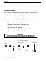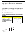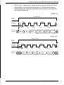
1
Manual – Starlogger FTS & Signal Conditioning Modules
– Models 6103, 6507, 6104, 6105, 6106, 6107, 6108, 6109,
6110, 6114, 6117, 6140, 6141 & 6142
Manual
Starlogger Field Termination Strip
and
Signal Conditioning Modules
Models
6103, 6507, 6104, 6105, 6106, 6107, 6108, 6109, 6110, 6114, 6117, 6140,
6141 & 6142
Revision History
File name / Revision
Date
Authors
Previous version BX
2004
RS/ JH
Unidata Manual - 6103 6507 6104 6105 6106 6107 6108 6109 6110 6114 6117
6140 6141 6142 Starlogger FTS & Sig Cond Issue 2.0 (decrypted)
2007
AB/CB/JH/MS/KC
Copyright © Unidata Pty Ltd 2000-2008. All rights reserved. No part of this publication may be reproduced, transmitted,
transcribed, stored in a retrieval system, or translated into any spoken or computer language, in any form or by any means.
Electronic, mechanical, magnetic, optical, chemical, manual or otherwise, without prior written permission of Unidata Pty Ltd 40
Ladner St, O’Connor Western Australia 6163.
Unidata Manual - 6103 6507 6104 6105 6106 6107 6108 6109 6110 6114 6117 6140 6141 6142 Starlogger FTS & Sig Cond Issue
2.0 (decrypted)
STARLOGGER Field Termination Strip
Table of Contents
1.
INTRODUCTION . . . . . . . . . . . . . . . . . . . . . . . . . . . . . . 1
1.1
2.
3.
4.
How to Use This Supplement . . . . . . . . . . . . . . . . . . . . . . . . 2
INSTALLATION OF FRAME & STRIP . . . . . . . . . . . . . 3
2.1
Model 6103C - Mounting Frame . . . . . . . . . . . . . . . . . . . . . . 3
2.2
Installation of Mounting Frame . . . . . . . . . . . . . . . . . . . . . . 4
2.3
Installation of Field Termination Strip . . . . . . . . . . . . . . . . . 4
TERMINATIONS . . . . . . . . . . . . . . . . . . . . . . . . . . . . . . 5
3.1
Special Purpose Modules . . . . . . . . . . . . . . . . . . . . . . . . . . . 7
3.2
Links . . . . . . . . . . . . . . . . . . . . . . . . . . . . . . . . . . . . . . . . . . . . 8
SIGNAL DESCRIPTION . . . . . . . . . . . . . . . . . . . . . . . 11
4.1
Log Start Sense (Link LS) . . . . . . . . . . . . . . . . . . . . . . . . . . 11
4.2
Analog Inputs . . . . . . . . . . . . . . . . . . . . . . . . . . . . . . . . . . . . 11
4.3
Counters . . . . . . . . . . . . . . . . . . . . . . . . . . . . . . . . . . . . . . . . 13
4.4
4.4.1
4.4.2
4.4.3
4.4.4
4.4.5
External Power . . . . . . . . . . . . . . . . . . . . . . . . . . . . . . . . . . . 14
Back-up Power or Power Supply for Data Logger . . . . . . . . 15
Recharge an Internal NiCad Battery Pack . . . . . . . . . . . . . . 15
Power to all Amplifier Modules . . . . . . . . . . . . . . . . . . . . . . . 15
Power to the Special Purpose Modules . . . . . . . . . . . . . . . . 15
Power to Pwr Terminals. . . . . . . . . . . . . . . . . . . . . . . . . . . . . 16
4.5
4.5.1
4.5.2
4.5.3
Instrument Power Sources . . . . . . . . . . . . . . . . . . . . . . . . . 16
User Power Source . . . . . . . . . . . . . . . . . . . . . . . . . . . . . . . . 17
+6V unregulated, continuous Micropower . . . . . . . . . . . . . . . 17
FTS External Power circuit . . . . . . . . . . . . . . . . . . . . . . . . . . 17
4.6
Analog and Digital Ground . . . . . . . . . . . . . . . . . . . . . . . . . 18
4.7
High Speed Serial Input/Output Ports . . . . . . . . . . . . . . . . 18
4.8
SDI-12 Serial Digital Interface (optional) . . . . . . . . . . . . . . 20
4.9
Outputs . . . . . . . . . . . . . . . . . . . . . . . . . . . . . . . . . . . . . . . . . 20
Contents - i
UNIDATA
4.10
5.
Available Terminals (48, 49, 50) . . . . . . . . . . . . . . . . . . . . 20
SIGNAL CONDITIONING OPTIONS. . . . . . . . . . . . . 21
5.1
5.1.1
5.1.2
5.1.3
Voltage Dividers and Current Loop References . . . . . . .
Model 6104A/B/C/D – Voltage Divider. . . . . . . . . . . . . . . . .
Model 6104I/IE and J – Current Loops . . . . . . . . . . . . . . . .
Model 6507 - Thermistor Temperature Probes . . . . . . . . . .
21
22
23
25
5.2
5.2.1
5.2.2
5.2.3
5.2.4
5.2.5
5.2.6
5.2.7
5.2.8
Amplifier Modules and Accessories . . . . . . . . . . . . . . . .
Model 6105A-DC Amplifier: Single Ended Input . . . . . . . . .
Model 6106A - DC Amplifier: Differential Input . . . . . . . . . .
Model 6107A - Isolated Input Amplifier . . . . . . . . . . . . . . . .
Model 6110A - Low Level Thermocouple Input Amp. . . . . .
Model 6114A - Single Channel Relay Control Module . . . .
Model 6117A – Soil Moisture Transducer Interface . . . . . .
Model 6141A – Isolated Input Module . . . . . . . . . . . . . . . . .
Model 6142A – Universal Amplifier Module. . . . . . . . . . . . .
26
27
28
29
30
31
32
33
34
5.3
Special Purpose Modules . . . . . . . . . . . . . . . . . . . . . . . . . 38
5.3.1 Model 6140A – Site ID Module . . . . . . . . . . . . . . . . . . . . . . 38
5.3.2 Example of Setting the Site ID Number . . . . . . . . . . . . . . . . 39
6.
5.4
Sample Circuit . . . . . . . . . . . . . . . . . . . . . . . . . . . . . . . . . . 40
5.5
Input Filtering for Counter Inputs. . . . . . . . . . . . . . . . . . . 41
INPUT SIGNAL RECORD SHEET . . . . . . . . . . . . . . 42
APPENDIX A – Previous Model 6103B
PDL Field Termination Strip . . . . . . . . . . . . . . . . . A–1
A.
Connections . . . . . . . . . . . . . . . . . . . . . . . . . . . . . . . . . . . A–1
B.
Log Start Sense . . . . . . . . . . . . . . . . . . . . . . . . . . . . . . . . A–4
C.
Site Identification (I.D.) . . . . . . . . . . . . . . . . . . . . . . . . . . A–4
D.
Using Site I.D. . . . . . . . . . . . . . . . . . . . . . . . . . . . . . . . . . . A–4
E.
Disabling Site I.D.. . . . . . . . . . . . . . . . . . . . . . . . . . . . . . . A–5
F.
Site ID Test Program . . . . . . . . . . . . . . . . . . . . . . . . . . . . A–5
G.
Link Descriptions . . . . . . . . . . . . . . . . . . . . . . . . . . . . . . . A–6
ii - Contents
STARLOGGER Field Termination & Signal Conditioning
1. INTRODUCTION
This supplement explains how to use the STARLOGGER Field Termination
Strip (Model 6103D). A Field Termination Strip extends a Data Logger’s input
signal connections to rows of numbered screw terminals, simplifying on-site
installation of a Data Logging System (particularly for complex applications).
This Field Termination Strip can be used with:
–
–
Model 6004 STARLOGGERs
Model 6003 Portable Data Loggers
This supplement also includes a detailed description of how to install the Model
6103C Mounting Frame, and instructions for using signal conditioning modules
which can be attached to the Field Termination Strip. These modules are:
–
–
–
–
–
–
–
–
–
–
Model 6507
Model 6105A
Model 6106A
Model 6107A
Model 6110A
Model 6114A
Model 6117A
Model 6140A
Model 6142A
Model 7121A
Thermistor Temperature Probes
DC Amplifier: Single-Ended Input
DC Amplifier: Differential Input
Isolated Input Amplifier
Low Level Thermocouple Input Amplifier
Single Channel Relay Control Module
Soil Moisture Interface
Site ID Module <<NEW>>
Universal Amplifier Module <<NEW>>
Isolated Input Module
Introducing the STARLOGGER Field Termination Strip
The STARLOGGER Field Termination Strip (Model 6103D) was developed to
take advantage of the technical advancements offered by the Model 6004
STARLOGGER. New features are:
• More links for signal conditioning and custom configuration
• More terminals for scan syncronised power, continuous Micro
power and continuous external power
• Built-in facility to add special purpose modules
• An extra three terminals for custom use
• An Analog Ground is provided for all channels
INTRODUCTION - 1
UNIDATA
To accommodate these features, the newly designed board has links on both
sides. This version of the Field Termination Strip is compatible with the Model
6103B Strip with two exceptions:
a)
Site ID is now a separate module, not a built-in facility
b)
Counter Terminals are different as described below:
Terminal
Model 6103D
Model 6103B
Terminal 5
Counter 2 (pin 12)
c0u (pin 24)
Terminal 7
Counter 1 (pin 24)
c1/c1l (pin 12)
Other Field Termination Strips
Two other STARLOG Field Termination Strips are available.
Model 7100-1 Macro Field Termination Strip
see supplement 6234
Model 6103B PDL Termination Strip
see Appendix A
1.1. How to Use This Supplement
This supplement is divided into five chapters and includes one Appendix:
Introduction - which you are reading now, introduces the Field
Termination Strip & Frame and describes how
information is organised in this supplement.
Installation of Frame and Strip - explains how to install the
Mounting Frame and Field Termination Strip.
Terminations - provides a table describing each termination and
two diagrams that show where terminations and links
are located.
Signal Description - provides specifications for each signal.
Signal Conditioning - describes the signal conditioning options and
amplifier modules listed on the previous page.
2 - INTRODUCTION
STARLOGGER Field Termination & Signal Conditioning
2. INSTALLATION OF FRAME & STRIP
2.1. Model 6103C - Mounting Frame
This frame is designed to be mounted inside a Model 6701 Weatherproof
Mounting Hole
Shelf
Nylon PCB
Mounting
Model 6103-1 Field Termination Strip
& Mounting Frame
Enclosure. (The frame may, however, be screwed to any suitable surface).
The frame provides:
a)
a shelf on which the Data Logger is held in place
b)
holes for nylon PCB mountings for the Termination Strip
c)
4 x 6 mm mounting holes (at each corner)
INSTALLATION OF FRAME & STRIP - 3
UNIDATA
2.2. Installation of Mounting Frame
The Model 6103B and Model 6103D Termination Strips are designed to be
mounted on the Model 6103C Mounting Frame (however the Termination Strip
may be mounted in any convenient location adjacent to the Data Logger).
1. Open the Weatherproof Enclosure and locate Mounting Frame inside with the shelf towards the bottom and the angle support to
the left side of the enclosure.
2. Use four (4) self tapping screws to secure frame to weatherproof
enclosure.
2.3. Installation of Field Termination Strip
The Termination Strip is designed to be mounted on four (4) PCB nylon
mountings. The two at the front of the strip are hinged, and the two at the rear
of the strip have a retention clip. This mounting arrangement allows the strip to
be swung out (forward) from the mounting frame to enable access to the side
(for calibration adjustments) and rear (for configuration & soldering) of the
installed strip.
1. Firmly push the two rear nylon mounts into the holes provided in
the mounting frame. Ensure the retention lever is to the rear.
2. Firmly push the two front mounts into their holes with the hinge
edge to the front.
3. Firmly push the two front mounts into the corresponding mounting holes in the front edge of the Termination Strip (so that the
Data Logger connection is to the top). Ensure that the small
locking tab has passed through the strip and is holding the strip
PCB securely.
4. Swing the strip back onto the rear mounts until the retention clip
engages. (To release strip, push back the top then bottom retention clip lever and swing the strip forwards).
4 - INSTALLATION OF FRAME & STRIP
STARLOGGER Field Termination & Signal Conditioning
3. TERMINATIONS
This section provides brief descriptions of terminations and links and two
diagrams of the Model 6103D Field Termination Strip.
The table below lists each termination. It includes a brief description, the
corresponding channel used in STARLOG Software Version 3, and the corresponding pin in the STARLOGGER Input Signals connector.
Terminal
1
2
3
4
5
6
7
8
9
10
11
12
13
14
Description
Power input for recharging battery and/or
operating logger
PDL: as above and battery output
Digital Ground
16 bit counter input (3kHz)
PDL: 4 bit counter input (300 Hz)
Data Logger power and logic ground
16 bit counter input (20kHz)
PDL: 4/8-bit counter input (1kHz w/prescale)
Data Logger power and logic ground
16 bit counter input (3kHz)
PDL: 4-bit counter input (300Hz)
Data Logger power and logic ground
16 bit counter input (20kHz)
PDL: 4/8-bit counter input w/prescale (1kHz)
Data Logger power and logic ground
High Speed Synchronous Serial Port Data 0
(TTL level Input/Output)
PDL: as above, but Input only
High Speed Synchronous Serial Port Clock 0
Buffered output signal
High Speed Synchronous Serial Port Clock 1
(TTL level Output)
PDL: Clock 1 unbuffered output signal only
Data Logger power and logic ground
Channel
Pin
Battery
16
23
C3
c1u*
25
23
C2
c1/c1l*
12
23
C1
c0u*
24
23
C0
c0l / c0*
11
23
s0 to s7
21
9
22
23
Table continued on next page...
TERMINATIONS - 5
UNIDATA
Terminal
15
16
17
18
19
20
21
22
23
24
25
26
27
28
29
30
31
32
33
34
35
36
37
38
39
40
41
Description
Channel
+5V, 250mA Scan Synchronised User
Power Source
13
ANALOG 7
+ve signal Input
A7
ANALOG 7 –ve signal Input or Power
Ground
ANALOG 6
ANALOG 6
Ground
ANALOG 5
ANALOG 5
Ground
ANALOG 4
ANALOG 4
Ground
ANALOG 3
ANALOG 3
Ground
ANALOG 2
ANALOG 2
Ground
+ve
A6
–ve or Power
+ve
A5
–ve or Power
+ve
A4
–ve or Power
+ve
A3
–ve or Power
+ve
A2
–ve or Power
44
45
46
ANALOG 1
+ve
A1
ANALOG 1
–ve or Power
Ground
A0
ANALOG 0
+ve
ANALOG 0
–ve or PowerA0
Ground
Control, Open Collector output, 30V max.,
Out 0
100mA drive, 5µs – 250ms pulse width
+6V continuous power for external
Micropwr
instruments (1mA maximum)
PDL: not available
Sense 1
Sense 1/SDI-12 (CMOS) input
s8 – s14
SERIAL channels 8 to 14, input & output
Analog Ground
47
CMOS output, HSIO Sync/5µs–250ms pulse
42
43
Table continued on next page...
6 - TERMINATIONS
Pin
Out 1
8
23, 14
7
23, 14
6
23, 14
5
23, 14
4
23, 14
3
23, 14
2
23, 14
1
23, 14
17
18
20
10
14
15
STARLOGGER Field Termination & Signal Conditioning
Terminal
48
49
50
Description
Channel
Pin
Available
3.1. Special Purpose Modules
Hole
1
2
3
4
5
6
7
8
9
10
11
12
13
14
15
16
Description
Clock 0
Data 0
Sense 1/SDI-12
Data 0 (Terminal 11) via link x
Micropower
Out 0
External power (Terminal 1) via link b(ext)
Out 1/HSIO Sync
5Vp (scan synchronised 5V pulse from logger)
Digital Ground
Analog Ground
Counter 0 (C0) (Terminal 9)
Counter 0 (C0) via Link b(C0)
multipurpose (Terminal 48) via link f (see External Power)
Terminal 49 via link u
Terminal 50 via link v
3.2. Links
Link
LS
Description
Sense 0 (Log Start, pin 19) connected to Ground
a
Pull up to +5Vp
b
Divider Series Resistor
c
Pull down to Digital Ground
d
Pull down to Analog Ground
TERMINATIONS - 7
UNIDATA
e
Ax–/Pwr to +5Vp
f
Ax ground to Digital Ground
g
Ax ground to Analog Ground
k
Ax+ terminal to Ax input of Logger
m
Ax–/Pwr to -ve input of amplifier module
n
Ax–/Pwr to Micro power
p
Ax–/Pwr to External Power Circuit
r
Ext. Power Term. to amp. modules & Ax–/Pwr Terms. via Link p
s
S.P.M. hole 14 to amp. modules & Ax–/Pwr terminals via Link p
t
Terminal 48 to S.P.M. hole 14 or Link s
u
Terminal 49 to S.P.M. hole 15 or Link s
v
Terminal 50 to S.P.M. hole 16 or Link s
w
Data 0 Terminal to Data 0 pin of Logger
x
Data 0 Terminal to S.P.M. hole 4
8 - TERMINATIONS
STARLOGGER Field Termination & Signal Conditioning
A = Analog
C = Counter
Channels
C3
Digital Gnd
1
2
3
4
C2
Digital Gnd
5
6
C1
Digital Gnd
7
8
C0
Digital Gnd
9
10
11
12
13
14
15
16
17
18
19
20
21
22
23
SERIAL
Ext. power
Digital Gnd
Data 0
Clock 0
Clock 1
Dig. Gnd
+5 V pulsed
+5 V pulsed
+5 V pulsed
A7
A7 - / Pwr
Ground
A6
A6 - / Pwr
Ground
A5
A5 - / Pwr
Ground
A4
A4 - / Pwr
Ground
A3
A3 - / Pwr
Ground
A2
A2 - / Pwr
Ground
A1
A1 - / Pwr
Ground
A0
A0 - / Pwr
Ground
24
25
26
27
28
29
30
31
32
33
34
35
36
37
38
39
40
41
Cable to
Data Logger
b
c
b
c
b
c
b
c
b
c
42
43
44
Data 1 45
A Gnd 46
Out 1 47
48
49
50
Out 0
Micro Pwr
Sense 1/SDI
Special
Purpose
Modules
mounting holes
ca
b
a
d
c
k
b
a
d
c
k
b
a
d
c
k
b
a
d
c
k
b
a
d
c
k
b
a
d
c
k
b
a
d
c
k
b
a
d
c
k
1
2
3
4
5
6
7
8
9
10
11
12
13
14
15
16
Amplifier module mounting holes
Model 6103D Field Termination Strip (front side)
TERMINATIONS - 9
UNIDATA
b(ext)
r
b(C3)
b(C2)
LS
b(C1)
w
b(C0)
x
s t
u
v
n7
p7
m
n6
p6
m
n5
p5
m
n4
p4
m
n3
p3
m
n2
p2
m
n1
p1
m
n0
p0
m
g7
f7
A7-/Pwr
Ground
g6
f6
A6-/Pwr
Ground
g5
f5
A5-/Pwr
Ground
e4
g4
f4
A4-/Pwr
Ground
e3
g3
f3
A3-/Pwr
Ground
g2
f2
A2-/Pwr
Ground
g1
f1
A1-/Pwr
Ground
g0
f0
A0-/Pwr
Ground
e7
e6
e5
e2
e1
e0
Model 6103D Field Termination Strip (links on back)
10 - TERMINATIONS
STARLOGGER Field Termination & Signal Conditioning
4. SIGNAL DESCRIPTION
The STARLOGGER accepts many different kinds of signal. The Field Termination Strip offers terminals for each input and output. In addition, using links on
the Field Termination board, most terminals can be customised offering an even
wider range of possible inputs and outputs. This section describes each signal
possible using the Field Termination Strip, its links and terminals.
If you are using this Strip with a Portable Data Logger, some features described
below are not available to you – refer to the Appendix.
4.1. Log Start Sense (Link LS)
Normally, the Data Logger only begins to record when an instrument is connected to the INPUT SIGNALS. To sense this condition, there is a Link (LS) on
the back of the Field Termination Strip which connects Pin 19 (Log Start Sense
0) to ground. It is normally connected so that when the FTS is plugged into the
Logger, Sense 0 is connected to ground. This causes the Logger to begin
LS
pin 19 of Logger
operating.
4.2. Analog Inputs
Terminals labelled A0 – A7 can be logged as low resolution values (8 bit data)
or high resolution values (10 bit data). Their usage depends on how you refer to
the input using STARLOG software. The software interprets analog inputs as
low resolution channels when you refer to them as a0 – a7 and high resolution
channels when you refer to them as A0 – A7 (or, h0 – h7 in Version 2 Software).
The Ax-/Pwr Terminal can be used as a negative input (via Link m) if a module
is installed on the FTS which requires this. See diagram section 4.5.
All Analog channels are programmable to carry a signal in one of two ranges: 0
to 2.550 V (2.5 mV per bit) and 0 to 255 mV (250 µV per bit). Input impedance
(when the logger is active) is greater than 1 MΩ. Load impedance (when the
Logger is inactive) for signals less than 500 mV is greater than 1 MΩ, while for
SIGNAL DESCRIPTION - 11
UNIDATA
5Vp
a
Ax
Terminal
b
k
Analog channel
of Logger
18, 21, 24,
27, 30, 33,
36, 39
c
d
Digital
Ground
Analog
Ground
s
5Vp
a
Ax
Terminal
b
k
Analog channel
of Logger
18, 21, 24,
27, 30, 33,
36, 39
e
d
Digital
Ground
Analog
Ground
Micro
Pwr
5Vp
Ax-/pwr
Terminal
c
Ext. Pwr
circuit
p
n
m
19, 22, 25,
28, 31, 34,
37, 40
-ve input
mounting hole for
Amplifier Module
Ground
Terminal
20, 23, 26,
29, 32, 35,
38, 41
g
Analog
Ground
i
g
f
Digital
Ground
s greater than 500 mV, it is 10 kΩ. The recommended source drive impedance
is <10 kΩ.
Analog signals can be conditioned using the following links on the FTS.
Pull-up to +5V
Link a
Used to install thermistor reference resistors or to convert an
analog channel for ON/OFF sensing.
Divider Series Resistor
Link b
Used as part of a voltage divider network (for example, with
Model 6104A/B/C/D Voltage Resistors.) Can also be used for a
series resistor. Or a filter resistor on counter channels.
12 - SIGNAL DESCRIPTION
n
a
l
STARLOGGER Field Termination & Signal Conditioning
Pulldown to Digital Ground
Link c
Used to install a filter capacitor (for pulse inputs) or voltage divider resistor (for voltage attentuation).
Pulldown to Analog Ground
Link d
Protection Series Resistor
Link k or Link b
Used to install a resistor in series with the input signal (to prevent excessive external power being applied to the logger.)
Used for externally powered signals (e.g., voltages, active
pulses).
Direct Input
Link k
Installed to connect the Data Logger channels to their associated terminals when an Amplifier Module is not being used to
pre-condition the input signal. The ’k’ link is removed when an
Amplifier Module is fitted.
Isolated Input
Link m
Installed to connect the Analog -ve signal input to the associated Amplifier Module. The link is installed for Differential or Isolated input signals being connected to differential or isolated
amplifier modules. The link is otherwise not installed.
WARNING: Ensure that Links e, n and p are not installed. Do not use
Link m if these links are installed. Damage may occur to the amplifier
module or an instrument connected to an Ax–/Pwr terminal.
standby = 4.5V
4.3. Counters
100k
Counters are CMOS inputs, suitable for
20 kHz potential free contacts, open
collector outputs or 0–5V to 0–12V DC
digital signals.
10k
Counter
0.001µF (C0/C2) input
Maximum pulse rate to C0 & C2 is 20
kHz, and to C1 & C3 is 3 kHz. Pulse
Cx
Terminal
b(Cx)
Logger
Counter channel
3,5,7,9
c
SIGNAL DESCRIPTION - 13
UNIDATA
rates must also be related to scan rate, to ensure counters do not overflow
before being scanned by the Logger.
Links b and c can be used if attenuation or extra filtering is required.
4.4. External Power
There are several ways to use External Power via the Field Termination Strip.
The external power may be used with an Alkaline or NiCad battery pack as a
backup power source or simply on its own. (A mains power pack and a solar
recharge module are available from UNIDATA.)
The External Power circuit has been designed so that more than one external
power source can be used at the same time. Power can be made available to
the Logger, several Terminals (labelled Ax/Pwr), the amplifier modules, and
special purpose modules. Uses of an External Power Source are:
• Back-up Power or Power Supply for a Logger
• Recharge a Logger’s internal NiCad battery pack
• Provide power to all ext pwr* amplifier mounting holes
• Provide power to Pwr Terminals
• Provide power to/from Special Purpose Modules (7 & 14)
• Provide power to Available Terminal 48
IMPORTANT
The supply voltage to the Data Logger must be maintained at all
times to ensure correct logger operation and data integrity.
7 of Special Purpose Modules
14 of
Special Purpose
Modules
pin 16 of Logger
Ext. power
Terminal
b(ext)
r
s
1
c
t
Pwr Terminals
via link p
all ext. pwr*
mounting holes for
Amplifier Module
14 - SIGNAL DESCRIPTION
48
Available
Terminal
STARLOGGER Field Termination & Signal Conditioning
Voltage to the logger must be in the range of 9V to 20V and able to supply a
load of 100mA peak (increasing to 500mA when recharging a battery).
The diagram below shows the External Power circuit. See section 4.5 to learn
how External Power can be used via Pwr Terminals.
The following sections describe these different uses of External Power.
To install an External Power Supply:
1. Connect +ve to Ext. Power Terminal 1 or Available Terminal 48.
2. Connect -ve to Terminal 2 (or any other Digital Ground).
3. Check that Links are installed or removed depending on how the
installation is using the power (see sections below.)
4.4.1. Back-up Power or Power Supply for Data Logger
Power is supplied from Ext. Power Terminal 1 to STARLOGGER pin 16 when
Link b(ext) is installed. Link c can be used with a zener diode to regulate the
voltage.
4.4.2. Recharge an Internal NiCad Battery Pack
The Data Logger with a NiCad battery pack can be recharged from a solar
recharge panel or a mains power pack or other DC power source. The input
voltage should be between 11V and 20V.
»
NOTE: NiCad Battery Packs require several charge/discharge cycles before their full charge is retained. Therefore, ensure the Data Logger has
been fully charged (connected to solar recharge or mains power pack)
then left to discharge at a fast rate.
Connect recharge power source as described above, in section 4.4.1.
4.4.3. Power to all Amplifier Modules
Power is supplied from Ext. Power Terminal 1 to the ext. pwr* hole of all
amplifier modules when Link b(ext) and Link r are installed. Link c can be used
to regulate the power source. Alternatively, power is supplied from Terminal 48
when Link t and Link s are installed.
Special Purpose Modules can also be used to provide power to the ext. pwr*
hole of all amplifier modules from 14 (via Link s).
SIGNAL DESCRIPTION - 15
UNIDATA
4.4.4. Power to the Special Purpose Modules
External Power can be supplied to hole 7 of the Special Purpose Modules.
Power is supplied from Ext. Power Terminal 1 to hole 7 when Link b(ext) is
installed.
4.4.5. Power to Pwr Terminals
Power is supplied to the Pwr Terminals from Ext. Power Terminal 1 when Links
b(ext), r and p are installed. Alternatively, power is supplied from Available
Terminal 48 to the Pwr Terminals when Links t and s and p are installed or from
Special Purpose Module hole 14 via Links s and p.
4.5. Instrument Power Sources
There are several options for providing power via the Field Termination Strip to
instruments in a data logging system. The following connections can be used to
provide power:
Instrument Power Sources
Connections
Pwr Terminals
(UPS, Micropower or Ext. Power)
19, 22, 25, 28, 31, 34, 37, 40
User Power Source (UPS)
+5V regulated, scan synchronised
15, 16, 17
Micropower
+6V unregulated, continuous
43
Each type of power source is available from an Ax-/Pwr Terminal using links.
Micro
Pwr
5Vp
Ax-/pwr
Terminal
e
19, 22, 25,
28, 31, 34,
37, 40
16 - SIGNAL DESCRIPTION
n
Ext. Pwr
circuit
p
m
-ve input
mounting hole for
Amplifier Module
STARLOGGER Field Termination & Signal Conditioning
WARNING:
Only one link (e, n, p or m) can be safely installed for each channel,
otherwise damage may result. UNIDATA recommends that you
remove any unused links.
4.5.1. User Power Source
The User Power Source (+5V regulated, scan synchronised) is intended to
power instruments associated with the Data Logger. The full load output capability is 250mA in pulsed mode.
The UPS switches on and off (synchronised with the logger scan). Any loads
connected to these outputs will contribute to the drain on the Data Logger
battery (and reduce battery life).
The UPS may be programmed to switch on prior to the logger scan by setting
the Prescan in the STARLOGGER Configuration Table. (See the
STARLOGGER supplement 6244 and the User’s Manual.)
The User Power Source is immediately available through Terminals 15, 16 and
17 and via hole 9 of the Special Purpose Modules. It is also available through
the Ax-/Pwr Terminals via Link e.
4.5.2. +6V unregulated, continuous Micropower
The Micropower source provides +6V unregulated, continuous power for external instruments. The full load output capability is 1mA.
Micropower is immediately available through Terminal 43 and via hole 5 of the
Special Purpose Modules. It is also available through the Ax-/Pwr Terminals via
Link n.
4.5.3. FTS External Power circuit
External power is available to instruments through the Ax-/Pwr Terminals via
Link p and via hole 14 of the Special Purpose Modules (using Link b(ext) as
shown in section 4.4).
SIGNAL DESCRIPTION - 17
UNIDATA
4.6. Analog and Digital Ground
Terminals labelled Ground can be
used as Analog or Digital Grounds
depending on which links are installed (see diagram).
Digital Grounds are also available
through six Terminals labelled
Digital Gnd, the square Amplifier
Module mounting holes (hole 1)
and hole 10 of the Special Purpose Modules.
Ground
Terminal
20, 23, 26,
29, 32, 35,
38, 41
g
Analog
Ground
f
Digital
Ground
Analog Ground is also available through Terminal (46), the second Amplifier
Module mounting holes (hole 2) and hole 11 of the Special Purpose Modules.
4.7. High Speed Serial Input/Output Ports
There are two serial ports:
Port 0
Port 1
Terminal 11 (Data 0)
Terminal 12 (Clock 0)
Terminal 45 (Data 1)
Terminal 13 (Clock 1)
Terminal 15, 16 or 17
The Data 0 Terminal can
also be linked (via Link x) to
hole 4 of the Special Purpose Modules.
Data 0
Terminal
s0 - s7
s8 - s14
+5V sync signal
w
11
pin 21 of Logger
x
4 of Special Purpose
Modules
Each logger scan, the High Speed Serial Ports are read. Any of the +5V power
supplies (Terminals 15, 16, 17) may be used as a “Sync signal” to indicate to
remote equipment that a logger read scan is about to begin. This signal is
usually used to load the serial shift register(s) in the remote equipment in
preparation of being read.
»
NOTE: the first data bit LSB must be present on the Data (0/1) input
within 7ms after the Sync signal.
Serial transfer rate is 50 microseconds per bit with a 30 microsecond gap
between each byte (timing diagrams on next page).
18 - SIGNAL DESCRIPTION
STARLOGGER Field Termination & Signal Conditioning
»
NOTE: every 1 millisecond a logger interrupt sequence adds a 50 microsecond delay to the serial transfer sequence. Transfer starts with the
least significant bit of the least significant byte and each clock reads the
next most significant bit.
SERIAL IN
LOGGER SCAN
Pin 13
SYNC
20us
Pin 9/22
CLOCK 0/1
50 us
10ms
30us
30us
Read Bit 0
Pin 21/10
DATA 0/1
Bit 1
Bit 1
Bit 0
Bit 2
Bit 2
Bit 7
Bit 7
0 (BYTE 1)
Bit 0
SERIAL OUT
LOGGER SCAN
Pin 13
SYNC
30us
Pin 9/22
CLOCK 0/1
50 us
10ms
20us
Write Bit 0
Pin 21/10
DATA 0/1
30us
Bit 1
Bit 0
Bit 2
Bit 1
Bit 7
Bit 2
0 (BYTE 1)
Bit 7
Bit 0
SIGNAL DESCRIPTION - 19
UNIDATA
4.8. SDI-12 Serial Digital Interface (optional)
The STARLOGGERs support the U.S. SDI-12 standard for serial data interchange between the logger and intelligent instruments.
SDI-12 is implemented as an
alternate use of Sense 1 (Terminal 44). Up to ten SDI-12
compatible instruments may
be connected onto this bus.
Programming the SDI-12 interface is supported in Version
3 STARLOG Software.
5Vp
Sense 1/SDI-12
Terminal
a
44
pin 20 of Logger
c
See the STARLOGGER supplement 6244 for details on how to use the SDI-12
Interface.
4.9. Outputs
There are two outputs:
–
–
Out 0
Out 1
Open Collector Output
CMOS Output
Terminal 42
Terminal 47
The Open Collector Output (Out 0) is rated at 100mA and can be used to switch
on/off relays controlling experiments.
4.10. Available Terminals (48, 49, 50)
Three terminals are
available for use via
the Special Purpose
Modules.
To External Power
(see page 14)
Available
Terminals
t
48
14 of Special Purpose
Modules
u
49
15 of Special Purpose
Modules
v
50
20 - SIGNAL DESCRIPTION
16 of Special Purpose
Modules
STARLOGGER Field Termination & Signal Conditioning
5. SIGNAL CONDITIONING OPTIONS
The Field Termination Strip offers convenient facilities to mount signal conditioning and amplifier modules. The mounting holes designations are shown below.
1
2
3
4
5
digital analog -ve external +ve
ground ground input pwr * input
6
8
output
+5V
pulsed
(See page 9 for their locations on the printed circuit board.)
In addition to the links described in the previous section, the following input
signal conditioning modules are available for all Analog channels.
5.1. Voltage Dividers and Current Loop References
When you use one of these options in a STARLOG Data Logging Scheme you
will want to ensure that the voltage divider (or current loop reference) is wired in
properly on the FTS and that you have added it to the Scheme using STARLOG
Software.
To add the option to a Scheme (using Version 3 Software):
1. Open the Scheme Editor.
2. Select the Instruments menu, then Add an Instrument.
3. From the List of Instruments, select the signal conditioning option
you have chosen.
4. Finally, you will want to calculate the Scaling Formula and enter
it in the Transducer menu.
The following sections explain how to wire voltage dividers and current loop
references to the Field Termination Strip.
SIGNAL CONDITIONING OPTIONS - 21
UNIDATA
5.1.1. Model 6104A/B/C/D – Voltage Divider
1. Remove solder blob connection from Link b(see page 9).
2. Insert 100kΩ resistor in Link b.
3. Insert a second resistor in Link c.
4. Do not remove Link k.
V in
R1
V out (0 - 2.55 Volts)
R2
Com
Common
The formula for calculating voltage divider resistors is:
(V in)/(V out) = (R1+R2)/R2
»
Note – Resistor R1 should be larger than 47k (100k suggested).
22 - SIGNAL CONDITIONING OPTIONS
STARLOGGER Field Termination & Signal Conditioning
5.1.2. Model 6104I/IE and J – Current Loops
1. Fit one of the following loop reference resistors to Link c.
Model 6104I
100 Ω for 4–20mA
Model 6104I/E
Model 6104J
120 Ω for 4–20mA
250 Ω for 0–10mA
2. Leave Links b and k connected.
3. Use Analog +ve and Common as signal inputs.
Using Model 6104I
Logger will read 000 at 0mA, 40 at 4mA,
200 at 20mA and 255 at 25.5mA.
Using Model 6104I /E
Logger will read 000 at 0mA, 48 at 4mA,
and 240 at 20mA
Using Model 6104J
Logger will read 100 at 4mA, 250 at 10mA.
Up to eight current loops can be measured by the STARLOGGER. To use more
than one current loop device, we recommend that you use an Isolated Input
Module (Model 7121A) fitted with a Model 6104I, J or I/E to isolate the device
from the logger and to avoid errors caused by ground loops. If you do not use
this module please ensure that it is permissible to common all current loop
grounds at the Data Logger end.
I
Transducer
R 100 Ohms
4 - 20 mA output
Output voltage
to Data Logger
Model 6104I Current Loop Reference
To record information from a current loop device you need to determine the
equivalent zero and full scale values of the transducer.
1. Determine the input signal range corresponding to the 4 – 20 mA
output range. This will be found in the specifications of the device.
eg, level
4 – 20 mA corresponds to 0 – 100 metres
the 0 is the transducer min input
the 100 is the transducer max input
the difference between the two is the transducer input range
SIGNAL CONDITIONING OPTIONS - 23
UNIDATA
FULL SCALE
Trans Max I/P
e.g. 100 m
Trans Min I/P
e.g. 0 m
Zero
mA
0
4
20
25.5
2. Calculate corresponding logger readings. I.e., multiply the reference resistor value by the current loop reading.
e.g.
4 (mA) x 100 (Ω) = 400mV
20 (mA) x 100 (Ω) = 2000mV
Your transducer range is 400 to 2000. Scaling formula is 0 to 100.
These values would now be used to scale the transducer (in the Transducer
window using the STARLOG Software Version 3).
24 - SIGNAL CONDITIONING OPTIONS
STARLOGGER Field Termination & Signal Conditioning
5.1.3. Model 6507 - Thermistor Temperature Probes
1. Fit Link k (factory fitted)
2. Fit thermistor reference (usually, 15kΩ resistor) to Link a.
3. Connect thermistor cable to Analog +ve and Digital Ground
(polarity doesn’t matter).
SIGNAL CONDITIONING OPTIONS - 25
UNIDATA
5.2. Amplifier Modules and Accessories
Small signals may be measured by the Data Logger by using a signal amplifier.
These low power instrumentation amplifiers consist of a small circuit board
module which mounts perpendicular to the Field Termination Strip (FTS)
adjacent to the eight Analog input terminations.
To install the amplifier modules:
1. Remove the appropriate Link k.
2. Position module adjacent to the Analog channel to be conditioned with component side to the top of the FTS.
3. Feed the module leads through the corresponding holes in the
Termination Strip.
4. Secure the module with an M2.5 x 6mm screw & nut to the FTS
(if module is fitted with bracket).
5. Solder the module pins to the strip (from the back) and trim off
excess leads.
Zero & gain adjustments
1. Set gain to maximum.
2. Then set zero. zero is normally set with the minimum (lowest) signal to be measured. (Data Logger should read 0 or 1.)
3. Then set full scale. Full scale is set with the maximum (highest)
signal to be measured (Logger should read 254 or 255.)
»
Note: Calibration is done using Scheme Test Mode of STARLOG Software to read the Data Logger’s memory locations.
26 - SIGNAL CONDITIONING OPTIONS
STARLOGGER Field Termination & Signal Conditioning
5.2.1. Model 6105A-DC Amplifier: Single Ended Input
1. Remove Link k.
2. Install module (see next page).
3. Connect Data Logger and set zero & gain adjustments for desired signal range. The following procedure should be used:
1) Use Scheme Test Mode to look at the channel’s memory
location.
2) Feed an input of 100mV to 1.0 V into i/p.
3) Check the reading on the computer.
4) Adjust zero and gain to read:
0V at 0V input and 2.55V at full-scale.
4. Use Analog +ve and Digital Ground as signal inputs.
Y
Y
+5V
o/p
i/p
nc
8
6
5
3
mounting
bracket
zero
D. Gnd
1
gain
DC Amplifier: Single Ended Input (Model 6105A)
SIGNAL CONDITIONING OPTIONS - 27
UNIDATA
5.2.2. Model 6106A - DC Amplifier: Differential Input
1. Remove Link k.
2. Install Link m.
WARNING: Ensure that Links e, n and p are not installed.
Damage may result if they are.
3. Install module (see below).
4. Connect Data Logger and set zero & gain adjustments for desired signal range.
5. Use Analog +ve and Analog -ve as signal inputs.
Y
+5V
8
Y
o/p
+in
-in
gnd
6
5
3
1
mounting
bracket
gain
zero
DC Amplifier: Differential Input (Model 6106A)
28 - SIGNAL CONDITIONING OPTIONS
STARLOGGER Field Termination & Signal Conditioning
5.2.3. Model 6107A - Isolated Input Amplifier
1. Remove Link k.
2. Install Link m.
WARNING: Ensure that Links e, n and p are not installed.
Damage may result if they are.
3. Install module (see below).
4. Use Analog +ve and Analog -ve as signal inputs.
5. Connect Data Logger and set zero & gain adjustments for desired signal range.
6. Zero will adjust to a reading of 0, 1 or 2 bits.
7. Gain will adjust from unity (*1) to (*100). Zero adjust will become
more sensitive as gain is increased. Recommended input voltage is around 100 millivolts full-scale.
8. For bipolar inputs (+ and - voltage/current) set the zero adjustment to read half scale (127). Input values will then be either
side of this.
9. Power consumption of logging system will increase by approx.
10% for each isolation module fitted.
Y
Y
+5V
o/p
+in
-in
gnd
8
6
5
3
1
mounting
bracket
gain
zero
Isolated Input Amplifier (Model 6107A)
SIGNAL CONDITIONING OPTIONS - 29
UNIDATA
5.2.4. Model 6110A - Low Level Thermocouple Input
Amplifier
If Field Termination Strip Terminals are being used, rather than the module’s
T3/T4, install Link m.
WARNING: Ensure that Links e, n and p are not installed.
Damage may result if they are.
1. Remove Link k.
2. Install module (see below).
3. Connect the thermocouple,
Chromel to Analog +ve,
Alumel to Analog -ve.
T3
4. If optimum cold junction compensation is required use
terminals provided on module (T3=Chromel,
T4=Alumel).
5. Module has no adjustments.
IC
T4
+5V
8
o/p
+in
-in
gnd
6
5
3
1
Low Level Thermocouple Input Amplifier
(Model 6110A)
6. Scaling of signal to logger is
0 to 255°C.
»
Note - this unit is only designed for type “K” thermocouples.
30 - SIGNAL CONDITIONING OPTIONS
STARLOGGER Field Termination & Signal Conditioning
5.2.5. Model 6114A - Single Channel Relay Control Module
To use this Module you will want to define a Scheme which uses an event to
send a Pulse Output to Output 1. (See the STARLOG Users Manual.)
1. Remove Link k.
2. Install Link m.
WARNING: Ensure that Links e, n and p are not installed.
Damage may result if they are.
3. Mount
module.
4. Connect
the top
(upper)
lead
(OUT 0)
to Terminal 42
(open collector output.).
OUT
relay
C3
+5V
N/C
C1
C2
8
6
5
3
D.Gnd
1
to Term 42 (OUT 0)
(C3)
mounting
bracket
Single Channel Relay Control Module (Model 6114A)
The C1/C2 relay
contacts are now connected to the Ax+ and Ax-/pwr terminals. To monitor the
status of the C1/C2 relay contacts, you should use the channel to monitor C3.
The analog channel will now read close to zero when C1 and C2 are shorted
and will read full scale when C1 and C2 are open.
C3
C1
C2
gnd
The relay will be "toggled" with each pulse sent to it by the Logger. This is done
by a PULSE #x instruction.
It is possible to have signal conditioning (voltage divider) and the Analog +ve
and Analog -ve screw terminals free (for the channel which would be occupied
by the 6114A Module) by connecting the 5V and GND wire but not connecting
the C1 and C2 relay wires. These can be replaced with wire, or better, with
terminals. Link k should not be removed and Link m not installed in this case.
SIGNAL CONDITIONING OPTIONS - 31
UNIDATA
5.2.6. Model 6117A – Soil Moisture Transducer Interface
1. Remove Link k.
2. Install Link m. This connects the negative signal input to the interface module.
WARNING: Ensure that Links e, n and p are not installed.
Damage may result if they are.
3. A 10k Ω reference resistor is fitted to the interface between the
5V Logger supply and the output signal. This is the default reference and may be replaced with either 5, 15 or 20kΩ resistors.
4. Solder the interface module to the FTS on the required channel
and tighten the support nut/bolt.
5. Screw the Soil Moisture Block leads into the positive and negative input terminals (of the chosen channel).
N.B. Not positive and ground terminals.
+5V
o/p
+in
-in
gnd
8
6
5
3
1
Model 6117A – Soil Moisture Transducer Interface
32 - SIGNAL CONDITIONING OPTIONS
STARLOGGER Field Termination & Signal Conditioning
5.2.7. Model 6141A – Isolated Input Module
The Isolated Input Module provides isolation for transducers which cannot be
directly connected to the Logger, e.g., current loop transducers powered from
separate supplies. Eight modules can be fitted onto the Field Termination Strip.
1. Remove Link k .
2. Install Link m .
3. Check that Links n, p and e are not installed.
4. Solder Module to FTS on desired analog channel – it will only fit
one way (see diagram.)
5. Connect input signal to A and A-/Pwr terminals on the FTS.
+5V
#s for
Mounting
Holes
8
OUT +IN
6
5
Sig
–IN Gnd
3
2
Pwr
Gnd
1
Model 6141A – Isolated Input Module
Specifications:
Input Signal:
Output Signal:
Isolation:
Power:
single-ended or differential, 0 to ±2.55V DC
isolated input signal, not amplified
flying capacitor, relay isolated
5V DC, 25mA from Logger
SIGNAL CONDITIONING OPTIONS - 33
UNIDATA
5.2.8. Model 6142 – Universal Amplifier Module
This is a multi-range amplifier module for use with Model 6004
STARLOGGERS. It is soldered directly onto the Model 6103D Field Termination
Strip adjacent to a selected analog input channel.
The amplifier extends the STARLOGGER signal range allowing the connection
of:
–
–
–
–
Ø
Thermocouples
Strain Gauges
PT-100 bridges
Thermopiles (pyronometers, radiometers)
Gain Setting
A DIL switch provides six precision gain settings:
SW# ON
all OFF
Input Signal Range
Unipolar
Bipolar
+1.25 V to
2.5 V
–500 mV
Gain
Factor
Logger
Resolution
1
2.5 mV
1
1.0 V
±500 mV
2.5
1.0 V
2
500 mV
±250 mV
5
500 µV
3
250 mV
±125 mV
10
250 µV
4
100 mV
±50 mV
25
100 µV
5
50 mV
±25 mV
50
50 µV
6
10 mV
7
8 ON
8 OFF
250
±5 mV
Adjustable (see below)
ON for single ended signals
OFF for differential signals
10 µV
* Only one selection switch should be ON.
Ø
Adjustable Gain (SW7 ON)
This allows you to customise the amplifier module with your own gain setting.
You need to fit two fixed resistors (R7 and R8) calculated so their total resistance
(sum) is:
Resistance (R7 + R8) =
49.4Kohms
(GAIN−1)
34 - SIGNAL CONDITIONING OPTIONS
STARLOGGER Field Termination & Signal Conditioning
Alternatively, you may substitute a multi-turn trimmer resistor for R8 which then
allows you to adjust the amplifier gain to any setting from 1 to 1,000.
Resistors R7 and R8 are to be soldered into spare locations immediately below
SW7 and SW8. The trimmer resistor if used instead of R8 is soldered into the
spare location next to the DIL switch.
Ø
Fitting the Amplifier to Field Termination Strip
To fit the amplifier to the Field Termination Strip:
1. Solder closed Links b and m. All other links should be open.
(Note: in the factory setting, Links b and k are closed.)
2. Solder module onto the FTS. (It only fits one way.)
Offset Adjust Trimmer
+5V
OUT
8
6
#s for
Mounting
Holes
Ø
Gain Setting Switch
Sig
–IN Gnd
+IN
5
3
2
Pwr
Gnd
1
Model 6142A Universal Amplifier Module
Input Signal Connections
The amplifier accepts single-ended and differential input signals which may be
unipolar or bipolar. Signal inputs are connected into two of three terminals
available for the chosen analog channel:
Input Signal
Description
Analog Terminals
Differential
Unipolar or Bipolar
+ve signal
–ve signal
A
A–/Pwr
Single Ended
Unipolar or Bipolar
+ve signal
–ve signal
A
Ground
Inverting Single Ended
Unipolar or Bipolar
+ve signal
–ve signal
A–/Pwr
Ground
SIGNAL CONDITIONING OPTIONS - 35
UNIDATA
Unipolar Signals – The amplifier is factory set to accept unipolar signals and
no further adjustment is necessary.
Bipolar Signals – The amplifier Offset Adjust Trimmer must be set to read zero
volts output for the most negative input signal to be used. To adjust the Bipolar
offset:
1. Select desired Gain setting (see page 33).
2. Apply the most –ve input signal and adjust Offset Trimmer anticlockwise until you have a reading on that channel (using Test
Mode.)
3. Carefully adjust (clockwise) until reading just changes to zero.
Ø
Software Scaling
To ensure your logged data is reported correctly in reports and graphs, you need
to enter the correct scaling factors for the instrumnet being connected. Use the
Add an Instrument facility in the software package and calculate scaling by the
following method:
from a to b scaling
It is necessary to determine two points (a and b) of measurement.
Point a (lower point)
Set the instrument to measure near the lowest used value and
record that value and the corresponding logger reading in
mV. (Note: a is usually chosen to be 0mV.)
For example,
i) Pressure Sensor
0kPa=
50 kPa =
0mV
1990mV
a
b
ii) pH Probe
7pH =
9.5pH =
500mV
1080mV
a
b
Point b (upper point)
Set the instrument to measure near to its maximum used value
and record that value and the corresponding logger reading
in mV.
Enter these two pairs of readings into the instrument’s scaling
definition:
36 - SIGNAL CONDITIONING OPTIONS
STARLOGGER Field Termination & Signal Conditioning
Using Version 2 Software
transducer range
transducer scaling
0 to 1990mV
0 to 50kPa
Using Version 3 Software
Output:
Scale:
Ø
Analog Voltage mV
Min: 0 Max: 1990
Fullscale a to b
a: 0
b:50
Example
The Model 7201A Net Radiometer outputs a voltage proportional to net solar
radiation in the range of –25 to 175mV. The transducer range is determined as
follows:
Gain factor is 10 (SW3=ON). As the input signal is Bipolar the Amplifier module
must be adjusted for Bipolar signals. This involves introducing an offset of 25mV
(see page 25.)
then output=
(input + 25) x Gain
(input + 25) x 10
mV
mV
For minimum input signal
output = (–25+25) x 10= 0mV
For maximum input signal
output = (175+25) x 10= 2000mV
In the Edit a Transducer menu, set:
Using Version 2
Transducer Range mV
0 to 2000
Using Version 3
Output
Min: 0
Max. 2000
If the calibration factor for the instrument is 0.108mV per W/m2 of solar radiation,
then the scaling factors are calculated as follows:
–25
lower limit =
0.108
= –230
175
= 1612
0.108
upper limit =
In the Edit a Transducer menu, set:
Using Version 2
Transducer Scaling/Formula
–230 to 1612
Using Version 3
Scale: Fullscale
a: –230
b: 1612
SIGNAL CONDITIONING OPTIONS - 37
UNIDATA
5.3. Special Purpose Modules
The Field Termination Strip offers two banks of 16 holes for mounting Special
Purpose Modules. (See diagram page 10 and table pages 7 & 8.)
5.3.1. Model 6140A – Site ID Module
The Site ID Module is a Special Purpose Module that enables you to assign a
number used to identify a logging site. There are two switches and two jumpers
on the module which determine what the Site ID number is. Part of a switch is
used to determine whether or not the Site ID option is being used.
To install the Module:
1. Install Link x.
2. Remove Link w.
3. Set Jumpers on the back of the module for either an 8 bit or 14
bit number.
JP1
JP2
8 bit Mode
removed
installed
14 bit mode
installed
removed
Uses
SW1 only
SW1 & SW2(1–6 only)
4. Install Module in one of the Special Purpose mounting positions
(as shown in diagram).
5. Set the Site ID number use SW1 and SW2 levers 1–6.
6. Enable Site ID by setting SW2 levers 7–off and 8–on.
SW 1
SW 2
MD
ON
1
ON
8
1
MD
8
Jumpers are on the
back of the board.
JP1
JP2
1 2
4
9 10
Model 6140A – Site ID Module
38 - SIGNAL CONDITIONING OPTIONS
16
STARLOGGER Field Termination & Signal Conditioning
Each switch lever in the 8-way DIL switches is labelled with a number from 1 to
8. All but two of these switch levers set the Site ID number. Switch levers 7 and
8 on SW2 are used to enable and disable the Site ID option.
Site ID
Enable
Site ID Number
MD
ON
1 2 3 4
MD
ON
5 6 7 8
LSB
1 2 3 4
5 6 7 8
MSB
Least Significant Byte
Most Significant Byte
The settings to enable and disable Site ID are
shown to the right.
Disabled
MD
The Site ID number is set by the combination
of settings on the first 14 switch levers (see
diagram above, LSB switches 1 to 8 and MSB
switches 1 to 6).
Each switch lever represents a
0 1 2 3
number as shown in the picture 2 2 2 2 ...
ON
on the right. These numbers are
binary values - each switch
lever is a power of 2 in ascend1 2 3 4 5 6
ing order. When a switch lever
is set to the ON position its 1 2 4 8 ...
value is added to the Site ID number.
7
27
MD
7
Enabled
MD
8
28 ...
7
2 13
MD
Enable
Disable
ON
8
1 2 3 4
8
5 6
16,384
For example, switch lever 1 on the first switch (LSB) adds 1 to the Site ID
number, switch lever 3 adds 4 to the Site ID number. (See the example below.)
5.3.2. Example of Setting the Site ID Number
This picture illustrates how to
set the site ID number to 645.
Four switch levers are set to
ON.
20 + 22 +
27 + 29
MD
ON
1 2 3 4
First Switch (LSB)
Switch 1
Switch 3
Switch 8
Second Switch (MSB) Switch 2
The Site ID number is
5 6
7
= 645
MD
Enable
Disable
ON
8
1 2 3 4
5 6
1
(20) =
2
(2 ) =
4
7
(2 ) = 128
(29) = 512
645
SIGNAL CONDITIONING OPTIONS - 39
UNIDATA
5.4. Sample Circuit
This example details a simple monitoring project requiring to measure the
voltage and current in a solar recharge system. The voltage (nominally 12 volts)
is connected to channel Analog 1 which is fitted with a 10:1 voltage divider so
that the logger reading 000 means 0 volts and 255 is 25.5 volts.
The solar power (in or out) is measured by a current shunt which develops 100
millivolts for a current of 10 amps. The shunt input is connected to channel
Analog 0 which is fitted with an isolated amplifier module to provide ground free
reference to the shunt voltage (100mV FSD) and amplification. It may be
desired to adjust the amplifier zero so that zero current flow reads 127 on the
logger. This will allow current flow into and out of the battery to be measured.
Term 39 Analog 0 +ve
+
Solar
Panel
10A to 100 mV Shunt
_
Term 40 Analog 0 -ve
+
Term 36 Analog 1 +ve
Battery
_
Term 38 Common 1
Solar Recharge Monitoring - Example
40 - SIGNAL CONDITIONING OPTIONS
STARLOGGER Field Termination & Signal Conditioning
5.5. Input Filtering for Counter Inputs
All counter inputs have filtering to remove noise and unwanted signals. For
certain types of input (normally relay contacts) the internal filtering may not be
sufficient. A slowly actuating relay contact may have sufficient “contact bounce”
to produce large errors usually in the form of a much larger number of pulses
recorded than were actually applied. This problem can be solved by using an
external filter circuit. The form of external filter used will vary depending upon
the maximum pulse rate to be recorded and the severity of the bounce problem
but would typically take the form of a capacitor across the contacts with a series
resistor as shown in the diagram.
fitted to Link b
Counter Input
R
Contact
C
fitted to Link c
Common
The value of C would typically vary from 0.01 microFarads to 1 microF depending upon the application. The resistor R may not be required for small values of
C and robust contact types but would typically be: 100 Ω to 1k Ω.
SIGNAL CONDITIONING OPTIONS - 41
UNIDATA
6. INPUT SIGNAL RECORD SHEET
Channel
Description
A0
A1
A2
A3
A4
A5
A6
A7
C0
C1
C2
C3
Data 0
Data 1
Out 0
Out 1
Sense 1
42 - INPUT SIGNAL RECORD SHEET
Scaling
from/to
Units
Links/
Modules
Model 6103B Field Termination Strip
APPENDIX A
Previous Model 6103B
PDL Field Termination Strip
The Portable Data Logger Field Termination Strip is the earlier version of the
STARLOGGER Field Termination Strip which is described in detail in the body
of this supplement. In most cases, the operation of the PDL FTS is the same as
the STARLOGGER FTS. However, the board layout is different and some of the
features of the STARLOGGER FTS are different or not available on the PDL
FTS. For instance, Site ID is a switch on the PDL FTS, not a module as
described for the STARLOGGER FTS.
This appendix provides a table and diagram of connections on the PDL FTS. It
also includes signal descriptions (for users of the Portable Data Logger) and
details on how to use the following signal conditioning options (which are not
necessary for the STARLOGGER FTS):
– Model 6108A – AC Voltage Input
– Model 6109A – AC Current Input
– Model 6109B – 5V DC Power Supply
A.1. CONNECTIONS
The table below lists each termination. It includes a brief description, the
corresponding channel used in STARLOG Software Version 3, and the corresponding pin in the Portable Data Logger Input Signals connector.
Terminal
1
2
3
4
5
6
7
8
9
10
Description
Voltage test (must be over 6.5V) or power
input for recharging NiCad Pack
Data Logger signal and logic ground
4-bit counter input (300 Hz) - C1 upper
Data Logger signal and logic ground
4-bit counter input (300 Hz) - C0 upper
Data Logger signal and logic ground
4/8-bit counter input w/prescale (1kHz)
Data Logger signal and logic ground
4/8-bit counter input w/prescale (1kHz)
Data Logger signal and logic ground
Channel
Pin
Battery
16
C1U
C0 U
(C1L) C1
(C0L) C0
23
25
23
24
23
12
23
11
23
Appendix A – A-1
UNIDATA
Terminal
Description
11
SERIAL channels 0 to 7, input only (TTL)
12
CLOCK 0 (TTL Input/Output)
13
CLOCK 1 (TTL Input/Output)
14
Data Logger signal and logic ground
15
+5V, 50mA regulated power for devices
16
+5V, 50mA regulated power for devices
Channel
S0 to S7
22
23
13
13
17
18
19
20
+5V, 50mA regulated power for devices
A7
ANALOG 7
+ve signal Input
A7
ANALOG 7
–ve signal Input
A7
ANALOG 7
Common
21
22
23
24
25
ANALOG 6
ANALOG 6
ANALOG 6
+ve
–ve
Common
ANALOG 5
ANALOG 5
ANALOG 5
ANALOG 4
ANALOG 4
ANALOG 4
ANALOG 3
ANALOG 3
+ve
–ve
Common
+ve
–ve
Common
+ve
–ve
26
27
28
29
30
31
32
33
34
35
36
37
38
39
40
41
42
43
44
45
13
8
23
7
A6
23
6
A5
23
5
A4
23
4
A3
ANALOG 3
Common
ANALOG 2
+ve
A2
ANALOG 2
–ve
ANALOG 2
Common
ANALOG 1
+ve
A1
ANALOG 1
–ve
ANALOG 1
Common
ANALOG 0 - +ve
A0
ANALOG 0 - –ve
ANALOG 0 Common
Control, Open Collector output, 30V,
Output 1
100mA drive, 20ms pulse width
reserved
No Connection
Sense 1, (CMOS) input
S8 - S14
SERIAL channels 8 to 14, input & output
A-2 – Appendix A
Pin
21
9
23
3
23
2
23
1
23
17
18
20
10
Model 6103B Field Termination Strip
Channels
Ext. pwr + 1
GND 2
C1 upper +
GND
C0 upper +
GND
+
_
Ext pwr
b
3
4
5
6
+ 7
C1 lower
GND 8
C0 lower + 9
GND 10
S Data 0 11
E
R Clock 0 12
I Clock 1 13
A
L
GND 14
+5 Volts 15
+5 Volts 16
+5 Volts 17
c
b
c
b
c
d e fg hi j
b
c
b
c
b
c
b
c
b
c
OUT 42
N/C
Sense 1
Data 1 45
1 2 3 4 5 6 78
SITE ID
+5V
a
m
b
c
+ 18
(-) 19
A7
COM 20
a
b
c
a
b
c
+ 21
(-) 22
A6
COM 23
+ 24
(-)
25
A5
COM 26
+ 27
(-)
A4
28
COM 29
+ 30
(-)
A3
31
COM 32
+ 33
(-) 34
A2
COM 35
7
k
m
6
m
k
5
k
a
b
c
m
a
b
c
m
a
b
c
m
4
3
2
a
b
c
+ 36
(-) 37
A1
COM 38
+ 39
(-)
40
A0
COM 41
Cable to
Data Logger
A = Analog
C = Counter
k
Amplifier
module
mounting
holes
k
k
m
1
a
k
m
b
c
0
k
ABBREVIATIONS USED FOR LINKS
a
b
c
d
Pull-up to +5V
Series Resistor
Pull-down to GND
Output 1 Term 42
e
f
g
h
N.C.
Digital 1
Data 1
Data 0
Term 43
Term 44
Term 45
Term 11
i
j
k
m
Term 12
Clock 0
Clock1
Term 13
Direct Input Link
Amplifier Link
Appendix A – A-3
UNIDATA
Terminal
Description
**
Sense 0 (Log Start) connected to GND
Channel
Pin
19
A.2. LOG START SENSE
The ’Log Start’ Sense is a link track on the board which is normally fitted so that
when the FTS is connected to the Logger, pin 19 is connected to ground. This
enables the Logger to recognise when you connect the FTS to the Input Signals
connector and then start the Logger scan.
A.3. SITE IDENTIFICATION (I.D.)
To identify a site from which data was collected users may designate an 8-bit
code for each site using a Field Termination Strip (FTS). This code is set by a
switch located on the FTS and is recorded in the Data Logger memory.
An 8 position DIL switch labelled “SITE I.D” is fitted to the FTS for Site ID.
A.4. USING SITE I.D.
If you are using Version 2 Software and a Field Termination Strip with the Site
ID, you will want to indicate this in the scheme definition. The Site I.D. is
automatically read into Address 254 and generates the required software in the
Logger program.
1. In the Hardware Details section select Fitted in the Site Identification menu
2. In the Output Details section, add the following to the title of a
report or plot for Schemes using Portable Data Loggers:
[val(b254)]
E.g.,
Report Title
Climate Station Number [val(b254)]
The resulting title printed will include the Logger Site ID. Eg, for site #3:
Climate Station Number 3
3. For a Scheme using a MACRO Data Logger, the Site ID requires
two bytes, so, the title of a plot or report must include:
[val(w254)]
A-4 – Appendix A
Model 6103B Field Termination Strip
Note: If you wish to restore Site ID after you have disabled it (by following the
steps below), simply reverse the disable procedure and change the scheme
definition in software. You will lose the first byte of serial data if you do not
restore Site ID hardware.
A.5. DISABLING SITE I.D.
To disable Site ID, ensure that the
scheme definition does not include
Site ID, and:
1. Solder 1 link and cut 1 track
on the back of the FTS.
NOTE: Unless this link is soldered
across, the Site ID will always be read
in ahead of all serial input data,
regardless of whether or not Site ID
is enabled in software.
A.6. SITE I.D. TEST PROGRAM
S
R
Q
P
CUT
The following logger program will store the Site ID in Address 100. Use Test a
Logger in Version 2 software to Put (press Alt-P or select Put from the menu)
the following values in these Addresses. Then look at Address 100.
SOLDER
Address 384
Address 385
Address 386
Address 387
Address 388
Address 8
Address 9
Address 10
72
1
100
0
0
0
128
64
Disabling Site ID
A.7. LINK DESCRIPTIONS
Link ’a’ Pull-up to +5V
... for each Analog channel. This component location is used to install thermistor
reference resistors or to convert an analog channel for ON/OFF sensing.
Appendix A – A-5
UNIDATA
Link ’b’ Series Resistor
... for all channels. This component location is used to install a resistor in series
with the input signal (to prevent excessive external power being applied to the
logger). Used for voltage divider networks and any externally powered signals
(e.g. active pulses, voltages). When a link ’b’ resistor is fitted, the corresponding
’LINK - TRACK’ on the reverse side of the Termination Strip must be cut (1mm
gap) using a sharp knife.
Link ’b’ Divider Series Resistor
Link ’b’ component is also used as part of a resistor voltage divider network
(along with Link ’c’). In this mode, the Link ’k’ is used as a series resistor to
prevent external power being applied to the logger.
Link ’c’ Pulldown to GND
This component location is used to install a filter capacitor (for pulse inputs) or
voltage divider resistor (for voltage attenuation). For all channels.
Links ’d’ to ’j’
Insert links to connect the appropriate Data Logger signals to their associated
terminals.
Link
Logger Pin Terminal
d
17
42
e
18
43
Link ’k’ Direct Input
f
20
44
... for each ANALOG channel. This
g
10
45
wire link is installed to connect the
h
21
11
Data Logger channels to their asi
9
12
sociated terminals when an Amplij
22
13
fier Module is not being used to
pre-condition the input signal. The
’k’ link is removed when an Amplifier Module is fitted.
Link ’m’ Isolated Input
... for each ANALOG channel. This wire link is installed to connect the Analog -ve signal input to the associated Amplifier Module. The link is installed
for Differential or Isolated input signals being connected to differential or isolated amplifier modules. The link is otherwise not installed.
A-6 – Appendix A