1
12/12/2012
UD TEAM
AMSAA
SHAFT TWIST DETECTION TOOL
Authors: David Broadwater, Evan Phillips, Matt Sinnott, Zack Sniffen, Jianhua Su
AMSAA Representatives: Brian Frymiare, Jeffrey Geroso, Hakim Abdurahman
Table of Contents
Executive Summary ...................................................................................................................................... 1
Introduction .................................................................................................................................................. 2
Methods........................................................................................................................................................ 2
Customer Requirements ............................................................................................................................ 2
Ideal Design Features................................................................................................................................. 3
Constraints ................................................................................................................................................. 3
Current Methods of Measurement ........................................................................................................... 3
Metrics ....................................................................................................................................................... 3
Creative Problem Solving ........................................................................................................................... 4
Concept Explanations ................................................................................................................................ 5
Concept Selection ...................................................................................................................................... 6
Design ........................................................................................................................................................... 8
Finalized Design .......................................................................................................................................... 8
Purchasing Components ............................................................................................................................ 8
Fabrication ................................................................................................................................................. 9
Testing/Results ............................................................................................................................................. 9
Proof of Concept ........................................................................................................................................ 9
Isolating the Spline ..................................................................................................................................... 9
Prototype Validation ................................................................................................................................ 10
Path Forward .............................................................................................................................................. 11
Conclusion ....................................................................................................................................... 11
Acknowledgements.......................................................................................................................... 11
Appendix A: Drawing Package .......................................................................................................... 12
Appendix B: MATLAB Code ............................................................................................................... 22
Appendix C: Calculations .................................................................................................................. 25
Appendix D: User’s Manual .............................................................................................................. 26
Appendix E: Assembly Instructions ................................................................................................... 28
Executive Summary
The United States Army Materiel Systems Analysis Activity (AMSAA) has a responsibility
to provide the United States Army with the best equipment possible. Through engineering
analysis, they are able to support the decisions made regarding technology, materiel
acquisition, and the design, development, and sustaining of U.S. Army weapon systems. The
United States Army has recently been experiencing a problem with the differential of a vehicle.
Failure of the differential is common during operation due to torque overload. The failure
stems from plastic twist deformation of a stub spline shaft within the differential.
Since the differential is crucial to the operation of these military vehicles, it is imperative
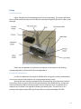
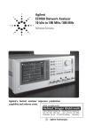
that a tool be developed that can detect these twist deformations. Considering that the plastic
deformation can occur at angles not visible to the naked eye, the tool must be able to identify
these angles as well. An image of a twisted shaft is displayed in Figure 1.
Figure 1: A slightly twisted shaft. The device
must be able to verify that the shaft is twisted.
In order to find a solution to this problem, the University of Delaware’s Team AMSAA
brought about several possible ideas to identify this non-visible twist. One of the restrictions
was that they device should have little contact with the shaft during testing to reduce wear on
both the shaft and the tool. Four main concepts were discussed; a laser displacement system,
an ultrasonic sensor system, a slip on style device that utilized Linear Variable Displacement
Transducers (LVDT’s), and the utilization of photogrammetry. After going through the process
of ranking wants and needs, the method of photogrammetry was determined to be the optimal
solution. This idea seemed appropriate because it is currently used in quality control methods.
The only difference was that the team had to design a system that was much less expensive.
Once the system was designed and a prototype was built, testing began. Many pictures
of the shaft were taken that were run through MATLAB code prepared by the team to
determine the accuracy of the entire system. After extensive testing and many revisions to the
code, the spline could be identified and the angle could be calculated. We have determined
that this device is capable of isolating and measuring the angle of a deformed spline and is a
large improvement over the current method of visual inspection. The use of photogrammetry
allows AMSAA to test shafts of multiple lengths and diameters, making it advantageous to
integrate this design into their quality control check.
1
Introduction
The function of a differential is to ensure that two wheels on the same axle can spin at
different speeds while turning. When a vehicle turns, the inside wheel has a smaller arc than
the outside wheel. In order to keep one of the wheels from slipping, the inside wheel has to
spin slower than the outside wheel. Vehicles that use multiple axles can also have differentials
in between the axles to allow for the rear wheels to spin at different speeds than the front
wheels.
Usually, a differential consists of planetary gears, planet gear carriers, side gears and
other parts. The engine power goes into the differential and drives the planetary carrier
directly. This causes the planetary gear to drive the left and right side wheels. When the vehicle
is running straight, the rotational speed of the left and right wheels and the planet gear carriers
are equal. However, that equilibrium is lost when the vehicle turns; where the inside wheels
have a lower angular velocity than the outside wheels.
The differentials of some of the big military vehicles often times are put under heavy
stress; either over a period of time of continuous use or during a sudden impact of hitting
something in the road, etc. During these types of events, the shaft can be over-torqued causing
plastic twist deformation. The focus of this senior design report is to address a possible solution
to measuring these deformed shafts; some of which are plastically deformed at angles not
visible to the naked eye and to provide AMSAA with a tool to complete this task.
Methods
Customer Requirements
The primary customer for this project is AMSAA. They oversee the design and contribute
money towards the manufacturing of the final product. AMSAA’s primary wants and needs are
for the device to be able to detect non-visible twist while maintaining the safety of their
employees. The secondary customer is the technician, or user who will be operating the device.
The technician must be considered in the design because they desire something that is simple
and easy to use. Another secondary customer that needs to be considered is the United States
Army, whom desire accuracy. If our device is unsuccessful in properly detecting non-visible
twist, the Army’s vehicles will have a greater risk of failure. Figure 2 summarizes the wants and
needs of each customer.
Figure 2: Illustration
summarizing the customers
and their individual wants and
needs
2
Ideal Design Features
AMSAA provided a list of wants that we will be trying to incorporate into the design but
are not necessarily required. They would prefer if the tool could provide a twist measurement
via a gauge, dial, etc. A tool that is adaptable to fit shafts of multiple diameters is also desirable,
as this allows for greater versatility. Lastly, AMSAA would like for the tool to be able to capture
twist with a resolution of 0.01° and an accuracy of ± 0.05°. Although these features are nice to
incorporate, they can be sacrificed for greater functionality.
Constraints
The time it takes to operate this device should be less than five minutes per shaft. This is
a constraint provided by AMSAA and we must ensure that our design is able to meet this
requirement. Two other constraints that we must take into consideration are the size and cost
of the materials required to construct this device. The device would ideally be easy transport
and cost less than $1000, which is the maximum budget proposed by AMSAA. Lastly, OSHA
regulations for use of lasers will have to be followed in the case that lasers are incorporated
into the finalized concept.
Current Methods of Measurement
Currently, inspection is performed by technicians that simply observe the shaft with the
naked eye to determine whether it has been plastically deformed. This leaves a lot of room for
subjectivity because it is difficult to determine twist if the shaft is only twisted by less than 1°.
The main goal of this tool is to eliminate this subjectivity, making the measurements
independent of the operator.
Metrics
Table 1: Displays key metrics that must be taken into consideration when generating concepts
Description
Threshold
Objective
Time to use
5 minutes
1 minute
Resolution
< 1°
0.01°
Accuracy
< 1°
0.05°
Cost
$1000
< $1000
Calibration Frequency
< Quarterly
Never
Number of Steps
5 Steps
1 Step
3
Creative Problem Solving
The design process began with defining the problem and scope and benchmarking
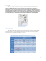
current products on the market. The team looked into different methods of measuring
distances and angles, which can be seen in Figure 3. What was found to be currently on the
market was broken down and applied to the problem. We brainstormed possible solutions and
presented these ideas to the advisor and AMSAA representatives to further discuss and
collaborate to come up with one solution.
C
B
F
D
A
E
Figure 3: Displays benchmarks that were evaluated in order to generate ideas for the concept
generation process. (A) Autocollimator (B) Angle Tool (C) Laser (D) Laser distance measuring
device (E) LVDT (F) Motion Capture
The thought process behind each individual concept can be seen in Figure 4. Each
member started with the notion that the device had to detect twist. From there, two
approaches were made; one of displacement measurement and the other of angle
measurement. Angle measurement continued on to become photogrammetry. Displacement
measurement was further divided into the categories of stationary measurement and rotating
measurement. Rotating measurement went towards a spinning shaft measured by either lasers
or ultrasonic sensors. Stationary measurements split into measuring by lasers/ultrasonic
sensors or LVDT’s.
Figure 4: Breakdown of the creative design process
4
Concept Explanations
Laser Displacement / Ultrasonic Displacement
Several concepts that were considered utilize lasers. The concept shown in Figure 5 uses
two lasers to measure the distance at both ends of the spline. The difference between these
two distances would be calculated to see if plastic deformation had occurred. Another option is
to provide rotation to the shaft and use the two lasers to measure the displacement with
respect to time. If the displacement of one laser changes rapidly while the other remains the
same, the angular velocity and difference in time can be used to determine the degree of twist.
The advantage of using lasers is their high level of accuracy and repeatability. Despite these
advantages, they can be expensive for the level of accuracy and resolution that we have to
achieve. Also, extra precautions have to be taken to protect the eyes from potential damage
that the lasers may cause.
Figure 5: One individual concept utilizing lasers
or ultrasonic sensors
A similar concept was thought up using ultrasonic sensors instead of lasers. This would
allow us to achieve the same resolution and accuracy without the additional expense or
potential safety issues.
Photogrammetry with Insert Strip
A camera system is another concept that was considered that can be seen in Figure 6. A
flexible material with three white dots on it, one on both ends and one in the middle, would be
placed in a spline. A camera would take a picture of the shaft and flexible strip and the picture
would be imported into MATLAB. MATLAB code would be written to isolate the white dots and
measure their positions in both the x and y directions. The difference between these positions
would then be used to calculate the angles between the dots and determine if the spline had
been plastically deformed. This method would be fast in generating a direct angle readout that
AMSAA desires. However, further testing must be performed to ensure the MATLAB program
allows us to meet the required resolution and accuracy.
Figure 6: Initial drawing (a) and Solidworks mock-up (b) for the method of
photogrammetry
5
Over-fit LVDT
The final concept considered was a slip-on device that utilized multiple LVDT’s to
measure the displacement of the spline at different points. Depending on the degree of
deformation, the LVDT's will collect data that can be used to determine plastic deformation. A
conceptual drawing of the device can be seen in Figure 7. Although this system is easy to use, it
will be difficult to manufacture at such a small scale with the given budget. In addition, it may
be too delicate for use in the work environment where the differentials will be evaluated.
Figure 7: Drawing of the over-fit
with LVDT sensor concept
Concept Selection
The table below, Table 2, displays concepts that the team decided to further evaluate
and rank according to metrics and target values. Several concepts were eliminated due to
expected issues in repeatability, durability, or accuracy.
Table 2: Displays the metrics and the ability of the selected concepts to meet the target
values. The values that fail to meet the target values are marked in red.
6
The concept selection table allowed the team to visualize weaknesses in aspects of each
design. After applying the weighted wants and needs to the selection process, Table 3 was
generated. In order to rank the concepts, each was assigned a value from one to five. A score of
five meant that the concept was likely to exceed the desired metric or need.
Table 3: Displays the score for each device based on weighted wants and needs of
the three main customers. Photogrammetry had the highest score followed by
ultrasonic sensors and the over-fit with LVDT while lasers had the lowest score.
Based on the estimations below, ultrasonic sensors would be the cheapest solution to
the problem followed by photogrammetry with an insert strip. These two methods fit the
budget prescribed by AMSAA of $1000. The over fit with LVDT sensors and laser sensors both
exceed this budget. However, the sponsor offered up to $2000 if the team believes the extra
funding could significantly improve the accuracy of the device.
Table 4: Estimated cost table for the four concepts considered
Based on the information presented above in the concept selection and cost tables, the
team selected the method of photogrammetry. This method offers a low cost way to perform
the required task while having a high level of repeatability.
7
Design
Finalized Design
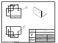
Figure 8 displays the finalized design and all of the components. The camera will take a
picture of the spline and this picture will then be evaluated using MATLAB code in order to find
the angle.
Figure 8: Photo of the prototype of the shaft twist detection tool
Please see the appendix for additional information on the details on the drawing
package (Appendix A) and the MATLAB code (Appendix B).
Purchasing Components
In order to validate our prototype for AMSAA while saving them money, we decided to
use our own cameras and computers for testing and generating results.
Most of the stock aluminum needed for the manufacturing of this device was found in
the machine shop in Spencer while the rest was purchased from McMasterCarr. Screws and
other miscallenous products were purchased at a local hardware store. A complete bill of
materials can be found in the appendix following the drawing files. The total cost of this
prototype was approximatley $80, significantly below our proposed budget of $1000.
8
Fabrication
All items on this device, with the exception of the hold pins used to support the shaft,
were manufactured using aluminum. This is because aluminum has enough strength to support
all of the components and is also very cost effective. All of the items were manufactured using a
mill and drill press. The hold pins were manufactured out of steel using the lathe and inserted
into the shaft holder using a press fit. Steel was used for these pieces because they hold a large
load while having a small diameter. To allow for easy assembly, there are only two types of
screws used in this entire device.
Testing/Results
Proof of Concept
Preliminary testing for this idea started immediately after the concept selection had
been complete. Code that was adopted from a fellow classmate was rewritten in order
calculate angles and distinguish between objects. Pictures were created in Microsoft Paint to
ensure that we knew the angles being measured. A picture of a black background with a single
white line was first used to make sure the code returned 180°. The code returned an angle of
179.9901°. An example of the picture that was used can be seen in Figure 5.
Figure 9: Example of the picture used to test the angle calculating
capabilities of the code. The reason for the pointed end is because the
spline has a tapered end that can be seen in Figure 1.
Isolating the Spline
The second round of tests was done to see what method would best isolate the spline.
Some of our isolation methods include baby powder, reflectivity and light, chalk, crayon, and
markers. These materials were either placed in the valley or on the ridge of one of the splines.
Light was found to be too inconsistent while crayon and chalk did not offer enough coverage to
allow for computer recognition. The baby powder and the marker performed very well when it
came to isolation of the spline. However, there were still disadvantages. The baby powder was
messy and the marker required acetone (nail polish remover) to remove the ink from the
spline. It was determined that removing the ink was easier than cleaning up the baby powder,
encouraging us to isolate the spline using the paint marker.
9
Prototype Validation
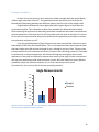
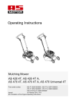
In order to test the accuracy of our device we milled a straight shaft that would ideally
yield an angle extremely close to 0°. The graph below shows the results of 12 trials for the
twisted shaft (alternating between four different splines) and five trials of the straight shaft.
Original data indicated that the straight spline had a higher degree of twist than the
actual twisted spline. This indicated a problem that needed to be addressed and reviewed.
After examining the pictures that were being tested we noticed that there were inconsistencies
with the application of the paint and run off of the paint onto the sides of the spline. To correct
for this we ran more tests while being more careful with the application of the paint to reduce
inconsistencies and paint run off.
From the graph displayed in Figure 10 you can see that the machined spline has a much
lower angle of twist than the twisted splines. This is to be expected. What was unexpected was
that the straight piece did not have an angle of zero, although it was very close. There are two
primary reasons why this could have occurred: (1) Flaws in the machining process (2) Continued
inconsistencies in the paint application. We showed through our testing that more careful
application of the paint can drastically improve the accuracy of the angle. Further cautiousness
with the paint application could yield even better results. We have looked into many different
possibilities (tape, dye, different markers, etc.) to find a way that prevents these
inconsistencies, but currently this is the most promising method.
Angle Measurements
0.4
0.35
Angle (Degrees)
0.3
0.25
0.2
Straight
Twisted
0.15
0.1
0.05
0
Figure 10: Compares the results gathered from measuring a straight shaft for five trials and several twisted shafts for twelve
trials. The error bars display one standard deviation.
10
Path Forward
Team AMSAA created a working prototype for a tool that detects non-visible twist that
is more accurate and dependable than the current method. Further development of spline
isolation will increase the repeatability of this design. In addition, because the testing was all
conducted using computers and cameras owned by the team, a computer and camera would
need to be purchased. The system that was designed can also measure shafts of different
diameters using the same MATLAB code. The only aspect that needs to be modified to
accommodate shafts of different sizes is the stand. Finally, to make the design more portable, a
microcomputer with a dedicated chip for running the code can be attached to the stand itself.
This will also decrease the time it takes to run the test considering the user will not have to
worry about the operating system of a normal laptop.
Conclusion
We were successful in developing a valid prototype that is capable of isolating a spline
and measuring the deformation. Currently, the technicians attempt to measure the
deformation in a spline by simple inspection. Although this method is suitable for obviously
deformed shafts, there are still low quality parts being reused in military vehicles. This creates a
safety hazard for our troops. Our device is an improvement over this outdated method and can
be utilized for other applications because of its versatility.
Acknowledgements
We would like to thank AMSAA for funding this project as well as our sponsors Brian
Frymiare, Jeff Geroso, and Hakim Abdurahman for answering our technical questions
throughout this semester. Also, thanks to our advisor Dr. Samuel Harris for guiding us
throughout this project and Mr. Steve Beard for assisting us with manufacturing.
11
1
2
4
5
3
9
6
8
7
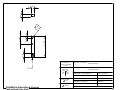
ITEM
NO.
1
2
3
4
5
6
7
8
9
PART NUMBER
Camera Holder
Neck
Square bracket
Holder Pin
Stationary Holder
DESCRIPTION
Spline Holder
Base Plate
Cover Plate
Moving Holder
SolidWorks Educational License
Instructional Use Only
QTY.
1
1
2
2
1
1
1
1
1
TOLERANCES
PROJECT OR CLASS: SENIOR DESIGN
(UNLESS OTHERWISE
NOTED)
DRAWING TITLE: SHAFT TWIST DETECTOR
DECIMAL
.XXX .005
.XX
.010
.X
.050
FRACTIONAL
1/32
ANGULAR
0.5 DEG
DRAWN BY: TEAM AMSAA
DATE: 12/01/2012
CHECKED BY:
DATE:
APPROVED BY:
DATE:
MATERIAL: xxxxxxxxxxxxxx
QUANTITY: 1
SCALE: 1:3
DWG NO: 1
BILLING ACCOUNT:
12
0.75
4.00
1.50
0.50
#
C. 6
S
X2
0.50
0.50
TOLERANCES
PROJECT OR CLASS:
(UNLESS OTHERWISE
NOTED)
1/4"-20
DRAWING TITLE:
DECIMAL
.XXX .005
.XX
.010
.X
.050
FRACTIONAL
1/32
SolidWorks Educational License
Instructional Use Only
ANGULAR
0.5 DEG
SENIOR DESIGN
CAMERA HOLDER
DRAWN BY: TEAM AMSAA
DATE: 12/1/2012
CHECKED BY:
DATE:
APPROVED BY:
DATE:
MATERIAL: ALUMINUM
QUANTITY: 1
SCALE: 1:2
DWG NO: 2
BILLING ACCOUNT:
13
1.50
#6
X2
0.25
0.50
0.50
6.75
#
X 2 10
2.00
1.00
TOLERANCES
DRAWING TITLE:
DECIMAL
.XXX .005
.XX
.010
.X
.050
0.50
1.50
SolidWorks Educational License
Instructional Use Only
PROJECT OR CLASS:
(UNLESS OTHERWISE
NOTED)
FRACTIONAL
1/32
ANGULAR
0.5 DEG
SENIOR DESIGN
NECK
DRAWN BY: TEAM AMSAA
DATE: 12/1/2012
CHECKED BY:
DATE:
APPROVED BY:
DATE:
MATERIAL: Aluminum
QUANTITY: 1
SCALE: 1:1
DWG NO: 3
BILLING ACCOUNT:
14
1.50
0.50
1.50
0.50
# 10
X2
2.00
1.50
0
#1
X2
TOLERANCES
PROJECT OR CLASS:
0.50
(UNLESS OTHERWISE
NOTED)
DRAWING TITLE:
DECIMAL
.XXX .005
.XX
.010
.X
.050
0.50
1.50
FRACTIONAL
1/32
SolidWorks Educational License
Instructional Use Only
ANGULAR
0.5 DEG
SENIOR DESIGN
SQUARE BRACKET
DRAWN BY: Team AMSAA
DATE: 12/1/2012
CHECKED BY:
DATE:
APPROVED BY:
DATE:
MATERIAL: Aluminum
QUANTITY: 2
SCALE: 1:1
DWG NO: 4
BILLING ACCOUNT:
15
.125
.75
TOLERANCES PROJECT OR CLASS: SENIOR DESIGN
(UNLESS OTHERWISE
NOTED)
DECIMAL
.XXX .005
.XX
.010
.X
.050
DRAWING TITLE: HOLDER PIN
DRAWN BY: TEAM AMSAA
DATE: 12/1/2012
CHECKED BY:
DATE:
DATE:
QUANTITY: 2
FRACTIONAL APPROVED BY:
1/32
MATERIAL: STEEL
SolidWorks Educational License
Instructional Use Only
ANGULAR
0.5 DEG
SCALE: 1:1
BILLING ACCOUNT:
DWG NO: 5
16
#10
X2
.375
.375
.375
.75
.375
.25
.75
.375
.124
2.25
2.00
TOLERANCES PROJECT OR CLASS: SENIOR DESIGN
(UNLESS OTHERWISE
NOTED)
.25
2.25
DECIMAL
.XXX .005
.010
.XX
.050
.X
DRAWING TITLE: STATIONARY HOLDER
DRAWN BY: TEAM AMSAA
DATE: 12/1/2012
CHECKED BY:
DATE:
DATE:
QUANTITY: 1
FRACTIONAL APPROVED BY:
1/32
MATERIAL: Aluminum
SolidWorks Educational License
Instructional Use Only
ANGULAR
0.5 DEG
SCALE: 1:1
BILLING ACCOUNT:
DWG NO: 6
17
1.00
#10
X2
1.00
0.25
0.50
0.50
0.25
1.00
1.35
310
0.07
0.25
1.00
2.25
TOLERANCES
PROJECT OR CLASS:
(UNLESS OTHERWISE
NOTED)
DRAWING TITLE:
DECIMAL
.XXX .005
.XX
.010
.X
.050
FRACTIONAL
1/32
SolidWorks Educational License
Instructional Use Only
ANGULAR
0.5 DEG
SENIOR DESIGN
SPLINE HOLDER
DRAWN BY: TEAM AMSAA
DATE: 12/1/2012
CHECKED BY:
DATE:
APPROVED BY:
DATE:
MATERIAL: Aluminum
QUANTITY:
SCALE: 1:1
DWG NO: 7
1
BILLING ACCOUNT:
18
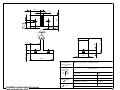
3.375
All Holes are #10
and are CS
.875
.500
1.500
8.000
3.000
2.688
.500 .813
2.500 2.375
1.125 1.000
.500
1.250
1.750
.500
3.000
3.625
TOLERANCES PROJECT OR CLASS: SENIOR DESIGN
(UNLESS OTHERWISE
NOTED)
.188
12.000
DECIMAL
.XXX .005
.XX
.010
.X
.050
DRAWING TITLE: BASE PLATE
DRAWN BY: TEAM AMSAA
DATE: 12/1/2012
CHECKED BY:
DATE:
DATE:
QUANTITY: 1
FRACTIONAL APPROVED BY:
1/32
MATERIAL: ALUMINUM
SolidWorks Educational License
Instructional Use Only
ANGULAR
0.5 DEG
SCALE: 1:4
BILLING ACCOUNT:
DWG NO: 8
19
1.00
1.00
0.75
2.25
0.38
# 10
X2
R0.1
3
0.25
0.25
3.00
0.25
3.00
TOLERANCES
PROJECT OR CLASS:
(UNLESS OTHERWISE
NOTED)
DRAWING TITLE:
DECIMAL
.XXX .005
.XX
.010
.X
.050
FRACTIONAL
1/32
SolidWorks Educational License
Instructional Use Only
ANGULAR
0.5 DEG
SENIOR DESIGN
COVER PLATE
DRAWN BY: TEAM AMSAA
DATE: 12/1/2012
CHECKED BY:
DATE:
APPROVED BY:
DATE:
MATERIAL: Aluminum
QUANTITY: 1
SCALE: 1:1
DWG NO: 9
BILLING ACCOUNT:
20
.75
.75
.25
.375
.124
2.56
2.1875
.13
.50
1.75
TOLERANCES PROJECT OR CLASS: SENIOR DESIGN
(UNLESS OTHERWISE
NOTED)
DECIMAL
.XXX .005
.XX
.010
.X
.050
DRAWING TITLE: MOVING HOLDER
DRAWN BY: TEAM AMSAA
DATE: 12/1/2012
CHECKED BY:
DATE:
DATE:
QUANTITY: 1
FRACTIONAL APPROVED BY:
1/32
MATERIAL: Aluminum
SolidWorks Educational License
Instructional Use Only
ANGULAR
0.5 DEG
SCALE: 1:1
BILLING ACCOUNT:
DWG NO: 10
21
Appendix B: MATLAB Code
Code to find the angle of twist in the spline
function [splineAngle, newArray] = finalTest
close all; clear all;
%User will select a photo to analyze. The code will take the green pixels and
%convent them to white and convert all other pixels to black.
photo = uigetfile('*.JPG','Select the image files to
process','MultiSelect','on');
image = imread(photo);
matSize = size(image);
pixels = matSize(1,1)*matSize(1,2);
image2 = reshape(image,prod(matSize(1:2)),3);
image3 = zeros(pixels,1);
image3(:,1) = abs(image2(:,2) - image2(:,1));
image4(:,1) = image3(:,1) >= 23;
for i = 1:pixels
if image4(i,1) == 1
image2(i,1)=255; image2(i,3)=255; image2(i,2)=255;
else image2(i,2)=0; image2(i,1)=0; image2(i,3)=0;
end
end
image5 = reshape(image2,matSize);
BWimage = im2bw(image5);
%Inverting the image
%If using the program for the first time, consider using imshow to
%display the processed image and ensure that the objects of interest
%are white on a black background.
%BWimage =~ BWimage;
%B is the output of the coordinates of the green lines surrounding
%each object. The if statement will delete the extra pixels if they
%exceed a certain size.
B = bwboundaries(BWimage);
k=1;
for j = 1:length(B)
if length(B{j}) > 3000
newArray{k}=B{j};
k=k+1;
end
end
N(i)=length(newArray);
if N ~= 1
display('Examine the image for errors. May need to retake the picture.')
end
%Display the last processed image.
% clf
% imshow(BWimage)
% text(10,10,strcat('\color{green}Objects Found:',num2str(N)))
% hold on
%Finds the 2 sets of y coordinates for 33 specified x coordinates (11 on
22
%the right side of the spline, 11 in the middle, and 11 on the left side.
%Takes the average of the 11 coordinates in each region and uses this
%average value and the average X coordinate to calculate the angle. Taking
%the average is meant
matrix = newArray{1};
E = max(matrix);
F = min(matrix);
Xmin = F(1,2);
Xmax = E(1,2);
center = floor((Xmin+Xmax)/2);
%Preallocate
yLoc = zeros(33,2);
xcoordinates(1:11,1) = Xmin+20:10:Xmin+120;
xcoordinates(12:22,1) = center-50:10:center+50;
xcoordinates(23:33,1) = Xmax-120:10:Xmax-20;
xmatrix = matrix(:,2);
ymatrix = matrix(:,1);
for j = 1:33
i = xcoordinates(j);
x = find(xmatrix == i);
yLoc(j,1) = ymatrix(x(1));
yLoc(j,2) = ymatrix(x(2));
end
X(1) = Xmin + 70;
X(2) = center;
X(3) = Xmax - 70;
yAverage(1) = sum((sum(yLoc(1:11,:))))/22;
yAverage(2) = sum((sum(yLoc(12:22,:))))/22;
yAverage(3) = sum((sum(yLoc(23:33,:))))/22;
P12 = sqrt((X(2)- X(1))^2 + (yAverage(2) - yAverage(1))^2);
P13 = sqrt((X(3)- X(1))^2 + (yAverage(3) - yAverage(1))^2);
P23 = sqrt((X(2)- X(3))^2 + (yAverage(2) - yAverage(3))^2);
Angle = acos((P12^2 + P23^2 - P13^2)/(2*P12*P23));
newAngle = Angle * (180/pi);
splineAngle = 180 - newAngle;
fprintf('The spline angle is %2.5f \n',splineAngle);
if splineAngle < 0.63
disp('Keep it!')
else disp ('Throw Away!')
end
end
23
Code to view the last processed image
function [Fimage] = imagerGreen
%close all; clear all;
figure
photo = uigetfile('*.JPG','Select the image files to
process','MultiSelect','on');
image = imread(photo);
matSize = size(image);
pixels = matSize(1,1)*matSize(1,2);
image2 = reshape(image,prod(matSize(1:2)),3);
image3 = zeros(pixels,1);
image3(:,1) = abs(image2(:,2) - image2(:,1));
image4(:,1) = image3(:,1) >= 30;
for i = 1:pixels
if image4(i,1) == 1
image2(i,1)=255; image2(i,3)=255; image2(i,2)=255;
else image2(i,2)=0; image2(i,1)=0; image2(i,3)=0;
end
end
image4 = reshape(image2,matSize);
Fimage = imshow(image4);
24
Appendix C: Calculations
The calculations shown below were used in order to determine when a spline shaft has reached
plastic deformation.
( )
( )
( )
()
(
)
(
)
(
)(
)
25
APPENDIX D: User’s Manual
Twist Detection Tool: Instruction Manual
Step 1: Line up the hole that is on the bottom of the camera with the holder screw. Rotate the camera in
a clockwise direction until the camera will not rotate any further and then make a quarter turn back in
order to make the camera parallel with the ground. The result of this step should look like Figure 1.
Figure 1: Correct position of the camera on the spline holder.
Step 2: Shake marker thoroughly and apply to an external source until it is possible to achieve a steady
line of paint.
Step 3: Apply the paint to an individual spline of the shaft on the side that contains the fuse. Hold the
marker at approximately a 15 degree angle as indicated in Figure 2 (a) in order to control the amount of
paint applied. Continue until there is a solid layer of paint covering the spline as demonstrated in Figure
2 (b).
Figure 2: (a) Proper angle of application for the marker to the spline shaft. (b) Fully covered individual
spline.
26
Step 4: Once the paint is completely applied, the shaft may be placed into the holding device with the
painted spline directly underneath the camera. See Figure 3 for an illustration.
Figure 3: Correct placement of spline shaft into holding device.
Step 5: Turn on the camera.
Step 6: Make sure that the camera’s macro mode setting is enabled and the flash settings are off. If you
are unfamiliar with macro settings or flash settings, refer to Figure 4.
ON
OFF
Figure 4. General macro mode setting and flash setting symbol.
Step 7: Hold the picture button that is on top of the camera until it auto-focuses and takes a picture.
Step 8: Import the picture onto the corresponding computer.
Step 9: Test the picture using the MATLAB program. The MATLAB program will output the angle of the
shaft and instruct the user on how to continue.
27
APPENDIX E: ASSEMBLY INSTRUCTIONS 1. Gather the Camera Holder, Neck, both Square Brackets, the ¼”‐20 stud, 2 #10 screws and bolts, and 2 #6 screws 2. Assemble them as in Figure 1 below with 2 #10 screws, 2 #10 nuts, and 2 #6 screws 3. Screw the ¼”‐20 stud into the hole on the Camera Holder 4. Gather the Stationary Holder, one of the Holder Pins, the Spline Holder 5. Press fit the Holder Pin into the top hole of the Stationary Holder as can be seen in Figure 2. The Spline Holder is a part of this sub‐assembly but will not be attached to anything at this time. 6. Gather the Moving Holder, Cover Plate, and the second Holder Pin 7. Press fit the Holder Pin into the top hole of the Moving Holder as can be seen in Figure 3. 8. Place the Cover Plate over the Stationary Holder so that the holes are closest to the Holder Pin (see Figure 3) 9. Gather 10 #10 screws and bolts 10. Place all sub assemblies on the Base Plate according to Figure 4. 11. From below, insert all screws so that they protrude from the top of the device and screw on the bolts 12. The final assembly should resemble Figure 5 Figure2
Figure1 Figure3 Figure5 Figure4 28