1
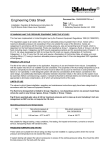
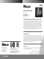
Installation and Operating Instructions
*
Swing Check Valve
Fig. 3047 ( / ” - 2”)
Fig. 3047 W* ( / ” - 2”)
1
2
3
4
CE MARKING AND THE PRESSURE EQUIPMENT DIRECTIVE 97/23/EC
This has been implemented in United Kingdom law by the Pressure Equipment Regulations 1999 (SI 1999/2001).
The regulations apply to all valves with a maximum allowable pressure greater than 0.5 bar. Valves with a maximum
allowable pressure not exceeding 0.5 bar are outside the scope of the Directive. Valves are categorised in
accordance with the maximum working pressure, size and ascending level of hazard, which is dependent on the
fluid being transported. Fluids are classified as Group 1, dangerous fluids or Group 2, all other fluids including
steam. Categories are SEP (sound engineering practice) and for ascending levels of hazard, I, II, III or IV. All valves
designated as SEP do not bear the CE mark nor require a Declaration of Conformity. Categories I, II, III or IV carry
the CE mark and require a Declaration of Conformity (Note- all valves up to and including 25mm (1”) having a
maximum allowable pressure greater than 0.5 bar are designated SEP regardless of fluid group.)
PRODUCT LIFE CYCLE
The life of the valve is dependent on its application, frequency of use and freedom from misuse. Compatibility with
the system into which it is installed must be considered. The properties of the fluid being transported such as
pressure, temperature and the nature of the fluid must be taken into account to minimise or avoid premature failure
or non-operability. A well-designed system will take into consideration all the factors considered in the valve design,
but additionally electrolytic interaction between dissimilar metals in the valve and the system must be examined.
Before commissioning a system, it should be flushed to eliminate debris and chemically cleaned as appropriate to
eliminate contamination, all of which will prolong the life of the valve.
FAX: +44 (0)1744 26912
EMAIL: [email protected]
EMAIL: [email protected]
www.cranebsu.com
LIMITS OF USE
FM311 ISO 9001
• Designed and manufactured under quality management
systems in accordance with BS EN ISO 9001-2008
Every effort has been made to ensure that the information contained in
this publication is accurate at the time of publishing. Hattersley assumes
no responsibility or liability for typographical errors or omissions or for
any misinterpretation of the information within the publication and
reserves the right to change without notice.
H_SCV_0613
IOM_004B03047D799_v5
PO BOX 719, IPSWICH, IP1 9DU
HOME SALES: +44 (0) 1744 458670
EXPORT SALES: +44 (0)1744 458671
TECHNICAL HELPLINE: 0845 604 1790
The valves to which these installation, operation and maintenance instructions apply have been categorised in
accordance with the Pressure Equipment Directive.
Installation and Operating Instructions
These products are categorised for Group 1 Liquid, but are not necessarily suitable for all fluids in this
group. Refer to Hattersley Technical Application Engineers for advice. Codes of practice, specifications and
regulations should be referred to for specific guidance for valve selection on hazardous service.
These valves may also be used on Group 2 Liquids, but on no account must they be used on any Group 1 or
Group 2 gases.
Fig 3047 and Fig 3047W Bronze check valves PN25 pressure ratings and in sizes up to and including 2 inch
are categorised as SEP and do not require the CE mark
OPERATING PRESSURES AND TEMPERATURES
Fig No.
PN
Non-shock pressure at temperature range
Non-shock pressure at max. temperature
3047
25
–10oC to 95oC
95 oC
3047W
25
o
o
–10 C to 85 C
85 oC
Not suitable for fatigue loading, creep conditions, fire testing, fire hazard environment, corrosive or erosive service,
transporting fluids with abrasive solids, high velocity gases that can cause shock waves.
Valves must be provided with adequate support. Adjoining pipework must be
supported to avoid the imposition of pipeline strains on the valve body.
INSTALLATION
Prior to installation, a check of the identification plate and body marking must be made to ensure that the correct valve is
being installed.
Valves are precision manufactured items and as such, should not be subjected to misuse such as careless handling,
allowing dirt to enter the valve through the end ports and lack of cleaning both valve and system before operation.
All special packaging material must be removed.
Confirm that the pipe threading length is correct to avoid excessive penetration of the pipe into the valve, which would
otherwise cause damage.
Thread sealing compounds appropriate to the application should be used but excessive use should be avoided, since this
increases thread interference and may cause overstressing of the body ends. Immediately prior to valve installation, the
pipework to which the valve is to be fastened should be checked for cleanliness and freedom from debris.
Ensure the threads are properly engaged and proceed to tighten the valve onto the pipe. The wrench must only be located
on the valve end into which the pipe is being threaded to avoid distortion of the valve.
PRESSURE/TEMPERATURE RATING
These valves must be installed in a piping system where the normal pressure and temperature do not exceed the
above ratings.
If system testing will subject the valve to pressures in excess of the working pressure rating please check with
Hattersley helpline.
The maximum allowable pressure in valves as specified in the standards is for non-shock conditions. Water hammer
and impact for example, should be avoided.
If the limits of use specified in these instructions are exceeded or if the valve is used on applications for which it was
not designed, a potential hazard could result.
LAYOUT AND SITING
The Fig. 3047 and Fig. 3047W check valve may be installed in horizontal pipework and vertical pipework if the flow
is in an upwards direction.
Swing Check valves having 6 diameters of straight lengths of pipe upstream and 3 diameters downstream are
suitable for velocities up to 3 metres/second. If the valve is situated such that turbulence occurs, or is situated close
to reciprocating pumps then the velocity should not exceed 2 metres/second.
This valve must not be fitted in vertical pipelines with the flow downwards. In a horizontal pipeline the valve should
be installed with the hexagon cap uppermost. The valve must be installed with the direction arrow on the body
coincident with the direction of the flow in the pipeline.
02
Hattersley Swing Check Valve (SCV)
OPERATION
The Fig. 3047 and Fig. 3047W check valve are self-acting.
MAINTENANCE
The Fig. 3047 and 3047W check valve are almost maintenance free. After a prolonged period in service it may
require the replacement of the resilient disk facing.
The valve should be at zero pressure and ambient temperature prior to any inspection.
1. Unscrew and remove the cap and hinge pin plug.
2. Withdraw the hinge pin and remove the disk/hinge assembly through the top of the body.
3. Unscrew the resilient disk retaining nut and remove the old/damaged disk.
4. Inspect the disk for damage and remove any deposits or debris from the main metal disk and the sealing face in
the body.
5. Fit the new resilient disk and retighten the retaining nut.
6. Lock the nut to the metal disk by deforming the mating threads using a centre punch and hammer.
7. Refit into the valve body, and tighten the cap and hinge pin plug, inspect for leakage.
Hattersley Swing Check Valve (SCV)
03