1
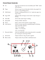
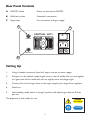
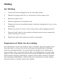
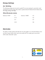
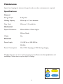
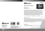
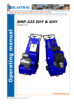
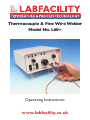
Thermocouple & Fine Wire Welder
Model No. L60+
Operating Instructions
www.labfacility.co.uk
CONTENTS
Page
Operating Instructions . . . . . . . . . . . . . . . . . . . . . . . . . . . . . . . . . . . . . . . . . . . . . . . . . . 2
Accessories . . . . . . . . . . . . . . . . . . . . . . . . . . . . . . . . . . . . . . . . . . . . . . . . . . . . . . . . . . . . 3
Front Panel Controls. . . . . . . . . . . . . . . . . . . . . . . . . . . . . . . . . . . . . . . . . . . . . . . . . . . . 4
Rear Panel Controls . . . . . . . . . . . . . . . . . . . . . . . . . . . . . . . . . . . . . . . . . . . . . . . . . . . . 5
Setting Up Procedure. . . . . . . . . . . . . . . . . . . . . . . . . . . . . . . . . . . . . . . . . . . . . . . . . . . 5
Welding Instructions . . . . . . . . . . . . . . . . . . . . . . . . . . . . . . . . . . . . . . . . . . . . . . . . . . . . 6
Energy Settings. . . . . . . . . . . . . . . . . . . . . . . . . . . . . . . . . . . . . . . . . . . . . . . . . . . . . . . . . 7
Electrodes . . . . . . . . . . . . . . . . . . . . . . . . . . . . . . . . . . . . . . . . . . . . . . . . . . . . . . . . . . . . . 7
Maintenance . . . . . . . . . . . . . . . . . . . . . . . . . . . . . . . . . . . . . . . . . . . . . . . . . . . . . . . . . . . 8
1
THERMOCOUPLE AND FINE WIRE WELDER
MODEL L60+
Operating Instructions
The L60+ welder is designed for sensor manufacturers to produce commercial grade
thermocouple junctions, and by users of large numbers of exposed junction
thermocouples such as test and development laboratories where multipoint temperature
sensing of test pieces is required.
No special skills are required and most people will be capable of producing quality work
with minimal practice. A satisfactory thermocouple junction is produced without using
argon, but where argon is available a momentary purge is automatically triggered
immediately prior to the weld to give optimum weld integrity.
DANGER
Arc welding
Wear suitable
eye protection
Safety Note
1.
Always protect the eyes with a suitable filter during welding – never view the
weld discharge with the naked eye.
2.
Avoid touching the rear of the welder during operation as the power switch heat
sink may run hot.This is a normal operating condition.
3.
Do not allow the hand to directly contact the welding electrode during
operation.
2
Accessories
Standard:
Wire Holding Pliers With Lead
Safety Glasses
Magnifying Eyeglass
Spare Carbon Electrode
Spare 2A Fuse
Argon Hose
Hexagon key (for electrode change)
Mains Lead
Footswitch (Allows One Handed Operation)
Optional:
Spare Carbon Electrodes
Gas Flow Meter & Valve
DANGER
Arc welding
Wear suitable
eye protection
3
Front Panel Controls
A
Arc
Argon gas and weld current controlled by the “Weld” switch.
LED indication.
B
Purge
Allows the gas line and electrode shield to be purged of air
prior to a new welding period.
C
Weld Switch
Initiates a welding operation (in “arc” mode also opens the
Argon valve).
D
Argon LED
Indicates when the Argon control valve is open and gas is
flowing.
E
Wait LED
Glows when weld charge is building.
F.
Ready LED
“Ready to Weld” indication.
G
Power
Rotary control of the capacitor charge voltage.
H
Level selector
Selects the total capacitance available giving the following
values with LED indication.
“LO” = 0 to 6 Joules
“MED” = 0 to 28 Joules
“HI” = 0 to 64 Joules
I
Electrode Holder
Holds the replaceable carbon electrode which is accessible
by removing the outer Argon Shield.
J
Red socket
Output socket for using the pliers supplied.
K
Black socket
Output socket, this provides an additional earth.
E
H
LO
MED
HI
WAIT
I
F
READY
G
LABFACILITY
LEVEL
ARC
POWER
ARC
-
+
WELD ARGON PURGE
C
D
B
A
K
4
J
Rear Panel Controls
A
ON/OFF switch
Power to instrument ON/OFF
B
Weld jack socket
Footswitch connection
C
Argon inlet
For connection to Argon supply
C
A
CAUTION - HOT!
ARGON IN
FOOTSWITCH
B
Setting Up
1.
Using a suitable connector fused at 5 amps, connect to mains supply.
2.
If Argon is to be utilised, couple argon hose to rear of welder. Do not over-tighten
as a good seal will be made with the nut slightly more than finger tight.
3.
Connect free end of argon hose to the argon supply via an argon flow regulator.
4.
Switch on.
5.
Hold welding mode switch in “purge” position and adjust argon flow to 8 litres
per min.
The apparatus is now ready for use.
DANGER
Arc welding
Wear suitable
eye protection
5
Welding
Arc Welding
1.
Connect the work-holding pliers to the red output socket.
2.
Depress the purge switch for 3 or 4 seconds to rid the system of air.
3.
Reset the mode to “Arc”.
4.
Set the energy level to the desired value.
5.
Prepare the wires to be welded and grip in the pliers, leaving about 1mm or more
protruding.
6.
Position the wires 5 or 6mm in front of the carbon, whilst steadying the hand.
7.
Press the “weld” switch or foot switch and slowly move the work towards the
carbon until the arc is struck.
8.
Release the switch and remove the work for examination.
Preparation of Wires for Arc welding
For small diameter wires, strip off about 12mm of insulation and twist together.Then,
with side cutters or scissors cut the wire off square leaving sufficient un-insulated
material to give approximately 1mm protruding when gripped in the welding pliers.
Larger diameter wires may be held side by side in the welding pliers, but ensure that
they are in firm contact with each other and trimmed off square.This method will be
found useful for attaching solid leads to resistance thermometer detectors. However,
when attaching stranded leads, it will be found more convenient to use the twisting
method and then to carefully untwist after welding.
6
Energy Settings
Arc Welding
The following settings may be used as a guide.The correct setting for a particular metal
combination and wire gauge will produce a spherical bead. A flattened bead indicates that
the energy setting is too high.
Wire Diameter (mm)
Switch at “LOW”
0.1
Switch at “HIGH”
0.3
0.15
0.5
0.2
0.7
0.25
0.8
Electrodes
To replace or adjust carbon electrode, first turn the welder on its side and slacken screw
on base of argon shield, which may be then pulled off.This reveals grub screw which
holds carbon electrode in place.
DANGER
Arc welding
Wear suitable
eye protection
7
Maintenance
Apart from keeping the electrode in good order, no other maintenance is required.
Specifications
General
Energy Output
0-60 Joules
Welding Capacity
Wires up to 1.1mm diameter
Duty Cycle
Minimum 5-10 welds/min
Mechanical
Physical Dimensions
220mm Wide x 120mm High x
250mm Depth
Weight
4kg
Electrical
Power Supply
110-120 Vac or 220-250 Vac,
50-60Hz
Power Consumption
Max 170VA dropping to 20VA during charging
All information given is correct at time of going to press. Please note that specifications and
availability of certain items may be subject to change.
DANGER
Arc welding
Wear suitable
eye protection
8
To receive our regular email newsletter, please register your details on our website
www.labfacility.co.uk
SOUTHERN UK & EXPORT DIVISION: Units 5,6 & 7, Block K, Southern Cross Industrial Estate,
Shripney Road, Bognor Regis, West Sussex PO22 9SE
Export Sales: tel: +44(0)1243 871287 fax: +44(0)1243 871281
email: [email protected]
Southern UK Sales: tel: +44(0)1243 871280 fax: +44(0)1243 871281
email: [email protected]
NORTHERN UK DIVISION: Eden Place, Unit 3b Outgang Lane, Dinnington, Sheffield S25 3QT
Northern UK Sales: tel: +44(0)1909 569446 fax: +44(0)1909 550632
email: [email protected]
Certificate No. 4746
050004.OM.C