1
lllllllllllllllllllllllllllllllllllllllllllllllllllllllllllllllllllllllllll
US005151945A
United States Patent [19]
[11]
Patent Number:
Lee et a1.
[45]
Date of Patent:
[54]
DETERMINATION OF AMBIENT LIGHT
LEVEL CHANGES IN VISUAL IMAGES
[75] Inventors: George C. Lee, Williamsville, N,Y.;
Xianyi Sun, Beijing, Taiwan
[73] Assignee:
The Research Foundation of State
Univ. of N.Y., Albany, NY.
[51]
[52]
Sep. 11, 1990
Int. Cl.5 ............................................. .. G06K 9/00
US. Cl. ........................................ .. 382/1; 382/37;
382/4; 358/105
[58]
Field of Search ..................... .. 382/1, 4, 2, 37, 38,
[56]
382/39, 42; 358/105, 108, 109, 101
References Cited
U.S. PATENT DOCUMENTS
4,337,481
6/l982
4,408,224
4,455,550
4,679,077
4,737,847
l0/l983
6/1984
7/1987
4/1988
ing the steps of: obtaining a ?rst digital representation of
a ?rst visual image. where the ?rst digital representation ‘
comprises a ?rst plurality of pixels, and each pixel has a
gray scale indicative of light intensity; obtaining a sec
ond digital representation of a second visual image,
where the second digital representation comprises a
second plurality of pixels, and each pixel has a gray
scale indicative of light intensity; and selectively mak
ing a ?rst predetermined number of comparisons of
corresponding pixels from the ?rst and second digital
[21] Appl. No.: 580,629
[22] Filed:
5,151,945
Sep. 29, 1992
representations to determine whether a difference in
ambient light intensity exists between the ?rst and sec
ond visual images, and, selectively making a second
predetermined number of comparisons of correspond
ing pixels from the ?rst and second digital representa
tions if and only if no difference in ambient light inten
sity exists between the ?rst and second visual images,
and indicating an alarm condition when a percentage of
Mick et al. ........................ .. 358/105
the second predetermined number of comparisons result
in pixels having a difference in gray scale of a predeter
mined amount. Apparatus is also described for the pur
pose of implementing the method.
Primary Examiner—Michael Razavi
ABSTRACT
3 Claims, 7 Drawing Sheets
Micro?che Appendix Included
A visual image comparison method is provided, includ
‘(1 Micro?che, 21 Pages)
{S 7]
11
IO
13
/
j
2
I
I
'
CAMERA ——‘-—>
I
VISUAL
IMAGE
COMPARATOR
|
1
,/12
‘
CONTROLLED
VICE
DE
8
US. Patent
Sep. 29, 1992
Sheet 1 of 7
5,151,945
Izw):
VISUAL
IMAGE
COMPARATOR
k
V
CONTROLLED
DEVICES
MONITOR
FIG. 1 A
ANALOG TO
DIGITAL
CONVERTER
CONTROLLER
EXECUTOR
ISA-A
CONTROLLED
DEVICES
US. Patent
Sep. 29, 1992
5,151,945
Sheet 2 of 7
/
INPUT DIGITAL IMAGE
INTO SECOND MEMORY
(OLD IMAGE) '
INPUT DIGITAL IMAGE
INTO FIRST MEMORY
(NEW IMAGE)
CHANGE IN
ABIENT LIGHT
INTENSITY ;>
SUF FICI ENT DIFFERENCE
SIGNAL ALARM
TRANSFER DIGITAL
IMAGE FROM FIRST
MEMORY TO SECOND
MEMORY
FIG.2
26
,
20
US. Patent
Sep. 29, 1992
Sheet 3 0f 7
5,151,945
COLUMNS
.-
|
\
\
a
V
~
~
\
-
\
-
ROWS
FIG.3A
M240,“
.. . . . .. .. .. ::::'.:.':
X(24O,256)
COLUMNS
.
ROWS
.
.
-
.
1
'
.
-
-
.
.
-
.
-
.
.
-
YW)
-:::
".::::::
YBJ)
::::: ‘
9 . . . ..
US. Patent
Sep. 29, 1992
Sheet 4 of 7
5,151,945
5lO.n.
5V
RESET
OSC
F IG.4A
US. Patent
Sep. 29, 1992
I
\ REI
8
Sheet 7 0f 7
CONTROLLED
SWITCH
CONTROLLED
REZ
I IOV
AC ""
FIG.4E
AC POWER SUPPLY
5,151,945
1
5,151,945
2
in ambient light. Yoshida suggests displacing the cap
DETERMINATION OF AMBIENT LIGHT LEVEL
CHANGES IN VISUAL IMAGES
turing of the two video images in time by an amount
which is negligible with respect to the ambient changes
in brightness. For example. Yoshida suggests that dis
placing the capture of the images by 15 seconds to 1
In accordance with 37 C.F.R. 1.96. a micro?che ap
pendix is to be considered a portion of the entire “writ
ten description” of this invention in conformance with
35 U.S.C. 112. The appendix includes one micro?che
minute is suitable to overcome the effects of gradually
having 21 data frames.
dependent upon the rate of change of the ambient light
changing brightness. Unfortunately, this attempt to
solve the problem is limited in its usefulness in that it is
BACKGROUND OF THE INVENTION
The present invention relates generally to video sur
veillance methods and apparatus and, more particularly,
to automatic surveillance systems which detect changes
in a ?eld of view over time and indicate an alarm condi
tion accordingly.
The use of video cameras at remote locations for
surveillance by video monitors is well known. In some
circumstances, constant human supervision or monitor
ing is required. A typical example of this manual sur 20
veillance method would be the remote placement of
working hours to monitor a robbery attempt. Many
security systems typically employ a plurality of video
monitoring location where a human guard keeps watch.
occur.
SUMMARY OF THE INVENTION
cameras in a retail store to detect shoplifting; another
example would be a camera in a bank activated during
cameras situated throughout a facility, with a central
intensity. While one time setting may be suitable for
slowly changing intensity levels (such as might occur at
sunset, dawn, etc.), this same time setting may be unsuit
able for rapid changes (such as clouds passing overhead
during a thunderstorm, or sudden dimming of lights in
an of?ce, etc.).
What is needed, then, is a surveillance system which
is not only immune to false alarms caused by changes in
ambient light conditions, but also functions indepen
dently of the speed with which these ambient changes
25
A visual image comparison method is provided, in
cluding the steps of obtaining a ?rst digital representa
tion of a ?rst visual image, where the ?rst digital repre
sentation comprises a ?rst matrix having a plurality of
pixels, and each pixel has a gray scale value indicative
of light intensity; obtaining a second digital representa
These manual systems are predecessors within the ?eld
of the present invention.
Human interaction in surveillance is extremely expen 30 tion of a second visual image, where the second digital
representation comprises a second matrix having a plu
sive. In some circumstances, then, it is economical and
rality of pixels, and each pixel has a gray scale value
desirable to replace the human observer with an auto
indicative of light intensity; and selectively making a
matic surveillance system, or at least to alleviate the
?rst predetermined number of comparisons of corre
guard from the burden of constant supervision, freeing
sponding pixels from the ?rst and second digital repre
him to perform other useful work. Automatic surveil
lance systems have evolved, therefore, to handle situa
tions which do not require constant human supervision.
An example of this application would be the monitoring
of an empty room at night, where an automatic system
would sense the entry of an intruder and sound an
alarm. It may be desired to monitor an outdoor parking
lot, or perhaps the entrance or exit of a building. Other
applications include monitoring products or workpieces
on an assembly line, etc. In a multitude of applications,
automatic surveillance methods and systems are more
economical and even more reliable than syst’ems requir
ing constant human interaction.
A common problem encountered by all automatic
surveillance systems, both indoor and outdoor, involves
sentations to determine whether a difference in ambient
light intensity exists between the ?rst and second visual
images, and, selectively making a second predetermined
number of comparisons of corresponding pixels from
the ?rst and second digital representations if and only if
no difference in ambient light intensity exists between
the ?rst and second visual images, and indicating an
alarm condition when a percentage of the second prede
termined number of comparisons result in pixels having
a difference in gray scale of a predetermined amount.
The ?rst and second visual images can be images ob
tained at different locations simultaneously, images
taken of a single location at different times, or images
obtained at different locations at different times. An
false alarms triggered by changes in ambient light inten
apparatus is also provided to implement the method of
sity. For example, in monitoring an outdoor scene such
as a parking lot, a cloud passing overhead may substan
tially affect ambient light conditions and trigger a false
alarm. Even in indoor applications, many of?ces em
the invention.
A primary object of the invention is to provide a
ploy automatic light dimming circuits which dim the
lights in the evening, causing problems for automatic
surveillance systems.
Attempts to solve the false triggering problem are
well documented in the art. One well-known technique
involves the use of automatic exposure lenses or cam
eras to compensate for ambient light intensity varia
tions. Unfortunately, this method is limited to only
small variations in intensity. Another alleged solution is
visual image comparison method which functions inde
pendently of ambient changes in light intensity between
the visual images being compared.
A secondary object is to provide a visual image com
parison method which functions independently of the
time rate of change of ambient light intensity between a
?rst and second visual image being compared.
BRIEF DESCRIPTION OF THE DRAWINGS
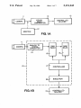
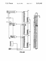
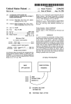
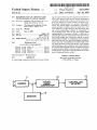
FIG. 1A is a general block diagram of a video surveil
' lance apparatus which utilizes the present invention.
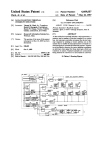
FIG. 1B is a general block diagram similar to FIG.
1983). Yoshida broadly discloses a surveillance method 65 1A but expanded to show the major elements of the
visual image comparator.
which includes the comparison of two digitized video
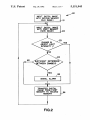
FIG. 2 is a flow diagram illustrating the general
image signals taken of a “place scenery” at different
method of the invention.
points in time. To solve the problem caused by changes
proposed by Yoshida in U.S. Pat. No. 4,408,224 (Oct. 4,
3
5,151,945
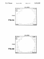
FIG. 3A represents a ?rst digital representation of a
?rst visual image, and FIG. 38 represents a second
digital representation of a second visual image, which
two images are compared by the present invention.
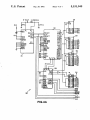
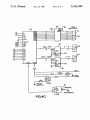
FIGS. 4A-4E illustrate a schematic circuit diagram
of an alternative embodiment of the invention which
utilizes a dedicated “hard" circuit.
DETAILED DESCRIPTION OF THE
INVENTION
The present invention is a visual image comparison
system which enables automatic surveillance of a loca
tion over time, or simultaneous monitoring of two or
more identical or nearly identical objects. The system
described herein may be used in homes, museums,
stores, of?ces, and other commercial establishments as
well as in hotels, airports, and other special places re
quiring security measures. The invention may also ?nd
applications in industry such as, for example, the moni
4
NEW) 15 is transferred to RAMwLD) 16, and the new
digital image is stored in RAMA-Em 15. Controller 17
controls the transferring of the old image from RAM(.
NEW) 15 to RAM(01_D)16 and then compares the old and
new images. If a suf?cient difference exists between the
images, controller 17 sends an alarm signal to executor I
18. Executor l8 activates various auxiliary alarm de
vices as discussed previously.
In the preferred embodiment depicted in FIG. 1B,
10 both the old and new digitally represented images are
stored in separate memories prior to comparison. It
should be readily apparent, however, that it is also pos
sible to compare temporally displaced images by only
storing the earlier image in memory and then compar
ing a present or new image to the old in real time, elimi
nating the need for one of the memories. It is also possi
ble to compare two distinct images simultaneously re
ceived by two video cameras at the same time, eliminat
ing both memories. For example, one camera could be
toring of a workpiece on an assembly line. In addition to
focused on an image (such as a ?ngerprint) while a
security surveillance applications, the system may also
second camera scans other images looking for a match.
be used to compare two visual images (?ngerprints,
etc.) simultaneously to determine if the images are the
An inverter circuit connected to controller 17 or execu
tor 18 would sound an alarm only when a match is
found. Similarly, on an assembly line, one camera could
The system is used in conjunction with a video cam 25 be focused on a static image of a workpiece as it should
appear at a certain step in assembly, while a second
era or other means of providing an analog visual image.
camera is timed to monitor workpieces on the actual
A visual image comparator method and apparatus ana
same or nearly the same.
lyzes the analog visual images and sounds an alarm if a
suf?cient difference exists between two different im
assembly line. If the two images don’t match, a suitable
warning would be given to indicate a possible product
30 defect.
ages.
7
Adverting once again to the preferred embodiment
The apparatus of the invention is outlined in block
form in FIG. 1A to show how the invention interacts
depicted in FIG. IE, it should be noted that VIC 10
may be implemented in apparatus form in one of at least
with auxiliary equipment. Visual image comparator
two ways. In a ?rst embodiment, VIC 10 may comprise
(VIC) 10 represents the present invention, which oper'
ates on visual images provided by video camera 11 or, 35 software run by a conventional computer such as an
alternatively, by optional video monitor 12. When a
IBM PC® or compatible computer. In a second em
change in non-ambient light intensity or when motion
bodiment, VIC 10 may comprise a dedicated circuit
occurs within the ?eld of view of camera 11 (or within
specially designed to implement the method of the in
monitor 12), VIC 10 signals an alarm, represented by
vention. In either case, the method of comparison is the
controlled devices 13in FIG. 1A. Controlled devices 13 40 same, and this method is described herebelow:
may be any device capable of indicating an alarm (bell,
The Visual Image Comparison Method
whistle, buzzer, light, etc.) or it may even comprise a
The present invention broadly comprises a visual
video monitor which automatically displays the chang
ing video image when a change occurs. For example, in .image comparison method, comprising the steps of:
one application contemplated by the inventors, a video 45 obtaining a ?rst digital representation of a ?rst visual
camera is focused on the entrance to a residence. As
someone approaches the entrance, the motion is de
tected by the system. The system may be programmed
image comprising a ?rst plurality of pixels, where each
pixel has a gray scale indicative of light intensity; ob
taining a second digital representation of a second visual
image comprising a second plurality of pixels, where
each pixel has a gray scale indicative of light intensity;
selectively making a ?rst predetermined number of
comparisons of corresponding pixels from the ?rst and
to display the video camera image on a television set (or
to display the image as a “picture-within-a-picture” on 50
the television) to indicate the arrival of a visitor. When
the television set is turned off, the system may be pro
second digital representations to determine whether a
grammed to turn on lights or sound audible alarms, etc.
(or to turn the television on to display the changing
difference in ambient light intensity exists between the
video image). In yet another application, the camera
might be focused on an infant’s crib to monitor the baby
at sleep. If the infant awakens, moves or becomes dis
tressed, the parents can be alerted accordingly.
A preferred embodiment of the invention which
shows VIC 10 in more detail is shown conceptually in
FIG. 1B. VIC 10 includes A/D converter 14, RAM(.
NEW) 15, RAM(0LD) 16, controller 17 and executor 18.
A/D converter 14 converts the analog video signal
provided by camera 14 into digitized signals. The digital
?rst and second visual images, and, selectively making a
second predetermined number of comparisons of corre
sponding pixels from the ?rst and second digital repre
sentations if and only if no difference in ambient light '
intensity exists between the ?rst and second visual im
ages, and indicating an alarm condition when a percent
age of the second predetermined number of compari
sons result in pixels having a difference in gray scale of
a predetermined amount.
FIG. 2 illustrates by flow diagram the general
representation of a ?rst visual image so obtained is then 65 method of the invention. To begin the process, it is
assumed that a frame of digitized data representative of
stored in RAMWEW) 15, which is a random access mem
a second visual image is already stored in a second
ory. At a subsequent instant in time, a new image signal
memory (box 21). A new image is then digitized and a
is obtained. The digital representation stored in RAM(.
5
5,151,945
6
3. The magnitude, K, ofthe gray scale difference neces
sary within a given pixel-pair to signify an alarm
condition.
It can be readily appreciated that a comparison of
new frame of digitized data is stored in a ?rst memory
(box 22). The new and old digital representations of ?rst
and second visual images, respectively. are then com
pared (box 23). A decision is made as to whether a
difference in ambient light intensity exists between the
each pixel of the ?rst image with its corresponding pixel
two images. Such a difference would occur, for exam
of the second image would be extremely time consum
ple, if the sun suddenly disappeared behind a cloud; if a
ing if all 61,440 pixels of each image were compared.
tree branch was moved by the wind in front of the
camera lens; at sunset or sunrise, or if the lights in a
room were turned on or off, etc. In other words, such a
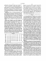
Obviously, comparison processing time is related to the
number of pixels compared. For example, in a software
driven embodiment of the invention, a comparison of
change would likely be distributed somewhat through
20,480 pixels (skipping every third pixel) takes approxi
out the entire visual ?eld. The essence of the invention
mately 0.71 seconds of processing time, whereas com
is to distinguish between such ambient intensity
changes, and other changes, such as might be caused by
approximately 0.43 seconds.
someone or something entering or leaving the visual
?eld. The invention will indicate an alarm condition for
the latter condition, but will not sound a false alarm for
the former condition.
If an ambient intensity difference is found to exist in
box 23, control is passed to box 26, where the digital
image previously stored in the ?rst memory is trans
ferred to the second memory (and the image previously
paring 8,777 pixels (skipping every seventh pixel) takes
15
Fortunately, it is unnecessary to compare each and
every pixel to achieve a system which functions inde
pendently of changes in ambient light intensity. More
over, the number of comparisons needed, the percent
age of those comparisons which must show a difference,
the spatial distribution of the pixels compared, and the
magnitude of the gray difference between pixels being
compared are variables dependent upon whether the
comparison is being done to determine a change in
stored in the second memory is erased). The method
then proceeds back to box 22 where a new image is 25 ambient light intensity, or to determine an alarm condi
tion.
The ?rst comparison of the method determines
whether a difference in ambient light intensity exists
between the ?rst and second visual images. In a pre
where a second comparison is done between the ?rst
and second visual images. If a suf?cient difference exists 30 ferred embodiment, experiments indicate that, for an
image comprising 61,440 pixels, as few as 1,536 pixels
between the two images, an alarm is indicated (box 25).
need be compared (skipping every 40th pixel, i.e.,
Otherwise, control passes to box 26 and the process
J
=40) and yet still achieve accurate and reliable results.
repeats as described above. ,
In other words, it is only necessary to compare approxi
It is the unique method used to compare old and new
images which enables the present invention to operate 35 mately 2% to about 4% of the total image, assuming
that the compared pixels are distributed throughout the
independently of changes in ambient light intensity.
image. Of course, more pixels could be compared, but
This comparison is best understood with reference to
this would increase processing time. The processing
FIGS. 3A and 3B.
time required to compare 1,536 pixels is less than 0.3
FIG. 3A represents a ?rst digital representation of a
?rst visual image. The representation comprises a plu 40 seconds.
Experiments also indicate that, for J =25-40, N may
rality Of pixels X(1,1), X03), X03), . . . , X(Z4Q,256), where
be in the approximate range of N=90-110 to achieve
each pixel has an associated gray scale indicative of
accurate results. In other words, approximately 3% to
brightness or light intensity. For example, an individual
about 8% of the compared pixel-pairs must exceed the
pixel may have a gray scale, G, ranging from 0 to 63,
predetermined K value (magnitude of gray difference)
where 0 indicates black and 63 indicates white, or from
in order to indicate a difference in ambient light inten
0 to 255, where 0 indicates black and 255 indicates white
sity.
depending on the interface board used.
Finally, in making the ambient light comparison,
Similarly, FIG. 3B represents a second digital repre ' experiments indicate that a low K value is preferred
sentation of a second visual image, such as that of an
50 (e.g., K=2 or 3) since the change in ambient light may
image obtained at a later point in time than the ?rst
be very small. This is the magnitude, K, of the gray
image mentioned previously. The second representation
scale difference within a given pixel-pair comparison
comprises a plurality Of pixels Y(],1), Yul), Y(1,3), . . . ,
necessary to signify an alarm condition. For example, if
“240356), where each pixel has an associated gray scale
one pixel has a gray scale of 21 and its corresponding
as discussed above.
55 pixel has a gray scale of 27, then the gray scale differ
The comparison method of the invention functions by
ence is said to be 6 (27-21). The value of K selected
comparing digital representations of corresponding
affects the sensitivity of the system. The lower the value
obtained and stored and the process repeated.
If, on the other hand, no ambient intensity change or
difference is detected, control passes directly to box 24,
pixels of the ?rst and second images. For example,
X(3,1) and Y(3,1) are corresponding pixels. There are
three variables which factor into the comparison pro
cess as follows:
1. The total number of comparisons of corresponding .
of K, the more sensitive the system. In a system such as
the preferred embodiment where each pixel has a gray
scale range from 0 to 63, a K value of 2 to 3 is a differ
ence equivalent to 3%—5% of the total gray scale.
Once again, experimental data suggest that values of
pixels from each image. (Determined by J, the num
ber of pixels to jump over when making comparisons
from each image).
K=2 or 3 ensure reliable operation in nearly all ambient
light conditions. This is not to say that other values of K
65 will not be suitable, only that values of K=2 or 3 are
2. The number of comparisons, N, which must yield a
difference in gray scale in order to signify an alarm
condition.
preferred. In fact, other values of K have been proven
to achieve suitable results, depending upon the ambient
light conditions. Obviously, the method will still work
5,151,945
7
satisfactorily with larger K values, but will simply be
less sensitive to changes in ambient light intensity.
Also, it is noted that, in a preferred embodiment, the
8
Moreover, it is not necessary to actually make all the
planned comparisons if, for example, a sequence of
early comparisons indicate a problem. For instance, if
2,458 comparisons are to be made, but only 90 compari
pixels compared are uniformly distributed throughout
the images (i.e., every 25th pixel, every 40th pixel, etc.).
sons indicating a difference are required to signal an
alarm, then the processing can stop as soon as the 90th
This is not to imply that uniform distribution is abso
lutely necessary, although it is preferred. In checking
comparison indicating a difference is reached. This may
for ambient light differences, it is necessary, however,
occur at any time (i.e., on the 2,450th comparison or
even on the 90th comparison, etc.). This manner of
that compared pixels be distributed widely throughout
the images.
processing ensures reliability by preventing false alarms
while minimizing processing time.
Summarizing, then, in a preferred embodiment, the
?rst comparison to determine if a difference in ambient
light intensity exists between the ?rst and second im
A First Physical Embodiment For Implementing The
ages is preferably made with K=2 or 3, N=90—l 10, and
Method
J=25-40. These ranges are intended to be guidelines 5
In
a
?rst
embodiment,
the method of the invention
and approximations, and it is not intended or implied
may
be
implemented
using
a software driven system of
that other combinations of J, K and N will not work
a personal computer, such as an IBM-PC or equivalent.
satisfactorily, only that satisfactory results have been
The software necessary to implement the system is
included in the micro?che appendix. Also required in a
obtained when the variables are selected within these
ranges.
.
In the second comparison, or so-called common sur
veillance mode, a different range of the variables are
utilized to determine if an alarm condition exists. It has
video imaging interface for converting the analog video
signal to digital signals for processing by the computer.
often results in false alarms, and high values of N result
course, any commercially available equivalent video
imaging interface could be used in lieu of the DT2803.
In a preferred software driven embodiment, a Model
DT2803 “Frame Grabber” was used as the video inter
been determined experimentally that N=2 or 3
achieves satisfactory results when J =3-7. While other 25 face (available from Data Translation, Inc., 100 Locke
values of N may also work, it has been found that N=l
Drive, Marlborough, Massachusetts 01752-1192). Of
in low surveillance sensitivities which may not detect
small moving objects within the visual ?eld. Similarly,
The DT2803 Frame Grabber is a single-board, micro- although larger values of J may work satisfactorily, as J 30 processor-based video imaging interface, suitable for
increases small moving objects may not be detected.
use with the IBM personal computer series (IBM
In a preferred embodiment, the K value in the second
PC/AT/XT) and functionally IBM-compatible per
comparison is determined by the average gray scale
sonal computers. This video interface provides real»
value of the ambient (AGA) according to Table I be-_
time 6-bit digitization of an RS-l70/RS-330/NTSC or
low. The average gray scale value of the ambient is 35
determined by adding all of the individual gray scales
values (GS) of each considered pixel and then dividing
this total by the number of pixels considered.
TABLE I
AGA
K
AGA
K
AGA
K
AGA
1
I
ll
l6
21
18
31
2
2
l2
l6
22
l8
32
3
4
l3
l6
23
l8
33
4
7
l4
l6
24
l8
34
5
9
l5
l6
25
l8
35
6
l2
l6
l6
26
l9
36
CCIR/PAL compatible input signal. The DT2803
plugs into the PC backplane, and includes a video imag
ing input analog to digital converter and look-up tables,
a 64 kilobyte frame-store memory, a video imaging
output digital to analog converter and look-up tables,
7
l4
l7
l7
27
l9
37
8
l6
18
l7
28
l9
38
9
l6
19_
17
29
l9
39
10
l6
20
17
30
l9
40
K
20
20
2O '
2O
21
21
21
22
22
22
AGA
K
41
23
42
23
43
23
44
24
45
24
46
24-
47
24
48
25
49
25
AGA
K
AGA
K
51
26
61
30
52
26
62
31
53
26
63
32
54
27'
55
27
56
27
57
28
58
28
59
29
50
25
60
29
and microprocessor and control logic. For a more com
plete description of the capabilities and operation of the
video imaging interface, the reader is referred to the
User Manual for. the DT2803 Low-Cost Frame Grab
ber, available as Document UM-03286A, copyright
45 1985, by Data Translation, Inc. This document is incor
porated herein by reference as representative of the
general state of the art with respect to video imaging
interfaces.
.
The software included in the micro?che appendix is
50
self-executing. After booting up the computer and load
ing the software, the user merely types the word
“ALARMS” on the keyboard and then follows the
Although K is determined automatically in the pre
self-explanatory
menu driven instructions for setting the
ferred embodiment, a less sophisticated embodiment is
possible, where K is determined manually and by trial 55 system sensitivity. If desired, the user can omit setting
sensitivity levels, in which case the levels are automati
and error by the system operator. For example, if sur
cally set by the software.
veillance of an indoor room having a constant ambient
In the software driven embodiment, video camera 11
light intensity is desired, the operator may manually set
provides analog video signals to analog-to-digital con
the sensitivity level and experiment with persons or
verter 14 (DT2803), and the digital signals are then
objects moving in and out of the visual ?eld until satis
processed by the computer as previously described.
factory results are obtained.
When an abnormal or alarm condition is detected by the
system, the software sounds an audible alarm through
the internal speaker of the computer. With minor soft
method of improving reliability without necessarily 65 ware modi?cation, the system can also be programmed
Obviously, increasing the number of pixels compared
is one way of increasing the reliability of the system, but
at the cost of increasing processing time. Another
increasing processing time, is in the selection of the
to sound an external alarm. For this purpose, an addi
number of comparisons which must indicate a differ
ence in gray scale in order to signify an alarm condition.
tional output port interface board is required, such as
DT2801, also available from Data Translation, Inc.
5,151,945
10
Commercially available equivalent interfaces are also
suitable.
in ambient light intensity exists between said ?rst
and second visual images, wherein said difference
A Second Physical Embodiment For Implementing
?rst percentage of said ?rst predetermined number
in ambient light intensity is de?ned to exist when a
The Method
of ?rst remotely displaced comparisons result in
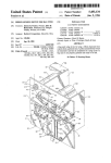
FIGS. 4A-4E represent a second physical embodi
ment for implementing the method of the invention.
pixels having a difference in gray scale of a ?rst
predetermined amount; and,
This second embodiment is a hard or dedicated circuit
d. selectively making a second predetermined number
of second comparisons of corresponding near
designed speci?cally to implement the method of the
invention.
10
Dedicated circuit 30 comprises I/O channel socket
49, which interconnects with an image processing inter
face board (e.g., DT2803, available from Data Transla
tion, Inc., or equivalent) to accept digitized video sig
neighboring pixels from said ?rst and second digi
tal representations if and only if no signi?cant dif
ference in ambient light intensity exists between
said ?rst and second visual images,
e. and indicating an alarm condition when a second
nals which are stored in the 64 k random access memory 15
(RAM) on the board. RAMs 35 and 36 are used to store
the old frame image signals for later comparison with
the new signals stored in memory on the interface
board. RAMs 35 and 36 comprise 64 k of memory
percentage of said second predetermined number
of second near neighboring comparisons result in
pixels having a difference in gray scale of a second
predetermined amount.
(43256-lOL, or equivalent). Erasable programmable
read-only memory (EPROM) 34 (27C256-20, or equiva
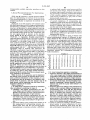
2. A method as described in claim 1 wherein said
second predetermined amount of difference in gray
scale is de?ned as “K2” and K2 is determined automati
lent) is used to store the control program, similar to
ALARM-U or ALARM-S used in the ?rst embodi
light within the visual images being compared in said
cally based on an average gray scale value of ambient
ment. Central processing unit 32 (8088 or equivalent)
?rst comparison, wherein said average gray scale value
controls the operations of the entire circuit. Latches 38, 25 is de?ned as “AGA”, and wherein the average gray
39 and 40 (74LS373 or equivalent) are used to latch the
scale of the ambient is determined by adding all of the
address signals A0, A1, . . . A19, and send them to the
individual gray scales values (GS) of each considered
appropriate chips as required. Bus transceiver 41
pixel and then dividing this total by the number of pixels
(74LS245 or equivalent) is used to transmit and receive
considered wherein K2 is determined according to
data signals. Clock generator 31 (8284 or equivalent)
Table I herebelow:
produces CLK and OSC signals to synchronize the
TABLE I
whole system. Programmable input/output interface
AGA
l
2
3
4
5
6
7
8
9
10
chip 42 (8255A or equivalent) is used to input the man
K2
1
2
4
7
9
l2
l4
l6
l6
l6
ual sensitivity setting (using BCD switches 51 and 52
AGA
ll
l2
l3
14
15
l6
l7
l8
19
20
and octad driver 43 [74LS244 or equivalent]) and to 35
Kg
l6
l6
l6
l6
l6
l6 l7
l7
l7
l7
output the sensitivity display (via 7 segment decoder?
drivers 44 and 45 [74ls47 or equivalent] to displays 53
and 54, respectively) and to send out alarm signals ANl
and AN2 which can drive buzzer 55 via driver 46
(74563 or equivalent) or other alarm devices via relays
RBI and R152 driven by driver 48 (74563 or equivalent).
The reset switch is used to reset the relays and sensitiv
ity switch 5; is used to select either manual sensitivity
(selected by BCD switches 51 or 52) or automatic sensi
tivity (selected by the software).
AGA
K2
AGA
K2
2l
l8
31
20
22
l8
32
20
23
l8
33
20
24
l8
34
2O
25
l8
35
21
26
l9
36
21
27
l9
37
21
28
l9
38
21
29
l9
39
21
30
l9
40
21
AGA
Kg
AGA
K2
51
26
61
30
S2
26
62
31
53
26
63
32
54
27
55
27
56
27
57
28
58
28
S9
29
60
29
3. A visual comparison apparatus, comprising:
45
a. means for obtaining a ?rst digital representation of
precise form of apparatus, and that changes may be 50
made therein without departing from the scope of the
a ?rst visual image, said ?rst digital representation
comprising a ?rst plurality of pixels, wherein each
pixel has a gray scale indicative of light intensity;
b. means for obtaining a second digital representation
of a second visual image, said second digital repre
sentation comprising a second plurality of pixels,
While the form of the apparatus used to implement
the method of the invention as described herein consti
tutes a preferred embodiment of this invention, it is to
be understood that the invention is not limited to this
wherein each pixel has a gray scale indicative of
invention as de?ned in the claims.
What is claimed is:
l. A visual image comparison method for automated
video surveillance, comprising the steps of:
light intensity;
c. means for selectively making a ?rst predetermined
55
number of ?rst remotely displaced comparisons of
a. obtaining a ?rst digital representation of a ?rst
corresponding pixels from said ?rst and second
visual image, said ?rst digital representation com
prising a ?rst plurality of pixels, wherein each pixel
ference in ambient light intensity exists between
has a gray scale indicative of light intensity;
b. obtaining a second digital representation of a sec- 60
0nd visual image, said second digital representation
comprising a second plurality of pixels, wherein
each pixel has a gray scale indicative of light inten
sity;
c. selectively making a ?rst predetermined number of 65
?rst comparisons of corresponding remotely dis
placed pixels from said ?rst and second digital
representations to determine whether a difference
digital representations to determine whether a dif
said ?rst and second visual images, wherein said
difference in ambient light intensity is de?ned to
exist when a ?rst percentage of said ?rst predeter
mined number of ?rst remotely displaced compari
sons result in pixels having a difference in gray
scale of a ?rst predetermined amount; and,
d. means for selectively making a second predeter
mined number of second comparisons of corre
sponding near neighboring pixels from said ?rst
and second digital representations if and only if no
11
5,151,945
12
signi?cant difference in ambient light intensity is
of second near neighboring comparisons result in
found to exist,
e. and indicating an alarm condition when a second
pixels having a difference in gray scale of a second
predetermined amount.
percentage of said second predetermined number
*
15
20
25
30
35
45
50
55
65
,
*
*
*
*