Download Ribbon sensing device for bag tyer
Transcript
lllllllllllllllllllllllllllllllllllllllllllllllllllllllllllllllllllllllllll
USOO5483134A
United States Patent [19]
[11] Patent Number:
Frazier et al.
[45]
[54] RIBBON SENSING DEVICE FOR BAG TYER
Date of Patent:
[56]
U'S' PATENT DOCUMENTS
Richardson, Oklahoma City; Greg R
Coxsey, Norman, all of Okla.
3,059,670 10/1962 Burford et al. .
3,138,904 6/1964 Burford .
3,919,829
Assignee: Burford Corporation, Maysville, Okla.
[21] APPL N0-3 129,284
[22] Filed:
Sep_ 30, 1993
Jan. 9, 1996
References Cited
[75] Inventors: Jimmy R. Frazier, Norman; John D.
[73]
5,483,134
11/1975 Burford et al. ......................... .. 53/135
4,277,731
7/1981 Pongracz ....... ..
4,856,258
8/1989 Burford et al. ..................... .. 53/138 A
318/562 X
Primary Examiner-David S. Martin
Attorney, Agent, or Firm—Crutsinger, Booth & Kanz
[51]
int. ciP ..................................................... .. GOSB 5/00
[57]
[52]
US. Cl. ........................ .. 318/468; 318/626; 318/640;
A bag neck tying device for tying a ribbon dispensed from
53/ 138.8; 53/583
a spool about a gathered neck. A pulley and proximityv switch
[58]
Field of Search ............................... .. 53/l38.l—138.3,
53/138.6—l38.7, 138.8, 139.4, 583, 203;
318/560, 561, 567, 568.1, 569, 626, 445,
449—450, 466—470
ABSTRACT
are mounted to prevent the completion of a tying cycle if a
bag neck is not properly gathered and ready to be tied.
10 Claims, 13 Drawing Sheets
US. Patent
Jan. 9, 1996
Sheet 1 of 13
5,483,134
US. Patent
Sheet 2 of 13
Jan. 9, 1996
5,483,134
com
'5
,
V3
K\
m.UE
US. Patent
Jan. 9, 1996
Sheet 3 of 13
5,483,134
FIG.3
US. Patent
Jan. 9, 1996
Sheet 4 of 13
M1
FIG. 4
5,483,134
U.S. Patent
Jan. 9, 1996
Sheet 5 of 13
E1
5,483,134
16
30
44
/‘
40
42
31
24
22
45
80
34
33
58
55
18
38
FIG. 5
US. Patent
Jan. 9, 1996
Sheet 6 of 13
5,483,134
6FIG.
US. Patent
Jan. 9, 1996 '
Sheet 7 of 13
5,483,134
/-90
8V DC
DC
I
f 94
6
60
i
,/
75a
O
O
x
62
TTTm
4@wjlLJ
M
\
@
E
T.>R16m
sN
FM
mm
3 mB
\ElZl__f
I H
FIG. 7
Y
i
4
I) q;
O
K
0 \El
llm
US. Patent
Jan. 9, 1996
Sheet 11 of 13
5,483,134
2600
2400
2000
1800
1600
1400
1200
1000
/
800
RPM
NEEDLE]
600
400
200
—200
KSHEAR
—600
—800
—1000
~1200
—1400
—l600
0
.02 .04 .06
.08
.10 .12
.14 .16 .18 I .20 .22
24
.26
.28
SECONDS
FIG. 11
.30
US. Patent
Jan. 9, 1996
Sheet 12 of 13
415
‘in mm’
5,483,134
US. Patent
Jan. 9, 1996
Sheet 13 of 13
5,483,134
FIG. 14
5,483,134
1
2
RIBBON SENSING DEVICE FOR BAG TYER
gathered materials in addition to the speci?c disclosed
embodiment of the bag neck tying device.
TECHNICAL FIELD
DESCRIPTION OF THE DRAWINGS
The invention relates to apparatus for wrapping a ribbon
around the gathered neck of a bag and twisting the ribbon for
closing and sealing the neck of a ?exible bag.
Drawings of a preferred embodiment of the invention are
annexed hereto so that the invention may be better and more
fully understood, in which:
BACKGROUND OF INVENTION
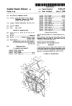
FIG. 1 is a perspective view illustrating the front of the
bag neck tying device;
U.S. Pat. No. 3,138,904 to Earl E. Burford entitled
“METHOD AND APPARATUS FOR TYING PACKAGES
AND WRAPPING MATERIALS;” U.S. Pat. No. 3,059,670
FIG. 2 is a diagrammatic front elevational view;
FIG. 3 is a diagrammatic rear elevational view;
FIG. 4 is an end view looking generally in the direction
of the arrows along line 4-4 in FIG. 2;
FIG. 5 is a diagrammatic end view illustrating the dis
to Charles E. Burford and Leonard W. Burford entitled
“WIRE TWISTING TOOL;” U.S. Pat. No. 3,919,829 to
Leonard W. Burford and Charles C. Burford entitled “APPA
RATUS FOR TYING PACKAGES AND WRAPPING
charge end of the bag neck tying device, looking in the
MATERIALS;” and U.S. Pat. No. 4,856,258, which issued
Aug. 15, 1989 to Charles E. Burford and Jimmy R. Frazier
entitled “WIRE TYING DEVICE” disclose apparatus used
direction of the arrows along line 5-5 in FIG. 2;
FIG. 6 is a top plan view, looking in the direction of the
arrows along line 6—6 in FIG. 2, parts being broken away
to more clearly illustrate the details of construction;
FIG. 7 is a wiring diagram of the closed loop microcom
for closing a plastic bag by attaching and twisting a wire-like
ribbon about the neck of the bag.
Bag tying devices of the type disclosed in the aforemen
tioned patents are commercially available from Burford
Corporation of Maysville, Okla. The tying devices are
generally constructed to receive packages such as loaves of
puter controlled control system;
25
FIG. 8 is a schematic diagram of the full wave recti?ed 8
and 34 volt power supply;
FIG. 9 is a schematic diagram of a bi-directional DC
motor controller;
careful consideration of the mass, acceleration, deceleration
FIG. 10 is a schematic diagram of a single direction DC
and momentum of the moving parts of the tying device. 30 motor controller;
Further, precise synchronization of parts in subassemblies of
FIG. 11 is a graphic representation of the sequence of
the tying devices must be maintained throughout a tying
operation of the needle, hook and shear assemblies during a
bread at speeds of for example one hundred (100) packages
per minute. The design of the bag tying devices requires
cycle if the device is to operate effectively.
SUMMARY OF INVENTION
complete cycle of operation;
FIG. 12 is a diafframatic front elevational view of the
35
The bag neck tying device disclosed herein incorporates
a bag neck gathering mechanism comprising motor driven
gathering belts for moving a bag neck along a path in a plane
into engagement with a bag stop controlled by an electric
brake positioned adjacent a ribbon holder-shear assembly
proximity switch; and
FIG. 14 is a perspective view of a holder-shear assembly.
Numeral references are employed to designate like parts
which holds the free end of a ribbon of tie material. A motor
driven needle wraps the strand of tie material around the
gathered neck of the bag, and a motor driven twister hook
assembly engages the free end and the running end of the
ribbon adjacent the gathered neck for twisting the ribbon.
Independently controlled bi-directional, brush type ser
throughout the various Figures of the drawing.
45
numeral 10, in FIGS. 1 and 2 of the drawing is mounted
adjacent the side of a conveyor 300 of the type disclosed in
Burford U.S. Pat. No. 3,138,904 and Burford U.S. Pat. No.
3,919,829, the disclosures of which are incorporated herein
by reference in their entirety for all purposes. Conveyor 300
carries for example, loaves 125 of bread to, through and out
of wire tying device 10 in rapid succession. Conveyor 300
tying device. Each of the servomotors is controlled by a
solid state DC motor controller in a closed loop feedback
system under the control of a multi-channel microcontroller
which precisely starts, controls and stops each of the ser
vomotors in a pre-assigned sequence for each cycle of the
tying apparatus.
55
the software driven motor controllers isolate the movement
further structures may form the conveyor.
60
material, such as plastic bag material or a variety of other
materials such as coils of electrical cord, water hose, tubing,
yarn, and bundles of cable, rods, or carrots, and in apparatus
for fastening the gathered material. It is contemplated that
the disclosed closed loop control circuit may be used to
control electric motors to drive apparatus for fastening
is well known to persons skilled in the art and further
description thereof is not deemed necessary except in con
nection with the drive mechanism as will be hereinafter
more fully explained. It should be appreciated that other and
of the various components of the tying device to reduce
stress and shock loading of parts of mechanical drive trains.
A preferred embodiment of the apparatus for securing
material includes improvements in apparatus for gathering
DESCRIPTION OF A PREFERRED
EMBODIMENT
The wire tying device, generally designated by the
vomotors are mounted in the separate :subassemblies of the
The weight and number of moving parts in the tying
device have been signi?cantly reduced. More particularly,
tying device with belt guards and covers in position, illus
trating a spool of ribbon;
FIG. 13 is a diaffrarnatic perspective view of a pulley and
65
Referring to Figure I of the drawing, the numeral 20
generally designates a bag gathering apparatus for moving a
bag 125 along a path 12 to a position adjacent a needle
assembly 40, a twister hook assembly 50 and a holder-shear
assembly 60. As will be hereinafter more fully explained, the
free end of a ribbon of wire-like material 15 is gripped in
holder-shear assembly 60. The neck of the bag moves
through a slot 122 between upper face plate 16 and lower
5,483,134
3
4
face plate 17 for drawing the bag 125 to a controlled tension
about the contents thereof. Needle assembly 40 wraps the
ribbon 15 of the wire-like material about the gathered neck
of the bag and twister hook 50 is actuated for twisting a
portion of the wire-like material about the neck of the bag
125. It should be noted that the ribbon of material 15 may
pulleys 36, 37 and 38. As best illustrated in FIG. 1 of the
be constructed of wire enclosed in paper or plastic or it may
comprise a ribbon of plastic or any other material. The strand
of ribbon 15 extends around one or more pulleys 41, 41a and
41b mounted on shafts 41a’ from a spool 41c of tie material,
as best illustrated in FIG. 12.
The mounting for spool 41c is similar to that disclosed in
US. Pat. No. 3,919,829 entitled “APPARATUS FOR
TYING PACKAGES AND WRAPPING MATERIALS”,
the disclosure of which is incorporated herein by reference
in its entirety for all purposes. However, it will be noted that
spool 410 of tie material is mounted on a shaft and tie
material 15 is fed from spool 14c and is routed around rollers
41b, 41a and 41, around needle roller 44 and the end of the
ribbon 15 is gripped in the holder-shear assembly 60, as best
illustrated in FIGS. 1 and 14 of the drawing. Spool 41c is
mounted on a shaft engaged by a brake (not shown). As
needle 42 forms a loop of tie material around the gathered
neck of a bag, the force of inertia and force exerted by the
brake cause the spool 41c to remain stationary momentarily
drawing, the portion 29 of the upper gathering belt 22,
extending between idler pulleys 27 and 2.8, is substantially
parallel and closely spaced relative to the portion 39 of the
lower gathering belt 32 which extends between driven
pulley 34 and idler pulley 36. In the illustrated embodiment,
gathering belts 22 and 32 move a bag neck along path 12 in
a plane P as illustrated in FIG. 2. A pressure pad 21,
resiliently urged upwardly by springs 21a and 21b acting
10
through bell cranks, maintains belts 22 and 32 in frictional
engagement with the neck of a bag or other material to be
tied.
As best illustrated in FIGS. 3 and 5 of the drawing, driven
shaft 25, having driven pulley 24 mounted on one end, has
a pulley 23 mounted on its opposite end. Driven shaft 35,
having driven pulley 34 mounted on one end, has a pulley
33 mounted on its opposite end. A pulley 30 mounted on the
drive shaft of motor M1 drives pulleys 23 and 33 through a
belt 31 such that driven pulley 24 rotates in a clockwise
20
direction while driven pulley 34 rotates in a counterclock
wise direction, as viewed in FIG. 2 of the drawing. Belt
guards 16a and 16b and 17a preferably extend between the
gathering belts and products on the conveyor, as illustrated
in FIG. 12. The bag neck is moved into a slot in the belt
as a crank arm, on which roller 41a is mounted, is rotated in 25
guard by brushes (not shown) and the product in the bag
a clockwise direction as illustrated in FIG. 12 of the draw
engages the belt guards when the neck of the bag is drawn
mg.
As will be herein;after more fully explained, one of the
pulleys 41, 41a or 41b is preferably equipped with a sensor
device which is capable of calculating the amount of ribbon
15 dispensed from spool 41c. The sensor apparatus deter
mines whether or not a bag neck is present. As needle 41
moves from the full outline position illustrated in FIG. 2 to
the dashed outline position, if a bag neck is not positioned
in the path of the ribbon, the cycle of operation will be
interrupted so that the holder-shear assembly 60 will not be
actuated and the twister hook assembly 50 will not rotate.
This prevents actuation of the holder-shear assembly which
would have resulted in the ribbon being dropped or released
by gathering belts 22 and 32 around a bag stop lever 80. It
should be appreciated that other and further gathering struc
30
clockwise,
counter
when used in reference to the drawings, generally refer to
orientation of the parks in the illustrated embodiment and
35
not necessarily during use. These terms used herein are
meant only to refer to relative positions and/or orientations,
for convenience, and are not to be understood to be in any
manner otherwise limiting.
As illustrated in FIGS. 7 and 10 of the drawing, motor M1
is driven by a solid state DC motor controller 91 which is
The frame of the bag tying device may assume many
con?gurations. In the illustrated embodiment upper and
lower face plates 16 and 17 are supported on forward edges
capable of varying the speed of motor M1 to substantially
synchronize movement of upper gathering belt 22 and
lowering gathering belt 33 with the speed of a conveyor 300
of vertically extending end plates 18 and 19 having slots
moving packages 125 adjacent the bag gathering mechanism
formed therein to permit passage of a bag neck. A horizontal
45
outwardly from end plate 18.
A motor M1, having an encoder E1 mounted the rear end
of motor M1, is mounted on an upper portion of the vertical
mounting plate 16a for driving the gathering assembly 20. A
Terms such as “left,” “right,
clockwise,” “horizontal,” “vertical,” “up,” and “down.”
if a bag neck was not present.
mounting plate 19a extends between lower portions of end
plates 18 and 19 and a vertical mounting plate 16a extends
tures may be used to form a gathered neck on a bag.
50
20. For example, if the tier 10 is to gather and tie the necks
of 100 bags per minute, the conveyer 300 would preferably
bring bags to and through the tier at a speed of approxi
mately 300 feet per minute and the gathering belts 22 and 32
would preferably be driven at a speed of, for example 305
feet per minute, so that the neck of the bag would be
accelerated for gathering the neck, stopped momentarily
motor M2, having an encoder E2 mounted the rear end and
a gear box 46 mounted on the front end of motor M2, is
mounted on an upper portion of the rear surface of face plate
while it is being tied with a ribbon and then discharged in a
substantially continuous operation.
16 for driving the needle assembly 40. A motor M3, having
As will hereinafter be more fully explained, the gathering
an encoder E3 mounted the rear end of motor M3, is 55 assembly 20 also includes a bag stop lever 80, illustrated in
mounted vertically on horizontally extending mounting
FIGS. 2 and 3, mounted on shaft 85 for rotary movement
plate 19a for driving the twister hook assembly 50. A motor
about a horizontal axis, in the illustrated embodiment. Shaft
M4, having an encoder E4 mounted the rear end of motor
85 extends through an electric brake 82, which momentarily
M4, is mounted on a lower portion of end plate 18, and in
the illustrated embodiment extends below motor M2, for
driving the holder-shear assembly 60.
Referring to FIGS. 1-5 of the drawing, bag neck gather
ing apparatus 20 comprises, in a preferred embodiment of
the invention, an upper gathering belt 22 routed around a
driven pulley 24 and idler pulleys 26, 27 and 28. The bag
neck gathering mechanism 20 further comprises a lower
gathering belt 32 routed around a driven pulley 34 and idler
65
locks lever 80 in a lowered position extending across path 12
such that gathering belts 22 and 32 move the bag neck into
engagement with lever 80. After the bag neck has been
gathered and tied, the electric brake 82 is released and the
gathered neck, carried between belts 22 and 32, urges the
lever 80 upwardly such that it does not obstruct movement
of the gathered neck. After the gathered neck passes lever
80, the lever 80 moves back to the illustrated position
extending across path 12.
5,483,134
5
6
A needle assembly 40, best illustrated in FIGS. 1-4 and 7,
is positioned for wrapping a strand 15 of ribbon material
around a gathered neck of a bag. The needle assembly 40
comprises a needle 42 carrying idler rollers 44, 44a and 44b.
FIG. 2 of the drawing. If needle 42 did not wrap ribbon
around a bag neck, the CPU will terminate a portion of the
remainder of the cycle of operation so that holder-shear 65
will not be actuated to prevent releasing the end of ribbon 15
which is gripped between gripper ?nger 64 and anvil 68 or
The needle 42 is mounted on the output shaft 45 of a gear
box 46 driven by motor M2. Needle 42 is shown in its home
position in FIGS. 1 and 2 of the drawing. Motor M2 moves
needle 42 from the full outline position to the dashed outline
position, illustrated in FIG. 2 of the drawing, and then
reverses for moving the needle 42 back to the position
illustrated in full outline in FIG. 2.
Referring to FIGS. 1, 3 and 7 of the drawing, a twister
69.
Referring to FIGS. 1, 2 and 3 of the drawing, a bag stop
lever 80 is mounted on a shaft 85 for rotary movement about
a horizontal axis. Shaft 85 extends through an electric brake
82 and has a crank arm 85a secured thereto which is
resiliently urged in a clockwise direction, as viewed in FIG.
hook assembly 50 comprises a twister shaft 52 rotatably
3, by a spring 83.
mounted in a bearing 53 having a hook 54 on one end thereof
and a pulley 55 on the other end. A drive pulley 56 is
mounted on the drive shaft of motor M3 and drives pulley
A switch 86 is actuated by switch arm 88, which actuates
a timer for energizing electric brake 82 which momentarily
locks bag stop 80 in a ?xed position for a predetermined
55 through a belt 58.
period of time, for example 0.25 seconds for restraining the
leading edge of a bag neck, such that gathering belts 22 and
32 will gather the neck adjacent bag stop 80. At the
expiration of the predetermined period of time, electric
As best illustrated in FIGS. 1, 2, 5, 7 and 14 of the
drawing, a ribbon holder-shear assembly, generally desig
nated by the numeral 60, comprises a holder and shear
assembly of the type disclosed in Design US. Pat. No.
307,281 to Charles E. Burford and US. Pat. No. 4,856,258
20
brake 82 will be de-energized so that linear movement of the
a gripper ?nger 64 on one end thereof rotatably secured to 25
bag neck will rotate bag stop 80 upwardly to release the bag
so that it will be moved away by the conveyor. Bag stop 80
is biased toward the position illustrated in FIG. 3 of the
drawing by a spring 83. It should be readily apparent that the
spring 83 may be replaced by a counter-weight, air cylinder
or other suitable biasing mechanism to resiliently urge bag
stop 80 toward its home position.
Motors M1, M2, M3 and M4 are bi-directional, perma
nent magnet, DC brush-type servomotors having outputs
entitled WIRE TYING DEVICE, which issued Aug. 15,
1989, to Charles E. Burford and Jimmy R. Frazier. The
holder~shear assembly 60 comprises a gripper arm 62 having
a mounting plate 66 by bolt 65. A pair of anvils 68 and 69
are formed on the end of mounting plate 66, each being
associated with shear surfaces 68a and 69a to grip and cut
a strand of ribbon as will be hereinafter more fully
explained.
30
Referring to FIGS. 5 and 7 of the drawing, a cam 70 is
mounted on the shaft of motor M4 and is con?gured to
engage cam-followers 72 and 74 on spaced arms 71 and 73
proportional to the voltage applied across the armatures.
Such motors are commercially available from Groschopp,
Inc. of Sioux Center, Iowa as a “Power Master 8304” 24 volt
DC continuous power motor. At 1500 rpm the motor gen
secured to and actuating rod 75 mounted for reciprocating
erates l6 oz-in torque and has an output of 0.090 horsepower
35
movement in bearings 76. A link 75a secures the end of
at 4.2 amps. At 2450 rpm the torque is 47 oz-in and the
gripper arm 62 to actuating rod 75.
It should be readily apparent when the shaft of motor M4
output is 0.113 horsepower at 5 amps. At 5400 rpm the
torque is 37 oz-in and the output is 0.197 horsepower at 8.2
rotates one-half revolution, cam 70 will exen force through
amps.
It is noted that other motors and motors of other sizes may
cam-followers 72 and 74 for moving actuating rod 75 for
pivoting the actuating arm 62 about bolt 65. The free end of
the ribbon is gripped between the end of gripper ?nger 64
and anvil 68 or 69, depending on which direction the gripper
?nger 64 is shifted. As will be hereinafter more fully
explained, when needle 42 wraps the intermediate section of
the ribbon 15 around the gathered neck of a bag, the ribbon
will be positioned between gripper ?nger 64 and the other
anvil 68 or 69. When gripper ?nger 64 is shifted to its
opposite position, the ribbon will be cut and the free end of
the strand of ribbon will be gripped between gripper ?nger
be provided to facilitate driving the various assemblies. For
example, it is contemplated that smaller motors would be
used in a counter top model used for gathering and fastening
materials such as coils of electrical cord, water hose, tubing,
or yarn, and bundles of cable, rods, or carrots and other
produce.
One side of the armature winding of each motor M1, M2,
M3 and M4 is connected to ground such that reversing the
polarity of current through the armature winding reverses
the direction of rotation of the motor.
Each of the motors M1, M2, M3 and M4 has an encoder
E1, E2, E3 or E4 mounted on its drive shaft which delivers
64 and anvil 68 or 69.
Referring to FIGS. 12 and 13 of the drawing, roller 41 has
a plurality of index points 41x. In the illustrated embodi
ment, the index points are formed by steel dowel pins
circumferentially spaced around the axis about which roller
an electrical signal to a decoder D1, D2, D3 or D4 which is
representative of the position of the motor shaft.
55
41 rotates.
MOTOR CONTROLLER
A proximity switch 41s is positioned near index pointers
41x for making an electrical circuit when the presence of an
Referring to FIGS. 7 and 8 of the drawing, the numeral 90
indexing pin 41x is sensed. The proximity switch 41s is of
conventional design and is connected through a suitable
power supply and ampli?er to the CPU 96.
Thus, the CPU monitors the proximity output and counts
the pulses produced by index pins 41x in roller 41. The CPU
generally designates a power supply for delivering electric
60
current to motor controller 91 and to motor M1 in the bag
whether or not a bag neck is present as needle 42 moves 65
neck gathering mechanism 20; motor controller 92 and
motor M2 in the needle assembly 40; motor controller 93
and motor M3 in the twister assembly 50; and motor
controller 94 and motor M4 in the holder-shear assembly 60.
Referring to FIG. 8 of the drawing, the power supply 90
96 calculates the amount of ribbon dispensed to determine
from the full outline position illustrated in FIG. 2 of the
drawing toward the dashed outline position illustrated in
comprises a pair of single-phase, doughnut transformers T1
connected in parallel. The supply or primary circuits of
5,483,134
7
8
transformers T1 are connectable to any suitable source of
modulated light into a silicon detector.
electricity such as 115 volt, 60 cycle, single-phase electric
ity. The energy receiving or secondary circuits of transform
tion elements for two or three channels. Each channel
The encoder body contains the phase plate and the detec
ers T1 are connected through one or more recti?er bridge
consists of an integrated circuit with two photo~diodes and
circuits B1 and B2 and capacitors C6 and C7 to a pair of
controlled voltage power terminals, one of which forms a
ampli?ers, comparator, and output circuitry (not shown).
The apertures for the two photo-diodes are positioned so
that a light period on one detector corresponds to a dark
source of direct current maintained at positive 34 volts and
the other a source of direct current at negative 34 volts.
An eight volt direct current power supply is illustrated in
FIG. 8 of the drawing. The eight volt power supply com
prises a pair of terminals connectable to the positive and
period on the other. The photo-diode signals are ampli?ed
10
. second channel has a similar con?guration but the location
negative 34 volt terminals of power supply 90 through
resistors R13 and R24 to positive and negative 8 volt
terminals. Apair of diodes Zenier D15 and D20 are provided
in the 8 volt power supply between resistors R13 and R24
and a ground terminal.
15
20
25
ENCODERS
Conventional multichannel incremental optical encoders
30
M1, M2, M3 and M4, respectively. The encoders E1—E4 are
high resolution incremental optical devices which include an
encoder body, a metal code wheel and emitter end plate. An
HEDS-6000 series, two and three channel incremental
optical encoder kits are available from Hewlett Packard of
Palo Alto, Calif. A standard selection of shaft sizes and
resolutions between 192 and 1024 cycles per shaft revolu
tion are available. The part number for a standard two
channel encoder is HDS-6000, while that for the three
channel device, with index pulse, is HEDS-60l0. The
encoder devices are typically used for printers, plotters, tape
by using the index pulse output only or by logically relating
the index pulse A and B data channels. The index pulse can
be uniquely related to the A and B data tracks in a variety of
ways. Statewidth, pulse width or edge transitions can be
used.
The two square wave signals in quadrature of channels A
and B and a 5 volt supply input are delivered through a
lO-pin connector to a corresponding decoder D1, D2, D3 or
D4 mounted on an auxiliary board, as illustrated in FIG. 7
of the drawing. Lines connecting encoders E2 to a decoder
DECODERS
35
Quadrature decoders D1—D4 are CMOS (complimentary
metal-oxide semiconductor) integrated circuits that perform
phase plate into a bifurcated detector lens (not shown).
The light is focused onto pairs of closely spaced inte
grated detectors which output two square wave signals in
quadrature and an optional index pulse.
The motion sensing application and encoder interface
circuitry will determine the need for relating the index pulse
to the vmain data tracks. A unique shaft position is identi?ed
D2 are illustrated. Encoders E3 and E4 are similarly con
nected to decoders D3 and D4.
E1, E2, E3 and B4 are mounted on the shaft of each motor
LED source and lenses transmit collimated light from the
emitter diode through a precision metal code wheel and
of its aperture pair provides an output which is in quadrature
to the ?rst channel (phase difference of 90°). Direction of
rotation is determined by observing which of the channels is
the leading waveform. The outputs are TFL logic level
signals.
The recti?ers in bridge circuits B1 and B2 are conven~
tior‘ral MB 352 recti?ers. Capacitors C6 and C7 are, for
example 33,000 UF capacitors. Resistors R13 and R24 are
470 ohm, 2 watt resistors.
The 34 volt and 8 volt power supplies illustrated in FIGS.
7 and 8 are of conventional design and form no part of the
present invention except in combination with the other
elements of the control circuit. It should be appreciated that
many other DC power supplies may be used in lieu of those
illustrated in the drawing.
and fed to a comparator whose output changes state when
the difference of the two photo currents changes sign. The
40
the quadrature decoder, counter, and bus interface functions.
“HTCL-ZOOO,” commercially available from Hewlett Pack
ard, quadrature decoder/counter interface IC decoder inter
faces an encoder to a microprocessor and is designed for use
in digital closed loop motion control systems and digital data
input systems.
45
The decoder includes a 4X quadrature decoder, a binary
up/down state counter and a 16-bit bus interface. A Schmitt
triggered CMOS input and input noise ?lters are incorpo
rated in the device.
Further information regarding the quadrature decoder/
counter interface IC for interfacing to Motorola and Intel
drives, positioning tables, automatic handlers, robots, and 50 microprocessors can be found at page 1—61 through page
other servo loop applications. Speci?c details of construc
tion of the incremental optical encoder can be found in
Hewlett Packard Publication No. 5954-8420 (3/87) which is
incorporated herein by reference.
The incremental shaft encoder operates by translating the
1-76 of Hewlett Packard Publication for “HCTL-ZOOO,”
“HCTL2016,” “HCTL-2020.”
Decoders Dl-D4 have pins for a channel A and channel
B Schmitt-trigger inputs which accept the outputs from
55 quadrature encoders E1—E4. The two channels are prefer
rotation of a shaft into interruptions of a light beam which
ably 90“ out of phase.
are then output as electrical pulses. The light source is a light
emitting diode collimated by a molded lens into a beam of
CONTROLLER
parallel light. An emitter end plate contains two or three
similar light sources, one for each channel.
60
The system is controlled by a computer 95, illustrated in
The code wheel is a metal disc that has N equally spaced
FIG. 7, which receives and stores a set of instructions and
slits around its circumference. An aperture with a matching
then acts upon ‘the instructions in a predetermined and
pattern is positioned on a stationary phase plate. The light
predictable fashion. A microprocessor 96 is attached to a
beam is transmitted only when the slits in the code wheel
printed circuit board into which a thin layer of metal has
and the aperture line up; therefore, during a complete shaft 65 been applied and then etched away to form traces. The
revolution, there will be N alternating light and dark periods.
electronic components of the central processing unit are
A molded lens beneath the phase plate aperture collects the
attached to the board with solder so that they can change
5,483,134
10
upon the feedback concept for operation and the output
electronic signals through the etched traces on the board.
A suitable 32-bit integrated microcontroller 96 is the
MC68332 which is commercially available from Motorola,
PWM signals are forced to a pre-assigned function of the
reference input of the microcontroller of the central process
ing unit. The microcontroller 96 sends control PWM signals
determined by the programmed movements stored in RAM
Inc. of Schaumburg, Ill. as a product referred to as
“MC68332 SIM” System Integrated Module. A complete
documentation package of the MC68332 consists of the
memory in a pre-assigned order as a function of time after
switch arm 88 returns to its home position illustrated in FIG.
3. The control PWM signals are delivered to the control
circuit. Each encoder E1—E4, connected to the shaft of
motors Ml-M4, send quadrature signals to the decoders
D1~D4 that indicate the position of the shaft of each motor.
The control PWM signals delivered to each control circuit
C1-C4 are delivered to motor drivers 91-94. The quadrature
signals from decoders D1—D4 are read to adjust the control
(SIM 32UM/AD), MC68332 System Integration Module
User’s Manual, the (CPU32RM/AD), CPU32 Reference
Manual, and the (TPU32RM/AD), Time Processing Unit
Reference Manual. The MC68332 System Integration Mod
ule User’s Manual describes the capabilities, registers, and
operation of the MC68332 MCU. The CPU Reference
Manual describes the operation, programming and instruc
tion set of the CPU32 processor used in the MC68332. The
Time Processing Unit Reference Manual describes the
autonomous timer system used in the MC68332.
15
The MC68332 microcontroller 96 contains intelligent
peripheral modules such as the time processor unit (TPU)
which provides 16 rnicrocoded channels for performing
time-related activities for simple input capture or output
holder-shear mechanism 60 are substantially identical. One
side of the winding of each of the motors M2, M3 and M4
is connected to ground. Drivers 92, 93 and 94 deliver either
capture to complicated motor control or pulse width modu
positive or negative power to the other side of the motor
lation. High-speed serial communications are provided by
the queued serial module (QSM) with synchronous and
winding for drying motors‘ M2, M3 and M4 in opposite
directions. For example, when positive 34 volt direct current
is delivered to the winding of motor M2, its shaft is driven
asynchronous protocols available. Two kilobytes of fully
static standby RAM allow fast two-cycle access for system
and data stacks and variable storage with provision for
battery backup. Twelve chip selects enhance system inte—
PWM signals.
Drivers 92, 93 and 94, which control the delivery of
power to motors M2, M3 and M4, respectively, for control
ling the needle assembly 40, twister hook assembly 50 and
25
in a clockwise direction. If negative 34 volt direct current is
delivered to the winding of motor M2, its shaft will be driven
gration for fast external memory or peripheral access. These
modules are connected on-chip via an interrnodule bus
in a counter~clockwise direction.
(MB).
ering assembly 20, is similar to drivers 92, 93 and 94 except
The driver 91 for motor M1 connected to the bag gath~
?at pack that operates at a frequency of 16.78 MHz with a
that driver 91 is not provided with the capability of deliv
ering negative direct current because it is not necessary for
5 volt supply and is software programmable. It has 16
motor M1 to be driven in reverse.
The Mc68332 microcontroller 96 is a l32-pin plastic quad
30
independent programmable channels and pins. Any channel
Software is stored in FEEPROM memory on the CPU
can perform any time function including input capture,
board for controlling the acceleration, speed and position of
output compare or pulse width modulation (PWM).
35
control and derivative control in a dosed loop control
operation. The microcontroller 96 is initially programmed
40
system.
In addition to the microcontroller chip 96 on the CPU
board, random-access memory (RAM) integrated circuits 97
are used for storing values in distinct locations which can be
recalled or altered for storing the software which controls
45
the system. Since the values which are in RAM memory are
lost when the power of the computer is turned 01f, a battery
backup is provided. The microcontroller 96 processes digital
signals, such as the presence or absence of voltages, to
represent values.
SO
The CPU board is connected to an auxiliary board 98
through a connector header which carries data signals and
address signals. Driver circuits C1—C4, which generate pulse
width modulated (PWM) signals, are mounted on the aux~
iliary board along with the decoders D1-D4. The pulse
the shaft of each motor M1—M4. FIG. 11 is a graphic
representation of the sequence of operation of the needle,
hook and shear assemblies during a complete cycle of
The detailed logical procedures or algorithms processed
by the microcomputer are proportional integral derivative
(PID) type control mode signals. The PID control mode
combines the best action of proportional control, integral
55
width modulated signals from driver circuits C1—C4 are sent
to the motor drivers 91-94 selectively delivering positive or
negative DC power to control the operation of motors
M1—M4.
CLOSED LOOP
by a computer through a serial port RS for storing a program
which will initiate movement of needle 42 from its home
position illustrated in FIG. 3 and the speed of movement
toward the dashed outline position illustrated in FIG. 3
controlled by signals delivered through control circuit C2 to
motor M2. While needle 42 is moving from the position
illustrated in full outline toward the position illustrated in
dashed outline, the program causes a signal to be sent from
control circuit C3 to motor M3 to begin rotating twister hook
54 and continue rotation of twister 54 a predetermined
number of revolutions controlled by the motion pro?le in
RAM memory. Similarly, when needle 42 and twister hook
54 are in predetermined positions, a signal will be sent from
driver circuit C4 which will energize motor M4 for rotating
cam 70 to move the gripper ?nger 64 to release the free end
of the ribbon and shear a segment from the end of the strand
of ribbon. At a time controlled by the software, a signal will
be delivered to motor M2 for moving needle 42 from the
position shown in dashed outline in FIG. 3 back to its home
position. A signal will be delivered to motor M3 for rotating
twister book 54 two revolutions in the reverse direction for
slinging the tie, which has been twisted around the neck of
a bag, out of the twister hook 54 for completing a tying
cycle.
It should be readily apparent that when the neck of a bag
moves between gathering belts 22 and 32, switch arm 88
The circuits carrying input signals from the encoders
E1—EA to decoders D1-D4; the circuit carrying pulse width
will be moved downwardly from the position illustrated in
modulated signals from driver circuits C1—C4 to motor
motor drivers 91-94 to motors M1—M4 form a closed loop
FIG. 3 which will energize electric brake 82 so that belts 22
and 32 will move the neck of the bag into engagement with
control system. The closed loop control system depends
bag stop 80 causing the neck to be gathered. As the trailing
drivers 91—94; and the circuits carrying power from the
65
5,483,134
11
12
edge of the neck of the bag passes over the end of switch arm
88, switch arm 88 will move back to the position illustrated
in FIG. 3 causing switch 86 to send a signal to the micro
controller for starting a new tying cycle.
A schematic diagram of a motor controller 92 is illustrated
in FIG. 9 of the drawing. The optic coupler C0 delivers a
PWM signal to the positive terminal CH1 from driver circuit
C2 with reference to the negative terminal CH1.
The positive terminal CH1 is connected through resistor
R14, resistor R15 and diode D11 to the base terminal of high
rail MPS651 transistor Q7. The negative terminal CH1 is
connected through resistor R18 to the base of 2N2222A
transistor Q11 and through a 750 ohm resistor R92 to a
negative 8 volt terminal and to the emitter of transistor Q11.
low rail transistor Q9.
The low rail and high rail inhibit circuits IH and IL assure
that the control output voltage be zero before switching
occurs. The inhibit circuits protect the power transistors Q5
and Q13.
It is to be understood that while detailed descriptions of a
preferred embodiment has been illustrated and described,
the invention is not to be limited to the speci?c arrangement
10
embodied in various forms.
Having described the invention, we claim:
1. Bag neck tying apparatus comprising:
A 56 ohm resistor R22 forms a shunt between the base and
a pulley having index points;
emitter of transistor Q11. The collector of transistor Q11 is
a proximity switch mounted adjacent said pulley to indi
cate movement of said index points on said pulley;
connected between resistors R14 and R15.
The 1 ohm resistor R15 is connected through HMLPl700
diode D13 to the base of low rail MPS751 transistor Q9.
Transistor Q11 turns off and on to turn transistors Q7 and
Q9 off and on, which in turn, turn the high rail MJ 11033
power transistor Q5 and the low rail M] 11032 power tran
sistor Q13 off and on.
a source of ribbon for dispensing a strand of ribbon having
a free end and a central portion, said central portion of
ribbon extending around said pulley;
a holder-shear assembly for holding the free end of said
ribbon;
The collector of high rail transistor Q7 is connected
through a 300 ohm 5 watt resistor R11 to the base of high rail
25
power transistor Q5. The emitter of high rail transistor Q5 is
a needle assembly for engaging and positioning said
central portion of said ribbon adjacent said holder-shear
assembly;
a twister assembly having a hook adjacent said holder
connected to a +34 volt DC terminal while the collector of
power transistor Q5 is connected through an MR822 diode
D9 to a line connected to one side of the winding of motor
M2. The collector of low rail transistor Q9 is connected
of parts and speci?c features herein described and illustrated
in the drawing. Rather, the descriptions are merely of an
exemplary embodiment of the invention, which may be
shear assembly;
an electric motor having a drive shaft connected for
30
actuating said holder-shear assembly; and
through a 300 ohm 5 watt resistor R20 to the base of low rail
power transistor Q13. The emitter of low rail power tran
sistor Q13 is connected to a —34 volt DC terminal while its
a control circuit connected to said proximity switch and
said motor for controlling movement of said holder
collector is connected through MR822 diode D16 to the line
connected to one side of the winding of motor M2.
When the PWM signal, delivered to the terminals marked
prevent movement of said holder-shear assembly if
movement of index points on said pulley do not indi
shear assembly, said control circuit being con?gured to
35
cate that a su?icient amount of ribbon has been dis
CH1 is not conducting current, high rail transistor Q7 and
pensed from said source of ribbon.
high rail power transistor Q5 are turned on for delivering a
2. Bag neck tying apparatus according to claim 1, with the
positive 34 volt direct current to the motor winding causing
addition of:
an encoder connected to said drive shaft for generating
electrical signals related to the position of said drive
shaft, said control circuit comprising a closed loop
control circuit connected to said motor and said
motor M2 to tend to move in a clockwise direction. When
the PWM signal, delivered to the terminals marked CH1, are
conducting current, low rail transistor Q9 and low rail power
transistor Q13 are turned on for delivering a negative 34 volt
direct current to the motor winding causing motor M2 to
tend to move in a counter-clockwise direction. The ratio of 45
time in which the PWM signal is in either state determines
the direction and speed of the motor.
random access memory; and
software stored in said memory for generating a reference
To protect high rail power transistor Q5 and low rail
power transistor Q13 from being conducting air the same
time due to differences in manufactured component switch
ing times, high rail inhibit transistor Q17 disables high rail
transistor Q7 from turning on as long as low rail power
transistor Q13 is turned on.
Likewise low rail inhibit transistor Q1 inhibits low rail 55
transistor Q9 from turning on if there is a positive voltage at
the collector of high rail power transistor Q5 su?icient to
forward bias low rail inhibit transistor Q1.
The high rail inhibit circuit IH is connected from the
collector of the low rail power transistor through diodes D18
and D21 and resistor R29 to the base of high rail inhibit
input signal for controlling said motor.
3. Bag neck tying apparatus according to claim 2, said
closed loop control circuit comprising:
a feedback loop for forcing said reference input signal to
a predetermined value which is a function of the
position of said shaft.
4. Bag neck tying apparatus according to claim 2, said
encoder comprising:
a light source;
a code wheel having slits formed therein; and
a lens to focus and transmit collimated light from said
light source through slits in said code wheel to deliver
at least two square wave signals in quadrature.
transistor Q17. The emitter of high rail inhibit transistor Q17
is connected to the base of high rail transistor Q7. The low
rail inhibit circuit IL is connected from the collector high rail
power transistor Q5 through diodes D7 and D5 and resistor
R3 to the base of low rail inhibit transistor Q1. The emitter
of low rail inhibit transistor Q1 is connected to the base of
encoder;
a CPU having programmable read only memory and
65
5. Bag neck tying apparatus according to claim 2, said
electric motor comprising:
a bi-directional, permanent magnet, DC brush-type ser
vomotor having an armature and a drive shaft, said
drive shaft having output power that is proportional to


