1
User’s
Manual
DL850/DL850V
ScopeCorder
Real Time Math (/G3 option)
IM DL850-51EN
4th Edition
Thank you for purchasing this DL850/DL850V with the real time math (/G3) option. This user’s manual
explains the real time math feature.
Manual Title
DL850/DL850V ScopeCorder
Real Time Math (/G3 option)
User’s Manual
Manual No.
IM DL850-51EN
Description
This manual. The supplied CD contains the PDF file of
this manual. The manual explains the real time math
feature.
For information on other features, how to use these features, and handling precautions, see the
following manuals.
Notes
Manual Title
DL850/DL850V ScopeCorder
Features Guide
Manual No.
IM DL850-01EN
DL850/DL850V ScopeCorder
User’s Manual
DL850/DL850V ScopeCorder
Getting Started Guide
DL850/DL850V ScopeCorder
Communication Interface
User’s Manual
IM DL850-02EN
IM DL850-03EN
IM DL850-17EN
Description
The supplied CD contains the PDF file of this manual.
This manual explains all the DL850/DL850V features
other than the communication interface features.
The supplied CD contains the PDF file of this manual. The
manual explains how to operate the DL850/DL850V.
This manual explains the handling precautions and basic
operations of the DL850/DL850V.
The supplied CD contains the PDF file of this manual.
This manual explains the DL850/DL850V communication
interface features and how to use them.
• This manual covers firmware versions 1.35 and later of the DL850/DL850V.
• The contents of this manual are subject to change without prior notice as a result of continuing
improvements to the instrument’s performance and functionality. The figures given in this manual
may differ from those that actually appear on your screen.
• Every effort has been made in the preparation of this manual to ensure the accuracy of its
contents. However, should you have any questions or find any errors, please contact your nearest
YOKOGAWA dealer.
• Copying or reproducing all or any part of the contents of this manual without the permission of
YOKOGAWA is strictly prohibited.
• The TCP/IP software of this product and the documents concerning it have been developed/created
by YOKOGAWA based on the BSD Networking Software, Release 1 that has been licensed from
the Regents of the University of California.
Trademarks
• Microsoft, Internet Explorer, MS-DOS, Windows, Windows NT, Windows XP, and Windows Vista
are either registered trademarks or trademarks of Microsoft Corporation in the United States and/or
other countries.
• Adobe and Acrobat are either registered trademarks or trademarks of Adobe Systems Incorporated.
• In this manual, the ® and TM symbols do not accompany their respective registered trademark or
trademark names.
• Other company and product names are registered trademarks or trademarks of their respective
holders.
Revisions
•
•
•
•
1st Edition: March 2011
2nd Edition: July 2011
3rd Edition: February 2012
4th Edition: July 2012
4th Edition: July 2012 (YMI)
All Rights Reserved, Copyright © 2011, Yokogawa Meters & Instruments Corporation
IM DL850-51EN
Conventions Used in This Manual
Notes and Cautions
The notes and cautions in this manual are categorized using the following symbols.
Improper handling or use can lead to injury to the user or damage to the
instrument. This symbol appears on the instrument to indicate that the user must
refer to the user’s manual for special instructions. The same symbol appears
in the corresponding place in the user’s manual to identify those instructions.
In the manual, the symbol is used in conjunction with the word “WARNING” or
“CAUTION.”
WARNING
Calls attention to actions or conditions that could cause serious or fatal injury to
the user, and precautions that can be taken to prevent such occurrences.
CAUTION
Calls attention to actions or conditions that could cause light injury to the user
or cause damage to the instrument or user’s data, and precautions that can be
taken to prevent such occurrences.
Note Calls attention to information that is important for proper operation of the
instrument.
Unit
k
K
ii
Denotes 1000. Example: 100 kS/s (sample rate)
Denotes 1024. Example: 720 KB (file size)
IM DL850-51EN
Contents
1
Conventions Used in This Manual..................................................................................................... ii
1
2
3
IM DL850-51EN
Features
Digital Filter and Delay (Filter/Delay Setup)................................................................................... 1-1
Real Time Math (RealTime Math).................................................................................................. 1-4
Notes Regarding Using the Digital Filter and Real Time Math.................................................... 1-23
Configuring Digital Filter Settings
Digital Filter.................................................................................................................................... 2-1
Gauss............................................................................................................................................ 2-1
Sharp............................................................................................................................................. 2-2
IIR.................................................................................................................................................. 2-3
Mean.............................................................................................................................................. 2-4
2
3
4
5
Configuring Real Time Math Settings
Real Time Math Settings................................................................................................................ 3-1
Basic Arithmetic (S1+S2, S1−S2, S1*S2, and S1/S2)................................................................... 3-4
Basic Arithmetic with Coefficients (A(S1)+B(S2)+C, A(S1)−B(S2)+C, A(S1)*B(S2)+C, and A(S1)/
B(S2)+C)........................................................................................................................................ 3-4
Differentiation (Diff(S1))................................................................................................................. 3-4
Integration (Integ1(S1) and Integ2(S2))......................................................................................... 3-4
Angle of Rotation (Rotary Angle)................................................................................................... 3-5
Logic Signal to Analog Waveform Conversion (DA)...................................................................... 3-7
Quartic Polynomial (Polynomial).................................................................................................... 3-7
RMS Value (RMS).......................................................................................................................... 3-8
Effective Power (Power)................................................................................................................ 3-8
Effective Power Integration (Power Integ)..................................................................................... 3-9
Common Logarithm (Log1 and Log2)............................................................................................ 3-9
Square Root (Sqrt1 and Sqrt2)...................................................................................................... 3-9
Cosine (Cos) and Sine (Sin)........................................................................................................ 3-10
Arc Tangent (Atan)....................................................................................................................... 3-12
Electrical Angle (Electrical Angle)................................................................................................ 3-13
Knocking Filter (Knock Filter; only on the DL850V)..................................................................... 3-15
Polynomial with a Coefficient (Poly-Add-Sub)............................................................................. 3-15
Frequency (Frequency)............................................................................................................... 3-15
Period (Period)............................................................................................................................. 3-15
Edge Count (Edge Count)........................................................................................................... 3-16
Resolver (Resolver)..................................................................................................................... 3-16
IIR Filter (IIR Filter)...................................................................................................................... 3-17
Demodulation of the Pulse Width Modulated Signal (PWM)....................................................... 3-17
Reactive Power (Reactive Power(Q)).......................................................................................... 3-18
CAN ID Detection (CAN ID)......................................................................................................... 3-18
iii
App
Index
Contents
4
Commands
5
Error Messages
List of Commands.......................................................................................................................... 4-1
RMATh CHANnel Group................................................................................................................ 4-5
Messages...................................................................................................................................... 5-1
Execution Errors............................................................................................................................ 5-1
Setup Errors................................................................................................................................... 5-1
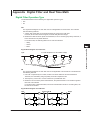
Appendix Digital Filter and Real Time Math
Digital Filter Operation Type...................................................................................................... App-1
Filter Features............................................................................................................................ App-2
About the Group Delay Characteristic....................................................................................... App-2
About the Calculation Frequency............................................................................................... App-3
About the Math Delay................................................................................................................ App-3
Sharp Filter................................................................................................................................ App-4
Gauss Filter............................................................................................................................. App-10
IIR (Butterworth)...................................................................................................................... App-12
Mean Filter............................................................................................................................... App-22
Real Time Math Differentiation................................................................................................. App-23
About the Electrical Angle........................................................................................................ App-24
Resolver................................................................................................................................... App-25
Math Flowchart and Internal Math Expressions of Real Time Math........................................ App-26
Index
iv
IM DL850-51EN
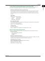
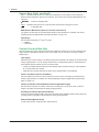
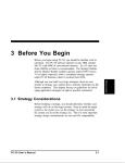
1
Features
1
/G3 option
16 channels
Plug-in
module
3
4
16 channels
GIGAZoom
Engine 2
16 channels
Real time math
Math operations
App
Trigger circuit
Real time math
ACQ memory
Index
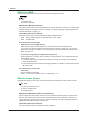
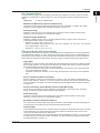
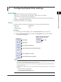
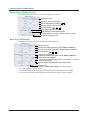
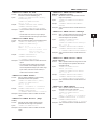
Digital Filter and Delay (Filter/Delay Setup)
You can set digital filters and delays on input channel waveforms (A/D converted data). This is one of
the features of the /G3 option.
• Configure the settings for each channel. You can perform filtering on up to 16 channels at the same
time.
• Even during waveform acquisition, you can set the filter type, filter band, and cutoff frequency.
• The digital filter/delay setup menu is displayed when the real time math menu is turned off.
• To enable the digital filter/delay feature and the real time math feature at the same time, you have to
first configure the digital filter/delay settings, and then turn the real time math menu on.
• You cannot set digital filters or delays on the bits or input channels of a logic, 16-CH voltage input,
16-CH temperature/voltage input, CAN bus monitor, or CAN & LIN bus monitor module.
• By setting the waveform that results from filtering as a trigger source, you can trigger the DL850/
DL850V on the results.
• For details on the digital filter characteristics, delay, and settings, see the appendix.
Bandwidth (Bandwidth)
When you set a filtering feature, it takes effect immediately.
• Digital (Digital): Select this item to display a menu for configuring the optional digital filter.
• LPF: Select this item to display a menu for configuring the standard filter.
For details on the standard filter feature, see the Features Guide, IM DL850-01EN.
IM DL850-51EN
2
5
Digital filter
16 channels
Digital filter/
delay
Features
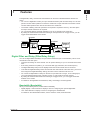
The digital filter, delay, and real time math features can be used on DL850/DL850Vs with the /G3
option.
• You can set a digital filter or delay on input channel waveforms (A/D converted data). You can also
perform real time math operations in which the waveforms of input channels or the results of other
real time math operations are used as the math source waveforms.
• The results of filtering and math operations are acquired in acquisition memory—the same place
that input channel waveforms are acquired.
• You can perform filtering and math operations on up to 16 channels at the same time.
• By setting the waveform that results from filtering or math operations as a trigger source, you can
trigger the DL850/DL850V on the results.
1-1
1 Features
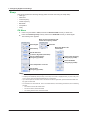
Filter Type (Filter Type)
The following digital filter types are available: Gauss, Sharp, IIR, and Mean. The features of each filter
are listed below.
Filter Type
Gauss
Sharp
IIR
Mean
Features
• Frequency characteristics with a smooth attenuation slope
• Linear phase and constant group delay
• No ripples present in the passband
• No overshoot in the step response
• Low order and short delay
•Frequency characteristics with a sharp attenuation slope
(–40 dB at 1 oct)
• Linear phase and constant group delay
• Ripples present in the passband
• Comb-shaped stopband
•Attenuation slope steepness between those of the SHARP and
GAUSS filters
• Non-linear phase and non-constant group delay
• No ripples present in the passband and stopband
• Characteristics similar to those of analog filters
•Compared to Sharp and Gauss filters, lower cutoff frequency
possible
• Comb-shaped frequency characteristics
• Linear phase and constant group delay
• No overshoot in the step response
Operation Type
FIR
FIR
IIR
FIR
Filter Band (Filter Band)
When the filter type is set to Gauss, Sharp, or IIR, you can select the filter band. The type of filter band
that you can select depends on the filter type.
Filter Type
Gauss
Sharp
IIR
Filter Band
Low-Pass
Low-Pass, High-Pass, Band-Pass
Low-Pass, High-Pass, Band-Pass
Cutoff Frequency (CutOff)
When the filter type is set to Sharp, Gauss, or IIR and the filter band is set to Low-Pass or High-Pass,
you can set the cutoff frequency. The ranges and resolutions are indicated below.
Filter Type
Gauss
Filter Band
Low-Pass
Sharp
Low-Pass
High-Pass
IIR
Low-Pass
High-Pass
1-2
Range
Resolution
0.002 kHz to 300 kHz 0.0002 kHz (0.002 kHz to 0.0298 kHz range)
Default value: 300 kHz 0.002 kHz (0.03 kHz to 0.298 kHz range)
0.02 kHz (0.30 kHz to 2.98 kHz range)
0.2 kHz (3.0 kHz to 29.8 kHz range)
2 kHz (30 kHz to 300 kHz range)
0.002 kHz to 300 kHz 0.0002 kHz (0.002 kHz to 0.0298 kHz range)
Default value: 300 kHz 0.002 kHz (0.03 kHz to 0.298 kHz range)
0.02 kHz (0.30 kHz to 2.98 kHz range)
0.2 kHz (3.0 kHz to 29.8 kHz range)
2 kHz (30 kHz to 300 kHz range)
0.20 kHz to 300 kHz
0.02 kHz (0.20 kHz to 2.98 kHz range)
Default value: 300 kHz 0.2 kHz (3.0 kHz to 29.8 kHz range)
2 kHz (30 kHz to 300 kHz range)
0.002 kHz to 300 kHz 0.002 kHz (0.002 kHz to 0.298 kHz range)
Default value: 300 kHz 0.02 kHz (0.30 kHz to 2.98 kHz range)
0.2 kHz (3.0 kHz to 29.8 kHz range)
2 kHz (30 kHz to 300 kHz range)
0.02 kHz to 300 kHz
0.02 kHz (0.02 kHz to 2.98 kHz range)
Default value: 300 kHz 0.2 kHz (3.0 kHz to 29.8 kHz range)
2 kHz (30 kHz to 300 kHz range)
IM DL850-51EN
1 Features
1
Center Frequency (Center Frequency)
Filter Type
Sharp
Range
0.30 kHz to 300 kHz
Default value: 300 Hz
IIR
0.06 kHz to 300 kHz
Default value: 300 Hz
Features
When the filter type is set to Sharp or IIR and the filter band is set to Band-Pass, set the center
frequency. The ranges and resolutions are indicated below.
Resolution
0.02 kHz (0.30 kHz to 2.98 kHz range)
0.2 kHz (3 kHz to 29.8 kHz range)
2 kHz (30 kHz to 300 kHz range)
0.02 kHz (60 Hz to 1.18 kHz range)
0.2 kHz (1.2 kHz to 11.8 kHz range)
2 kHz (12 kHz to 300 kHz range)
2
3
Bandwidth (Pass Band)
4
When the filter type is set to Sharp or IIR and the filter band is set to Band-Pass, set the bandwidth.
The bandwidth options vary depending on the center frequency that you have set. For details about
these options, see the appendix.
5
Tap (Tap)
When the filter type is set to Mean, select the number of taps (number of levels) from the following
options. The larger the number of taps, the sharper the filter characteristics become.
2, 4, 8, 16, 32, 64, 128
App
Mean Sample Rate (Mean Sample)
Index
When the filter type is set to Mean, select the sample rate from the following options. The specified
sample rate is used to sample waveforms and to filter them.
1 M, 100 k, 10 k, 1 k (unit: S/s)
Interpolation On and Off (Interpolate)
Select whether to perform data interpolation. Up to 10 M samples of data can be interpolated from the
data of waveforms that pass through the digital filter. The interpolation method is linear interpolation.
• ON: Data is interpolated.
• OFF:Data is not interpolated.
Delay (Delay)
You can set a delay on waveforms that pass through the digital filter.
The sampling data is decimated in a simple manner to produce the data delay. Consequently, if you
set a large delay, data updating automatically becomes slower. The default value is 0.0 μs.
Range
0.0 μs to 100 μs
101 μs to 1.00 ms
1.01 ms to 10.00 ms
Resolution
0.1 μs
1 μs
0.01 ms
Data Update Frequency
10 MHz
1 MHz
100 kHz
Note
The delay is valid even if you are not using the digital filter. However, if you set a delay, the sampling data
automatically passes through the digital filter circuit. Therefore, the actual delay when you are not using the
digital filter is 1.4 μs (the minimum math delay) + the set delay.
IM DL850-51EN
1-3
1 Features
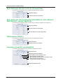
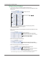
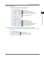
Real Time Math (RealTime Math)
Turning Real Time Math On and Off
Select whether to use real time math.
• ON: Select this item to display a menu for configuring real time math. At the same time, real time
math execution begins.
• OFF:Select this item to display a menu for configuring the standard model. Real time math is not
executed.
For details on the features of the standard model, see the Features Guide, IM DL850-01EN.
You can perform real time math operations in which the waveforms of input channels or the results of
other real time math operations are used as the math source waveforms. This is one of the features of
the /G3 option.
• Configure the settings for each channel. You can perform math operations on up to 16 channels at
the same time.
• When you turn real time math on, the real time math results are output to the real time math
channels (the channels that you have turned math on for). The waveforms of input channels that
you have turned math on for are not displayed. They are also not saved. For example, if you turn
real time math on for input channel CH2, CH2 becomes the RMath2 real time math channel, and
the math results are displayed on the screen. The data that is saved is that of the math result. If you
want to display and save the waveform of the input channel, set the real time math to a channel that
has no input.
• You can set the real time math source waveforms to the input channels of 16-CH voltage input,
16-CH temperature/voltage input, CAN bus monitor, and CAN & LIN bus monitor module, but you
cannot set the channel that the real time math result is output on to an input channel of a 16-CH
voltage input, 16-CH temperature/voltage input, CAN bus monitor, or CAN & LIN bus monitor
module (there is no menu for turning real time math on).
• For details on the modules whose channels you can set as real time math sources, see “Notes
Regarding Using the Digital Filter and Real Time Math” on page 1-23.
• Even during waveform acquisition, you can set various math conditions, such as the operator
or function (the operation definition), the source waveforms, and the coefficients. However, if
you change the conditions, the measurement count (waveform acquisition count) is reset. The
measurement count is displayed in the lower left of the screen. In roll mode during waveform
acquisition, real time math cannot be turned on and off.
• By setting the waveform that results from math operations as a trigger source, you can trigger the
DL850/DL850V on the results.
• For details on the math expressions, delay, and settings, see the appendix.
Labels (Label)
This is the same as the feature on the standard model. For details, see the Features Guide, IM DL85001EN.
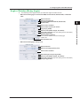
Real Time Math Setup (RealTime Math Setup)
Select an operator or function (operation definition), and then set its corresponding items.
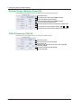
Operators and Functions (Operation)
•
•
•
•
•
S1+S2: Adds the waveforms assigned to Source1 and Source2
S1–S2: Subtracts the waveform assigned to Source2 from the waveform assigned to Source1
S1*S2: Multiplies the waveforms assigned to Source1 and Source2
S1/S2: Divides the waveform assigned to Source1 by the waveform assigned to Source2
A(S1)+B(S2)+C: Performs addition with coefficients on the waveforms assigned to Source1 and
Source2
• A(S1)–B(S2)+C: Performs subtraction with coefficients on the waveforms assigned to Source1
and Source2
• A(S1)*B(S2)+C: Performs multiplication with coefficients on the waveforms assigned to Source1
and Source2
• A(S1)/B(S2)+C: Performs division with coefficients on the waveforms assigned to Source1 and
Source2
1-4
IM DL850-51EN
1 Features
IM DL850-51EN
1-5
1
Features
• Diff(S1): Performs differentiation on the waveform assigned to Source using a fifth order
Lagrange interpolation formula
• Integ1(S1): Performs integration on the positive component of the waveform assigned to Source
• Integ2(S1): Performs integration on the positive and negative components of the waveform
assigned to Source
• Rotary Angle: Uses the waveforms or logic signals that have been assigned to phases A, B, and
Z to calculate the angle of rotation. This can be used to calculate the angle of rotation or the
displacement of an encoder.
• DA: Converts the logic signals that have been assigned to Source1 (the least significant digits)
and Source2 (the most significant digits) into an analog waveform and scales the results
• Polynomial: Performs a quartic polynomial calculation on the waveform that has been assigned
to Source
• RMS: Calculates the RMS value of the waveform that has been assigned to Source
• Power: Calculates the effective power of the waveforms that have been assigned to Source1 and
Source2
• Power Integ: Integrates the effective power of the waveforms that have been assigned to
Source1 and Source2.
• Log1: Calculates the common logarithm of the waveforms that have been assigned to Source1
and Source2 (the calculation is performed on “Source1/Source2”)
• Log2: Calculates the common logarithm of the waveform that has been assigned to Source
• Sqrt1: Calculates the square root of the sum (or difference) of the squares of the waveforms that
have been assigned to Source1 and Source2. This can be used to analyze displacement and
tolerance.
• Sqrt2: Calculates the square root of the waveform that has been assigned to Source
• Cos: Uses the waveforms or logic signals that have been assigned to phases A, B, and Z to
determine the angle, and then calculates the cosine of this angle. You can use this to convert the
angle to displacement.
• Sin: Uses the waveforms or logic signals that have been assigned to phases A, B, and Z to
determine the angle, and then calculates the sine of this angle. You can use this to convert the
angle to displacement.
• Atan: Calculates the arc tangent of the waveforms that have been assigned to Source1 and
Source2 (the calculation is performed on “Source1/Source2”). You can use this to convert the
displacement to an angle.
• Electrical Angle: Calculates the phase difference between (1) the angle that was determined from
the logic signals that were specified for phases A, B, and Z, and (2) the fundamental component
that was determined from the discrete Fourier transform of the waveform that was specified as
the target. You can calculate the phase difference (electrical angle) between the motor’s angle of
rotation and the motor drive current.
• Knock Filter (can only be set on the DL850V): When the signal level of the waveform that has
been set to Source is less than or equal to the elimination level, the signal of this waveform is set
to 0. You can select whether to perform differentiation. You can use this to extract knocking.
• Poly-Add-Sub: Performs addition or subtraction or both on the waveforms that have been set
to Source1, Source2, Source3, and Source4. You can add or subtract the result of the power
calculation, to calculate the multi-phase power.
• Frequency: Calculates the frequency of the waveform that has been assigned to Source
• Period: Calculates the period of the waveform that has been assigned to Source
• Edge Count: Counts the number of slope edges of the waveform that has been assigned to
Source. You can use this to count the number of events in consecutive tests.
2
3
4
5
App
Index
1 Features
• Resolver: Calculates the angle of rotation from the sine signal and cosine signal that are
generated from the detection coils of the resolver depending on the angle of the rotor.
• IIR Filter: This can be used to filter the waveform that has been set to Source with the same
characteristics of the IIR filter of the digital filter. You can set the frequency to values over a wider
range than is available with the IIR filter of a digital filter.
• PWM: Integrates a pulse width modulation signal and demodulates it to an analog signal.
• Reactive Power(Q): Calculates the reactive power from apparent power and effective power.
• CAN ID: Detects the frame of the CAN bus signal with the specified ID.
* Resolver, IIR filter, and PWM can be used on models with firmware version 2.00 and later.
Reactive Power(Q) and CAN ID can be used on models with firmware version 2.05 and later.
Turning the Mean On and Off (Mean)
Select whether to perform the mean. This mean is the same feature as the one in the digital filter.
However, the number of taps is fixed to 32. The sampling frequency is the same as the DL850/DL850V
sample rate. The maximum sampling frequency is 10 MHz.
• ON: The mean is performed.
• OFF:The mean is not performed.
Optimizing Value/Div (Optimize Value/Div)
Press the Optimize Value/Div soft key to automatically set the value/div that the DL850/DL850V
determines is the most appropriate for the math source waveform range and the expression. The
selected value is from among the 123 value/div options for vertical axis sensitivity.
• The automatically selected option does not line up with the input values and math results, so you
need to use the SCALE knob to change the value/div.
• There are a total of 123 value/div options within the following range: 500.0E+18 to 10.00E–21 (in
steps of 1, 2, or 5).
Waveform Vertical Position (Vertical POSITION knob)
This is the same as the feature on the standard model. For details, see the Features Guide, IM DL85001EN.
Zoom Method (V Scale), Zooming by Setting a Magnification
(V Zoom), Zooming by Setting Upper and Lower Display Limits
(Upper/Lower)
This is the same as the feature on the standard model. For details, see the Features Guide, IM DL85001EN.
Offset (Offset)
This is the same as the feature on the standard model. For details, see the Features Guide, IM DL85001EN.
Trace Settings (Trace Setup)
This is the same as the feature on the standard model. For details, see the Features Guide, IM DL85001EN.
Unit (Unit)
You can assign a unit of up to four characters in length to the math results. The specified unit is
reflected in the scale values.
All Channels Setup Menu
There is a menu (ALL CH) that is used to configure the settings for all channels for real time math. The
menu is operated in the same way as the all channels setup menu on the standard model.
• You can configure the real time math settings of all channels while viewing the settings in a list.
• You can turn real time math on and off for all channels at once.
• There are some items that cannot be configured from the ALL CH menu.
1-6
IM DL850-51EN
1 Features
1
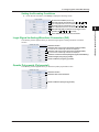
Basic Arithmetic (S1+S2, S1–S2, S1*S2, and S1/S2)
2
Math Source Waveforms (Source1 and Source2)
1
2
2
3
3
4
CH1 to CH16, 16chVOLT, 16chTEMP/VOLT, CAN, LIN, RMath1 to RMath15
1 You can select input channels of installed modules. However, you cannot select input channels
of a logic module.
2 When a 16-CH voltage input module or 16-CH temperature/voltage input module is installed.
After you select 16chVOLT or 16chTEMP/VOLT, select a sub channel.
3 On the DL850V when a CAN bus monitor module or CAN & LIN bus monitor module is installed.
After you select CAN or LIN, select a sub channel. You cannot select waveforms whose data
type (Value Type) is set to Logic. Even if the data type is not set to Logic, you cannot use data
that exceeds 16 bits in length.
4 You can use other RMath waveforms as math source waveforms. If you set the real time math
channel to RMathX, you can select the RMath waveforms on channels up to RMathX–1. If the
real time math channel is RMath1, you cannot use any other RMath waveforms as math source
waveforms.
Basic Arithmetic with Coefficients (A(S1)+B(S2)+C, A(S1)–B(S2)+C,
A(S1)*B(S2)+C, A(S1)/B(S2)+C)
Performs addition, subtraction, multiplication, or division with coefficients on the two waveforms
assigned to Source1 and Source2.
Math Source Waveforms (Source1 and Source2)
Coefficients (A, B, and C)
Set the scaling coefficients (A and B) and the offset (C).
Range: –9.9999E+30 to +9.9999E+30
Default value of A and B: 1.0000
Default value of C: 0.0000
Differentiation (Diff(S1))
Performs differentiation on the waveform assigned to Source using a fifth order Lagrange interpolation
formula. For details on the differentiation characteristics, see the appendix.
Math Source Waveform (Source)
The options are the same as were described above for basic arithmetic. For details, see “Notes
Regarding Using the Digital Filter and Real Time Math” on page 1-23.
IM DL850-51EN
3
4
5
App
Index
The options are the same as were described above for basic arithmetic. For details, see “Notes
Regarding Using the Digital Filter and Real Time Math” on page 1-23.
Features
Performs addition, subtraction, multiplication, or division on the two waveforms assigned to Source1
and Source2.
1-7
1 Features
Integration (Integ1(S1) and Integ2(S1))
Integration is performed on the waveform that has been assigned to Source.
• Integ1(S1): Performs integration on the positive component of the waveform assigned to Source
• Integ2(S1): Performs integration on the positive and negative components of the waveform
assigned to Source
Math Source Waveform (Source)
The options are the same as were described above for basic arithmetic. For details, see “Notes
Regarding Using the Digital Filter and Real Time Math” on page 1-23.
Reset Condition (Reset Condition)
Select the condition for resetting integration from one of the settings below.
• Start (Start): When the waveform acquisition starts
• Overlimit (Overlimit): When “Value/Div” exceeds +10 div or falls below –10 div
• Zero crossing (ZeroCross): When the math source waveform signal crosses zero
Set the slope direction (positive or negative) and the hysteresis when the signal crosses zero.
The hysteresis level is the same as the trigger hysteresis. For details, see the Features Guide,
IM DL850-01EN.
Manual Reset (Manual Reset)
To manually reset the integration, select Execute.
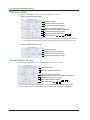
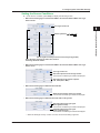
Angle of Rotation (Rotary Angle)
Uses the waveforms or logic signals that have been assigned to phases A, B, and Z to calculate the
angle of rotation. This can be used to calculate the angle of rotation or the displacement of an encoder.
Type (Type)
You can select the type of the encoding from the following options.
• Incremental ABZ (Incremental ABZ): The angle of rotation is calculated from the A, B, and Z
phase signals.
• Incremental AZ (Incremental AZ): The angle of rotation is calculated from the A and Z phase
signals.
• Absolute 8 bit (Absolute 8bit): The angle of rotation is calculated from an 8-bit logic signal (binary
code).
• Absolute 16 bit (Absolute 8bit): The angle of rotation is calculated from a 16-bit logic signal (binary
code).
• Gray code (Gray Code): The angle of rotation is calculated from a logic signal (gray code)
consisting of 2 to 16 bits.
Source Conditions (Source Condition)
Set the conditions of the source whose pulses you want to count.
If the type of the encoding is ABZ or AZ
• Turning the logic source on and off (Logic Source)
• ON: You can set the A, B, and Z phase signals to the signals of logic modules.
• OFF:You can set the A, B, and Z phase signals to the signals of analog waveform modules.
The options are the same as were described above for basic arithmetic. However, you cannot
select input channels of frequency modules or real time math channels (RMath). For details,
see “Notes Regarding Using the Digital Filter and Real Time Math” on page 1-23.
• When logic sources are turned on
• Source (Source):
Select an input channel of a logic module.
• Phase A (Phase A):Select the bit that you want to use for the phase A signal from among
the logic signals of the selected input channel.
• Phase B (Phase B):Select the bit that you want to use for the phase B signal from among
the logic signals of the selected input channel.
• Phase Z (Phase Z):Select the bit that you want to use for the phase Z signal from among
the logic signals of the selected input channel.
1-8
IM DL850-51EN
1 Features
• When logic sources are turned off
1 The options are the same as were described above for basic arithmetic. However, you cannot
select input channels of frequency modules or real time math channels (RMath). For details, see
“Notes Regarding Using the Digital Filter and Real Time Math” on page 1-23.
2 The signal level range is the same as the trigger level range. For details, see the Features
Guide, IM DL850-01EN.
3 The hysteresis level is the same as the trigger hysteresis. For details, see the features guide,
IM DL850-01EN.
If the type of the encoding is absolute 8 bit, absolute 16 bit, or gray code
Select the input channel of the logic module. For absolute 16 bit and gray code encoding, set the
logic channel for the least significant digits to Source1 and the logic channel for the most significant
digits to Source2.
* When the bit length of Gray Code is 8 or less, the Source2 setting is ignored.
1
Features
Set the input channels for the phase A, B, and Z signals,1 the signal level of each signal that you
will count as a pulse,2 and the hysteresis of each signal.3
• Phase A (Phase A): Set the input channel, signal level, and hysteresis of the phase A signal.
• Phase B (Phase B): Set the input channel, signal level, and hysteresis of the phase B signal.
• Phase Z (Phase Z): Set the input channel, signal level, and hysteresis of the phase Z signal.
To set the timing that pulses are counted and the timing that the pulse count is reset for the
signal level that you set here, see “Encoding Conditions” later in this section.
2
3
4
5
App
Pulses per Rotation (Pulse/Rotate)
Set the number of pulses per rotation.
Range: 1 to 65535. The default value is 180.
Index
Bit Length (Bit Length)
When the bit length (Bit Length) encoding type is set to Gray Code, set the bit length.
Selectable range: 2 to 16
Scaling (Scaling)
Select the unit that is used on the vertical scale.
• Radian:Radian
• Degree:Degrees
• User-defined (User Define): Set K, the size of the scale.
Range: –9.9999E+30 to +9.9999E+30. The default value is 1.0000.
Encoding Conditions (Encode Condition)
If the type of the encoding is ABZ or AZ, set the encoder’s pulse multiplier and the timing (edge) for
counting pulses.
Count Conditions (Count Condition)
You can select the encoder’s pulse multiplier from the following options.
×4, ×2, ×1
When the multiplier is ×4, regardless of the timing setting made in the next section, pulses are
counted on all the edges of the signal.
IM DL850-51EN
1-9
1 Features
Timing1 (Timing1)
Select the edges that are counted as pulses when the multiplier is ×1.
• A : Rising edge of the phase A signal
• A : Falling edge of the phase A signal
• B : Rising edge of the phase B signal
• B : Falling edge of the phase B signal
Rising edge: The point where the signal rises from a low level and passes through the specified
signal level
Falling edge: The point where the signal falls from a high level and passes through the specified
signal level
If the signal is that of an analog waveform, turn the logic sources off as shown earlier this manual in
“Source Conditions,” and then set the signal level that is counted as a pulse and the hysteresis.
Timing2 (Timing2)
Select the edges that are counted as pulses when the multiplier is ×2.
The options are the same as were described above for Timing1.
When the multiplier is ×2, if you select the same edges as in Timing1, the pulse count conditions
are the same as were explained for multiplier ×1.
Reset Timing (Reset Timing)
Select the timing (edge) at which the pulse count will be reset.
• A : Rising edge of the phase A signal
• A : Falling edge of the phase A signal
• B : Rising edge of the phase B signal
• B : Falling edge of the phase B signal
• Z level (Z Level): When the Z phase signal is at a high level.
Reverse (Reverse)
Set the direction that the angle of rotation increases in.
• ON: The rotation is counter-clockwise.
• OFF:The rotation is clockwise.
Manual Reset (Manual Reset)
To manually reset the angle of rotation, select Execute.
1-10
IM DL850-51EN
1 Features
1
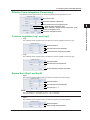
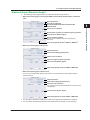
Logic Signal to Analog Waveform Conversion (DA)
Features
Converts the logic signals that have been assigned to Source1 (the least significant digits) and
Source2 (the most significant digits) into an analog waveform and scales the results.
2
Math Source Waveforms (Source1 and Source2)
You can select input channels of an installed logic module. Set the logic channel for the least
significant digits to Source1 and the logic channel for the most significant digits to Source2.
You cannot select the input channels of CAN bus monitor modules or CAN & LIN bus monitor
modules.
3
Type (Type)
4
Select the type of the logic signal.
• Unsigned:
Unsigned integer
• Signed:
Signed integer
• Offset Binary: Offset binary
5
Bit Length (Bit Length)
Set the bit length that will be converted to an analog signal. The length that you specify will be
counted from the least significant bit.
Range: 2 to 16. The default value is 16.
App
Coefficient (K)
Set scaling coefficient K.
Range: –9.9999E+30 to +9.9999E+30. The default value is 1.0000.
Index
Quartic Polynomial (Polynomial)
Performs a quartic polynomial calculation on the waveform that has been assigned to Source.
As4+Bs3+Cs2+Ds+E
A, B, C, and D: Scaling coefficients
s: Sampling data
E: Offset
Math Source Waveform (Source)
The options are the same as were described above for basic arithmetic. For details, see “Notes
Regarding Using the Digital Filter and Real Time Math” on page 1-23.
Coefficients (A, B, C, D, and E)
IM DL850-51EN
Set the scaling coefficients (A, B, C, and D) and the offset (E).
Range: –9.9999E+30 to +9.9999E+30
Default value of A and B: 1.0000
Default value of C, D, and E: 0.0000
1-11
1 Features
RMS Value (RMS)
Calculates the RMS value of the waveform that has been assigned to Source.
N
1
s(n)2
Nn=1
s: Sampling data
N:Number of samples
Math Source Waveform (Source)
The options are the same as were described above for basic arithmetic. However, you cannot select
an input channel of a frequency module. For details, see “Notes Regarding Using the Digital Filter
and Real Time Math” on page 1-23.
Calculation Period (Calc Period)
Select the method that is used to determine the RMS calculation period.
• Edge: Rising or falling edge of the selected signal or both edges
• Time: Specified time
If the Calculation Period Is Edge
• Edge detection source (Edge Source)
Select the input channel of the signal that is used to determine the calculation period.
If you want to use the same channel as the math source waveform, select Own. You can also
select other channels. For details, see “Notes Regarding Using the Digital Filter and Real Time
Math” on page 1-23.
• Level (Level), Slope (Slope), and Hysteresis (Hysteresis)
Set the signal level,1 the slope (rising or falling), and the hysteresis2 of the edges that separate
the calculation periods.
1 The signal level range is the same as the trigger level range. For details, see the Features
Guide , IM DL850-01EN.
2 The hysteresis level is the same as the trigger hysteresis. For details, see the Features Guide ,
IM DL850-01EN.
If the Calculation Period Is Time
Time (Time)
Set the calculation period time.
Range: 1 ms to 500 ms. Default value: 1 ms. Resolution: 1 ms.
Effective Power (Power)
Calculates the effective power of the waveforms that have been assigned to Source1 and Source2.
1
T
T
(s1 • s2)dt
0
T: 1 period (calculation period)
s1 and s2: Sampling data
dt: Sampling period
Math Source Waveforms (Source1 and Source2)
Set the voltage and current input channels to use to calculate the effective power to Source1 and
Source2. The options are the same as were described above for basic arithmetic. However, you
cannot select input channels of a frequency module. For details, see “Notes Regarding Using the
Digital Filter and Real Time Math” on page 1-23.
Calculation Period (Calc Period)
Set the calculation period for the effective power calculation.
1-12
IM DL850-51EN
1 Features
Edge Detection Source (Edge Source)
1
Features
Select the input channel of the signal that is used to determine the calculation period.
If you want to use the same channel as the math source waveform, select Source1 or Source2. You
can also select other channels. For details, see “Notes Regarding Using the Digital Filter and Real
Time Math” on page 1-23.
2
Level (Level), Slope (Slope), and Hysteresis (Hysteresis)
Set the signal level, the slope, and the hysteresis of the edges that separate the calculation periods.
These settings are shared with the RMS operation.
Effective Power Integration (Power Integ)
Integrates the effective power of the waveforms that have been assigned to Source1 and Source2.
T
4
(s1 • s2)dt
0
5
T: Integration time
s1 and s2: Sampling data
dt: Sampling period
Math Source Waveforms (Source1 and Source2)
Set the voltage and current input channels to use to integrate the effective power to Source1 and
Source2. The options are the same as were described above for basic arithmetic. However, you
cannot select input channels of a frequency module. For details, see “Notes Regarding Using the
Digital Filter and Real Time Math” on page 1-23.
Reset Condition (Reset Condition)
Select the condition for resetting integration from one of the settings below.
• Start (Start):
When the waveform acquisition starts
• Overlimit (Overlimit): When “Value/Div” exceeds +10 div or falls below –10 div
Manual Reset (Manual Reset)
To manually reset the integration, select Execute.
Scaling (Scaling)
Select the unit that is used on the vertical scale.
• Seconds (Second): The unit is seconds.
• Hours (Hour):
The unit is hours.
Common Logarithm (Log1 and Log2)
• Log1:Calculates the common logarithm of the waveforms that have been assigned to Source1 and
Source2 (the calculation is performed on “Source1/Source2”).
K • log10(s1/s2)
K: Coefficient.
s1 and s2: Sampling data.
• Log2:Calculates the common logarithm of the waveform that has been assigned to Source.
K • log10(s)
K: Coefficient.
s: Sampling data.
Math Source Waveforms (Source1, Source2, and Source)
The options are the same as were described above for basic arithmetic. For details, see “Notes
Regarding Using the Digital Filter and Real Time Math” on page 1-23.
Coefficient (K)
Set scaling coefficient K.
Range: –9.9999E+30 to +9.9999E+30. The default value is 1.0000.
IM DL850-51EN
3
1-13
App
Index
1 Features
Square Root (Sqrt1 and Sqrt2)
• Sqrt1: Calculates the square root of the sum (or difference) of the squares of the waveforms
that have been assigned to Source1 and Source2. This can be used to analyze displacement and
tolerance.
s12 ± s22 s1 and s2: Sampling data
• Sqrt2: Calculates the square root of the waveform that has been assigned to Source
s s: Sampling data
Math Source Waveforms (Source1, Source2, and Source)
The options are the same as were described above for basic arithmetic. For details, see “Notes
Regarding Using the Digital Filter and Real Time Math” on page 1-23.
Sign (Sign)
Set the operator between s12 and s22 in Sqrt1.
• +: Addition
• –: Subtraction
Cosine (Cos) and Sine (Sin)
Uses the waveforms or logic signals that have been assigned to phases A, B, and Z to determine the
angle, and then calculates the cosine or sine of this angle. You can use this to convert the angle to
displacement.
Type (Type)
Select the type of the encoding. The settings other than the Resolver Ch setting are shared with the
Rotary Angle operation. You can specify the Resolver Ch setting when there is a channel that has
been defined with the resolver function of real time math.
• If there are multiple channels that have been defined with the resolver function, select Resolver
Ch, and then select the channel.
• If Resolver Ch has been selected, the setup menu explained later is not displayed.
Source Conditions (Source Condition)
Set the conditions of the source whose pulses you want to count. This setting is shared with the
Rotary Angle operation. For details, see “Notes Regarding Using the Digital Filter and Real Time
Math” on page 1-23.
Pulses per Rotation (Pulse/Rotate) and Bit Length (Bit Length)
Set the number of pulses per rotation. When the encoding type is set to Gray Code, set the bit
length. This setting is shared with the Rotary Angle operation.
Encoding Conditions (Encode Condition)
If the type of the encoding is ABZ or AZ, set the encoder’s pulse multiplier and the timing (edge) for
counting pulses. This setting is shared with the Rotary Angle operation.
Manual Reset (Manual Reset)
To manually reset the computed value, select Execute.
1-14
IM DL850-51EN
1 Features
Arc Tangent (Atan)
1
Features
Calculates the arc tangent of the waveforms that have been assigned to Source1 and Source2 (the
calculation is performed on “Source1/Source2”). You can use this to convert the displacement to an
angle.
atan(s1/s2)
s1 and s2: Sampling data
2
Math Source Waveforms (Source1 and Source2)
The options are the same as were described above for basic arithmetic. For details, see “Notes
Regarding Using the Digital Filter and Real Time Math” on page 1-23.
3
Scaling (Scaling)
Select the unit that is used on the vertical scale. This setting is shared with the Rotary Angle
operation. However, there are no user-defined settings.
4
Quadrant Range (Quadrant)
Select the quadrant range to use for converting displacements to angles. This can be used on
models with firmware version 2.05 and later.
• Quadrant-2: –90° to +90° (–π/2 to +π/2)
Even if a calculated result is between –180° and –90° or between +90° and +180°, it is converted
to an angle between –90° to +90°.
• Quadrant-4: –180° to +180° (–π to +π)
Electrical Angle (Electrical Angle)
Calculates the phase difference between (1) the angle that was determined from the logic signals that
were specified for phases A, B, and Z, and (2) the fundamental component that was determined from
the discrete Fourier transform of the waveform that was specified as the target. You can calculate the
phase difference (electrical angle) between the motor’s angle of rotation and the motor drive current.
Type (Type)
Select the type of the encoding. The settings other than the Resolver Ch setting are shared with the
Rotary Angle operation. You can specify the Resolver Ch setting when there is a channel that has
been defined with the resolver function of real time math.
• If there are multiple channels that have been defined with the resolver function, select Resolver
Ch, and then select the channel.
• If Resolver Ch has been selected, set the scaling and the target on the setup menus explained
later.
Source Conditions (Source Condition)
Set the conditions of the source whose pulses you want to count. This setting is shared with the
Rotary Angle operation. However, you can only specify the input channels of logic modules as math
source waveforms. For details, see “Notes Regarding Using the Digital Filter and Real Time Math”
on page 1-23.
Pulses per Rotation (Pulse/Rotate) and Bit Length (Bit Length)
Set the number of pulses per rotation. When the encoding type is set to Gray Code, set the bit
length. This setting is shared with the Rotary Angle operation.
Scaling (Scaling)
Select the unit that is used on the vertical scale. This setting is shared with the Rotary Angle
operation. However, there are no user-defined settings.
Encoding Conditions (Encode Condition)
If the type of the encoding is ABZ or AZ, set the encoder’s pulse multiplier and the timing (edge) for
counting pulses. This setting is shared with the Rotary Angle operation.
Target (Target)
The fundamental component of the waveform that you specify here is determined through a discrete
Fourier transform. If the angle is the motor’s angle of rotation and the target is the motor’s drive
current, the electrical angle can be determined.
The options are the same as were described above for basic arithmetic. However, you cannot select
an input channel of a frequency module. For details, see “Notes Regarding Using the Digital Filter
and Real Time Math” on page 1-23.
IM DL850-51EN
1-15
5
App
Index
1 Features
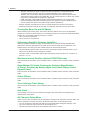
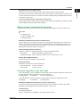
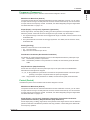
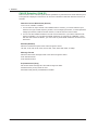
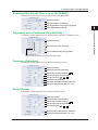
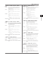
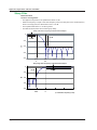
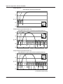
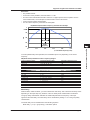
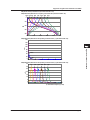
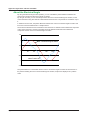
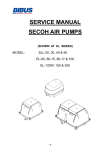
Knocking Filter (Knock Filter; only on the DL850V)
When the signal level of the waveform that has been set to Source is less than or equal to the
elimination level, the signal of this waveform is set to 0. You can select whether to perform
differentiation. You can use this to extract knocking.
Knocking
Engine cylinder pressure
Elimination level
(noise elimination level)
Differentiation
turned on
Valve opening/closing noise
Valve opening/closing noise
is eliminated.
Only the knocking part is extracted.
Used as a trigger
Math Source Waveform (Source)
The options are the same as were described above for basic arithmetic. However, you cannot select
an input channel of a frequency module or a real time math channel (RMath). For details, see “Notes
Regarding Using the Digital Filter and Real Time Math” on page 1-23.
Elimination Level
Set the elimination level, which is used to set the input signal to 0.
The range of the elimination level is the same as that of the trigger level. For details, see the
Features Guide, IM DL850-01EN.
Differential
Select whether to differentiate the waveform after elimination. A fifth order Lagrange interpolation
formula is used to perform differentiation. For details on the differentiation characteristics, see the
appendix.
• ON: Differentiation is performed.
• OFF:Differentiation is not performed.
Polynomial with a coefficient (Poly-Add-Sub)
Performs addition or subtraction or both on the waveforms that have been set to Source1, Source2,
Source3, and Source4. You can add or subtract the result of the power calculation, to calculate the
multi-phase power.
K ( ±s1 ±s2 ±s3 ±s4)
K: Coefficient.
s1, s2, s3, and s4: Sampling data.
Math Source Waveforms (Source1, Source2, Source3, and Source4)
The options are the same as were described above for basic arithmetic. For details, see “Notes
Regarding Using the Digital Filter and Real Time Math” on page 1-23.
Sign
You can set the sign of the sampling data of the math source waveforms to positive or negative.
Coefficient (K)
Set scaling coefficient K.
Range: –9.9999E+30 to +9.9999E+30. The default value is 1.0000.
1-16
IM DL850-51EN
1 Features
1
Frequency (Frequency)
Math Source Waveform (Source)
The options are the same as were described above for basic arithmetic. However, you can select
an input channel of a logic module (select the channel, and then select the bit). You cannot select
an input channel of a frequency module. For details, see “Notes Regarding Using the Digital Filter
and Real Time Math” on page 1-23.
Features
Calculates the frequency of the waveform that has been assigned to Source.
2
3
Slope (Slope), Level (Level), Hysteresis (Hysteresis)
Set the signal level,1 the slope (rising or falling), and the hysteresis2 of the edges that are used to
detect the periods. If the math source is the signal of a logic module, only set the slope.
1 The signal level range is the same as the trigger level range. For details, see the Features Guide,
IM DL850-01EN.
2 The hysteresis level is the same as the trigger hysteresis. For details, see the Features Guide,
IM DL850-01EN.
Scaling (Scaling)
5
App
Select the unit that is used on the vertical scale.
• Hz: The unit is hertz.
• Rpm:The unit is revolutions per minute.
Index
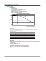
Deceleration Prediction (Deceleration Prediction)
Set whether to compute the decelaration curve from the elapsed time after the pulse input stops.
• ON: Deceleration prediction is performed.
• OFF:Deceleration prediction is not performed. For details, see the features guide, IM DL85001EN.
Stop Prediction (Stop Prediction)
Set the time from the point when the pulse input stops to the point when the DL850/DL850V
determines that the object has stopped.
• 2, 4, 8, 16: S
top prediction is performed on the basis of the specified number of times the pulse
period (T) of the pulse one period before the pulse input stopped.
• OFF: Stop prediction is not performed. For details, see the features guide, IM DL850-01EN.
Period (Period)
Calculates the period of the waveform that has been assigned to Source.
Math Source Waveform (Source)
The options are the same as were described above for basic arithmetic. However, you can select
an input channel of a logic module (select the channel, and then select the bit). You cannot select
an input channel of a frequency module. For details, see “Notes Regarding Using the Digital Filter
and Real Time Math” on page 1-23.
Slope (Slope), Level (Level), Hysteresis (Hysteresis), Deceleration Prediction
(Deceleration Prediction), Stop Prediction (Stop Prediction)
Set the slope (rising or falling), signal level, and hysteresis of the edges that are used to detect the
periods as well as the deceleration prediction and stop prediction. These settings are shared with
the Frequency operation.
IM DL850-51EN
4
1-17
1 Features
Edge Count (Edge Count)
Counts the number of slope edges of the waveform that has been assigned to Source. You can use
this to count the number of events in consecutive tests.
Math Source Waveform (Source)
The options are the same as were described above for basic arithmetic. However, you can select
an input channel of a logic module (select the channel, and then select the bit). You cannot select
an input channel of a frequency module. For details, see “Notes Regarding Using the Digital Filter
and Real Time Math” on page 1-23.
Slope (Slope), Level (Level), Hysteresis (Hysteresis)
Set the slope (rising or falling), the signal level, and the hysteresis of the edges that you want to
count. These settings are shared with the Frequency operation.
Reset Condition (Reset Condition)
Select the condition for resetting the count from one of the settings below.
• Start (Start):
When the waveform acquisition starts
• Overlimit (Overlimit): When “Value/Div” exceeds +10 div or falls below –10 div
Manual Reset (Manual Reset)
To manually reset the count, select Execute.
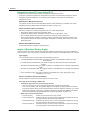
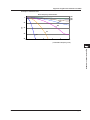
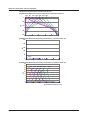
Resolver (Resolver)
Calculates the angle of rotation from the sine signal and cosine signal that are generated from the
detection coils of the resolver depending on the angle of the rotor. This function can be used on
models with firmware version 2.00 and later.
Sine Phase Signal and Cosine Phase Signal (Sin Ch, Cos Ch)
Select the sine signal and the cosine signal that are generated from the detection coil of the
resolver. The options are the same as were described above for basic arithmetic. For details, see
“Notes Regarding Using the Digital Filter and Real Time Math” on page 1-23.
Hysteresis (Hysteresis)
Set the rising edge hysteresis of the excitation, sine, and cosine signals. When the sample point
mode (which is explained below) is set to Auto, this setting is applied to all signals. When the
sample point mode is set to Manual, this setting is applied to the excitation signal.
Sample Point (Sample Point)
Excitation Signal (Carrier Ch)
Select the resolver’s excitation signal. The options are the same as were described above for basic
arithmetic. For details, see “Notes Regarding Using the Digital Filter and Real Time Math” on page
1-23.
1-18
IM DL850-51EN
1 Features
Mode (Mode)
2
3
4
5
Tracking Filter (Tracking Filter)
If the sine signal and cosine signal data is changing in a staircase pattern, select the cutoff
frequency of the tracking filter that will smooth out the data that is used to calculate the angle of
rotation.
OFF, 2kHz, 1kHz, 250Hz, 100Hz
App
Scaling (Scaling)
Index
Select how the upper and lower limits of the vertical scale are displayed.
–180Deg to +180Deg, 0Deg to 360Deg, –PI to +PI, 0 to 2PI
* “PI” is displayed as “π” on the screen.
Note
• To improve the calculation accuracy, set the vertical axis sensitivity for each signal so that the signal
amplitude is as large as possible.
• Set the vertical axis sensitivity to the same value for sine signals and cosine signals. If you specify
different values, the DL850/DL850V cannot perform calculations correctly.
IIR Filter (IIR Filter)
This can be used to filter the waveform that has been set to Source with the same characteristics of
the IIR filter of the digital filter. You can set the frequency to values over a wider range than is available
with the IIR filter of the digital filter. This function can be used on models with firmware version 2.00
and later.
Math Source Waveforms (Source)
The options are the same as were described above for basic arithmetic. For details, see “Notes
Regarding Using the Digital Filter and Real Time Math” on page 1-23.
Filter Band (Filter Band)
Select the filter band.
Low-Pass, High-Pass, Band-Pass
IM DL850-51EN
1
Features
To enable more accurate calculations of the angle of rotation, set the mode that is used to sample
the peak values of sine and cosine signals.
• Auto: The rising edges of the excitation, sine, and cosine signals are detected, and the peak
values of sine signals and cosine signals are sampled automatically.
• The Auto setting can be applied when the time difference of the sine and cosine signals in
reference to the excitation signal is less than ±90°(π/2).
• Turn the SCALE knob to set the vertical scale (V/div) so that the amplitudes of the excitation,
sine, and cosine signals are all ±1.5 div or greater. If the amplitudes are less than ±1.5 div, the
Auto function will not operate.
• Manual: The rising edge of the excitation signal is detected, and sine and cosine signals at the
specified time (Time) after this detected rising edge are sampled.
Time Setting
Selectable range: 0.1 μs to 1000.0 μs, Default value: 0.1 μs, Resolution: 0.1 μs.
1-19
1 Features
Cutoff Frequency (CutOff)
When the filter band is set to Low-Pass or High-Pass, set the cutoff frequency. The ranges and
resolutions are indicated below.
Filter Band
Low-Pass
Range
0.2 Hz to 3.00 MHz
Default value: 0.30 MHz
High-Pass
0.02 kHz to 3.00 MHz
Default value: 0.30 MHz
Resolution
0.2 Hz (range: 0.2 Hz to 29.8 Hz)
2 Hz (range: 30 Hz to 298 Hz)
0.02 kHz (range: 0.30 kHz to 2.98 kHz)
0.2 kHz (range: 3.0 kHz to 29.8 kHz)
2 kHz (range: 30 kHz to 298 kHz)
0.02 MHz (range: 0.30 MHz to 3.00 MHz)
0.02 kHz (range: 0.02 kHz to 2.98 kHz)
0.2 kHz (range: 3.0 kHz to 29.8 kHz)
2 kHz (range: 30 kHz to 298 kHz)
0.02 MHz (range: 0.30 MHz to 3.00 MHz)
Center Frequency (Center Frequency)
When the filter band is set to Band-Pass, set the center frequency. The ranges and resolutions are
indicated below.
Range
0.06 kHz to 3.00 MHz
Default value: 0.30kHz
Resolution
0.02 kHz (range: 0.06 kHz to 1.18 kHz)
0.2 kHz (range: 1.2 kHz to 11.8 kHz)
2 kHz (range: 12 kHz to 118 kHz)
0.02 MHz (range: 0.12 MHz to 3.00 MHz)
Bandwidth (Pass Band)
When the filter band is set to Band-Pass, select the bandwidth. The bandwidth options vary
depending on the center frequency that you have set. For details on the options, see the appendix.
Interpolation On and Off (Interpolate)
Select whether to perform data interpolation. Up to 10 M samples of data can be interpolated from
the data of waveforms that pass through the real time math IIR filter. The interpolation method is
linear interpolation.
• ON: Data is interpolated.
• OFF: Data is not interpolated.
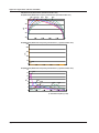
Demodulation of the Pulse Width Modulated Signal (PWM)
Integrates a pulse width modulation signal and demodulates it to an analog signal. This function can
be used on models with firmware version 2.00 and later.
Math Source Waveforms (Source)
The options are the same as were described above for basic arithmetic. For details, see “Notes
Regarding Using the Digital Filter and Real Time Math” on page 1-23.
Period of the Pulse Width Modulated Signal (Period)
Set the period of the pulse width modulated signal. The pulse width modulation signal is repeatedly
integrated over the set period and demodulated to an analog signal.
Selectable range: 0.1 μs to 5000.0 μs, Default value: 0.1 μs, Resolution: 0.1 μs.
1-20
IM DL850-51EN
1 Features
1
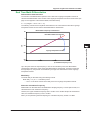
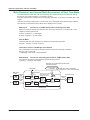
Reactive Power (Reactive Power(Q))
Apparent Power Calculation
1. Calculate the RMS voltage and current (RMS) that are used to derive the reactive power.
2. Take the product of the RMS voltage and current (S1*S2) that were calculated in step 1. The
result is the apparent power.
Features
Calculates the reactive power from apparent power and effective power.
To calculate the reactive power, you must use the real time math feature to calculate the apparent
power and effective power by following the procedure below. This function can be used on models with
firmware version 2.05 and later.
2
3
4
Effective Power Calculation
Calculate the effective power of the RMS voltage and current (Power) that are used to derive the
reactive power.
5
Apparent Power (Apparent Power(S))
Select the real time math channel (RMath channel) used to calculate the apparent power.
App
Effective Power (Effective Power(P))
Select the real time math channel (RMath channel) used to calculate the effective power.
Reactive Power Polarity
Determine the reactive power polarity from the phases of the voltage and current used to derive the
reactive power.
Voltage (Voltage)
Select the voltage channel used to derive the reactive power.
The options are the same as were described above for basic arithmetic. However, you cannot
select input channels of frequency modules. For details, see “Notes Regarding Using the Digital
Filter and Real Time Math” on page 1-23.
Hysteresis (Hysteresis)
Select the hysteresis used to detect the zero crossing of the selected voltage.
The hysteresis level is the same as the trigger hysteresis. For details, see the Features Guide ,
IM DL850-01EN.
Current (Current)
Select the current channel used to derive the reactive power.
The options are the same as were described above for basic arithmetic. However, you cannot
select input channels of frequency modules. For details, see “Notes Regarding Using the Digital
Filter and Real Time Math” on page 1-23.
IM DL850-51EN
1-21
Index
1 Features
CAN ID Detection (CAN ID)
Detect the frame of the CAN bus signal with the specified ID. A pulse waveform whose detection point
is at high level is displayed. This function can be used on DL850V models with firmware version 2.05
and later.
Detection Source Waveforms (Source)
CH1 to CH16,1 RMath1 to RMath2
1 You can select an input channel of an installed module. However, you cannot select the input
channels of a logic module, frequency module, 16-CH voltage input module, 16-CH temperature/
voltage input module, CAN bus monitor module, or CAN & LIN bus monitor module.
2 You can use other RMath waveforms as math source waveforms. If you set the real time math
channel to RMathX, you can select the RMath waveforms on channels up to RMathX–1. If the
real time math channel is RMath1, you cannot use any other RMath waveforms as math source
waveforms.
Bit Rate (Bit Rate)
Select the transmission speed of the CAN bus signal to detect.
10k, 20k, 33.3k, 50k, 62.5k, 66.7k, 83.3k, 100k, 125k, 250k, 500k, 800k, or 1Mbps
Message Format
Select the data frame message format of the CAN bus signal to detect.
STD: Standard format
XTD: Extended format
ID (Hexadecimal (Hex))
Set the data frame message ID of the CAN bus signal to detect.
Standard format (11 bits): 0x000 to 0x7ff
Extended format (29 bits): 0x00000000 to 0x1fffffff
1-22
IM DL850-51EN
1 Features
1
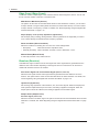
Notes Regarding Using the Digital Filter and Real Time Math
Features
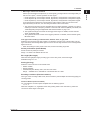
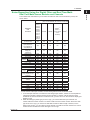
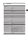
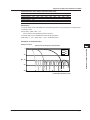
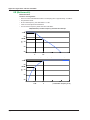
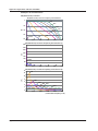
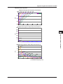
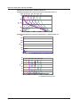
Real Time Math Source Modules and Channels
The modules and channels that you can select as real time math source waveforms (source) are
shown below.
Operators
and
Functions
S1+S2, S1–S2,
S1*S2, S1/S2
A(S1)+B(S2)+C,
A(S1)–B(S2)+C,
A(S1)*B(S2)+C,
A(S1)/B(S2)+C
Diff(S1),
Integ1(S1),
Integ2(S1)
Rotary Angle
DA
Polynomial
RMS, Math source
Power Edge source
Power Integ
Log1, Log2
Sqrt1, Sqrt2
Cos, Sin
Atan
Electrical Math source
Angle
Target
Knock Filter
(Only settable on the
DL850V)
Poly-Add-Sub
Frequency,
Period
Edge Count
Resolver
IIR Filter
PWM
Reactive Power(Q)
CAN ID
2
Input Module Model and RMath (Real Time Math Channel)
(Yes: Can be selected, No: Cannot be selected)
701250,
701251,
701255,
701260,
7202401, 2
701261,
7202411, 2
701262,
701280
720230
(Only usable
RMath3
701265,
on the
701270,
DL850V)
701271,
701275,
720210,
7202211
Yes
Yes
No
Yes
Yes
Yes
Yes
No
Yes
Yes
Yes
Yes
No
Yes
Yes
Yes4
No
Yes
Yes
Yes
Yes
Yes
Yes
Yes4
Yes
No
Yes
No
No
Yes
No
No
No
Yes
Yes
No
Yes
No
No
Yes4
Yes
No
No
Yes
No
No
No
Yes4
No
Yes
No
Yes
No
Yes
Yes
Yes*2
Yes
Yes
Yes
Yes
Yes
No
Yes
No
No
Yes
Yes
Yes
Yes
Yes
Yes
No
Yes
No
Yes
Yes
No
No
Yes
No
Yes
Yes
No
Yes
Yes
Yes
No
Yes
Yes
Yes
Yes
No
No
No
No
No
2
Yes
Yes
Yes
Yes
Yes
Yes
Yes
Yes
Yes
Yes
Yes
Yes5
No
Yes
Yes
Yes
No
No
Yes
Yes
Yes
Yes
Yes2
No
3
4
5
App
Index
For the names of the input modules, see the Getting Started Guide, IM DL850-03EN.
1 To set the input channels of a 720220 16-CH voltage input module, 720221 16-CH temperature/
voltage input module, 720240 CAN bus monitor module, or 720241 CAN & LIN bus monitor
module as the source waveforms of real time math, you have to turn on the waveform display (set
Display to ON).
2 When the data type (Value Type) is set to Logic, you cannot select the input channels of a
720240 CAN bus monitor module or a 720241 CAN & LIN bus monitor module. Even if the data
type is not set to Logic, you cannot use data that exceeds 16 bits in length. However, for the
Edge Count function, you can select an input channel of a CAN bus monitor module or a CAN &
LIN bus monitor module even if the data type is set to Logic.
IM DL850-51EN
1-23
1 Features
3 If you set the real time math channel to RMathX, you can select the RMath waveforms on
channels up to RMathX–1. If the real time math channel is RMath1, you cannot use any other
RMath waveforms as math source waveforms.
4 If you have turned logic sources on, select an input channel of a 720230 logic module. If logic
sources have been turned off, select an input channel of an analog waveform module.
5 The input channels of a 16-CH voltage input module (720220) or 16-CH temperature/voltage
input module (720221) cannot be selected.
Math Delay
The real time math delay is “1.4 μs + the digital filter delay + the math delay.”
The digital filter and math delays vary depending on the type of filter and math operation.
• If you are using the result of a real time math channel as the source waveform for another real time
math operation, the math delays accumulate.
• For details, see the appendix.
Internal Processing of Real Time Math
The math source waveforms are 16-bit binary data. If they are only 12 bits long, they are converted to
16 bits. Internally, the waveforms are converted to floating-point numbers and calculated.
• The math results are converted to 16-bit data in relation to the range (value/div) and are then
recorded in acquisition memory.
• The basic display is 2400 LSB/div (the same as the 16-bit analog waveform module).
• For details on the internal math expressions, see the appendix.
1-24
IM DL850-51EN
1 Features
1
Differences between Real Time Math and Standard Math
Features
This section explains the differences between the real time math operations that you configure by
pressing CH (/G3 option) and the standard math operations that you configure by pressing MATH.
2
Real Time Math
• Math operations can be performed in real time on waveforms (A/D converted data) that are
applied to the input channels of each of the modules.
• Even when the display is in roll mode, you can view the real time math results.
• There are no limits on the record length. Because the data of normal input channels is switched
with the real time math results and acquired in acquisition memory, you can specify the same
record length as that of the normal input channels.
• You can trigger the DL850/DL850V on real time math results.
• Regardless of the DL850/DL850V sample rate, math operations are always performed on the
data that is output from each module at a maximum math rate of 10 MS/s.
• Real time math can be used in all acquisition modes (including the dual capture mode).
16 channels
Plug-in
module
Engine 2
App
Trigger circuit
ACQ memory
Index
Standard Math
• Because waveforms are processed after they are acquired, the waveform update period is long.
• Math cannot be performed when the display is in roll mode.
• Math is performed on data that was acquired into acquisition memory at the DL850/DL850V
sample rate.
• Because math results are stored in the main memory of the main CPU, there are limits on the
record length (for one channel, the maximum is 1 Mpoint).
• You can not trigger the DL850/DL850V on math results.
• Because math is performed by a general-purpose CPU, a wide variety of expressions are
available.
16 channels
GIGAZoom
Engine 2
ACQ memory
IM DL850-51EN
5
GIGAZoom
16 channels
Real time math
4
16 channels
Real time math
Math operations
Plug-in
module
3
Main CPU
Math results
1-25
2
Configuring Digital Filter Settings
1
2
Digital Filter
Gauss
Configuring Digital Filter Settings
The digital filter operation menu has the following settings:
• Filter type: You can select from four filter types—Gauss, Sharp, IIR, and Mean.
• Filter band:You can select the type of filter bands.
• Delay: You can add a delay to the updating of data after data passes through a digital filter.
For details on the digital filter, see chapter 1.
For the filter characteristics, see the appendix.
3
4
This section explains the following settings (which are used when using the Gauss filter):
• Filter type
• Interpolation
• Filter band
• Delay
• Cutoff frequency
5
CH Menu
App
1. Press a key from CH1 to CH16, and then the RealTime Math soft key to select OFF.
2. Press the Filter/Delay Setup soft key and then the Bandwidth soft key to select Digital.
The following menu appears.
Index
When you have selected the input
channel of a frequency module
Select Digital.
Select ON.
Select Gauss.
Set the filter band (Low-Pass).
Set the cutoff frequency (using the jog shuttle).
Turns interpolation on and off
Set the delay (using the jog shuttle).
Note
• The same delay is used for all filter types of the same channel.
• To display the Filter/Delay Setup soft key on the setup menu that is displayed when you press a key from
CH1 to CH16, press the RealTime Math soft key to select OFF.
• If you want to perform real time math at the same time as the digital filter, press the RealTime Math soft
key again to select ON.
• For information on other features, how to use these features, and handling precautions, see the following
manuals.
• The Features Guide, IM DL850-01EN
• The User’s Manual, IM DL850-02EN
• The Getting Started Guide, IM DL850-03EN
IM DL850-51EN
2-1
2 Configuring Digital Filter Settings
Sharp
This section explains the following settings (which are used when using the Sharp filter):
• Filter type
• Filter band
• Cutoff frequency
• Center frequency
• Bandwidth
• Interpolation
• Delay
CH Menu
1. Press a key from CH1 to CH16, and then the RealTime Math soft key to select OFF.
2. Press the Filter/Delay Setup soft key and then the Bandwidth soft key to select Digital.
The following menu appears.
When you have selected the input
channel of a frequency module
Select Digital.
Select ON.
Select Sharp.
When Filter Band Is Set
to Band-Pass
Set the filter band
(Low-Pass, High-Pass, Band-Pass).
Set the cutoff frequency
(using the jog shuttle).
Set the center frequency
(using the jog shuttle).
Set the bandwidth
(using the jog shuttle).
Turns interpolation on and off
Set the delay
(using the jog shuttle).
Note
• The same delay is used for all filter types of the same channel.
• To display the Filter/Delay Setup soft key on the setup menu that is displayed when you press a key from
CH1 to CH16, press the RealTime Math soft key to select OFF.
• If you want to perform real time math at the same time as the digital filter, press the RealTime Math soft
key again to select ON.
• For information on other features, how to use these features, and handling precautions, see the following
manuals.
• The Features Guide, IM DL850-01EN
• The User’s Manual, IM DL850-02EN
• The Getting Started Guide, IM DL850-03EN
2-2
IM DL850-51EN
2 Configuring Digital Filter Settings
IIR
1
This section explains the following settings (which are used when using the IIR filter):
• Filter type
• Filter band
• Cutoff frequency
• Center frequency
• Bandwidth
• Interpolation
• Delay
2
Configuring Digital Filter Settings
3
CH Menu
4
1. Press a key from CH1 to CH16, and then the RealTime Math soft key to select OFF.
2. Press the Filter/Delay Setup soft key and then the Bandwidth soft key to select Digital.
The following menu appears.
5
When you have selected the input
channel of a frequency module
Select Digital.
Select ON.
Select IIR.
App
When Filter Band Is Set
to Band-Pass
Index
Set the filter band
(Low-Pass, High-Pass, Band-Pass).
Set the cutoff frequency
(using the jog shuttle).
Set the center frequency
(using the jog shuttle).
Set the bandwidth
(using the jog shuttle).
Turns interpolation on and off
Set the delay
(using the jog shuttle).
Note
• The same delay is used for all filter types of the same channel.
• To display the Filter/Delay Setup soft key on the setup menu that is displayed when you press a key from
CH1 to CH16, press the RealTime Math soft key to select OFF.
• If you want to perform real time math at the same time as the digital filter, press the RealTime Math soft
key again to select ON.
• For information on other features, how to use these features, and handling precautions, see the following
manuals.
• The Features Guide, IM DL850-01EN
• The User’s Manual, IM DL850-02EN
• The Getting Started Guide, IM DL850-03EN
IM DL850-51EN
2-3
2 Configuring Digital Filter Settings
Mean
This section explains the following settings (which are used when using the Mean filter):
• Filter type
• Number of taps
• Mean sample
• Interpolation
• Delay
CH Menu
1. Press a key from CH1 to CH16, and then the RealTime Math soft key to select OFF.
2. Press the Filter/Delay Setup soft key and then the Bandwidth soft key to select Digital.
The following menu appears.
When you have selected the input
channel of a frequency module
Select Digital.
Select ON.
Select Mean.
Set the number of taps (using the jog shuttle).
Set the mean sample (using the jog shuttle).
Turns interpolation on and off
Set the delay (using the jog shuttle).
Note
• The same delay is used for all filter types of the same channel.
• To display the Filter/Delay Setup soft key on the setup menu that is displayed when you press a key from
CH1 to CH16, press the RealTime Math soft key to select OFF.
• If you want to perform real time math at the same time as the digital filter, press the RealTime Math soft
key again to select ON.
• For information on other features, how to use these features, and handling precautions, see the following
manuals.
• The Features Guide, IM DL850-01EN
• The User’s Manual, IM DL850-02EN
• The Getting Started Guide, IM DL850-03EN
2-4
IM DL850-51EN
3
Configuring Real Time Math Settings
1
2
Real Time Math Settings
This section explains the following settings (which are used when performing real time math):
• Real time math on/off
• Real time math settings
• Input settings for all channels
3
1. Press a key from CH1 to CH16, and then the RealTime Math soft key to select ON to display
the following menu.
Configuring Real Time Math Settings
RMath Menu
4
5
Turn real time math on.
App
Configure real time math settings.
Index
Turns the mean on and off
Optimizes value/div
Note
• When you turn real time math on, the colors that are used to display the menu title are inverted.
When OFF
Is Selected
When ON
Is Selected
The colors are inverted.
• For information on other features, how to use these features, and handling precautions, see the following
manuals.
• The Features Guide, IM DL850-01EN
• The User’s Manual, IM DL850-02EN
• The Getting Started Guide, IM DL850-03EN
IM DL850-51EN
3-1
3 Configuring Real Time Math Settings
Configuring Real Time Math Settings (RealTime Math Setup)
2. Press the RealTime Math Setup soft key to display the following screen.
Example when the Operation is S1+S2
Select an operator or function (see the operations
and function that are described later in this section).
Select the math source waveforms
(CH1 to CH16,1 RMath1 to RMath152).
1 You can select channels in which input modules that support basic arithmetic are installed.
2 You can select channels whose numbers are smaller than the channel you are operating.
Operations and Functions
Menu Item
S1+S2
S1−S2
S1*S2
S1/S2
A(S1)+B(S2)+C
A(S1)−B(S2)+C
A(S1)*B(S2)+C
A(S1)/B(S2)+C
Diff(S1)
Integ1(S1)
Integ2(S1)
Rotary Angle
DA
Polynomial
RMS
Power
Power Integ
Log1
Log2
Sqrt1
Sqrt2
Cos
Sin
Atan
Electrical Angle
Knock Filter
Poly-Add-Sub
Frequency
Period
Edge Count
Resolver
IIR Filter
PWM
Reactive Power(Q)
CAN ID
Description
Basic arithmetic
Basic arithmetic with
coefficients
Differentiation
Integration
Addition
Subtraction
Multiplication
Division
Addition
Subtraction
Multiplication
Division
Area of the positive amplitude (T-Y waveform)
Area of the positive amplitude minus area of the negative
amplitude (T-Y waveform)
Angle of rotation
Logic signal to analog waveform conversion
Quartic polynomial
RMS value
Effective power
Effective power integration
Common logarithm
Common logarithm of S1/S2
Common logarithm of S1
Square root
Square root of “S12 ± S22”
Square root of S1
Cosine
Sine
Arc tangent
Electrical angle
Knocking filter (only on the DL850V)
Polynomial with a coefficient
Frequency
Period
Edge count
Resolver
IIR Filter
Demodulation of the Pulse Width Modulated Signal
Reactive power
CAN ID detection
Note
For details on the types of modules that support the operations and functions, see “Notes Regarding Using
the Digital Filter and Real Time Math,” in chapter 1.
3-2
IM DL850-51EN
3 Configuring Real Time Math Settings
1
ALL CH Menu
1. Press ALL CH to display the following menu.
2
3
Configuring Real Time Math Settings
Configure real time math settings.
4
5
App
Note
• For information on other features, how to use these features, and handling precautions, see the following
manuals.
• The Features Guide, IM DL850-01EN
• The User’s Manual, IM DL850-02EN
• The Getting Started Guide, IM DL850-03EN
Configuring Real Time Math Settings for All Channels (RealTime Math)
2. Press the RealTime Math soft key to display the following screen.
The displayed contents vary depending
on the real time math operation that has been
specified for the channel at the cursor position.
Use the jog shuttle to move the cursor
to the item that you want to set.
IM DL850-51EN
3-3
Index
3 Configuring Real Time Math Settings
Basic Arithmetic (S1+S2, S1−S2, S1*S2, and S1/S2)
The following screen appears when you select a basic arithmetic operation.
Select the operation.
Select the math source waveforms.
Basic Arithmetic with Coefficients (A(S1)+B(S2)+C, A(S1)−B(S2)+C,
A(S1)*B(S2)+C, and A(S1)/B(S2)+C)
The following screen appears when you select a basic arithmetic operation with coefficients.
Select the operation.
Select the math source waveforms.
Set the coefficients (using the jog shuttle).
Differentiation (Diff(S1))
The following screen appears when you select the differentiation function.
Select the function.
Select the math source waveform.
Integration (Integ1(S1) and Integ2(S2))
The following screen appears when you select an integration function.
Select the function.
Select the math source waveform.
Reset conditions for the integration result
• When waveform acquisition starts
• When “Value/Div” exceeds +10 div or falls below –10 div
• When the math source waveform
crosses zero and an edge is generated
Resets the integration result
3-4
IM DL850-51EN
3 Configuring Real Time Math Settings
1
Angle of Rotation (Rotary Angle)
1. The following screen appears when you select the angle-of-rotation function.
• When the Encoding Type Is Incremental ABZ, Incremental AZ, Absolute 8bit, or Absolute
16bit
2
Select the function.
Select the encoding type
(Incremental ABZ, Incremental AZ, Absolute 8bit,
Absolute 16bit).
3
Set the number of pulses per rotation
(using the jog shuttle).
4
Select the scale (Radian, Degree, User Define).
Set the size of the scale (only when Scaling is set to User Define)
(using the jog shuttle).
Set the encoding conditions.
You can set the conditions when the encoding type
is ABZ or AZ.
Resets the math result
5
App
• When the Encoding Type Is Gray Cord
Index
Select the function.
Select the encoding type (Gray Cord).
Set the source conditions.
Set the bit length (using the jog shuttle).
Select the scale (Radian, Degree, User Define).
Set the size of the scale (only when Scaling is set to User Define)
(using the jog shuttle).
IM DL850-51EN
Configuring Real Time Math Settings
Set the source conditions.
3-5
3 Configuring Real Time Math Settings
Setting the Source Conditions
2. Under Source Condition, press Setup to display the following screen.
• When the Encoding Type Is Incremental ABZ or Incremental AZ and When the Logic
Source Is Off
Turn logic sources off.
Set the hysteresis (
,
,
).
Set the signal level that you want to count (using the jog shuttle).
Select the signal channels for phases A, B, and Z of
the analog waveform module.
• When the Encoding Type Is Incremental ABZ or Incremental AZ and When the Logic
Source Is On
Turn logic sources on.
Select the input channel of the logic module.
The channels of installed logic modules are displayed.
Select the bits of logic signals of
phases A, B, and Z (Bit1 to Bit8).
• When the Encoding Type Is Absolute 8bit
Select the input channel of the logic module.
The channels of installed logic modules are displayed.
• When the Encoding Type Is Absolute 16bit or Gray Code
Select the math source logic signal
(least significant 8 bits).
The channels of installed logic modules are displayed.
Select the math source logic signal
(most significant 8 bits).
The channels of installed logic modules are displayed.
* When the bit length of Gray Code is 8 or less, the Source2 setting is ignored.
3-6
IM DL850-51EN
3 Configuring Real Time Math Settings
1
Setting the Encoding Conditions
3. Under Encode Condition, press Setup to display the following screen.
2
Set the count condition (x4, x2, x1).
Select the edge to count pulses on (A , A , B , B ).
This is displayed when Count Condition is set to x2 or x1.
Select the edge to count pulses on (A , A , B , B
This is displayed when Count Condition is set to x2.
).
3
Turns rotation direction inversion on and off
4
Logic Signal to Analog Waveform Conversion (DA)
The following screen appears when you select the logic signal to analog waveform conversion
function.
5
Select the function.
Select the math source logic signal (least significant 8 bits).
The channels of installed logic modules are displayed.
Select the math source logic signal (most significant 8 bits).
The channels of installed logic modules are displayed.
App
Select the conversion method (Unsigned, Signed, Offset Binary).
Set the bit length (using the jog shuttle).
Index
Set the coefficient (using the jog shuttle).
Quartic Polynomial (Polynomial)
The following screen appears when you select the quartic polynomial function.
Select the function.
Select the math source waveform.
Set the coefficients (using the jog shuttle).
IM DL850-51EN
Configuring Real Time Math Settings
Select the edge that you want to use to trigger a reset
operation (A , A , B , B , Z Level).
3-7
3 Configuring Real Time Math Settings
RMS Value (RMS)
The following screen appears when you select the RMS value function.
• If the Calculation Period Is Edge
Select the function.
Select the math source waveform.
Set the calculation period to Edge.
Select the edge detection source
(Own, CH1 to CH161, RMath1 to RMath152).
Set the level (using the jog shuttle).
Set the edge detection condition (
Set the hysteresis (
,
,
,
,
).
).
1 You can select channels in which input modules that support basic arithmetic are installed.
2 You can select channels whose numbers are smaller than the channel you are operating.
• If the Calculation Period Is Time
Select the function.
Select the math source waveform.
Set the calculation period to Time.
Set the time (using the jog shuttle).
Effective Power (Power)
The following screen appears when you select the effective power function.
Select the function.
Select the math source waveforms.
Select the edge detection source
(Source1, Source2, CH1 to CH161, RMath1 to RMath152).
Set the level (using the jog shuttle).
Set the edge detection condition (
Set the hysteresis (
,
,
,
,
).
).
1 You can select channels in which input modules that support basic arithmetic are installed.
2 You can select channels whose numbers are smaller than the channel you are operating.
3-8
IM DL850-51EN
3 Configuring Real Time Math Settings
1
Effective Power Integration (Power Integ)
The following screen appears when you select the effective power integration function.
2
Select the function.
Select the math source waveforms.
Reset conditions for the integration result
• When waveform acquisition starts
• When “Value/Div” exceeds +10 div or falls below –10 div
3
Configuring Real Time Math Settings
Resets the integration result
4
Select the scale (Second, Hour).
Common Logarithm (Log1 and Log2)
• Log1
5
The following screen appears when you select the common logarithm function (Log1).
Select the function.
App
Select the math source waveforms.
Set the coefficient (using the jog shuttle).
Index
• Log2
The following screen appears when you select the common logarithm function (Log2).
Select the function.
Select the math source waveform.
Set the coefficient (using the jog shuttle).
Square Root (Sqrt1 and Sqrt2)
• Sqrt1
The following screen appears when you select the square root function (Sqrt1).
Select the function.
Select the math source waveforms.
Select the sign (+, –).
Note
When you set Sign to +, the square root of “S12 + S22” is calculated.
When you set Sign to –, the square root of “S12 – S22” is calculated.
• Sqrt2
The following screen appears when you select the square root function (Sqrt2).
Select the function.
Select the math source waveform.
IM DL850-51EN
3-9
3 Configuring Real Time Math Settings
Cosine (Cos) and Sine (Sin)
1. The following screen appears when you select the cosine or sine function.
• When the Encoding Type Is Incremental ABZ, Incremental AZ, Absolute 8bit, or Absolute
16bit
Select the function.
Select the encoding type
(Incremental ABZ, Incremental AZ, Absolute 8bit,
Absolute 16bit).
Set the source conditions.
Set the number of pulses per rotation
(using the jog shuttle).
Set the encoding conditions.*
Resets the math result *
* You can set the conditions when the encoding type is ABZ or AZ.
• When the Encoding Type Is Gray Code
Select the function.
Select the encoding type (Gray Cord).
Set the source conditions.
Set the bit length (using the jog shuttle).
• When the Encoding Type Is Resolver Ch
You can only configure the settings when there is a channel that has been defined with the
resolver function.
Select the function.
Select the encoding type (Resolver Ch).
Select the resolver channel*
The channels that have been defined with the resolver
function are displayed.
* You can select channels whose numbers are smaller than the channel you are operating.
3-10
IM DL850-51EN
3 Configuring Real Time Math Settings
1
Setting the Source Conditions
2. Under Source Condition, press Setup to display the following screen.
• When the Encoding Type Is Incremental ABZ or Incremental AZ and When the Logic
Source Is Off
2
Turn logic sources off.
3
,
,
Configuring Real Time Math Settings
Set the hysteresis (
).
4
5
App
Set the signal level that you want to count (using the jog shuttle).
Index
Select the signal channels for phases A, B, and Z of
the analog waveform module.
• When the Encoding Type Is Incremental ABZ or Incremental AZ and When the Logic
Source Is On
Turn logic sources on.
Select the input channel of the logic module.
The channels of installed logic modules are displayed.
Select the bits of logic signals of phases
A, B, and Z (Bit1 to Bit8).
• When the Encoding Type Is Absolute Encode 8bit
Select the input channel of the logic module.
The channels of installed logic modules are displayed.
• When the Encoding Type Is Absolute Encode 16bit or Gray Code
Select the math source logic signal
(least significant 8 bits).
The channels of installed logic modules are displayed.
Select the math source logic signal
(most significant 8 bits).
The channels of installed logic modules are displayed.
* When the bit length of Gray Code is 8 or less, the Source2 setting is ignored.
IM DL850-51EN
3-11
3 Configuring Real Time Math Settings
Setting the Encoding Conditions
3. Under Encode Condition, press Setup to display the following screen.
Set the count condition (x4, x2, x1).
Select the edge to count pulses on (A , A , B , B ).
This is displayed when Count Condition is set to x2 or x1.
Select the edge to count pulses on (A , A , B , B
This is displayed when Count Condition is set to x2.
).
Select the edge that you want to use to trigger a reset
operation (A , A , B , B , Z Level).
Turns rotation direction inversion on and off
Arc Tangent (Atan)
The following screen appears when you select the arc tangent function.
Select the function.
Select the math source waveforms.
Select the scale (Radian, Degree).
Select the quadrant range (Quadrant-2, Quadrant-4).
3-12
IM DL850-51EN
3 Configuring Real Time Math Settings
1
Electrical Angle (Electrical Angle)
1. The following screen appears when you select the electrical angle function.
• When the Encoding Type Is Incremental ABZ, Incremental AZ, Absolute 8bit, or Absolute
16bit
2
Select the function.
Select the encoding type
(Incremental ABZ, Incremental AZ, Absolute 8bit,
Absolute 16bit).
3
Set the number of pulses per rotation (using the jog shuttle).
Select the scale (Radian, Degree).
Set the encoding conditions.
You can set the conditions when the encoding type is
ABZ or AZ.
App
• When the Encoding Type Is Gray Code
Select the function.
Index
Select the encoding type (Gray Cord).
Set the source conditions.
Set the bit length (using the jog shuttle).
Select the scale (Radian, Degree).
Select the target (CH1 to CH161, RMath1 to RMath152).
• When the Encoding Type Is Resolver Ch
You can only configure the settings when there is a channel that has been defined with the
resolver function.
Select the function.
Select the encoding type (Resolver Ch).
Select the resolver channel2
The channels that have been defined with the resolver function
are displayed.
Select the scale (Radian, Degree).
Select the target (CH1 to CH161, RMath1 to RMath152).
1 You can select channels in which input modules that support basic arithmetic are installed.
2 You can select channels whose numbers are smaller than the channel you are operating.
IM DL850-51EN
4
5
Select the target (CH1 to CH161, RMath1 to RMath152).
Configuring Real Time Math Settings
Set the source conditions.
3-13
3 Configuring Real Time Math Settings
Setting the Source Conditions
2. Under Source Condition, press Setup to display the following screen.
• When the Encoding Type is Incremental ABZ or Incremental AZ
Select the input channel of the logic module.
The channels of installed logic modules are displayed.
Select the bits of logic signals of phases
A, B, and Z (Bit1 to Bit8).
Note
You cannot use analog waveforms as sources.
• When the Encoding Type Is Absolute 8bit
Select the input channel of the logic module.
The channels of installed logic modules are displayed.
• When the Encoding Type Is Absolute 16bit or Gray Code
Select the math source logic signal
(least significant 8 bits).
The channels of installed logic modules are displayed.
Select the math source logic signal
(most significant 8 bits).
The channels of installed logic modules are displayed.
* When the bit length of Gray Code is 8 or less, the Source2 setting is ignored.
Setting the Encoding Conditions
3. Under Encode Condition, press Setup to display the following screen.
Set the count condition (x4, x2, x1).
Select the edge to count pulses on (A , A , B , B ).
This is displayed when Count Condition is set to x2 or x1.
Select the edge to count pulses on (A , A , B , B
This is displayed when Count Condition is set to x2.
).
Select the edge that you want to use to trigger a reset
operation (A , A , B , B , Z Level).
Turns rotation direction inversion on and off
3-14
IM DL850-51EN
3 Configuring Real Time Math Settings
1
Knocking Filter (Knock Filter; only on the DL850V)
The following screen appears when you select the knocking filter function.
2
Select the function.
Select the math source waveform.
Set the elimination level (using the jog shuttle).
3
Turns differentiation on and off
Configuring Real Time Math Settings
Polynomial with a Coefficient (Poly-Add-Sub)
4
The following screen appears when you select the polynomial with a coefficient function.
Select the function.
5
Select the math source waveforms.
App
Set the coefficient (using the jog shuttle).
Select the sign (+, –).
Press SET to switch between the positive and negative signs.
Index
Frequency (Frequency)
The following screen appears when you select the frequency function.
Select the function.
Select the math source waveform.
Set the edge detection condition (
,
).
Set the level (using the jog shuttle).
Set the hysteresis (
,
,
).
Select the scale (Hz, Rpm).
Select the deceleration prediction (OFF, ON).
Select the stop prediction (OFF, 2, 4, 8, 16).
Period (Period)
The following screen appears when you select the period function.
Select the function.
Select the math source waveform.
Set the edge detection condition (
,
).
Set the level (using the jog shuttle).
Set the hysteresis (
,
,
).
Select the deceleration prediction (OFF, ON).
Select the stop prediction (OFF, 2, 4, 8, 16).
IM DL850-51EN
3-15
3 Configuring Real Time Math Settings
Edge Count (Edge Count)
The following screen appears when you select the edge count function.
Select the function.
Select the math source waveform.
Set the edge detection condition (
,
).
Set the level (using the jog shuttle).
Set the hysteresis (
,
,
).
Edge count result reset conditions
• When the edge count operation begins
• When “Value/Div” exceeds +10 div or falls below –10 div
Resets the edge count result
Resolver (Resolver)
The following screen appears when you select the resolver function.
Select the function.
Select the sine phase signal (CH1 to CH161, RMath1 to RMath152).
Select the cosine phase signal (CH1 to CH161, RMath1 to RMath152).
Set the hysteresis (
,
,
).
Configure the sample point.
• Select the excitation signal (CH1 to CH161, RMath1 to RMath152).
• Set the Mode (Auto, Manual).
• Set the move time of the sample point (only when Mode is set to Manual)
(using the jog shuttle).
Select the tracking filter (OFF, 2kHz, 1kHz, 250Hz, 100Hz).
Select the scale
(–180Deg − +180Deg, 0Deg − 360Deg, –PI − +PI, 0 − 2PI).
* “PI” is displayed as “π” on the screen.
1 You can select channels in which input modules that support basic arithmetic are installed.
2 You can select channels whose numbers are smaller than the channel you are operating.
3-16
IM DL850-51EN
3 Configuring Real Time Math Settings
1
IIR Filter (IIR Filter)
The following screen appears when you select the IIR filter function.
• When Filter Band Is Set to Low-Pass or High-Pass
2
Select the function.
Select the math source waveform.
3
Set the filter band (Low-pass, High-Pass).
Set the cutoff frequency (using the jog shuttle).
Configuring Real Time Math Settings
4
Turns interpolation on and off.
• When Filter Band Is Set to Band-Pass
5
Select the function.
Select the math source waveform.
Set the filter band (Band-pass).
App
Set the center frequency (using the jog shuttle).
Set the bandwidth (using the jog shuttle).
Turns interpolation on and off.
Index
Demodulation of the Pulse Width Modulated Signal (PWM)
When you select the function that is used to demodulate pulse width modulated signals, the following
screen appears.
Select the function.
Select the math source waveform.
Set the period (using the jog shuttle).
IM DL850-51EN
3-17
3 Configuring Real Time Math Settings
Reactive Power (Reactive Power(Q))
The following screen appears when you select the reactive power (Q) function.
Select the function.
Select the real time math channel (RMath channel)
used to calculate the apparent power.
Select the real time math channel (RMath channel)
used to calculate the effective power.
Select the voltage channel used to derive the reactive power.
Set the hysteresis for the selected voltage. (
,
,
)
Select the current channel used to derive the reactive power.
CAN ID Detection (CAN ID)
The following screen appears when you select the CAN ID function.
Select the function.
Select the detection source waveform.
Select the bit rate
(10k, 20k, 33.3k, 50k, 62.5k, 66.7k, 83.3k, 100k, 125k, 250k,
500k, 800k, 1Mbps).
Select the message format (STD, XTD).
Set the message ID.
3-18
IM DL850-51EN
4
Commands
Command
RMATh CHANnel Group
:CHANnel<x1>:RMATh:ATANgent:
SCALe
:CHANnel<x>:RMATh:ATANgent:
QUADrant
:CHANnel<x>:RMATh:AVALue
1
Function
Page
Sets or queries the scale of the specified channel’s arc tangent operation.
4-5
IM DL850-51EN
4-5
3
4-5
4-5
4
4-5
4-5
Commands
Sets or queries the quadrant range for the arctangent calculation of the
specified channel.
Sets or queries coefficient A of the currently specified real time math
operation.
:CHANnel<x>:RMATh:BVALue
Sets or queries coefficient B of the currently specified real time math
operation.
:CHANnel<x>:RMATh:BWIDth:BAND
Sets or queries the band of the specified channel’s digital filter.
:CHANnel<x>:RMATh:BWIDth:
Sets or queries the center frequency of the bandpass filter of the specified
CFRequency
channel’s digital filter.
:CHANnel<x>:RMATh:BWIDth:CUToff Sets or queries the cutoff frequency of the specified channel’s digital filter.
:CHANnel<x>:RMATh:BWIDth:
Sets or queries the interpolation function of the specified channel’s digital
INTerpo
filter.
:CHANnel<x>:RMATh:BWIDth:MEAN? Queries all mean settings of the specified channel’s digital filter.
:CHANnel<x>:RMATh:BWIDth:MEAN: Sets or queries the sample of the mean of the specified channel’s digital filter.
SAMPle (Base Sample)
:CHANnel<x>:RMATh:BWIDth:MEAN: Sets or queries the taps of the mean of the specified channel’s digital filter.
TAP
:CHANnel<x>:RMATh:BWIDth:MODE
Sets or queries the filter mode of the specified channel.
:CHANnel<x>:RMATh:BWIDth:PBANd Sets or queries the bandwidth of the bandpass filter of the specified channel’
(Pass Band)
s digital filter.
:CHANnel<x>:RMATh:BWIDth:TYPE
Sets or queries the digital filter type of the specified channel.
:CHANnel<x>:RMATh:CANId:BRATe
Sets or queries the CAN ID bit rate of the specified channel.
(Bit Rate)
:CHANnel<x>:RMATh:CANId:MFORmat Sets or queries the CAN ID message format of the specified channel.
(Message Format)
:CHANnel<x>:RMATh:CANId:MID
Sets or queries the CAN ID message ID of the specified channel.
(Message ID)
:CHANnel<x>:RMATh:CANId:SOURce Sets or queries the CAN ID detection source waveform of the specified
channel.
:CHANnel<x>:RMATh:CVALue
Sets or queries coefficient C of the currently specified real time math
operation.
:CHANnel<x>:RMATh:DA?
Queries all logic signal to analog waveform conversion settings.
:CHANnel<x>:RMATh:DA:BLENgth
Sets or queries the logic signal to analog waveform conversion bit length.
(Bit Length)
:CHANnel<x1>:RMATh:DA:
Sets or queries the math source waveform that you want to convert into an
SOURce<x2>
analog waveform.
:CHANnel<x>:RMATh:DA:TYPE
Sets or queries the logic signal to analog waveform conversion method (type).
:CHANnel<x>:RMATh:DELay
Sets or queries the delay of the specified channel.
:CHANnel<x>:RMATh:DVALue
Sets or queries coefficient D of the currently specified real time math
operation.
:CHANnel<x>:RMATh:ECOunt? (Edge Queries all reset condition settings for the specified channel’s edge count
Count)
operation.
:CHANnel<x>:RMATh:ECOunt:
Resets the counter of the specified channel’s edge count operation.
MRESet:EXECute (Manual Reset)
:CHANnel<x>:RMATh:ECOunt:
Sets or queries whether the edge count is reset when an over limit occurs for
OVERange
the specified channel’s edge count operation.
:CHANnel<x>:RMATh:ECOunt:SRESet Sets or queries whether the edge count is reset when the edge count
(Start Reset)
operation starts for the specified channel.
:CHANnel<x>:RMATh:EVALue
Sets or queries coefficient E of the currently specified real time math
operation.
:CHANnel<x>:RMATh:FREQ?
Queries all the settings for the specified channel’s frequency, period, and
edge count (excluding reset) operations.
:CHANnel<x>:RMATh:FREQ:BIT
Sets or queries the math source waveform (the source bit) for the specified
channel’s frequency, period, and edge count operations (when the source is
a logic channel).
:CHANnel<x>:RMATh:FREQ:
Sets or queries whether frequency and period computation’s deceleration
DECeleration
prediction is turned on.
2
4-6
4-6
5
4-6
4-6
App
4-7
4-7
4-7
Index
4-7
4-8
4-8
4-8
4-8
4-8
4-8
4-8
4-8
4-9
4-9
4-9
4-9
4-9
4-9
4-9
4-9
4-10
4-10
4-10
4-1
List of Commands
Command
:CHANnel<x>:RMATh:FREQ:
HYSTeresis
:CHANnel<x>:RMATh:FREQ:LEVel
Function
Sets or queries the detection hysteresis for the specified channel’s frequency,
period, and edge count operations.
Sets or queries the detection level for the specified channel’s frequency,
period, and edge count operations.
:CHANnel<x>:RMATh:FREQ:SCALe
Sets or queries the scale of the specified channel’s frequency operation.
:CHANnel<x>:RMATh:FREQ:SLOPe
Sets or queries the detection slope for the specified channel’s frequency,
period, and edge count operations.
:CHANnel<x>:RMATh:FREQ:SOURce
Sets or queries the math source waveform for the specified channel’s
frequency, period, and edge count operations.
:CHANnel<x>:RMATh:FREQ:
Sets or queries whether frequency and period computation’s stop prediction
STOPpredict
is turned on.
:CHANnel<x1>:RMATh:IFILter?
Queries all IIR filter operation settings.
:CHANnel<x1>:RMATh:IFILter:BAND Sets or queries the band of the IIR filter operation.
:CHANnel<x1>:RMATh:IFILter:
Sets or queries the cutoff frequency of the IIR filter operation.
CUToff
:CHANnel<x1>:RMATh:IFILter:
Sets or queries the center frequency of the bandpass filter of the IIR filter
CFRequency
operation.
:CHANnel<x1>:RMATh:IFILter:
Sets or queries the bandwidth of the bandpass filter of the IIR filter operation.
PBANd
:CHANnel<x1>:RMATh:IFILter:
Sets or queries whether interpolation is used with the IIR filter operation.
INTerpo
:CHANnel<x>:RMATh:INTegral?
Queries all integration settings of the specified channel.
:CHANnel<x>:RMATh:INTegral:
Resets the integrated value of the specified channel.
MRESet:EXECute (Manual Reset)
:CHANnel<x>:RMATh:INTegral:
Sets or queries whether the integrated value is reset when an over limit
OVERange
occurs for the specified channel.
:CHANnel<x>:RMATh:INTegral:
Sets or queries whether the integrated value is reset when integration starts
SRESet (Start Reset)
for the specified channel.
:CHANnel<x>:RMATh:INTegral:
Queries all settings related to the integrated value being reset when the
ZRESet?
signal crosses zero in integration of the specified channel.
:CHANnel<x>:RMATh:INTegral:
Sets or queries the hysteresis that is used for resetting the integrated value
ZRESet:HYSTeresis
when the signal crosses zero for the specified channel.
:CHANnel<x>:RMATh:INTegral:
Sets or queries whether the integrated value is reset when the signal crosses
ZRESet:MODE
zero for the specified channel.
:CHANnel<x>:RMATh:INTegral:
Sets or queries the slope that is used for resetting the integrated value when
ZRESet:SLOPe
the signal crosses zero for the specified channel.
:CHANnel<x>:RMATh:KNOCkflt?
Queries all knocking filter settings of the specified channel.
:CHANnel<x>:RMATh:KNOCkflt:
Sets or queries the differentiation on/off status of the specified channel’s
DIFFerential
knocking filter.
:CHANnel<x>:RMATh:KNOCkflt:
Sets or queries the elimination level of the specified channel’s knocking filter.
ELEVel
:CHANnel<x>:RMATh:LABel
Sets or queries the label of the specified RMath channel (the specified
channel when real time math is turned on).
:CHANnel<x>:RMATh:MAVG (Moving Sets or queries the on/off status of the mean of the specified RMath channel
Average)
(the specified channel when real time math is turned on).
:CHANnel<x>:RMATh:MODE
Sets or queries the real time math on/off status of the specified channel.
:CHANnel<x>:RMATh:OFFSet
Sets or queries the offset of the specified RMath channel (the specified
channel when real time math is turned on).
:CHANnel<x>:RMATh:OPERation
Sets or queries the operation of the specified real time math channel.
:CHANnel<x>:RMATh:OPTimize
Optimizes the vertical scale of the specified channel that will be used in real
time math.
:CHANnel<x>:RMATh:PASub:SIGN
Sets or queries the signs of the sources for the polynomial with a coefficient
operation of the specified channel.
:CHANnel<x>:RMATh:PINTegral?
Queries all effective power integration settings of the specified channel.
:CHANnel<x>:RMATh:PINTegral:
Resets the effective power integration of the specified channel.
MRESet:EXECute
:CHANnel<x>:RMATh:PINTegral:
Sets or queries whether the integrated power value of the specified channel
OVERange
is reset when an over limit occurs during effective power integration.
:CHANnel<x>:RMATh:PINTegral:
Sets the reference time for the effective power integration of the specified
SCALe
channel.
:CHANnel<x>:RMATh:PINTegral:
Sets or queries whether the integrated value is reset when the effective
SRESet
power integration starts for the specified channel.
:CHANnel<x>:RMATh:POSition
Sets or queries the vertical position of the specified RMath channel (the
specified channel when real time math is turned on).
4-2
Page
4-10
4-10
4-10
4-10
4-11
4-11
4-11
4-11
4-11
4-11
4-12
4-12
4-12
4-12
4-12
4-12
4-12
4-12
4-13
4-13
4-13
4-13
4-13
4-13
4-13
4-14
4-14
4-14
4-14
4-14
4-14
4-14
4-14
4-15
4-15
4-15
IM DL850-51EN
List of Commands
Command
:CHANnel<x>:RMATh:POWer?
Function
IM DL850-51EN
Page
4-15
1
4-15
4-15
4-15
4-16
2
3
4-16
4-16
4-16
4-16
4-16
4-17
4-17
4-17
4-17
4-17
4-17
4-18
4-18
4-18
4-18
4-18
4-18
4-19
4-19
4-19
4-19
4-19
4-19
4-20
4-3
4
Commands
Queries all effective power calculation period settings of the specified
channel.
:CHANnel<x>:RMATh:POWer:TERM:
Sets or queries the effective power calculation period’s edge detection math
EBIT
source waveform of the specified channel (when a logic channel is being
used as the edge detection channel).
:CHANnel<x>:RMATh:POWer:TERM:
Sets or queries the effective power calculation period’s detection hysteresis
EHYSteresis
of the specified channel.
:CHANnel<x>:RMATh:POWer:TERM:
Sets or queries the effective power calculation period’s detection level of the
ELEVel
specified channel.
:CHANnel<x>:RMATh:POWer:TERM:
Sets or queries the effective power calculation period’s detection slope of the
ESLope
specified channel.
:CHANnel<x>:RMATh:POWer:TERM:
Sets or queries the effective power calculation period’s edge detection math
ESOurce
source waveform of the specified channel.
:CHANnel<x1>:RMATh:PWM:PERiod
Sets or queries the period of the PWM operation.
:CHANnel<x>:RMATh:RANGle?
Queries all settings related to the angle-of-rotation, electrical angle, sine, and
cosine operations of the specified channel.
:CHANnel<x>:RMATh:RANGle:
Sets or queries the bit length when the encoding type is GRAY for the
BLENgth
specified channel’s angle-of-rotation, electrical angle, sine, and cosine
operations.
:CHANnel<x>:RMATh:RANGle:
Sets or queries the resolution for the specified channel’s angle-of-rotation,
CCONdition
electrical angle, sine, and cosine operations.
:CHANnel<x>:RMATh:RANGle:ETYPe Sets or queries the encoding type for the specified channel’s angle-of(Edge Type)
rotation, electrical angle, sine, and cosine operations.
:CHANnel<x1>:RMATh:RANGle:
Sets or queries the slope for the specified math source waveform for the
HYSTeresis<x2>
specified channel’s angle-of-rotation, electrical angle, sine, and cosine
operations.
:CHANnel<x1>:RMATh:RANGle:
Sets or queries the detection level for the specified math source waveform
LEVel<x2>
for the specified channel’s angle-of-rotation, electrical angle, sine, and cosine
operations.
:CHANnel<x>:RMATh:RANGle:LOGic? Queries all the math source waveform settings for the specified channel’s
angle-of-rotation, electrical angle, sine, and cosine operations.
:CHANnel<x>:RMATh:RANGle:LOGic: Sets or queries the math source waveform mode for the specified channel’s
MODE
angle-of-rotation, electrical angle, sine, and cosine operations.
:CHANnel<x1>:RMATh:RANGle:
Sets or queries the source bit when the math source waveform mode for
LOGic:SBIT<x2> (Source BIT)
the specified channel’s angle-of-rotation, electrical angle, sine, and cosine
operations is logic.
:CHANnel<x1>:RMATh:RANGle:
Sets or queries the math source waveform when the math source waveform
LOGic:SOURce<x2>
mode for the specified channel’s angle-of-rotation, electrical angle, sine, and
cosine operations is logic.
:CHANnel<x1>:RMATh:RANGle:
Resets the angle of the specified channel’s angle operations.
MRESet:EXECute
:CHANnel<x>:RMATh:RANGle:PROTate Sets or queries the number of pulses per rotation for the specified channel’s
(Pulse per Rotate)
angle-of-rotation, electrical angle, sine, and cosine operations.
:CHANnel<x>:RMATh:RANGle:
Sets or queries whether the rotation direction is inverted for the specified
REVerse
channel’s angle-of-rotation, electrical angle, sine, and cosine operations.
:CHANnel<x1>:RMATh:RANGle:
Sets or queries the math source waveform when the encoding type of the
RSOurce (Resolver Source Ch)
angle-of-rotation, sine, and cosine operations is RESolver.
:CHANnel<x>:RMATh:RANGle:RTIMing Sets or queries the timing that will be used to reset the number of rotations
(Reset Timing)
for the specified channel’s angle-of-rotation, electrical angle, sine, and cosine
operations.
:CHANnel<x1>:RMATh:RANGle:SCALe Sets or queries the scale of the specified channel’s angle-of-rotation and
electrical angle operations.
:CHANnel<x>:RMATh:RANGle:SLOGic Sets or queries the math source waveform type for the specified channel’s
(Source Logic)
angle-of-rotation, electrical angle, sine, and cosine operations.
:CHANnel<x1>:RMATh:RANGle:
Sets or queries the math source waveform when the math source waveform
SOURce<x2>
mode for the specified channel’s angle-of-rotation, electrical angle, sine, and
cosine operations is not logic.
:CHANnel<x1>:RMATh:RANGle:
Sets or queries the edge detection timing for the specified channel’s angleTIMing<x2> (Edge Timing)
of-rotation, electrical angle, sine, and cosine operations.
:CHANnel<x1>:RMATh:RESolver?
Queries all resolver operation settings.
:CHANnel<x1>:RMATh:RESolver:
Sets or queries the math source waveform of the resolver operation.
SOURce<x2>
:CHANnel<x1>:RMATh:RESolver:
Sets or queries the sample mode of the resolver operation.
SMODe(Sample Mode)
5
App
Index
List of Commands
Command
:CHANnel<x1>:RMATh:RESolver:
HYSTeresis
:CHANnel<x1>:RMATh:RESolver:
STIMe(Sampling Time)
:CHANnel<x1>:RMATh:RESolver:
TFILter
:CHANnel<x1>:RMATh:RESolver:
SCALe
:CHANnel<x>:RMATh:RMS?
:CHANnel<x>:RMATh:RMS:TERM:EBIT
Function
4-20
Sets or queries the scale of the resolver operation.
4-20
Queries all RMS calculation period settings of the specified channel.
Sets or queries the edge detection math source waveform (the detection bit)
for when the RMS calculation period of the specified channel is set to edge
(when a logic channel is being used as the edge detection channel).
:CHANnel<x>:RMATh:RMS:TERM:
Sets or queries the detection hysteresis for when the RMS calculation period
EHYSteresis
of the specified channel is set to edge.
:CHANnel<x>:RMATh:RMS:TERM:
Sets or queries the detection level for when the RMS calculation period of
ELEVel
the specified channel is set to edge.
:CHANnel<x>:RMATh:RMS:TERM:
Sets or queries the detection slope for when the RMS calculation period of
ESLope
the specified channel is set to edge.
:CHANnel<x>:RMATh:RMS:TERM:
Sets or queries the edge detection math source waveform for when the RMS
ESOurce
calculation period of the specified channel is set to edge.
:CHANnel<x>:RMATh:RMS:TERM:MODE Sets or queries the RMS calculation period mode of the specified channel.
:CHANnel<x>:RMATh:RMS:TERM:TIME Sets or queries the interval for when the RMS calculation period of the
specified channel is set to time.
:CHANnel<x>:RMATh:RPOWer:
Sets or queries the apparent-power, effective-power, voltage, or current
SOURce<x2>
channel used to calculate the reactive power of the specified channel.
:CHANnel<x>:RMATh:RPOWer:
Sets or queries the hysteresis of the voltage channel used to calculate the
VOLTage:HYSTeresis
reactive power of the specified channel.
:CHANnel<x1>:RMATh:SC<x2>
Sets or queries source waveforms 1 to 3 of the currently specified real time
math operation.
:CHANnel<x>:RMATh:SC4
Sets or queries source waveform 4 for the polynomial with a coefficient
operation of the specified real time math channel.
:CHANnel<x>:RMATh:SCALe
Sets or queries the two ends of the scale of the specified RMath channel (the
specified channel when real time math is turned on).
:CHANnel<x1>:RMATh:SQRT1:SIGN
Sets or queries the sign for the specified channel’s square root operation.
:CHANnel<x>:RMATh:UNIT
Sets or queries the unit string of the specified RMath channel (the specified
channel when real time math is turned on).
:CHANnel<x>:RMATh:VARiable
Sets or queries the vertical scale setup method of the specified RMath
channel (the specified channel when real time math is turned on).
:CHANnel<x>:RMATh:VDIV
Sets or queries the value/div setting of the specified RMath channel (the
specified channel when real time math is turned on).
:CHANnel<x>:RMATh:ZOOM
Sets or queries the vertical zoom factor of the specified RMath channel (the
specified channel when real time math is turned on).
4-4
Page
Sets or queries the hysteresis of the resolver operation when the sample
mode is set to AUTO.
Sets or queries the time from the excitation waveform edge of the resolver
operation when the sample mode is set to MANual.
Sets or queries the tracking filter of the resolver operation.
4-20
4-20
4-20
4-20
4-21
4-21
4-21
4-21
4-21
4-22
4-22
4-22
4-22
4-22
4-22
4-23
4-23
4-23
4-23
4-23
IM DL850-51EN
RMATh CHANnel Group
RMATh CHANnel Group
The commands in this group deal with real time math. You can perform the same operations and make the
same settings and queries that you can make from the Filter/Delay Setup menu that you access by pressing a
key from CH1 to CH16 on the front panel or by accessing the menus for channels RMATh1 to RMATh16.
:CHANnel<x1>:RMATh:ATANgent:SCALe
:CHANnel<x>:RMATh:BWIDth:BAND
Syntax
Syntax
Function
Example
Description This command is valid on models with the /G3
option.
Function
Example
Description • This command is valid on models with the /G3
option.
:CHANnel<x>:RMATh:ATANgent:QUADrant
Function
Example
Example
Sets or queries the quadrant range for the
arctangent calculation of the specified channel.
:CHANnel<x>:RMATh:ATANgent:
QUADrant {2|4}
:CHANnel<x>:RMATh:ATANgent:QUADrant?
<x> = 1 to 16
:CHANNEL:RMATH:ATANGENT:QUADRANT 2
:CHANNEL:RMATH:ATANGENT:QUADRANT?
-> :CHANNEL:RMATH:ATANGENT:
QUADRANT 2
Description This command is valid on models with the /G3
option.
:CHANnel<x>:RMATh:AVALue
Function
Syntax
Example
Sets or queries coefficient A of the currently
specified real time math operation.
:CHANnel<x>:RMATh:AVALue {<NRf>}
:CHANnel<x>:RMATh:AVALue?
<x> = 1 to 16
<NRf> = –9.9999E+30 to +9.9999E+30
CHANNEL1:RMATH:AVALUE +1.0000E+30
CHANNEL1:RMATH:AVALUE?
-> CHANNEL1:RMATH:AVALUE+ 1.0000E+30
Description This command is valid on models with the /G3
option.
:CHANnel<x>:RMATh:BVALue
Function
Syntax
Example
Sets or queries coefficient B of the currently
specified real time math operation.
:CHANnel<x>:RMATh:BVALue {<NRf>}
:CHANnel<x>:RMATh:BVALue?
<x> = 1 to 16
<NRf> = –9.9999E+30 to +9.9999E+30
CHANNEL1:RMATH:BVALUE +1.0000E+30
CHANNEL1:RMATH:BVALUE?
-> CHANNEL1:RMATH:BVALUE +1.0000E+30
Description This command is valid on models with the /G3
option.
IM DL850-51EN
Sets or queries the band of the specified
channel’s digital filter.
:CHANnel<x>:RMATh:BWIDth:
BAND {BPASs|HPASs|LPASs}
:CHANnel<x>:RMATh:BWIDth:BAND?
<x> = 1 to 16
:CHANNEL1:RMATH:BWIDTH:BAND BPASS
:CHANNEL1:RMATH:BWIDTH:BAND?
-> :CHANNEL1:RMATH:BWIDTH:BAND BPASS
• You cannot set this setting for the channels
of an installed 16-CH voltage input module,
16-CH temperature/voltage input module, logic
input module, CAN bus monitor module, or
CAN & LIN bus monitor module.
• When the digital filter type is “GAUSs,” you can
only select LPASs.
:CHANnel<x>:RMATh:BWIDth:CFRequency
Function
Syntax
Sets or queries the center frequency of the
bandpass filter of the specified channel’s digital
filter.
:CHANnel<x>:RMATh:BWIDth:
CFRequency {<Frequency>}
:CHANnel<x>:RMATh:BWIDth:CFRequency?
<x> = 1 to 16
<Frequency>:
When TYPE is set to IIR
60Hz to 300kHz
Resolution 20Hz (60Hz to 1.18kHz)
200Hz (1.2kHz to 11.8kHz)
2kHz (12kHz to 294kHz)
When TYPE is set to SHARp
300Hz to 300kHz
Resolution 20Hz (300Hz to 2.98kHz)
200Hz (3kHz to 29.8kHz)
Example
2kHz (30kHz to 290kHz)
:CHANNEL1:RMATH:BWIDTH:
CFREQUENCY 300Hz
:CHANNEL1:RMATH:BWIDTH:
CFREQUENCY?
-> :CHANNEL1:RMATH:BWIDTH:
CFREQUENCY 300Hz
Description • This command is valid on models with the /G3
option.
• You cannot set this setting for the channels
of an installed 16-CH voltage input module,
16-CH temperature/voltage input module, logic
input module, CAN bus monitor module, or
CAN & LIN bus monitor module.
4-5
2
3
4
Commands
Sets or queries the scale of the specified channel’
s arc tangent operation.
:CHANnel<x>:RMATh:ATANgent:
SCALe {DEGRee|RADian}
:CHANnel<x>:RMATh:ATANgent:SCALe?
<x1> = 1 to 16
:CHANNEL1:RMATH:ATANGENT:
SCALE DEGREE
:CHANNEL1:RMATH:ATANGENT:SCALE?
-> :CHANNEL1:RMATH:ATANGENT:
SCALE DEGREE
1
5
App
Index
RMATh CHANnel Group
:CHANnel<x>:RMATh:BWIDth:CUToff
:CHANnel<x>:RMATh:BWIDth:INTerpo
Syntax
Syntax
Function
Sets or queries the cutoff frequency of the
specified channel’s digital filter.
:CHANnel<x>:RMATh:BWIDth:
{CUToff|<Frequency>}
:CHANnel<x>:RMATh:BWIDth:CUToff?
<x> = 1 to 16
<Frequency>:
When TYPE is set to GAUSs or when TYPE is
set to SHARp and BAND is set to LPASs
2Hz to 300kHz
Resolution
0.2Hz (2Hz to 29.8Hz)
2Hz (30Hz to 298Hz)
20Hz (300Hz to 2.98kHz)
200Hz (3kHz to 29.8kHz)
2kHz (30kHz to 300kHz)
When TYPE is set to SHARp and BAND is set
to HPASs
200Hz to 300kHz
Resolution
20Hz (200Hz to 2.98kHz)
200Hz (3kHz to 29.8kHz)
2kHz (30kHz to 300kHz)
When TYPE is set to IIR and BAND is set to
LPASs
Resolution
2Hz to 300kHz
2Hz (2Hz to
20Hz (300Hz
200Hz (3kHz
2kHz (30kHz
298Hz)
to 2.98kHz)
to 29.8kHz)
to 300kHz)
When TYPE is set to IIR and BAND is set to
HPASs
Resolution
20Hz to 300kHz
20Hz (20Hz to 2.98kHz)
200Hz (3kHz to 29.8kHz)
2kHz (30kHz to 300kHz)
Example :CHANNEL1:RMATH:BWIDTH:CUTOFF 300kHz
:CHANNEL1:RMATH:BWIDTH:CUTOFF?
-> :CHANNEL1:RMATH:BWIDTH:
CUTOFF 300kHz
Description • This command is valid on models with the /G3
option.
• You cannot set this setting for the channels
of an installed 16-CH voltage input module,
16-CH temperature/voltage input module, logic
input module, CAN bus monitor module, or
CAN & LIN bus monitor module.
• When the digital filter type is “GAUSs,” you can
only select LPASs.
4-6
Function
Example
Sets or queries the interpolation function of the
specified channel’s digital filter.
:CHANnel<x>:RMATh:BWIDth:
INTerpo {<Boolean>}
:CHANnel<x>:RMATh:BWIDth:INTerpo?
<x> = 1 to 16
:CHANNEL1:RMATH:BWIDTH:INTERPO 1
:CHANNEL1:RMATH:BWIDTH:INTERPO?
-> :CHANNEL1:RMATH:BWIDTH:INTERPO 1
Description • This command is valid on models with the /G3
option.
• You cannot set this setting for the channels
of an installed 16-CH voltage input module,
16-CH temperature/voltage input module, logic
input module, CAN bus monitor module, or
CAN & LIN bus monitor module.
:CHANnel<x>:RMATh:BWIDth:MEAN?
Function
Queries all mean settings of the specified
channel’s digital filter.
:CHANnel<x>:RMATh:BWIDth:MEAN?
Syntax
Description This command is valid on models with the /G3
option.
:CHANnel<x>:RMATh:BWIDth:MEAN:SAMPle
(Base Sample)
Function
Syntax
Example
Sets or queries the sample of the mean of the
specified channel’s digital filter.
:CHANnel<x>:RMATh:BWIDth:MEAN:
SAMPle<Frequency>
:CHANnel<x>:RMATh:BWIDth:MEAN:
SAMPle?
<x> = 1 to 16
<Frequency>: 1MHz, 100kHz, 10kHz,
1kHz
:CHANNEL1:RMATH:BWIDTH:MEAN:
SAMPLE 1MHz
:CHANNEL1:RMATH:BWIDTH:MEAN:SAMPLE?
-> :CHANNEL1:RMATH:BWIDTH:MEAN:
SAMPLE 1MHz
Description • This command is valid on models with the /G3
option.
• You cannot set this setting for the channels
of an installed 16-CH Voltage input module,
16-CH temperature/voltage input module, logic
input module, CAN bus monitor module, or
CAN & LIN bus monitor module.
IM DL850-51EN
RMATh CHANnel Group
:CHANnel<x>:RMATh:BWIDth:MEAN:TAP
Function
Syntax
Example
Sets or queries the taps of the mean of the
specified channel’s digital filter.
:CHANnel<x>:RMATh:BWIDth:MEAN:
TAP {<NRf>}
:CHANnel<x>:RMATh:BWIDth:MEAN:TAP?
<x> = 1 to 16
<NRf> = 2, 4, 8, 16, 32, 64, 128
:CHANNEL1:RMATH:BWIDTH:MEAN:TAP 4
:CHANNEL1:RMATH:BWIDTH:MEAN:TAP?
-> :CHANNEL1:RMATH:BWIDTH:MEAN:TAP 4
:CHANnel<x>:RMATh:BWIDth:MODE
Function
Syntax
Example
Sets or queries the filter mode of the specified
channel.
:CHANnel<x>:RMATh:BWIDth:
MODE {LPF|DIGital}
:CHANnel<x>:RMATh:BWIDth:MODE?
<x> = 1 to 16
:CHANNEL1:RMATH:BWIDTH:MODE LPF
:CHANNEL1:RMATH:BWIDTH:MODE
-> :CHANNEL1:RMATH:BWIDTH:MODE LPF
Description • This command is valid on models with the /G3
option.
• You cannot set this setting for the channels
of an installed 16-CH voltage input module,
16-CH temperature/voltage input module, logic
input module, CAN bus monitor module, or
CAN & LIN bus monitor module.
1
Syntax
2
Function
Sets or queries the bandwidth of the bandpass
filter of the specified channel’s digital filter.
:CHANnel<x>:RMATh:BWIDth:
PBANd {<Frequency>}
:CHANnel<x>:RMATh:BWIDth:PBANd?
<x> = 1 to 16
<Frequency>:
When TYPE is set to IIR
200kHz, 150kHz, 100kHz, 50kHz,
20kHz, 15kHz, 10kHz, 5kHz, 2kHz,
1.5kHz, 1kHz, 500Hz, 200Hz, 100Hz
When TYPE is set to SHARp
200kHz, 150kHz, 100kHz, 50kHz,
20kHz, 15kHz, 10kHz, 5kHz, 2kHz,
1.5kHz, 1kHz, 500Hz, 200Hz
Example :CHANNEL1:RMATH:BWIDTH:PBAND 200Hz
:CHANNEL1:RMATH:BWIDTH:PBAND?
-> :
CHANNEL1:RMATH:BWIDTH:
PBAND 200Hz
Description • This command is valid on models with the /G3
option.
• You cannot set this setting for the channels
of an installed 16-CH voltage input module,
16-CH temperature/voltage input module, logic
input module, CAN bus monitor module, or
CAN & LIN bus monitor module.
• When the center frequency is changed, if the
frequency approaches the bandwidth limit, the
bandwidth is changed.
:CHANnel<x>:RMATh:BWIDth:TYPE
Function
Syntax
Example
Sets or queries the digital filter type of the
specified channel.
:CHANnel<x>:RMATh:BWIDth:
TYPE {GAUSs|IIR|SHARp|MEAN}
:CHANnel<x>:RMATh:BWIDth:TYPE?
<x> = 1 to 16
:CHANNEL1:RMATH:BWIDTH:TYPE IIR
:CHANNEL1:RMATH:BWIDTH:TYPE?
-> :CHANNEL1:RMATH:BWIDTH:TYPE IIR
Description • This command is valid on models with the /G3
option.
• You cannot set this setting for the channels
of an installed 16-CH voltage input module,
16-CH temperature/voltage input module, logic
input module, CAN bus monitor module, or
CAN & LIN bus monitor module.
IM DL850-51EN
4-7
3
4
Commands
Description • This command is valid on models with the /G3
option.
• You cannot set this setting for the channels
of an installed 16-CH voltage input module,
16-CH temperature/voltage input module, logic
input module, CAN bus monitor module, or
CAN & LIN bus monitor module.
:CHANnel<x>:RMATh:BWIDth:PBANd (Pass
Band)
5
App
Index
RMATh CHANnel Group
:CHANnel<x>:RMATh:CANId:BRATe (Bit
Rate)
Function
Sets or queries the CAN ID bit rate of the
specified channel.
:CHANnel<x>:RMATh:CANId:
Syntax
BRATe {<NRf>}
:CHANnel<x>:RMATh:CANId:BRATe?
<x> = 1 to 16
<NRf> = 10000, 20000, 33300, 50000,
62500, 66700, 83300, 100000,
125000, 250000, 500000,
800000, 1000000
Example :CHANNEL:RMATH:CANID:BRATE 500000
:CHANNEL:RMATH:CANID:BRATE?
-> :CHANNEL:RMATH:CANID:BRATE 500000
Description This command is valid on models with the /G3
option.
:CHANnel<x>:RMATh:CANId:MFORmat
(Message Format)
Function
Sets or queries the CAN ID message format of
the specified channel.
:CHANnel<x>:RMATh:CANId:
Syntax
MFORmat {STANDard|EXTended}
:CHANnel<x>:RMATh: CANId:MFORmat?
<x> = 1 to 16
Example :CHANNEL:RMATH:CANID:MFORMATSTANDARD
:CHANNEL:RMATH:CANID:MFORMAT?
-> :CHANNEL:RMATH:CANID:
MFORMAT STANDARD
Description This command is valid on models with the /G3
option.
:CHANnel<x>:RMATh:CANId:MID (Message
ID)
Function
Sets or queries the CAN ID message ID of the
specified channel.
:CHANnel<x>:RMATh:CANId:
Syntax
MID {<String>}
:CHANnel<x>:RMATh:CANId:MID?
<x> = 1 to 16
• When MFormat is set to Standard
<String> = “0” to “7FF”
• When MFormat is set to Extended
<String> = “0” to “1FFFFFFF”
Example :CHANNEL:RMATH:CANID:MID "7FF"
:CHANNEL:RMATH:CANID:MID?
-> :CHANNEL:RMATH:CANID:MID "7FF"
Description This command is valid on models with the /G3
option.
:CHANnel<x>:RMATh:CANId:SOURce
Function
Sets or queries the CAN ID detection source
waveform of the specified channel.
:CHANnel<x>:RMATh:CANId:
Syntax
SOURce {<NRf>}
:CHANnel<x>:RMATh:CANId:SOURce?
<x> = 1 to 16
<NRf> = 1 to 16
Example :CHANNEL:RMATH:CANID:SOURCE 1
:CHANNEL:RMATH:CANID:SOURCE?
-> :CHANNEL:RMATH:CANID:SOURCE 1
Description This command is valid on models with the /G3
option.
4-8
:CHANnel<x>:RMATh:CVALue
Function
Syntax
Example
Sets or queries coefficient C of the currently
specified real time math operation.
:CHANnel<x>:RMATh:CVALue {<NRf>}
:CHANnel<x>:RMATh:CVALue?
<x> = 1 to 16
<NRf> = –9.9999E+30 to +9.9999E+30
CHANNEL1:RMATH:CVALUE +1.0000E+30
CHANNEL1:RMATH:CVALUE?
-> CHANNEL1:RMATH:CVALUE +1.0000E+30
Description This command is valid on models with the /G3
option.
:CHANnel<x>:RMATh:DA?
Function
Queries all logic signal to analog waveform
conversion settings.
:CHANnel<x>:RMATh:DA?
Syntax
Description • This command is valid on models with the /G3
option.
• An execution error will occur if you specify a
channel other than that of a logic input module.
:CHANnel<x>:RMATh:DA:BLENgth (Bit
Length)
Function
Syntax
Example
Sets or queries the logic signal to analog
waveform conversion bit length.
:CHANnel<x>:RMATh:DA:BLENgth {<NRf>}
:CHANnel<x>:RMATh:DA:BLENgth?
<x> = 2 to 16
<NRf> = 1 to 16
:CHANNEL1:RMATH:DA:BLENGTH 16
:CHANNEL1:RMATH:DA:BLENGTH?
-> :CHANNEL1:RMATH:DA:BLENGTH 16
Description • This command is valid on models with the /G3
option.
• An execution error will occur if you specify a
channel other than that of a logic input module.
:CHANnel<x1>:RMATh:DA:SOURce<x2>
Function
Syntax
Example
Sets or queries the math source waveform that
you want to convert into an analog waveform.
:CHANnel<x>:RMATh:DA:
SOURce<x2> {<NRf>}
:CHANnel<x>:RMATh:DA:SOURce<x2>?
<x1> = 1 to 16
<x2> = 1, 2
:CHANNEL1:RMATH:DA:SOURCE1 1
:CHANNEL1:RMATH:DA:SOURCE1?
-> :CHANNEL1:RMATH:DA:SOURCE1 1
Description • This command is valid on models with the /G3
option.
• You cannot select logic channels of an installed
CAN bus monitor module or CAN & LIN bus
monitor module.
• An execution error will occur if you specify a
channel other than that of a logic input module.
IM DL850-51EN
RMATh CHANnel Group
:CHANnel<x>:RMATh:DA:TYPE
Function
Syntax
Example
Sets or queries the logic signal to analog
waveform conversion method (type).
:CHANnel<x>:RMATh:DA:TYPE {OBINary|
SIGNed|UNSigned}
:CHANnel<x>:RMATh:DA:TYPE?
<x> = 1 to 16
:CHANNEL1:RMATH:DA:TYPE OBINARY
:CHANNEL1:RMATH:DA:TYPE?
-> :CHANNEL1:RMATH:DA:TYPE OBINARY
Description • This command is valid on models with the /G3
option.
• An execution error will occur if you specify a
channel other than that of a logic input module.
Function Sets or queries the delay of the specified channel.
:CHANnel<x>:RMATh:DELay {<Time>}
Syntax
:CHANnel<x>:RMATh:DELay?
<x> = 1 to 16
<NRf> = 0 s, 0.1 us to 10 ms
Resolution 0.1us to 100.0us: 0.1us
101us to 1ms: 1us
1.01ms to 10ms: 10us
Example :CHANNEL1:RMATH:DELAY 0
:CHANNEL1:RMATH:DELAY?
-> :CHANNEL1:RMATH:DELAY 0
Description • This command is valid on models with the /G3
option.
• You cannot set this setting for the channels
of an installed 16-CH voltage input module,
16-CH temperature/voltage input module, logic
input module, CAN bus monitor module, or
CAN & LIN bus monitor module.
:CHANnel<x>:RMATh:DVALue
Function
Syntax
Example
Sets or queries coefficient D of the currently
specified real time math operation.
:CHANnel<x>:RMATh:DVALue {<NRf>}
:CHANnel<x>:RMATh:DVALue?
<x> = 1 to 16
<NRf> = –9.9999E+30 to +9.9999E+30
CHANNEL1:RMATH:DVALUE +1.0000E+30
CHANNEL1:RMATH:DVALUE?
-> CHANNEL1:RMATH:DVALUE +1.0000E+30
Description This command is valid on models with the /G3
option.
:CHANnel<x>:RMATh:ECOunt? (Edge
Count)
Function
Queries all reset condition settings for the
specified channel’s edge count operation.
:CHANnel<x>:RMATh:ECOunt?
Syntax
Description This command is valid on models with the /G3
option.
IM DL850-51EN
1
Syntax
2
Function
Example
Resets the counter of the specified channel’s
edge count operation.
:CHANnel<x>:RMATh:ECOunt:MRESet:
EXECute
:CHANNEL1:RMATH:ECOUNT:MRESET:
EXECUTE
Description This command is valid on models with the /G3
option.
3
:CHANnel<x>:RMATh:ECOunt:OVERange
Function
Syntax
Example
Sets or queries whether the edge count is reset
when an over limit occurs for the specified
channel’s edge count operation.
:CHANnel<x>:RMATh:ECOunt:
OVERange {<Boolean>}
:CHANnel<x>:RMATh:ECOunt:OVERange?
<x> = 1 to 16
:CHANNEL1:RMATH:ECOUNT:OVERANGE 1
:CHANNEL1:RMATH:ECOUNT:OVERANGE?
-> :CHANNEL1:RMATH:ECOUNT:OVERANGE 1
4
Commands
:CHANnel<x>:RMATh:DELay
:CHANnel<x>:RMATh:ECOunt:MRESet:
EXECute (Manual Reset)
5
App
Description This command is valid on models with the /G3
option.
Index
:CHANnel<x>:RMATh:ECOunt:SRESet
(Start Reset)
Function
Syntax
Example
Sets or queries whether the edge count is reset
when the edge count operation starts for the
specified channel.
:CHANnel<x>:RMATh:ECOunt:
SRESet {<Boolean>}
:CHANnel<x>:RMATh:ECOunt:SRESet?
<x> = 1 to 16
:CHANNEL1:RMATH:ECOUNT:SRESET 1
:CHANNEL1:RMATH:ECOUNT:SRESET?
-> :CHANNEL1:RMATH:ECOUNT:SRESET 1
Description This command is valid on models with the /G3
option.
:CHANnel<x>:RMATh:EVALue
Function
Sets or queries coefficient E of the currently
specified real time math operation.
:CHANnel<x>:RMATh:EVALue {<NRf>}
Syntax
:CHANnel<x>:RMATh:EVALue?
<x> = 1 to 16
<NRf> = –9.9999E+30 to +9.9999E+30
Example CHANNEL1:RMATH:EVALUE +1.0000E+30
CHANNEL1:RMATH:EVALUE?
-> CHANNEL1:RMATH:EVALUE +1.0000E+30
Description This command is valid on models with the /G3
option.
4-9
RMATh CHANnel Group
:CHANnel<x>:RMATh:FREQ?
:CHANnel<x>:RMATh:FREQ:HYSTeresis
Syntax
Description • This command is valid on models with the /G3
option.
• To set the math settings for the frequency,
period, and edge count (excluding reset)
operations, use the :CHANnel<x>:RMATh:
FREQ command and the commands that are
lower in its hierarchy. Before you set any of
the settings, use the :CHANnel<x>:RMATh:
OPERation command to set the operation type
to FREQuency, PERiod, or ECOunt. For details
on the commands that have different settings
for the various operations, see the conditions
that are written in the command descriptions.
Syntax
Function
Queries all the settings for the specified channel’s
frequency, period, and edge count (excluding
reset) operations.
:CHANnel<x>:RMATh:FREQ?
:CHANnel<x>:RMATh:FREQ:BIT
Function
Syntax
Example
Sets or queries the math source waveform (the
source bit) for the specified channel’s frequency,
period, and edge count operations (when the
source is a logic channel).
:CHANnel<x>:RMATh:FREQ:BIT {<NRf>}
:CHANnel<x>:RMATh:FREQ:BIT?
<x> = 1 to 16
<NRf> = 1 to 8
:CHANNEL1:RMATH:FREQ:BIT 1
:CHANNEL1:RMATH:FREQ:BIT?
-> :CHANNEL1:RMATH:FREQ:BIT 1
Description This command is valid on models with the /G3
option.
:CHANnel<x>:RMATh:FREQ:DECeleration
Function
Syntax
Example
Sets or queries whether frequency and period
computation’s deceleration prediction is turned
on.
:CHANnel<x>:RMATh:FREQ:
DECeleration {<Boolean>}
:CHANnel<x>:RMATh:FREQ:DECeleration?
<x>=1 to 16
:CHANNEL1:RMATH:FREQ:DECELERATION ON
:CHANNEL1:RMATH:FREQ:DECELERATION? ->
CHANNEL1:RMATH:FREQ:
:
DECELERATION ON
Function
Example
Sets or queries the detection hysteresis for the
specified channel’s frequency, period, and edge
count operations.
:CHANnel<x>:RMATh:FREQ:
HYSTeresis {HIGH|LOW|MIDDLE}
:CHANnel<x>:RMATh:FREQ:HYSTeresis?
<x> = 1 to 16
:CHANNEL1:RMATH:FREQ:HYSTERESIS HIGH
:CHANNEL1:RMATH:FREQ:HYSTERESIS?
-> :CHANNEL1:RMATH:FREQ:
HYSTERESIS HIGH
Description This command is valid on models with the /G3
option.
:CHANnel<x>:RMATh:FREQ:LEVel
Function
Syntax
Example
Sets or queries the detection level for the
specified channel’s frequency, period, and edge
count operations.
:CHANnel<x>:RMATh:FREQ:
LEVel {<Voltage>|<NRf>|<Current>}
:CHANnel<x>:RMATh:FREQ:LEVel?
<x> = 1 to 16
:CHANNEL1:RMATH:FREQ:LEVEL 1
:CHANNEL1:RMATH:FREQ:LEVEL?
-> :CHANNEL1:RMATH:FREQ:
LEVEL 1.000000E+00
Description This command is valid on models with the /G3
option.
:CHANnel<x>:RMATh:FREQ:SCALe
Function
Syntax
Example
Sets or queries the scale of the specified
channel’s frequency operation.
:CHANnel<x>:RMATh:FREQ:
SCALe {HZ|RPM}
:CHANnel<x>:RMATh:FREQ:SCALe?
<x> = 1 to 16
:CHANNEL1:RMATH:FREQ:SCALE HZ
:CHANNEL1:RMATH:FREQ:SCALE?
-> :CHANNEL1:RMATH:FREQ:SCALE HZ
Description This command is valid on models with the /G3
option.
:CHANnel<x>:RMATh:FREQ:SLOPe
Function
Description This command is valid on models with the /G3
option.
Syntax
Example
Sets or queries the detection slope for the
specified channel’s frequency, period, and edge
count operations.
:CHANnel<x>:RMATh:FREQ:
SLOPe {RISE|FALL}
:CHANnel<x>:RMATh:FREQ:SLOPe?
<x> = 1 to 16
:CHANNEL1:RMATH:FREQ:SLOPE RISE
:CHANNEL1:RMATH:FREQ:SLOPE?
-> :CHANNEL1:RMATH:FREQ:SLOPE RISE
Description This command is valid on models with the /G3
option.
4-10
IM DL850-51EN
RMATh CHANnel Group
:CHANnel<x>:RMATh:FREQ:SOURce
Function
Syntax
Example
Sets or queries the math source waveform for the
specified channel’s frequency, period, and edge
count operations.
:CHANnel<x>:RMATh:FREQ:
SOURce {<NRf>[,<NRf>]}
:CHANnel<x>:RMATh:FREQ:SOURce?
<x> = 1 to 16
:CHANNEL1:RMATH:FREQ:SOURCE 1
:CHANNEL1:RMATH:FREQ:SOURCE?
-> :CHANNEL1:RMATH:FREQ:SOURCE 1
Description This command is valid on models with the /G3
option.
Function
Syntax
Example
Sets or queries whether frequency and period
computation’s stop prediction is turned on.
:CHANnel<x>:RMATh:FREQ:
STOPpredict {<NRf>|OFF}
:CHANnel<x>:RMATh:FREQ:STOPpredict?
<x>=1 to 16
<NRf> = 2, 4, 8, 16
:CHANNEL1:RMATH:FREQ:STOPPREDICT OFF
:CHANNEL1:RMATH:FREQ:STOPPREDICT?
-> :CHANNEL1:RMATH:FREQ:
STOPPREDICT OFF
Description This command is valid on models with the /G3
option.
:CHANnel<x1>:RMATh:IFILter?
Function
Syntax
Queries all IIR filter operation settings.
:CHANnel<x1>:RMATh:IFILter?
<x1> = 1 to 16
Description This command is valid on models with the /G3
option.
:CHANnel<x1>:RMATh:IFILter:BAND
Function
Syntax
Example
Sets or queries the band of the IIR filter operation.
:CHANnel<x1>:RMATh:IFILter:
BAND {BPASs|HPASs|LPASs}
<x1> = 1 to 16
:CHANNEL1:RMATH:IFILTER:BAND BPASS
:CHANNEL1:RMATH:IFILTER:BAND?
-> :CHANNEL1:RMATH:IFILTER:
BAND BPASS
Description This command is valid on models with the /G3
option.
Function
Sets or queries the cutoff frequency of the IIR
filter operation.
:CHANnel<x1>:RMATh:IFILter:
Syntax
CUToff {<Frequency>}
<x1> = 1 to 16
<Frequency>:
When BAND is set to LPASs
Range: 0.2 Hz to 3 MHz
Resolution:
0.2 Hz (0.2 Hz to 29.8 Hz)
2 Hz (30 Hz to 298 Hz)
20 Hz (300 Hz to 2.98 kHz)
200 Hz (3 kHz to 29.8 kHz)
2 kHz (30 kHz to 298 kHz)
20 kHz (300 kHz to 3 MHz)
When BAND is set to HPASs
Range: 20 Hz to 3 MHz
Resolution:
20 Hz (20 Hz to 2.98 kHz)
200 Hz (3 kHz to 29.8 kHz)
2 kHz (30 kHz to 298 kHz)
20 kHz (300 kHz to 3 MHz)
Example :CHANNEL1:RMATH:IFILTER:CUTOFF 100Hz
:CHANNEL1:RMATH:IFILTER:CUTOFF?
-> :CHANNEL1:RMATH:IFILTER:
CUTOFF 100Hz
Description This command is valid on models with the /G3
option.
:CHANnel<x1>:RMATh:IFILter:
CFRequency
Function
Sets or queries the center frequency of the
bandpass filter of the IIR filter operation.
:CHANnel<x1>:RMATh:IFILter:
Syntax
CFRequency {<Frequency>}
<x1> = 1 to 16
<Frequency>:
Range: 60 Hz to 3 MHz
Resolution:
20 Hz (60 Hz to 1.18 kHz)
200 Hz (1.2 kHz to 11.8 kHz)
2 kHz (12 kHz to 118 kHz)
20 kHz (120 kHz to 3 MHz)
Example :CHANNEL1:RMATH:IFILTER:
CFREQUENCY 100Hz
:CHANNEL1:RMATH:IFILTER:CFREQUENCY?
-> :CHANNEL1:RMATH:IFILTER:
CFREQUENCY 100Hz
Description This command is valid on models with the /G3
option.
IM DL850-51EN
4-11
1
2
3
4
Commands
:CHANnel<x>:RMATh:FREQ:STOPpredict
:CHANnel<x1>:RMATh:IFILter:CUToff
5
App
Index
RMATh CHANnel Group
:CHANnel<x1>:RMATh:IFILter:PBANd
Function
Syntax
Example
Sets or queries the bandwidth of the bandpass
filter of the IIR filter operation.
:CHANnel<x1>:RMATh:IFILter:
PBANd {<Frequency>}
<x1> = 1 to 16
<Frequency> = 2 MHz, 1.5 MHz, 1 MHz,
500 kHz, 200 kHz, 150 kHz, 100 kHz,
50 kHz, 20 kHz, 15 kHz, 10 kHz,
5 kHz, 2 kHz, 1.5 kHz, 1 kHz,
500 Hz, 200 Hz, 100 Hz
:CHANNEL1:RMATH:IFILTER:PBAND 100Hz
:CHANNEL1:RMATH:IFILTER:PBAND?
-> :CHANNEL1:RMATH:IFILTER:
PBAND 100Hz
Description This command is valid on models with the /G3
option.
:CHANnel<x1>:RMATh:IFILter:INTerpo
Function
Syntax
Example
Sets or queries whether interpolation is used with
the IIR filter operation.
:CHANnel<x1>:RMATh:IFILter:
INTerpo {<Boolean>}
<x1> = 1 to 16
:CHANNEL1:RMATH:IFILTER:INTERPO ON
:CHANNEL1:RMATH:IFILTER:INTERPO?
-> :CHANNEL1:RMATH:IFILTER:
INTERPO ON
Description This command is valid on models with the /G3
option.
:CHANnel<x>:RMATh:INTegral?
Function
Syntax
Queries all integration settings of the specified
channel.
:CHANnel<x>:RMATh:INTegral?
<x> = 1 to 16
Description This command is valid on models with the /G3
option.
:CHANnel<x>:RMATh:INTegral:MRESet:
EXECute (Manual Reset)
Function
Syntax
Example
Resets the integrated value of the specified
channel.
:CHANnel<x>:RMATh:INTegral:MRESet:
EXECute
:CHANNEL1:RMATH:INTEGRAL:MRESET:
EXECUTE
Description This command is valid on models with the /G3
option.
:CHANnel<x>:RMATh:INTegral:OVERange
Function
Syntax
Example
Sets or queries whether the integrated value is
reset when an over limit occurs for the specified
channel.
:CHANnel<x>:RMATh:INTegral:
OVERange {<Boolean>}
:CHANnel<x>:RMATh:INTegral:OVERange?
<x> = 1 to 16
:CHANNEL1:RMATH:INTEGRAL:OVERRANGE 1
:CHANNEL1:RMATH:INTEGRAL:OVERRANGE?
-> :CHANNEL1:RMATH:INTEGRAL:
OVERRANGE 1
Description This command is valid on models with the /G3
option.
:CHANnel<x>:RMATh:INTegral:SRESet
(Start Reset)
Function
Syntax
Example
Sets or queries whether the integrated value is
reset when integration starts for the specified
channel.
:CHANnel<x>:RMATh:INTegral:
SRESet {<Boolean>}
:CHANnel<x>:RMATh:INTegral:SRESet?
<x> = 1 to 16
:CHANNEL1:RMATH:INTEGRAL:SRESET 1
:CHANNEL1:RMATH:INTEGRAL:SRESET?
-> :CHANNEL1:RMATH:INTEGRAL:SRESET 1
Description This command is valid on models with the /G3
option.
:CHANnel<x>:RMATh:INTegral:ZRESet?
Function
Queries all settings related to the integrated
value being reset when the signal crosses zero in
integration of the specified channel.
:CHANnel<x>:RMATh:INTegral:ZRESet?
Syntax
Description This command is valid on models with the /G3
option.
:CHANnel<x>:RMATh:INTegral:ZRESet:
HYSTeresis
Function
Syntax
Example
Sets or queries the hysteresis that is used for
resetting the integrated value when the signal
crosses zero for the specified channel.
:CHANnel<x>:RMATh:INTegral:ZRESet:
HYSTeresis {LOW|HIGH|MIDDle}
:CHANnel<x>:RMATh:INTegral:ZRESet:
HYSTeresis?
<x> = 1 to 16
:CHANNEL1:RMATH:INTEGRAL:ZRESET LOW
:CHANNEL1:RMATH:INTEGRAL:ZRESET?
-> :CHANNEL1:RMATH:INTEGRAL:
ZRESET LOW
Description This command is valid on models with the /G3
option.
4-12
IM DL850-51EN
RMATh CHANnel Group
:CHANnel<x>:RMATh:INTegral:ZRESet:
MODE
Function
Syntax
Example
Description This command is valid on models with the /G3
option.
:CHANnel<x>:RMATh:INTegral:ZRESet:
SLOPe
Function
Syntax
Example
Sets or queries the slope that is used for resetting
the integrated value when the signal crosses zero
for the specified channel.
:CHANnel<x>:RMATh:INTegral:ZRESet:
SLOPe {FALL|RISE}
:CHANnel<x>:RMATh:INTegral:ZRESet:
SLOPe?
<x> = 1 to 16
:CHANNEL1:RMATH:INTEGRAL:ZRESET:
SLOPE FALL
:CHANNEL1:RMATH:INTEGRAL:ZRESET:
SLOPE?
-> :CHANNEL1:RMATH:INTEGRAL:ZRESET:
SLOPE FALL
Description This command is valid on models with the /G3
option.
:CHANnel<x>:RMATh:KNOCkflt?
Function
Queries all knocking filter settings of the specified
channel.
:CHANnel<x>:RMATh:KNOCkflt?
Syntax
Description This command is valid on DL850Vs with the /G3
option.
1
Syntax
2
Function
Example
Sets or queries the differentiation on/off status of
the specified channel’s knocking filter.
:CHANnel<x>:RMATh:KNOCkflt:
DIFFerential {<Boolean>}
:CHANnel<x>:RMATh:KNOCkflt:
DIFFerential?
<x> = 1 to 16
:CHANNEL1:RMATH:KNOCKFLT:
DIFFERENTIAL 1
:CHANNEL1:RMATH:KNOCKFLT:
DIFFERENTIAL?
-> :CHANNEL1:RMATH:KNOCKFLT:
DIFFERENTIAL 1
Description This command is valid on DL850Vs with the /G3
option.
:CHANnel<x>:RMATh:KNOCkflt:ELEVel
Function
Syntax
Example
Sets or queries the elimination level of the
specified channel’s knocking filter.
:CHANnel<x>:RMATh:KNOCkflt:
ELEVel {<Voltage>|<Current>|<NRf>}
:CHANnel<x>:RMATh:KNOCkfltinaiton:
ELEVel?
<x> = 1 to 16
:CHANNEL1:RMATH:KNOCKFLT:ELEVEL 1
:CHANNEL1:RMATH:KNOCKFLT:ELEVEL?
-> :CHANNEL1:RMATH:KNOCKFLT:
ELEVEL 1.000000E+00
Description This command is valid on DL850Vs with the /G3
option.
:CHANnel<x>:RMATh:LABel
Function
Syntax
Example
Sets or queries the label of the specified RMath
channel (the specified channel when real time
math is turned on).
:CHANnel<x>:RMATh:LABel {<String>}
<x> = 1 to 16
<String> = Up to 16 characters
:CHANNEL1:RMATH:LABEL “ TRACE3”
:CHANNEL1:RMATH:LABEL?
-> :CHANNEL1:RMATH:LABEL “ TRACE3”
Description This command is valid on models with the /G3
option.
:CHANnel<x>:RMATh:MAVG (Moving
Average)
Function
Syntax
Example
Sets or queries the on/off status of the mean
of the specified RMath channel (the specified
channel when real time math is turned on).
:CHANnel<x>:RMATh:MAVG {<Boolean>}
<x> = 1 to 16
:CHANNEL1:RMATH:MAVG 1
:CHANNEL1:RMATH:MAVG?
-> :CHANNEL1:RMATH:MAVG 1
Description This command is valid on models with the /G3
option.
IM DL850-51EN
4-13
3
4
Commands
Sets or queries whether the integrated value
is reset when the signal crosses zero for the
specified channel.
:CHANnel<x>:RMATh:INTegral:ZRESet:
MODE {<Boolean>}
:CHANnel<x>:RMATh:INTegral:ZRESet:
MODE?
<x> = 1 to 16
:CHANNEL1:RMATH:INTEGRAL:ZRESET:
MODE 1
:CHANNEL1:RMATH:INTEGRAL:ZRESET:
MODE?
-> :CHANNEL1:RMATH:INTEGRAL:ZRESET:
MODE 1
:CHANnel<x>:RMATh:KNOCkflt:
DIFFerential
5
App
Index
RMATh CHANnel Group
:CHANnel<x>:RMATh:MODE
:CHANnel<x>:RMATh:PASub:SIGN
Syntax
Syntax
Function
Example
Sets or queries the real time math on/off status of
the specified channel.
:CHANnel<x>:RMATh:MODE {<Boolean>}
:CHANnel<x>:RMATh:MODE?
<x> = 1 to 16
:CHANNEL1:RMATH:MODE 1
:CHANNEL1:RMATH:MODE?
-> :CHANNEL1:RMATH:MODE 1
Description • This command is valid on models with the /G3
option.
• You cannot set this setting to ON for the
channels of an installed 16-CH voltage input
module, 16-CH temperature/voltage input
module, CAN bus monitor module, or CAN &
LIN bus monitor module.
:CHANnel<x>:RMATh:OFFSet
Function
Syntax
Example
Sets or queries the offset of the specified RMath
channel (the specified channel when real time
math is turned on).
:CHANnel<x>:RMATh:OFFSet {<NRf>}
<x> = 1 to 16
:CHANNEL1:RMATH:OFFSET 1
:CHANNEL1:RMATH:OFFSET?
-> :CHANNEL1:RMATH:OFFSET 1
Description This command is valid on models with the /G3
option.
:CHANnel<x>:RMATh:OPERation
Function
Syntax
Example
Sets or queries the operation of the specified real
time math channel.
:CHANnel<x>:RMATh:OPERation {PLUS|
MINus|MULTiple|DIVide|DIFFerential|
FPLus|FMINus|FMULtiple|FDIVide|INT1|
INT2|POLYnomial|SQRT1|SQRT2|LOG1|
LOG2|RANGle|SIN|COS|ATAN|RMS|POWer|
PINTegral|DA|KNOCkflt|ERANGle|PASub|
FREQuency|PERiod|ECOunt|RESolver|
IFILter|PWM|RPOWer|CANId}
:CHANnel<x>:RMATh:OPERation?
<x> = 1 to 16
:CHANNEL1:RMATH:OPERATION PLUS
:CHANNEL1:RMATH:OPERATION?
-> :CHANNEL1:RMATH:OPERATION PLUS
Description This command is valid on models with the /G3
option.
:CHANnel<x>:RMATh:OPTimize
Function
Syntax
Function
Example
Sets or queries the signs of the sources for the
polynomial with a coefficient operation of the
specified channel.
:CHANnel<x>:RMATh:PASub:SIGN {MINus|
PLUS}[,{MINus|PLUS}][,{MINus|
PLUS}][,{MINus|PLUS}]
:CHANnel<x>:RMATh:PASub:SIGN?
<x> = 1 to 16
:CHANNEL1:RMATH:PASUB:SIGN PLUS
:CHANNEL1:RMATH:PASUB:SIGN?
-> :CHANNEL1:RMATH:PASUB:SIGN PLUS
Description This command is valid on models with the /G3
option.
:CHANnel<x>:RMATh:PINTegral?
Function
Syntax
Queries all effective power integration settings of
the specified channel.
:CHANnel<x>:RMATh:PINTegral?
:CHANnel<x>:RMATh:PINTegral:MRESet:
EXECute
Function
Syntax
Example
Resets the effective power integration of the
specified channel.
:CHANnel<x>:RMATh:PINTegral:MRESet:
EXECute
<x> = 1 to 16
:CHANNEL1:RMATH:PINTEGRAL:MRESET:
EXECUTE
Description This command is valid on models with the /G3
option.
:CHANnel<x>:RMATh:PINTegral:OVERange
Function
Syntax
Example
Sets or queries whether the integrated power
value of the specified channel is reset when
an over limit occurs during effective power
integration.
:CHANnel<x>:RMATh:PINTegral:
OVERange {<Boolean>}
:CHANnel<x>:RMATh:PINTegral:
OVERange?
<x> = 1 to 16
:CHANNEL1:RMATH:PINTEGRAL:
OVERRANGE 1
:CHANNEL1:RMATH:PINTEGRAL:OVERRANGE?
-> :CHANNEL1:RMATH:PINTEGRAL:
OVERRANGE 1
Description This command is valid on models with the /G3
option.
Optimizes the vertical scale of the specified
channel that will be used in real time math.
:CHANnel<x>:RMATh:OPTimize
<x> = 1 to 16
:CHANNEL1:RMATH:OPTIMIZE
Example
Description This command is valid on models with the /G3
option.
4-14
IM DL850-51EN
RMATh CHANnel Group
:CHANnel<x>:RMATh:PINTegral:SCALe
Function
Syntax
Example
Sets the reference time for the effective power
integration of the specified channel.
:CHANnel<x>:RMATh:PINTegral:
SCALe {HOUR|SECond}
:CHANnel<x>:RMATh:PINTegral:SCALe?
<x> = 1 to 16
:CHANNEL1:RMATH:PINTEGRAL:SCALE HOUR
:CHANNEL1:RMATH:PINTEGRAL:SCALE
-> :CHANNEL1:RMATH:PINTEGRAL:
SCALE HOUR
Description This command is valid on models with the /G3
option.
Function
Syntax
Example
Sets or queries whether the integrated value is
reset when the effective power integration starts
for the specified channel.
:CHANnel<x>:RMATh:PINTegral:
SRESet {<Boolean>}
:CHANnel<x>:RMATh:PINTegral:SRESet?
<x> = 1 to 16
:CHANNEL1:RMATH:PINTEGRAL:SRESET 1
:CHANNEL1:RMATH:PINTEGRAL:SRESET?
-> :CHANNEL1:RMATH:PINTEGRAL:
SRESET 1
Description This command is valid on models with the /G3
option.
:CHANnel<x>:RMATh:POSition
Function
Syntax
Example
Sets or queries the vertical position of the
specified RMath channel (the specified channel
when real time math is turned on).
:CHANnel<x>:RMATh:POSition {<NRf>}
:CHANnel<x>:RMATh:POSition?
<x> = 1 to 16
<NRf> = –5.00 to +5.00 (div; in
steps of 0.01 div)
:CHANNEL1:RMATH:POSITION 2.00
:CHANNEL1:RMATH:POSITION?
-> :CHANNEL1:RMATH:POSITION 2.00
Description This command is valid on models with the /G3
option.
:CHANnel<x>:RMATh:POWer?
Function
Queries all effective power calculation period
settings of the specified channel.
:CHANnel<x>:RMATh:POWer?
Syntax
Description This command is valid on models with the /G3
option.
Function
Syntax
Example
Sets or queries the effective power calculation
period’s edge detection math source waveform
(detection bit) of the specified channel (when a
logic channel is being used as the edge detection
channel).
:CHANnel<x>:RMATh:POWer:TERM:
EBIT {<NRf>}
:CHANnel<x>:RMATh:POWer:TERM:EBIT?
<x> = 1 to 16
<NRf> = 1 to 8
:CHANNEL1:RMATH:POWER:TERM:EBIT 1
:CHANNEL1:RMATH:POWER:TERM:EBIT?
-> :CHANNEL1:RMATH:POWER:TERM:EBIT 1
Description • This command is valid on models with the /G3
option.
• This setting is shared with the :CHANnel<x>:
RMATh:RMS command.
:CHANnel<x>:RMATh:POWer:TERM:
EHYSteresis
Function
Syntax
Example
Sets or queries the effective power calculation
period’s detection hysteresis of the specified
channel.
:CHANnel<x>:RMATh:POWer:TERM:
EHYSteresis {HIGH|LOW|MIDDle}
:CHANnel<x>:RMATh:POWer:TERM:
EHYSteresis?
<x> = 1 to 16
:CHANNEL1:RMATH:POWER:TERM:
EHYSTERESIS HIGH
:CHANNEL1:RMATH:POWER:TERM:
EHYSTERESIS?
-> :CHANNEL1:RMATH:POWER:TERM:
EHYSTERESIS HIGH
Description • This command is valid on models with the /G3
option.
• This setting is shared with the :CHANnel<x>:
RMATh:RMS command.
:CHANnel<x>:RMATh:POWer:TERM:ELEVel
Function
Syntax
Example
Sets or queries the effective power calculation
period’s detection level of the specified channel.
:CHANnel<x>:RMATh:POWer:TERM:
ELEVel {<Voltage>|<NRf>|<Current>}
:CHANnel<x>:RMATh:POWer:TERM:ELEVel?
<x> = 1 to 16
:CHANNEL1:RMATH:POWER:TERM:ELEVEL 1
:CHANNEL1:RMATH:POWER:TERM:ELEVEL? ->
CHANNEL1:RMATH:POWER:TERM:
:
ELEVEL 1.000000E+00
Description • This command is valid on models with the /G3
option.
• This setting is shared with the :CHANnel<x>:
RMATh:RMS command.
IM DL850-51EN
4-15
1
2
3
4
Commands
:CHANnel<x>:RMATh:PINTegral:SRESet
:CHANnel<x>:RMATh:POWer:TERM:EBIT
5
App
Index
RMATh CHANnel Group
:CHANnel<x>:RMATh:POWer:TERM:ESLope
Function
Syntax
Example
Sets or queries the effective power calculation
period’s detection slope of the specified channel.
:CHANnel<x>:RMATh:POWer:TERM:
ESLope {BISlope|FALL|RISE}
:CHANnel<x>:RMATh:POWer:TERM:ESLope?
<x> = 1 to 16
:CHANNEL1:RMATH:POWER:TERM:
ESLOPE FALL
:CHANNEL1:RMATH:POWER:TERM:ESLOPE?
-> :CHANNEL1:RMATH:POWER:TERM:
ESLOPE FALL
Description • This command is valid on models with the /G3
option.
• This setting is shared with the :CHANnel<x>:
RMATh:RMS command.
:CHANnel<x>:RMATh:POWer:TERM:ESOurce
Function
Syntax
Example
Sets or queries the effective power calculation
period’s edge detection math source waveform of
the specified channel.
:CHANnel<x>:RMATh:POWer:
ESOurce {S1|S2|<NRf>[,<NRf>]}
:CHANnel<x>:RMATh:POWer:ESOurce?
<x> = 1 to 16
:CHANNEL1:RMATH:POWER:TERM:
ESOURCE S1
:CHANNEL1:RMATH:POWER:TERM:ESOURCE?
-> :CHANNEL1:RMATH:POWER:TERM:
ESOURCE S1
Description • This command is valid on models with the /G3
option.
• This setting is shared with the :CHANnel<x>:
RMATh:RMS command.
:CHANnel<x1>:RMATh:PWM:PERiod
Function
Syntax
Example
Sets or queries the period of the PWM operation.
:CHANnel<x1>:RMATh:PWM:
PERiod {<Time>}
<x1> = 1 to 16
<Time> = 0.0000001 to 0.005 s
(100 ns to 5 ms)
:CHANNEL1:RMATH:PWM:PERIOD 0.01
:CHANNEL1:RMATH:PWM:PERIOD?
-> :CHANNEL1:RMATH:PWM:PERIOD 0.01
Description This command is valid on models with the /G3
option.
:CHANnel<x>:RMATh:RANGle?
Function
Queries all settings related to the angle-ofrotation, electrical angle, sine, and cosine
operations of the specified channel.
:CHANnel<x>:RMATh:RANGle?
Syntax
Description • This command is valid on models with the /G3
option.
• To set the math settings for the angle-ofrotation, electrical angle, sine, and cosine
operations, use the :CHANnel<x>:RMATh:
RANGle command and the commands that
are lower in its hierarchy. Before you set any
of the settings, use the :CHANnel<x>:RMATh:
OPERation command to set the operation type
to RANGle, EANGle, SIN, or COS. For details
on the commands that have different settings
for the various operations, see the conditions
that are written in the command descriptions.
:CHANnel<x>:RMATh:RANGle:BLENgth
Function
Syntax
Example
Sets or queries the bit length when the encoding
type is GRAY for the specified channel’s angleof-rotation, electrical angle, sine, and cosine
operations.
:CHANnel<x>:RMATh:RANGle:
BLENgth {<NRf>}
:CHANnel<x>:RMATh:RANGle:BLENgth?
<x>=1 to 16
<NRf>=2 to 16
:CHANNEL1:RMATH:RANGLE:BLENGTH 16
:CHANNEL1:RMATH:RANGLE:BLENGTH?
-> :CHANNEL1:RMATH:RANGLE:
BLENGTH 16
Description This command is valid on models with the /G3
option.
:CHANnel<x>:RMATh:RANGle:CCONdition
Function
Syntax
Example
Sets or queries the resolution for the specified
channel’s angle-of-rotation, electrical angle, sine,
and cosine operations.
:CHANnel<x>:RMATh:RANGle:
CCONdition {<NRf>}
:CHANnel<x>:RMATh:RANGle:CCONdition?
<x> = 1 to 16
<NRf> = 1, 2, 4
:CHANNEL1:RMATH:RANGLE:CCONDITION 4
:CHANNEL1:RMATH:RANGLE:CCONDITION?
-> :CHANNEL1:RMATH:RANGLE:
CCONDITION 4
Description This command is valid on models with the /G3
option.
4-16
IM DL850-51EN
RMATh CHANnel Group
:CHANnel<x>:RMATh:RANGle:ETYPe (Edge
Type)
Function
Syntax
Example
Sets or queries the encoding type for the
specified channel’s angle-of-rotation, electrical
angle, sine, and cosine operations.
:CHANnel<x>:RMATh:RANGle:
ETYPe {ABZ|AZ|A8Bit|A16Bit|GRAY|
RESolver}
:CHANnel<x>:RMATh:RANGle:ETYPe?
<x> = 1 to 16
:CHANNEL1:RMATH:RANGLE:ETYPE ABZ
:CHANNEL1:RMATH:RANGLE:ETYPE?
-> :CHANNEL1:RMATH:RANGLE:ETYPE ABZ
:CHANnel<x1>:RMATh:RANGle:
HYSTeresis<x2>
Function
Syntax
Example
Sets or queries the slope for the specified math
source waveform for the specified channel’
s angle-of-rotation, electrical angle, sine, and
cosine operations.
:CHANnel<x>:RMATh:RANGle:
HYSTeresis<x2> {HIGH|LOW|MIDDle}
:CHANnel<x>:RMATh:RANGle:
HYSTeresis <x2>?
<x1> = 1 to 16
<x2> = 1 to 3
:CHANNEL1:RMATH:RANGLE:
HYSTERESIS HIGH
:CHANNEL1:RMATH:RANGLE:HYSTERESIS? ->
:CHANNEL1:RMATH:RANGLE:
HYSTERESIS HIGH
Description This command is valid on models with the /G3
option.
:CHANnel<x1>:RMATh:RANGle:LEVel<x2>
Function
Syntax
Example
Sets or queries the detection level for the
specified math source waveform for the specified
channel’s angle-of-rotation, electrical angle, sine,
and cosine operations.
:CHANnel<x>:RMATh:RANGle:
LEVel<x2> {<Voltage>|<NRf>|
<Current>}
:CHANnel<x>:RMATh:RANGle:LEVel<x2>?
<x1> = 1 to 16
<x2> = 1 to 3
:CHANNEL1:RMATH:RANGLE:LEVEL 1
:CHANNEL1:RMATH:RANGLE:LEVEL?
-> :CHANNEL1:RMATH:RANGLE:
LEVEL 1.000000E+00
1
Syntax
Description • This command is valid on models with the /G3
option.
• An execution error will occur if you specify a
channel other than that of a logic input module.
2
Function
Queries all the math source waveform settings
for the specified channel’s angle-of-rotation,
electrical angle, sine, and cosine operations.
:CHANnel<x>:RMATh:RANGle:LOGic?
:CHANnel<x>:RMATh:RANGle:LOGic:MODE
Function
Syntax
Example
Sets or queries the math source waveform mode
for the specified channel’s angle-of-rotation,
electrical angle, sine, and cosine operations.
:CHANnel<x>:RMATh:RANGle:LOGic:
MODE {<Boolean>}
:CHANnel<x>:RMATh:RANGle:LOGic:MODE?
<x> = 1 to 16
:CHANNEL1:RMATH:RANGLE:LOGIC:MODE 1
:CHANNEL1:RMATH:RANGLE:LOGIC:MODE?
-> :
CHANNEL1:RMATH:RANGLE:LOGIC:
MODE 1
Description • This command is valid on models with the /G3
option.
• An execution error will occur if you specify a
channel other than that of a logic input module.
:CHANnel<x1>:RMATh:RANGle:LOGic:
SBIT<x2> (Source BIT)
Function
Sets or queries the source bit when the math
source waveform mode for the specified channel’
s angle-of-rotation, electrical angle, sine, and
cosine operations is logic.
:CHANnel<x1>:RMATh:RANGle:LOGic:
Syntax
SBIT<x2> {<NRf>}
:CHANnel<x1>:RMATh:RANGle:LOGic:
SBIT<x2>?
<x1> = 1 to 16
<x2> = 1 to 3
1:
Phase A setting
2:
Phase B setting
3:
Phase Z setting
<NRf> = 1 to 8
Example :CHANNEL1:RMATH:RANGLE:LOGIC:SBIT1 1
:CHANNEL1:RMATH:RANGLE:LOGIC:SBIT1?
-> :
CHANNEL1:RMATH:RANGLE:LOGIC:
SBIT1 1
Description • This command is valid on models with the /G3
option.
• An execution error will occur if you specify a
channel other than that of a logic input module.
Description This command is valid on models with the /G3
option.
IM DL850-51EN
3
4-17
4
Commands
Description • This command is valid on models with the /G3
option.
• RESolver is valid when the operation type
(CHANnel<x>:RMATh:OPERation command)
is set to ERANGe, SIN, or COS and when
the operation type of another real time math
channel is set to RESolver.
:CHANnel<x>:RMATh:RANGle:LOGic?
5
App
Index
RMATh CHANnel Group
:CHANnel<x1>:RMATh:RANGle:LOGic:
SOURce<x2>
Function
Syntax
Example
Sets or queries the math source waveform when
the math source waveform mode for the specified
channel’s angle-of-rotation, electrical angle, sine,
and cosine operations is logic.
:CHANnel<x>:RMATh:RANGle:LOGic:
SOURce<x2> {<NRf>}
:CHANnel<x>:RMATh:RANGle:LOGic:
SOURce<x2>?
<x1> = 1 to 16, <x2> = 1 to 2
<NRf> = 1 to 16
:CHANNEL1:RMATH:RANGLE:LOGIC:
SOURCE1 1
:CHANNEL1:RMATH:RANGLE:LOGIC:
SOURCE1?
-> :CHANNEL1:RMATH:RANGLE:LOGIC:
SOURCE1 1
Description • This command is valid on models with the /G3
option.
• An execution error will occur if you specify a
channel other than that of a logic input module.
:CHANnel<x1>:RMATh:RANGle:MRESet:
EXECute
Function
Syntax
Resets the angle of the specified channel’s angle
operations.
:CHANnel<x>:RMATh:RANGle:MRESet:
EXECute
<x1> = 1 to 16
Description This command is valid on models with the /G3
option.
:CHANnel<x>:RMATh:RANGle:PROTate
(Pulse per Rotate)
Function
Sets or queries the number of pulses per rotation
for the specified channel’s angle-of-rotation,
electrical angle, sine, and cosine operations.
:CHANnel<x>:RMATh:RANGle:
Syntax
PROTate {<NRf>}
:CHANnel<x>:RMATh:RANGle:PROTate?
<x> = 1 to 16
<NRf> = 1 to 65535
Example :CHANNEL1:RMATH:RANGLE:PROTATE 1
:CHANNEL1:RMATH:RANGLE:PROTATE?
-> :CHANNEL1:RMATH:RANGLE:PROTATE 1
Description This command is valid on models with the /G3
option.
:CHANnel<x>:RMATh:RANGle:REVerse
Function
Syntax
Example
Sets or queries whether the rotation direction
is inverted for the specified channel’s angleof-rotation, electrical angle, sine, and cosine
operations.
:CHANnel<x>:RMATh:RANGle:
REVerse {<Boolean>}
:CHANnel<x>:RMATh:RANGle:REVerse?
<x> = 1 to 16
:CHANNEL1:RMATH:RANGLE:REVERSE 1
:CHANNEL1:RMATH:RANGLE:REVERSE? ->
:CHANNEL1:RMATH:RANGLE:REVERSE 1
Description This command is valid on models with the /G3
option.
:CHANnel<x1>:RMATh:RANGle:RSOurce
(Resolver Source Ch)
Function
Syntax
Example
Sets or queries the math source waveform when
the encoding type of the angle-of-rotation, sine,
and cosine operations is RESolver.
:CHANnel<x1>:RMATh:RANGle:
RSOurce {RMATh<x2>}
<x1> = 1 to 16
<x2> = 1 to 15
:CHANNEL1:RMATH:RANGLE:
RSOURCE RMATH1
:CHANNEL1:RMATH:RANGLE:RSOURCE?
-> :CHANNEL1:RMATH:RANGLE:
RSOURCE RMATH1
Description This command is valid on models with the /G3
option.
:CHANnel<x>:RMATh:RANGle:RTIMing
(Reset Timing)
Function
Syntax
Example
Sets or queries the timing that will be used to
reset the number of rotations for the specified
channel’s angle-of-rotation, electrical angle, sine,
and cosine operations.
:CHANnel<x>:RMATh:RANGle:
RTIMing {ZTERm|ZARise|ZA1L|ZA2H|
ZA2L}
:CHANnel<x>:RMATh:RANGle:RTIMing?
<x> = 1 to 16
:CHANNEL1:RMATH:RANGLE:RTIMING ZTERM
:CHANNEL1:RMATH:RANGLE:RTIMING?
-> :CHANNEL1:RMATH:RANGLE:
RTIMING ZTERM
Description This command is valid on models with the /G3
option.
4-18
IM DL850-51EN
RMATh CHANnel Group
:CHANnel<x1>:RMATh:RANGle:SCALe
Function
Syntax
Example
Sets or queries the scale of the specified
channel’s angle-of-rotation and electrical angle
operations.
:CHANnel<x>:RMATh:RANGle:
SCALe {DEGRee|RADian|USERdefine}
:CHANnel<x>:RMATh:RANGle:SCALe?
<x1> = 1 to 16
:CHANNEL1:RMATH:RANGLE:SCALE DEGREE
:CHANNEL1:RMATH:RANGLE:SCALE?
-> :CHANNEL1:RMATH:RANGLE:
SCALE DEGREE
:CHANnel<x>:RMATh:RANGle:SLOGic
(Source Logic)
Function
Syntax
Example
Sets or queries the math source waveform type
for the specified channel’s angle-of-rotation,
electrical angle, sine, and cosine operations.
:CHANnel<x>:RMATh:RANGle:
SLOGic {<Boolean>}
:CHANnel<x>:RMATh:RANGle:SLOGic?
<x> = 1 to 16
:CHANNEL1:RMATH:RANGLE:SLOGIC 1
:CHANNEL1:RMATH:RANGLE:SLOGIC? ->
:CHANNEL1:RMATH:RANGLE:SLOGIC 1
Description This command is valid on models with the /G3
option.
:CHANnel<x1>:RMATh:RANGle:SOURce<x2>
Function
Syntax
Example
Sets or queries the math source waveform when
the math source waveform mode for the specified
channel’s angle-of-rotation, electrical angle, sine,
and cosine operations is not logic.
:CHANnel<x1>:RMATh:RANGle:
SOURce<x2> {<NRf>[,<NRf>]}
:CHANnel<x1>:RMATh:RANGle:
SOURce<x2>?
<x1> = 1 to 16
<x2> = 1 to 3
<NRf> = 1 to 16
:CHANNEL1:RMATH:RANGLE:SOURCE1 1
:CHANNEL1:RMATH:RANGLE:SOURCE1?
-> :CHANNEL1:RMATH:RANGLE:SOURCE1 1
Function
Syntax
Example
Sets or queries the edge detection timing for the
specified channel’s angle-of-rotation, electrical
angle, sine, and cosine operations.
:CHANnel<x>:RMATh:RANGle:
TIMing {ARISe|S1Low|S2High|S2Low}
:CHANnel<x>:RMATh:RANGle:TIMing?
<x1> = 1 to 16
<x2> = 1, 2
:CHANNEL1:RMATH:RANGLE:TIMING ARISE
:CHANNEL1:RMATH:RANGLE:TIMING?
-> :CHANNEL1:RMATH:RANGLE:
TIMING ARISE
Description This command is valid on models with the /G3
option.
Queries all resolver operation settings.
:CHANnel<x1>:RMATh:RESolver?
<x1> = 1 to 16
Description This command is valid on models with the /G3
option.
:CHANnel<x1>:RMATh:RESolver:
SOURce<x2>
3
4
App
Index
Function
Sets or queries the math source waveform of the
resolver operation.
:CHANnel<x1>:RMATh:RESolver:
Syntax
SOURce<x2> {<NRf>[,<NRf>]}
<x1> = 1 to 16
<x2> = 1 to 3
1: C
arrier channel (excitation
waveform)
2: sinθ channel
3: cosθ channel
Example :CHANNEL1:RMATH:RESOLVER:SOURCE1 1
:CHANNEL1:RMATH:RESOLVER:SOURCE1?
-> :
CHANNEL1:RMATH:RESOLVER:
SOURCE1 1
Description This command is valid on models with the /G3
option.
Description This command is valid on models with the /G3
option.
IM DL850-51EN
2
5
:CHANnel<x1>:RMATh:RESolver?
Function
Syntax
1
Commands
Description • This command is valid on models with the /G3
option.
• USERdefine can only be specified when the :
CHANnel<x>:RMATh:OPERation command
has been used to select RANGle.
:CHANnel<x1>:RMATh:RANGle:TIMing<x2>
(Edge Timing)
4-19
RMATh CHANnel Group
:CHANnel<x1>:RMATh:RESolver:
SMODe(Sample Mode)
Function
Syntax
Example
Sets or queries the sample mode of the resolver
operation.
:CHANnel<x1>:RMATh:RESolver:
SMODe {AUTO|MANual}
<x1> = 1 to 16
:CHANNEL1:RMATH:RESOLVER:SMODE AUTO
:CHANNEL1:RMATH:RESOLVER:SMODE?
-> :CHANNEL1:RMATH:RESOLVER:
SMODE AUTO
Description This command is valid on models with the /G3
option.
:CHANnel<x1>:RMATh:RESolver:HYSTeresis
Function
Syntax
Example
Sets or queries the hysteresis of the resolver
operation when the sample mode is set to AUTO.
:CHANnel<x1>:RMATh:RESolver:
HYSTeresis {HIGH|LOW|MIDDle}
<x1> = 1 to 16
:CHANNEL1:RMATH:RESOLVER:
HYSTERESIS LOW
:CHANNEL1:RMATH:RESOLVER:HYSTERESIS?
-> :CHANNEL1:RMATH:RESOLVER:
HYSTERESIS LOW
Description This command is valid on models with the /G3
option.
:CHANnel<x1>:RMATh:RESolver:
STIMe(Sampling Time)
Function
Syntax
Example
Sets or queries the time from the excitation
waveform edge of the resolver operation when
the sample mode is set to MANual.
:CHANnel<x1>:RMATh:RESolver:
STIMe {<Time>}
<x1> = 1 to 16
<Time> = 0.0000001 to 0.001 s
(100 ns to 1 ms)
:CHANNEL1:RMATH:RESOLVER:
STIME 0.0001
:CHANNEL1:RMATH:RESOLVER:STIME?
-> :CHANNEL1:RMATH:RESOLVER:
STIME 1.0E-3
Description This command is valid on models with the /G3
option.
:CHANnel<x1>:RMATh:RESolver:TFILter
Function
Syntax
Example
Sets or queries the tracking filter of the resolver
operation.
:CHANnel<x1>:RMATh:RESolver:
TFILter {OFF|<NRf>}
<x1> = 1 to 16
<NRf> = 100, 250, 1000, 2000
:CHANNEL1:RMATH:RESOLVER:TFILTER 100
:CHANNEL1:RMATH:RESOLVER:TFILTER?
-> :CHANNEL1:RMATH:RESOLVER:
TFILTER 100
Description This command is valid on models with the /G3
option.
:CHANnel<x1>:RMATh:RESolver:SCALe
Function
Syntax
Example
Sets or queries the scale of the resolver
operation.
:CHANnel<x1>:RMATh:RESolver:
SCALe {DEG1|DEG2|RAD1|RAD2}
<x1> = 1 to 16
DEG1: Degrees (–180 to +180)
DEG2: Degrees (0 to +360)
RAD1: Radians (–π to π)
RAD2: Radians (0 to 2π)
:CHANNEL1:RMATH:RESOLVER:SCALE DEG1
:CHANNEL1:RMATH:RESOLVER:SCALE?
-> :CHANNEL1:RMATH:RESOLVER:
SCALE DEG1
Description This command is valid on models with the /G3
option.
:CHANnel<x>:RMATh:RMS?
Function
Queries all RMS calculation period settings of the
specified channel.
:CHANnel<x>:RMATh:RMS?
Syntax
Description This command is valid on models with the /G3
option.
:CHANnel<x>:RMATh:RMS:TERM:EBIT
Function
Syntax
Example
Sets or queries the edge detection math source
waveform (the detection bit) for when the RMS
calculation period of the specified channel is set
to edge (when a logic channel is being used as
the edge detection channel).
:CHANnel<x>:RMATh:RMS:TERM:
EBIT {<NRf>}
:CHANnel<x>:RMATh:RMS:TERM:EBIT?
<x> = 1 to 16
<NRf> = 1 to 8
:CHANNEL1:RMATH:RMS:TERM:EBIT 1
:CHANNEL1:RMATH:RMS:TERM:EBIT?
-> :CHANNEL1:RMATH:RMS:TERM:EBIT 1
Description • This command is valid on models with the /G3
option.
• This setting is shared with the :CHANnel<x>:
RMATh:POWer command.
4-20
IM DL850-51EN
RMATh CHANnel Group
:CHANnel<x>:RMATh:RMS:TERM:
EHYSteresis
Function
Syntax
Example
Description • This command is valid on models with the /G3
option.
• This setting is shared with the :CHANnel<x>:
RMATh:POWer command.
:CHANnel<x>:RMATh:RMS:TERM:ELEVel
Function
Syntax
Example
Sets or queries the detection level for when the
RMS calculation period of the specified channel
is set to edge.
:CHANnel<x>:RMATh:RMS:TERM:
ELEVel {<Voltage>|<NRf>|<Current>}
:CHANnel<x>:RMATh:RMS:TERM:ELEVel?
<x> = 1 to 16
:CHANNEL:RMATH:RMS:TERM:ELEVEL 1
:CHANNEL1:RMATH:RMS:TERM:ELEVEL? -> :CHANNEL1:RMATH:RMS:TERM:
ELEVEL 1.000000E+00
Description • This command is valid on models with the /G3
option.
• This setting is shared with the :CHANnel<x>:
RMATh:POWer command.
1
Syntax
2
Function
Example
Sets or queries the detection slope for when the
RMS calculation period of the specified channel
is set to edge.
:CHANnel<x>:RMATh:RMS:TERM:
ESLope {BISLope|FALL|RISE}
:CHANnel<x>:RMATh:RMS:TERM:ESLope?
<x> = 1 to 16
:CHANNEL1:RMATH:RMS:TERM:ESLOPE FALL
:CHANNEL1:RMATH:RMS:TERM:ESLOPE? -> :CHANNEL1:RMATH:RMS:TERM:
ESLOPE FALL
Description • This command is valid on models with the /G3
option.
• This setting is shared with the :CHANnel<x>:
RMATh:POWer command.
:CHANnel<x>:RMATh:RMS:TERM:ESOurce
Function
Syntax
Example
Sets or queries the edge detection math source
waveform for when the RMS calculation period of
the specified channel is set to edge.
:CHANnel<x>:RMATh:RMS:TERM:
ESOurce {OWN|<NRf>[,<NRf>]|
RMATh<x2>}
:CHANnel<x>:RMATh:RMS:TERM:ESOurce?
<x> = 1 to 16
<x2> = 1 to 15
:CHANNEL1:RMATH:RMS:TERM:ESOURCE OWN
:CHANNEL1:RMATH:RMS:TERM:ESOURCE? -> :CHANNEL1:RMATH:RMS:TERM:
ESOURCE OWN
Description • This command is valid on models with the /G3
option.
• This setting is shared with the :CHANnel<x>:
RMATh:POWer command.
:CHANnel<x>:RMATh:RMS:TERM:MODE
Function
Syntax
Example
Sets or queries the RMS calculation period mode
of the specified channel.
:CHANnel<x>:RMATh:RMS:TERM:
MODE {TIME|EDGE}
:CHANnel<x>:RMATh:RMS:TERM:MODE?
<x> = 1 to 16
:CHANNEL1:RMATH:RMS:TERM:MODE TIME
:CHANNEL1:RMATH:RMS:TERM:MODE? -> :CHANNEL1:RMATH:RMS:TERM:
MODE TIME
Description This command is valid on models with the /G3
option.
IM DL850-51EN
4-21
3
4
Commands
Sets or queries the detection hysteresis for when
the RMS calculation period of the specified
channel is set to edge.
:CHANnel<x>:RMATh:RMS:TERM:
EHYSteresis {HIGH|LOW|MIDDle}
:CHANnel<x>:RMATh:RMS:TERM:
EHYSteresis?
<x> = 1 to 16
:CHANNEL1:RMATH:RMS:TERM:
EHYSTERESIS HIGH
:CHANNEL1:RMATH:RMS:TERM:
EHYSTERESIS? :CHANNEL1:RMATH:RMS:TERM:
-> EHYSTERESIS HIGH
:CHANnel<x>:RMATh:RMS:TERM:ESLope
5
App
Index
RMATh CHANnel Group
:CHANnel<x>:RMATh:RMS:TERM:TIME
Function
Syntax
Example
Sets or queries the interval for when the RMS
calculation period of the specified channel is set
to time.
:CHANnel<x>:RMATh:RMS:TERM:
TIME {<Time>}
:CHANnel<x>:RMATh:RMS:TERM:TIME?
<x> = 1 to 16
<Time> = 1ms to 500.0ms
:CHANNEL1:RMATH:RMS:TERM:TIME 100ms
:CHANNEL1:RMATH:RMS:TERM:TIME?
-> :CHANNEL1:RMATH:RMS:TERM:
TIME 100ms
Description This command is valid on models with the /G3
option.
:CHANnel<x>:RMATh:RPOWer:SOURce<x2>
Function
Syntax
Example
Sets or queries the apparent-power, effectivepower, voltage, or current channel used to
calculate the reactive power of the specified
channel.
:CHANnel<x>:RMATh:RPOWer:
SOURce<x2> {<NRf>[,<NRf>]|RMATh<x3>}
:CHANnel<x>:RMATh:RPOWer:SOURce<x2>?
<x> = 1 to 16
<x2> = 1 to 4
1: ApparentPower
2: EffectivePower
3: Voltage
4: Current
<x3> = 1 to 15
:CHANNEL:RMATH:RPOWER:SOURCE RMATH1
:CHANNEL:RMATH:RPOWER:SOURCE?
-> :CHANNEL:RMATH:RPOWER:
SOURCE RMATH1
Description • This command is valid on models with the /G3
option.
• You can also use the CHANnel<x>:RMATh:
SC<x> command.
:CHANnel<x>:RMATh:RPOWer:VOLTage:
HYSTeresis
Function
Syntax
Example
Sets or queries the hysteresis of the voltage
channel used to calculate the reactive power of
the specified channel.
:CHANnel<x>:RMATh:RPOWer:VOLTage:
HYSTeresis {HIGH|LOW|MIDDle}
:CHANnel<x>:RMATh:RPOWer:VOLTage:
HYSTeresis?
<x> = 1 to 16
:CHANNEL:RMATH:RPOWER:VOLTAGE:
HYSTERESIS HIGH
:CHANNEL:RMATH:RPOWER:VOLTAGE:
HYSTERESIS?
-> :CHANNEL:RMATH:RPOWER:VOLTAGE:
HYSTERESIS HIGH
:CHANnel<x1>:RMATh:SC<x2>
Function
Sets or queries source waveforms 1 to 3 of the
currently specified real time math operation.
:CHANnel<x1>:RMATh:
Syntax
SC<x2> {<NRf>[,<NRf>]|RMATh<x3>}
:CHANnel<x1>:RMATh:SC<x2>?
<x2> = 1 to 3
<x3> = 1 to 15
<NRf> = 1 to 16
Example CHANNEL1:RMATH:SC1 1
CHANNEL1:RMATH:SC1?
-> CHANNEL1:RMATH:SC1 1
Description • This command is valid on models with the /G3
option.
• Use the :CHANnel<x1>:RMATh:FREQ:
SOURce command to set the frequency,
period, and edge count operations.
• To set the target of the electrical angle
operation, use this command with parameter
<x> set to 3.
:CHANnel<x>:RMATh:SC4
Function
Sets or queries source waveform 4 for the
polynomial with a coefficient operation of the
specified real time math channel.
:CHANnel<x>:RMATh:
Syntax
SC4 {Off|<NRf>[,<NRf>]|RMATh<x3>}
:CHANnel<x>:RMATh:SC4?
<x3> = 1 to 15
<NRf> = 1 to 16
Example CHANNEL1:RMATH:SC4 1
CHANNEL1:RMATH:SC4?
-> CHANNEL1:RMATH:SC4 1
Description This command is valid on models with the /G3
option.
:CHANnel<x>:RMATh:SCALe
Function
Syntax
Example
Sets or queries the two ends of the scale of the
specified RMath channel (the specified channel
when real time math is turned on).
:CHANnel<x>:RMATh:SCALe {<NRf>,
<NRf>}
:CHANnel<x>:RMATh:SCALe?
<x> = 1 to 16
<NRf> = –9.9999E+30 to +9.9999E+30
:CHANNEL1:RMATH:
SCALE -1.0000E+10,+1.0000E+10
:CHANNEL1:RMATH:SCALE?
-> :CHANNEL1:RMATH:
SCALE {-1.0000E+10,+1.0000E+10}
Description This command is valid on models with the /G3
option.
Description This command is valid on models with the /G3
option.
4-22
IM DL850-51EN
RMATh CHANnel Group
:CHANnel<x1>:RMATh:SQRT1:SIGN
Function
Syntax
Example
Sets or queries the sign for the specified
channel’s square root operation.
:CHANnel<x>:RMATh:SQRT1:
SIGN {MINus|PLUS}
:CHANnel<x>:RMATh:SQRT1:SIGN?
<x1> = 1 to 16
:CHANNEL1:RMATH:SQRT1:SIGN1 PLUS
:CHANNEL1:RMATH:SQRT1:SIGN1?
-> :CHANNEL1:RMATH:SQRT1:SIGN1 PLUS
:CHANnel<x>:RMATh:ZOOM
1
Syntax
2
Function
Description This command is valid on models with the /G3
option.
:CHANnel<x>:RMATh:UNIT
Syntax
Example
Sets or queries the unit string of the specified
RMath channel (the specified channel when real
time math is turned on).
:CHANnel<x>:RMATh:UNIT {<String>}
:CHANnel<x>:RMATh:UNIT?
<x> = 1 to 16
<String> = Up to 4 characters
:CHANNEL1:RMATH:UNIT “ RPM”
:CHANNEL1:RMATH:UNIT?
-> :CHANNEL1:RMATH:UNIT “ RPM”
Example
Description This command is valid on models with the /G3
option.
Example
Sets or queries the vertical scale setup method
of the specified RMath channel (the specified
channel when real time math is turned on).
:CHANnel<x>:RMATh:
VARiable {<Boolean>}
:CHANnel<x>:RMATh:VARiable?
<x> = 1 to 16
:CHANNEL1:RMATH:VARIABLE 1
:CHANNEL1:RMATH:VARIABLE?
-> :CHANNEL1:RMATH:VARIABLE 1
Description This command is valid on models with the /G3
option.
:CHANnel<x>:RMATh:VDIV
Function
Syntax
Example
Sets or queries the value/div setting of the
specified RMath channel (the specified channel
when real time math is turned on).
:CHANnel<x>:RMATh:VDIV {<NRf>}
:CHANnel<x>:RMATh:VDIV?
<x> = 1 to 16
<NRf> = 1e–20 to 5e20
:CHANNEL1:RMATH:VDIV 1E1
:CHANNEL1:RMATH:VDIV?
-> :CHANNEL1:RMATH:VDIV 1E1
Description This command is valid on models with the /G3
option.
IM DL850-51EN
5
Index
:CHANnel<x>:RMATh:VARiable
Syntax
4
App
Description This command is valid on models with the /G3
option.
Function
3
Commands
Function
Sets or queries the vertical zoom factor of the
specified RMath channel (the specified channel
when real time math is turned on).
:CHANnel<x>:RMATh:ZOOM {<NRf>}
:CHANnel<x>:RMATh:ZOOM?
<x> = 1 to 16
<NRf> = 0.1, 0.111, 0.125, 0.143,
0.167, 0.2, 0.25, 0.33, 0.4,
0.5, 0.556, 0.625,0.667,
0.714, 0.8, 0.833, 1, 1.11,
1.25, 1.33, 1.43, 1.67, 2,
2.22, 2.5, 3.33, 4, 5,6.67,
8, 10, 12.5, 16.7, 20, 25,
40, 50, 100
:CHANNEL1:RMATH:ZOOM 5
:CHANNEL1:RMATH:ZOOM?
-> :CHANNEL1:RMATH:ZOOM 5
4-23
5
Error Messages
1
2
Messages
Messages may appear on the screen during operation. This section describes the error messages and
how to respond to them. You can display the messages in the language that you specify through the
operations explained section 18.5 in user’s manual, IM DL850-02EN.
3
Execution Errors
Code
722
Message
Cannot execute search because RealTime math mode is changed after acquisition.
Page
—
4
Setup Errors
887
888
Message
Cannot set RealTime Math mode to ON due to the following problems.
-The slot is installed 720220, 720221, 720240 or 720241.
-There are not any input which can be set to source for RealTime Math.
There are not any modules which can be set to source for this operation.
Cannot set RealTime Math mode to ON while RealTime Math Function is disable.
5
Page
1-23
Error Messages
Code
886
App
1-23
3-3
Index
IM DL850-51EN
5-1
Appendix Digital Filter and Real Time Math
1
Digital Filter Operation Type
2
The DL850/DL850V has the following two digital filter operation types.
• FIR
• IIR
3
FIR
The signal block diagram for math that uses an FIR digital filter is shown below. The FIR filter
has the following features:
1. A steep, high-order filter can be achieved within the range of the math time.
However, as the order becomes higher, the math delay becomes longer.
2. Because the filter has linear phase characteristics, it has a constant group delay. Therefore, it
has a small amount of phase distortion.
In real time math, the following filters can be used as FIR filters:
• Sharp
• Gauss
• Mean
Z-1
Z-1
Z-1
Z-1
Z-1
Z-1
a1
a2
a3
a4
an-2
an-1
+
Output
IIR
The signal block diagram for math that uses an IIR digital filter is shown below. The IIR filter has
the following features:
1. Even with comparatively low orders, the filter can obtain sufficient cutoff characteristics.
Therefore, the math delay and group delay are small compared to FIR.
2. The frequency can be set to a lower value than is possible with FIR.
3. Because it has non-linear phase characteristics, the phase distortion of an IIR filter is greater
than that of an FIR filter.
In real time math, a Butterworth filter, which has characteristics similar to an analog filter, can
be used as an IIR filter.
Signal Block Diagram of an IIR Filter
Input
IM DL850-51EN
b01
+
+
a11
Z-1
b11
a21
Z-1
b21
Fourth order IIR
+
+
+
+
b02
+
+
a12
Z-1
b12
a22
Z-1
b22
App
Index
nth order FIR (where n is the number of taps)
a0
5
Digital Filter and Real Time Math
Signal Block Diagram of an FIR Filter
Input
4
Output
App-1
Appendix Digital Filter and Real Time Math
Filter Features
The features of each filter are listed below.
Type
Sharp
Gauss
Mean
IIR (Butterworth)
Type
Sharp
Features
Frequency characteristics with a sharp attenuation slope
(–40 dB at 1 oct)
Linear phase and constant group delay
Ripples present in the passband
Comb-shaped stopband
Frequency characteristics with a smooth attenuation slope
Linear phase and constant group delay
No ripples present in the passband
No overshoot in the step response
Low order and short delay
Comb-shaped frequency characteristics
Linear phase and constant group delay
No overshoot in the step response
Attenuation slope steepness between those of the Sharp and
Gauss filters
Non-linear phase and non-constant group delay
No ripples present in the passband and stopband
Compared to Sharp and Gauss filters, low cutoff frequency
possible
Characteristics similar to those of analog filters
Passband
Ripple
0 dB
Gauss
±0.3 dB
Mean
0 dB
IIR (Butterworth)
0 dB
Attenuation Slope Stopband
Attenuation
–40 dB at 1 oct
(Low-Pass)
–40 dB at –1 oct
–40 dB
(High-Pass)
–3.0 × (f/fc)2 dB
See the
characteristics
graph
–24 dB at 1 oct
(Low-Pass)
–24 dB at –1 oct
Phase
Band
Operation Type
Low-Pass FIR
High-Pass
Band-Pass
Low-Pass FIR
Low-Pass FIR
Low-Pass IIR
High-Pass
Band-Pass
Selectable Cutoff Range
Linear phase 2 to 30% of the calculation
frequency
Linear phase 2 to 30% of the calculation
frequency
Linear phase —
Non-linear
phase
0.2 to 30% of the calculation
frequency
(High-Pass)
About the Group Delay Characteristic
In the filter response characteristics, the delay (in seconds) between the input frequency (sine
wave) and the output frequency is known as group delay. The group delay can be normalized by
the calculation period (Ts). Group delay is expressed in units of s/Ts. The length of the group delay
for each frequency can be determined by the following equation: “group delay of the frequency ×
calculation period.”
Example
The length of the group delay for the mean can be calculated as shown below (the group delay is
constant, regardless of the frequency).
Group delay (in s/Ts) when the mean filter is used = (number of mean points – 1)/2
If there are 16 mean points,
Group delay (in s/Ts) = (16 – 1)/2 = 15/2 = 7.5 s/Ts.
If the calculation frequency (fs) is 100 kHz,
Ts = 1/fs = 1/(100 kHz) = 10 μs.
Therefore,
Length of delay = Group delay × calculation period = 7.5 s/Ts × 10 μs = 75 μs.
App-2
IM DL850-51EN
Appendix Digital Filter and Real Time Math
1
About the Calculation Frequency
With the digital filter and IIR filter of real time math, the calculation frequency is automatically set
internally depending on the cutoff frequency. Once per calculation period—which is determined from
this calculation frequency—simple decimation is performed on the data, and the filter operation is
performed, so the filter calculation results are updated once per calculation period.
The calculation frequencies are shown below.
Digital Filter
Cutoff Frequency Range
300 kHz to 30 kHz
29.8 kHz to 3 kHz
2.98 kHz to 300 Hz
298 Hz to 30 Hz
29.8 Hz or less
Calculation Frequency
1 MHz
100 kHz
10 kHz
1 kHz
100 Hz
Real Time Math IIR Filter
Cutoff Frequency Range
3 MHz to 300 kHz
298 kHz to 30 kHz
29.8 kHz to 3 kHz
2.98 kHz to 300 Hz
298 Hz to 30 Hz
29.8 Hz or less
Calculation Frequency
10 MHz
1 MHz
100 kHz
10 kHz
1 kHz
100 Hz
About the Math Delay
The math delay can be calculated from the following equation.
Math delay = 1.4 μs + digital filter delay + math time
If you are not using the digital filter and math features, the delay and math time both become 0.
The digital filter delay varies depending on the filter type and the calculation frequency. For details on
the delay, see each filter’s math delay explanation.
The math time is different for each function. A table of the math times for each function is shown below.
IM DL850-51EN
Math Time (μs)
Notes
0.0
0.0
0.0
0.0
0.0
0.0
0.0
0.0
See the filter explanations.
0.2
0.2
0.2
0.2
0.8
The data is updated once per microsecond.
0.6
The data is updated once per the specified period.
0.4
The data is updated once per the specified period.
0.2
0.4
0.2
0.2
0.0
0.2
0.2
0.3
1.1
The data is updated once per the specified period.
0.0
0.0
0.2
The data is updated each time that an edge is detected.
0.2
The data is updated each time that an edge is detected.
0.2
The data is updated each time that an edge is detected.
0.4
The data is updated once per excitation voltage period.
See the filter explanations.
0.2
0.2
The calculation period is from the last bit sample point of the CAN frame ID to the
point of detection. The sample point is approximately at the 70% point of the time
span of a bit.
3
4
5
App
Digital Filter and Real Time Math
Function
S1+S2
S1–S2
S1*S2
S1/S2
A(S1)+B(S2)+C
A(S1)–B(S2)+C
A(S1)*B(S2)+C
A(S1)/B(S2)+C
Diff
Integ1
Integ2
Angle
DA
Polynomial
RMS
Power
Power Integ
Log1
Log2
Sqrt1
Sqrt2
Cos
Sin
Atan
Electric Angle
Knocking Filter
Poly-Add-Sub
Frequency
Period
Edge Count
Resolver
IIR Filter
PWM
Reactive Power
CAN ID
2
Index
App-3
Appendix Digital Filter and Real Time Math
Sharp Filter
Characteristics
Low-Pass and High-Pass
• The ripple that is present in the passband is within 0.3 dB.
• When the frequency is equal to the cutoff frequency times 2 for low-pass or the cutoff frequency
times 0.5 for high-pass, the attenuation is set to –40 dB.
• The stopband attenuation is –40 dB or greater.
• The filter has linear phase and constant group delay.
Sharp Low-Pass Frequency Characteristics Example
0
–40 dB
0.3 dB
dB
–20
–40
–60
–80
0f
0.1f
fc
0.2f
2fc
0.3f
0.4f
0.5f
Sharp High-Pass Frequency Characteristics Example
0
–40 dB
0.3 dB
dB
–20
–40
–60
–80
0f
0.1f
1/2fc
App-4
0.2f
fc
0.3f
0.4f
0.5f
(f: Calculation frequency in Hz)
IM DL850-51EN
Appendix Digital Filter and Real Time Math
Band-Pass
• The ripple that is present in the passband is within 0.3 dB.
• In the low frequency band, when the frequency becomes half the frequency that was present at
edge fcl of the passband, the attenuation is set to –40 dB.
• In the high frequency band, the width of the transition area, in which the frequency is attenuated
–40 dB from the passband edge, is approximately the same as the width of the transition area in
the low frequency band.
(fcl – 1/2fcl = fcus – fcu)
• The stopband attenuation is –40 dB or greater.
• The filter has linear phase and constant group delay.
Sharp Band-Pass Frequency Characteristics Example
0.3 dB
dB
–40 dB
–40 dB
App
Bandwidth
Center
frequency
0f
0.1f
1/2fcl
fcl
0.2f
fcu
(fcl – 1/2fcl) = (fcus – fcu)
0.3f
fcus
0.4f
Index
0.5f
(f: Calculation frequency in Hz)
In the Sharp band-pass filter, the bandwidth options vary depending on the center frequency.
Sharp Band-Pass Filter Frequency Range
Center Frequency (kHz)
300 to 120
118 to 96
94 to 70
68 to 46
44 to 30
29.8 to 12
11.8 to 9.6
9.4 to 7
6.8 to 4.6
4.4 to 3
2.98 to 1.2
1.18 to 0.96
0.94 to 0.7
0.68 to 0.46
0.44 to 0.3
IM DL850-51EN
Bandwidth Setting (kHz)
200, 150, 100, 50, 20
150, 100, 50, 20
100, 50, 20
50, 20
20
20, 15, 10, 5, 2
15, 10, 5, 2
10, 5, 2
5, 2
2
2, 1.5, 1, 0.5, 0.2
1.5, 1, 0.5, 0.2
1, 0.5, 0.2
0.5, 0.2
0.2
Digital Filter and Real Time Math
–60
–80
3
5
–20
2
4
0
–40
1
Calculation Frequency (Hz)
1M
1M
1M
1M
1M
100 k
100 k
100 k
100 k
100 k
10 k
10 k
10 k
10 k
10 k
App-5
Appendix Digital Filter and Real Time Math
Order Tables
The orders of each Sharp filter are listed below. The cutoff and center frequency settings are given
as percentages of the calculation frequency.
Sharp Low-Pass Filter Orders
Cutoff frequency
Order
Cutoff frequency
Order
Cutoff frequency
Order
Cutoff frequency
Order
2%
94
11%
17
20%
10
29%
8
3%
61
12%
17
21%
11
30%
8
4%
46
13%
15
22%
9
5%
37
14%
14
23%
9
6%
32
15%
13
24%
8
7%
28
16%
13
25%
8
8%
24
17%
11
26%
8
9%
22
18%
11
27%
8
10%
20
19%
11
28%
8
4%
97
13%
31
22%
19
5%
77
14%
29
23%
19
6%
65
15%
27
24%
19
7%
55
16%
25
25%
17
8%
49
17%
25
26%
17
9%
45
18%
23
27%
17
10%
39
19%
23
28%
15
9%
54
18%
18
27%
13
10%
49
19%
18
28%
12
11%
45
20%
17
29%
13
11%
51
20%
25
29%
17
12%
40
21%
24
30%
18
13%
37
22%
23
13%
52
22%
27
14%
47
23%
23
15%
39
24%
23
16%
49
25%
24
17%
41
26%
23
18%
38
27%
22
Sharp High-Pass Filter Orders
Cutoff frequency
Order
Cutoff frequency
Order
Cutoff frequency
Order
Cutoff frequency
Order
2%
191
11%
37
20%
21
29%
15
3%
127
12%
33
21%
21
30%
15
Sharp Band-Pass Filter Orders (Passband width: 2%)
Center frequency
Order
Center frequency
Order
Center frequency
Order
Center frequency
Order
3%
189
12%
41
21%
16
30%
11
4%
142
13%
37
22%
16
5%
93
14%
34
23%
14
6%
80
15%
32
24%
14
7%
69
16%
27
25%
14
8%
61
17%
20
26%
13
Sharp Band-Pass Filter Orders (Passband width: 5%)
Center frequency
Order
Center frequency
Order
Center frequency
Order
5%
154
14%
35
23%
22
6%
112
15%
33
24%
21
7%
93
16%
31
25%
20
8%
72
17%
29
26%
19
9%
64
18%
28
27%
19
10%
58
19%
26
28%
18
Sharp Band-Pass Filter Orders (Passband width: 10%)
Center frequency
Order
Center frequency
Order
Center frequency
Order
7%
194
16%
37
25%
20
8%
132
17%
35
26%
19
9%
97
18%
33
27%
18
10%
78
19%
31
28%
18
11%
69
20%
30
29%
17
12%
57
21%
28
30%
16
Sharp Band-Pass Filter Orders (Passband width: 15%)
Center frequency
Order
Center frequency
Order
Center frequency
Order
App-6
10%
155
19%
36
28%
21
11%
110
20%
34
29%
21
12%
89
21%
32
30%
21
13%
73
22%
27
14%
62
23%
26
15%
52
24%
25
IM DL850-51EN
Appendix Digital Filter and Real Time Math
1
Sharp Band-Pass Filter Orders (Passband width: 20%)
Center frequency
Order
Center frequency
Order
Center frequency
Order
12%
191
21%
38
30%
20
13%
129
22%
36
14%
98
23%
31
15%
78
24%
29
16%
67
25%
28
17%
58
26%
27
18%
49
27%
26
19%
46
28%
25
20%
40
29%
24
2
Math Delay
The group delay can be calculated from the following equation. The group delay is constant based
on the filter order.
Group delay = (filter order – 1)/2
Unit: s/Ts (Ts is the calculation period in seconds)
The math delay can be calculated from the following equation.
Math delay = 1.4 μs + {(filter order – 1)/2} × calculation period
3
4
5
Examples of Characteristics
Sharp Low-Pass
App
Sharp Low-Pass Frequency Characteristics
0
Digital Filter and Real Time Math
5%
10%
dB
Index
20%
–20
–40
–60
–80
0f
0.1f
0.2f
0.3f
0.4f
0.5f
(f: Calculation frequency in Hz)
IM DL850-51EN
App-7
Appendix Digital Filter and Real Time Math
Sharp High-Pass
Sharp High-Pass Frequency Characteristics
0
dB
–20
–40
5%
–60
10%
20%
–80
0f
0.1f
0.2f
0.3f
0.4f
0.5f
Sharp Band-Pass (Passband width: 2%)
Sharp Band-Pass Frequency Characteristics (Passband width: 2%)
0
5%
10%
dB
–20
20%
–40
–60
–80
0f
0.1f
0.2f
0.3f
0.4f
0.5f
Sharp Band-Pass (Passband width: 5%)
Sharp Band-Pass Frequency Characteristics (Passband width: 5%)
0
5%
10%
dB
–20
20%
–40
–60
–80
0f
0.1f
0.2f
0.3f
0.4f
0.5f
(f: Calculation frequency in Hz)
App-8
IM DL850-51EN
Appendix Digital Filter and Real Time Math
1
Sharp Band-Pass (Passband width: 10%)
Sharp Band-Pass Frequency Characteristics (Passband width: 10%)
0
2
10%
20%
dB
–20
3
–40
4
–60
–80
0f
0.1f
0.2f
0.3f
0.4f
5
0.5f
Sharp Band-Pass (Passband width: 15%)
Sharp Band-Pass Frequency Characteristics (Passband width: 15%)
App
0
Digital Filter and Real Time Math
10%
20%
Index
dB
–20
–40
–60
–80
0f
0.1f
0.2f
0.3f
0.4f
0.5f
Sharp Band-Pass (Passband width: 20%)
Sharp Band-Pass Frequency Characteristics (Passband width: 20%)
0
20%
dB
–20
–40
–60
–80
0f
0.1f
0.2f
0.3f
0.4f
0.5f
(f: Calculation frequency in Hz)
IM DL850-51EN
App-9
Appendix Digital Filter and Real Time Math
Gauss Filter
Characteristics
•
•
•
•
The passband is flat.
At the cutoff frequency, the attenuation is –3 dB.
The damping rate is –3.0 × (f/fc)2.
The filter has linear phase and constant group delay.
The filter can only be set to low-pass.
Gauss Frequency Characteristics Example
fc
0
–3 dB
–3.0 × (f/fc)2 dB
dB
–20
–40
–60
–80
0f
0.1f
0.2f
0.3f
0.4f
0.5f
(f: Calculation frequency in Hz)
Order Table
The orders of the Gauss filter are shown below. The cutoff frequency settings are given as
percentages of the calculation frequency.
Gauss Filter Orders
Cutoff frequency
Order
Cutoff frequency
Order
Cutoff frequency
Order
Cutoff frequency
Order
2%
49
11%
9
20%
5
29%
5
3%
33
12%
9
21%
5
30%
5
4%
25
13%
9
22%
5
5%
21
14%
9
23%
5
6%
17
15%
9
24%
5
7%
17
16%
9
25%
5
8%
13
17%
5
26%
5
9%
13
18%
5
27%
5
10%
9
19%
5
28%
5
Math Delay
The group delay can be calculated from the following equation. The group delay is constant based
on the filter order.
Group delay = (filter order – 1)/2
Unit: s/Ts (Ts is the calculation period in seconds)
The math delay can be calculated from the following equation.
Math delay = 1.4 μs + {(filter order – 1)/2} × calculation period
App-10
IM DL850-51EN
Appendix Digital Filter and Real Time Math
1
Example of Characteristics
Gauss Frequency Characteristics
30%
25%
20%
0
2
15%
–20
3
dB
10%
–40
5%
–60
–80
4
2%
0f
0.1f
0.2f
0.3f
0.4f
5
0.5f
(f: Calculation frequency in Hz)
App
Digital Filter and Real Time Math
Index
IM DL850-51EN
App-11
Appendix Digital Filter and Real Time Math
IIR (Butterworth)
Characteristics
Low-Pass and High-Pass
•
•
•
•
•
This is a fourth order Butterworth filter. The damping rate is approximately –24 dB/oct.
The passband is flat.
At the cutoff frequency, the attenuation is –3 dB.
It has non-linear phase characteristics.
You can set the frequency lower than other FIR filters.
IIR (Butterworth) Low-Pass Frequency Characteristics Example
0
–3 dB
–20
dB
–24 dB
–40
–60
–80
0f
0.1f
fc
0.2f
2fc
0.3f
0.4f
0.5f
IIR (Butterworth) High-Pass Frequency Characteristics Example
0
–3 dB
–20
dB
–24 dB
–40
–60
–80
App-12
0f
0.1f
0.2f
1/2fc
fc
0.3f
0.4f
0.5f
(f: Calculation frequency in Hz)
IM DL850-51EN
Appendix Digital Filter and Real Time Math
Band-Pass
• The passband is flat.
• At each end of the passband, the attenuation is –3 dB.
• This is a fourth order Butterworth filter. There are no ripples present in the stopband. For the
cutoff characteristic, see “Examples of Characteristics” later in this section.
• It has non-linear phase characteristics.
• You can set the frequency lower than the Sharp filter.
1
2
3
IIR (Butterworth) Band-Pass Frequency Characteristics Example
0
–3 dB
4
dB
–20
–40
5
Bandwidth
–60
–80
Center
frequency
0f
0.1f
0.2f
App
0.3f
0.4f
0.5f
Index
In the IIR (Butterworth) band-pass filter, the bandwidth options vary depending on the center
frequency.
IIR (Butterworth) Band-Pass Filter Frequency Ranges
Center Frequency (kHz)
300 to 102
100 to 76
74 to 52
50 to 26
24 to 12
11.8 to 10.2
10 to 7.6
7.4 to 5.2
5 to 2.6
2.4 to 1.2
1.18 to 1.02
1 to 0.76
0.74 to 0.52
0.5 to 0.26
0.24 to 0.12
0.1 to 0.06
Bandwidth Setting (kHz)
200, 150, 100, 50, 20, 10
150, 100, 50, 20, 10
100, 50, 20, 10
50, 20, 10
20, 10
20, 15, 10, 5, 2, 1
15, 10, 5, 2, 1
10, 5, 2, 1
5, 2, 1
2, 1
2, 1.5, 1, 0.5, 0.2, 0.1
1.5, 1, 0.5, 0.2, 0.1
1, 0.5, 0.2, 0.1
0.5, 0.2, 0.1
0.2, 0.1
0.1
Calculation Frequency (Hz)
1M
1M
1M
1M
1M
100 k
100 k
100 k
100k
100 k
10 k
10 k
10 k
10 k
10 k
10 k
Math Delay
With IIR filters, unlike FIR filters, you cannot define the math delay. This is because the delay varies
depending on the input frequency because of the non-linear phase characteristics of IIR filters.
The group delay characteristic indicates the relationship between the frequency of the input
signal and the math delay. The math delay can be calculated by adding 1.4 us to the group delay
characteristic.
The math delay can be calculated from the following equation.
Math delay = (1.4 μs + group delay) × calculation period
IM DL850-51EN
Digital Filter and Real Time Math
(f: Calculation frequency in Hz)
App-13
Appendix Digital Filter and Real Time Math
Examples of Characteristics
IIR (Butterworth) Low-Pass
IIR (Butterworth) Low-Pass Frequency Characteristics
0
30%
25%
dB
–20
20%
15%
–40
10%
–60
–80
350
2%
0.20%
0f
0.1f
0.2f
5%
0.3f
0.4f
0.5f
IIR (Butterworth) Low-Pass Group Delay Characteristics (1)
300
s/Ts
250
200
150
100
0.20%
50
0
0f
14
2%
0.1f
0.2f
0.3f
0.4f
0.5f
IIR (Butterworth) Low-Pass Group Delay Characteristics (2)
5%
12
s/Ts
10
8
10%
6
15% 20%
25%
4
30%
2
0
0f
0.1f
0.2f
0.3f
0.4f
0.5f
(f: Calculation frequency in Hz)
App-14
IM DL850-51EN
Appendix Digital Filter and Real Time Math
1
IIR (Butterworth) High-Pass
IIR (Butterworth) High-Pass Frequency Characteristics
0.20% 2% 5% 10% 15% 20% 25% 30%
2
0
dB
–20
3
–40
–60
–80
4
0f
0.1f
0.2f
0.3f
0.4f
0.5f
IIR (Butterworth) High-Pass Group Delay Characteristics (1)
350
5
300
App
200
Digital Filter and Real Time Math
s/Ts
250
150
100
50
0
Index
0.20%
2%
0f
0.1f
0.2f
0.3f
0.4f
0.5f
IIR (Butterworth) High-Pass Group Delay Characteristics (2)
14
5%
12
s/Ts
10
8
10%
6
15%
4
20% 25%
30%
2
0
0f
0.1f
0.2f
0.3f
0.4f
0.5f
(f: Calculation frequency in Hz)
IM DL850-51EN
App-15
Appendix Digital Filter and Real Time Math
IIR (Butterworth) Band-Pass (Passband width: 1%)
IIR (Butterworth) Band-Pass Frequency Characteristics (Passband width: 1%)
0.60% 2% 5% 10% 15% 20% 25% 30%
0
–20
dB
–40
–60
–80
0f
0.1f
0.2f
0.3f
0.4f
0.5f
IIR (Butterworth) Band-Pass Group Delay Characteristics (1; passband width: 1%)
350
300
s/Ts
250
200
150
100
0.60%
50
0
2%
0f
0.1f
0.2f
0.3f
0.4f
0.5f
IIR (Butterworth) Band-Pass Group Delay Characteristics (2; passband width: 1%)
70
5%
60
10% 15% 20% 25% 30%
s/Ts
50
40
30
20
10
0
0f
0.1f
0.2f
0.3f
0.4f
0.5f
(f: Calculation frequency in Hz)
App-16
IM DL850-51EN
Appendix Digital Filter and Real Time Math
1
IIR (Butterworth) Band-Pass (Passband width: 2%)
IIR (Butterworth) Band-Pass Frequency Characteristics (Passband width: 2%)
1.20% 2% 5% 10% 15% 20% 25% 30%
0
2
–20
dB
3
–40
–60
–80
4
0f
0.1f
0.2f
0.3f
0.4f
0.5f
5
IIR (Butterworth) Band-Pass Group Delay Characteristics (1; passband width: 2%)
160
140
120
App
80
60
Index
1.20%
40
20
0
Digital Filter and Real Time Math
s/Ts
100
2%
0f
0.1f
0.2f
0.3f
0.4f
0.5f
IIR (Butterworth) Band-Pass Group Delay Characteristics (2; passband width: 2%)
35
5% 10% 15% 20% 25% 30%
30
s/Ts
25
20
15
10
5
0
0f
0.1f
0.2f
0.3f
0.4f
0.5f
(f: Calculation frequency in Hz)
IM DL850-51EN
App-17
Appendix Digital Filter and Real Time Math
IIR (Butterworth) Band-Pass (Passband width: 5%)
IIR (Butterworth) Band-Pass Frequency Characteristics (Passband width: 5%)
10% 15% 20% 25% 30%
2.6% 5%
0
–20
dB
–40
–60
–80
0f
0.1f
0.2f
0.3f
0.4f
0.5f
IIR (Butterworth) Band-Pass Group Delay Characteristics (1; passband width: 5%)
250
s/Ts
200
150
100
50
2.6%
0
0f
0.1f
0.2f
0.3f
0.4f
0.5f
IIR (Butterworth) Band-Pass Group Delay Characteristics (2; passband width: 5%)
18
16
5%
14
10% 15% 20% 25%
30%
s/Ts
12
10
8
6
4
2
0
0f
0.1f
0.2f
0.3f
0.4f
0.5f
(f: Calculation frequency in Hz)
App-18
IM DL850-51EN
Appendix Digital Filter and Real Time Math
1
IIR (Butterworth) Band-Pass (Passband width: 10%)
IIR (Butterworth) Band-Pass Frequency Characteristics (Passband width: 10%)
5.2% 10% 15%
20% 25%
30%
0
2
dB
–20
3
–40
–60
–80
4
0f
0.1f
0.2f
0.3f
0.4f
0.5f
IIR (Butterworth) Band-Pass Group Delay Characteristics (1; passband width: 10%)
140
5
120
App
80
Digital Filter and Real Time Math
s/Ts
100
60
Index
40
5.2%
20
0
0f
0.1f
0.2f
0.3f
0.4f
0.5f
IIR (Butterworth) Band-Pass Group Delay Characteristics (2; passband width: 10%)
10
10%
9
15% 20%
8
25%
30%
7
s/Ts
6
5
4
3
2
1
0
0f
0.1f
0.2f
0.3f
0.4f
0.5f
(f: Calculation frequency in Hz)
IM DL850-51EN
App-19
Appendix Digital Filter and Real Time Math
IIR (Butterworth) Band-Pass (Passband width: 15%)
IIR (Butterworth) Band-Pass Frequency Characteristics (Passband width: 15%)
30%
7.6% 10% 15% 20% 25%
0
dB
–20
–40
–60
–80
0f
0.1f
0.2f
0.3f
0.4f
0.5f
IIR (Butterworth) Band-Pass Group Delay Characteristics (1; passband width: 15%)
250
200
s/Ts
150
100
50
0
7.6%
0f
0.1f
0.2f
0.3f
0.4f
0.5f
IIR (Butterworth) Band-Pass Group Delay Characteristics (2; passband width: 15%)
14
10%
12
s/Ts
10
8
15%
6
20%
25%
30%
4
2
0
0f
0.1f
0.2f
0.3f
0.4f
0.5f
(f: Calculation frequency in Hz)
App-20
IM DL850-51EN
Appendix Digital Filter and Real Time Math
1
IIR (Butterworth) Band-Pass (Passband width: 20%)
IIR (Butterworth) Band-Pass Frequency Characteristics (Passband width: 20%)
30%
10.2% 15%
20% 25%
0
2
dB
–20
3
–40
–60
–80
4
0f
0.1f
0.2f
0.3f
0.4f
0.5f
IIR (Butterworth) Band-Pass Group Delay Characteristics (1; passband width: 20%)
140
5
120
App
80
Digital Filter and Real Time Math
s/Ts
100
60
Index
40
10.2%
20
0
0f
0.1f
0.2f
0.3f
0.4f
0.5f
IIR (Butterworth) Band-Pass Group Delay Characteristics (2; passband width: 20%)
7
15%
6
s/Ts
5
20%
4
25%
3
30%
2
1
0
0f
0.1f
0.2f
0.3f
0.4f
0.5f
(f: Calculation frequency in Hz)
IM DL850-51EN
App-21
Appendix Digital Filter and Real Time Math
Mean Filter
Characteristics
•
•
•
•
The passband is flat.
The filter has linear phase and constant group delay.
The characteristics are those of a low-pass filter.
The filter has comb-shaped bandwidth characteristics.
Mean Frequency Characteristics
0
dB
–20
–40
2
4
8
16
32
64
128
–60
–80
0f
0.1f
0.2f
0.3f
0.4f
0.5f
(f: Calculation frequency = Mean sample rate in Hz)
Math Delay
The group delay can be calculated from the following equation. The group delay is constant based
on the filter order.
Group delay = (number of mean points – 1)/2
Unit: s/Ts (Ts is the calculation period in seconds)
The math delay can be calculated from the following equation.
Math delay = 1.4 μs + {(number of mean points – 1)/2} × calculation period
App-22
IM DL850-51EN
Appendix Digital Filter and Real Time Math
1
Real Time Math Differentiation
Differentiation Characteristics
The real time math differentiation operation uses a fifth order Lagrange interpolation formula to
calculate the differentiated value. The fifth order Lagrange interpolation formula is shown below (see
page 5 in the appendix of the Features Guide, IM DL850-01EN).
2
fn’ = 1/(12Ts){fn-4 – 8fn-3 + 8fn-1 – fn}
The following chart shows the amplitude characteristic in the case where the fifth order Lagrange
interpolation formula is used and the ideal differentiation characteristic.
20
Differentiation Frequency Characteristics
4
Ideal differentiation characteristic
dB
0
5
App
–20
Index
–40
0.010f
0.100f
1.000f
(f: Calculation frequency in Hz)
Up to the point where the input frequency is 20% of the calculation period, the differentiation
characteristic is almost the same as the ideal differentiation characteristic. At higher frequencies,
the high frequency components are restrained by the high-area characteristics of the Lagrange
interpolation formula.
Math Delay
The math delay is calculated using the following formula.
Math delay = 1.4 μs + 2 × calculation period*
* The “2” in the above formula is the delay due to the Lagrange interpolation formula.
About the Calculation Frequency
Differentiation is calculated at the DL850/DL850V sampling frequency. In dual capture mode, it is
calculated at the main waveform’s frequency.
However, the upper calculation frequency limit is 10 MHz. If the smaller sample rate exceeds this
value, the calculation frequency is set to 10 MHz.
When you are performing external sampling, the calculation frequency is fixed to 10 MHz.
IM DL850-51EN
Digital Filter and Real Time Math
Lagrange interpolation formula
–60
0.001f
3
App-23
Appendix Digital Filter and Real Time Math
About the Electrical Angle
By using the electrical angle math operation, you can calculate the phase difference between the
motor’s input current and the motor’s angle of rotation.
By using an encoder, you can accurately measure the motor’s mechanical angle of rotation, but the
current waveform using this method is distorted because harmonic components are overlaid on top of
it.
In situations such as this, the phase difference between the motor’s mechanical angle of rotation and
its current cannot be determined in a simple manner.
The real time math feature uses a discrete Fourier transform to determine the fundamental component
of the current waveform, and then calculates the phase difference between this fundamental
component and the motor’s mechanical angle of rotation.
1.5
1
Motor’s mechanical angle of rotation
0.5
0
0
30
60
90
120
150
180
–0.5
Motor’s current
–1
–1.5
The phase difference is calculated with the motor’s mechanical angle of rotation as the reference. If
the phase is leading the motor’s mechanical angle of rotation, the phase is displayed as a positive
value.
App-24
IM DL850-51EN
Appendix Digital Filter and Real Time Math
1
Resolver
The angle of rotation is calculated from the excitation signal applied to the resolver and the sine signal
and cosine signal that are generated from the detection coils of the resolver. To calculate the angle of
rotation precisely, the data of the largest points (the peak values) of the carrier component of the sine
and cosine signals are sampled, and the calculation is performed.
2
Excitation signal
Sine signal
3
Carrier component
Cosine signal
4
Period T of the excitation signal
Excitation signal
T/4
T/4 + Δt
5
Δt
Sine signal
App
Sample point
Rising edges of the sine signal and cosine signal
Rising edge of the excitation signal
Index
When the Sample Mode Is Set to Auto
The rising edge of the excitation signal is detected, and period T of the excitation signal is
measured. The rising edges of the sine and cosine signals are also detected, and the time
difference Δt between these rising edges and the rising edge of the excitation signal is measured.
From period T and time difference Δt, the data at point T/4 + Δt is sampled.
• The Auto setting can be applied when the time difference Δt of the sine and cosine signals in
reference to the excitation signal is less than ±90°(T/4).
• Turn the SCALE knob to set the vertical scale (V/div) so that the amplitudes of the excitation,
sine, and cosine signals are all ±1.5 div or greater. If the amplitudes are less than ±1.5 div, the
Auto function will not operate.
When the Sample Mode Is Set to Manual
The rising edge of the excitation signal is detected, and the data at the point at the specified time
after this detected rising edge is sampled.
Tracking Filter
Because the resolver generates discrete signals, the calculation results are also discrete. The
DL850/DL850V can use a tracking filter to convert the results into a smooth, continuous wave.
The tracking filter has a low pass filter. If you set a high cutoff frequency, you can measure a signal
that has faster rotations and a higher angular acceleration (change in the number of rotations). On
the other hand, the stability and angle resolution in measurements during constant velocity rotations
decrease.
The relationship between cutoff frequency and maximum measurable angular acceleration
(measurement of the change in the number of rotations ) is shown below.
Cutoff Frequency
2kHz
1kHz
250kHz
100Hz
Maximum Measurable Angular Acceleration
140000rps2
54000rps2
1800rps2
180rps2
When the rotation is fast, if you specify a low cutoff frequency, the DL850/DL850V may not be able
to calculate the angle correctly. In this situation, set the cutoff frequency to a higher value.
IM DL850-51EN
Digital Filter and Real Time Math
Cosine signal
App-25
Appendix Digital Filter and Real Time Math
Math Flowchart and Internal Math Expressions of Real Time Math
The math flowchart of real time math is shown below. The real time math I/O is 16-bit binary data (if
the input is only 12 bits in length, it is converted to 16 bits).
Internally, real time math is performed on 32-bit floating point data, so I/O data is converted with 1 LSB
weight.
Note that 16-bit binary output data is converted with the 1 LSB weight that is determined by value/div.
The I/O data is normalized to 2400 LSB/div when displayed on the screen.
Math Input:
Conversion of 16-Bit Binary Data to Floating-Point Data
Math source data is acquired into real time math, and at the same time, is converted with 1 LSB
weight into floating-point format.
A (float) = A (binary) × (1 LSB weight)
B (float) = B (binary) × (1 LSB weight)
Internal Math
All internal real time math operations are performed using floating-point data.
Example: C (float) = A (float) + B (float)
Calculation of the 1 LSB Weight of the Output
The 1 LSB weight of the output is determined from the real time math range (value/div).
Because 1 div = 2400 LSB,
1 LSB weight of the output = (value/div)/2400.
Math Output: Conversion of Floating-Point Data to 16-Bit Binary Data
The output is converted to 16-bit data through the following formula.
C (binary) = C (float)/(1 LSB weight)
Determines the 1 LSB weight of the 16-bit data
output with value/div
Range of real time math
Value/DIV
Input’s V/div
Math source
16 bits 2400 LSB
/DIV
AD
CH A
16 bits
CH B
AD
2400 LSB
/DIV
÷
2400 LSB/DIV
1 LSB weight
A (binary)
×
A (float)
1 LSB weight
B (binary)
×
B (float)
16-bit binary → float
App-26
500E+18 to 100E–21 (Value/DIV)
(in steps of 1, 2, or 5), 123 ranges total
Internally, all calculations ÷
2400 LSB/DIV
16-bit math result
are performed using
floating-point values.
2400 LSB
1 LSB weight
/DIV
FloatingACQ
C (binary)
C (float)
point
÷
memory
math
±5E+21
to ±1E–19
±3.4028234E+38
to ±5.8774117E–39
Computation
(floating point)
Float → 16-bit binary
IM DL850-51EN
Index
A
1
Page
G
Page
all channels setup.................................................................. 1-6
angle of rotation..................................................... 1-8, 3-5, 4-16
apparent power.......................................................... 1-21, 4-22
arc tangent.......................................................... 1-15, 3-12, 4-5
Gauss....................................................................... 2-1, App-10
group delay........................................................................ App-2
B
hysteresis (effective power).................................................
hysteresis (frequency, period, and edge count)...................
hysteresis (integration)........................................................
hysteresis (reactive power).................................................
hysteresis (resolver)............................................................
hysteresis (RMS).................................................................
Page
band (digital filter).................................................................. 4-5
band (real-time math, IIR filter)............................................. 4-11
bandwidth (digital filter)......................................................... 4-7
bandwidth (real time math, IIR filter)................................... 4-12
basic arithmetic.............................................................. 1-7, 3-4
basic arithmetic with coefficients.................................... 1-7, 3-4
bit length................................................................................ 4-8
bit rate (CAN ID).................................................................... 4-8
Butterworth...................................................................... App-12
C
Page
D
Page
deceleration prediction........................................................ 4-10
delay............................................................................... 1-3, 4-9
Demodulation of the Pulse Width Modulated Signal........... 3-17
differentiation............................................ 1-7, 3-4, 4-13, App-23
digital filter...................................................................... 1-1, 4-7
E
Page
edge count......................................................... 1-18, 3-16, 4-10
edge detection math source waveform (effective power).... 4-16
edge detection math source waveform (RMS).................... 4-21
edge detection timing.......................................................... 4-19
effective power........................................................... 1-12, 4-15
effective power integration.......................................... 1-13, 4-14
electrical angle..................................... 1-15, 3-13, 4-16, App-24
elimination level................................................................... 4-13
encoding type...................................................................... 4-17
excitation signal............................................................... App-25
F
Page
FIR..................................................................................... App-1
frequency........................................................... 1-17, 3-15, 4-10
Function................................................................................. 3-2
IM DL850-51EN
I
Page
4-15
4-10
4-12
4-22
4-20
4-21
Page
label..................................................................................... 4-13
level (angle of rotation, electrical angle, sine, and cosine
) 4-17
level (effective power).......................................................... 4-15
level (frequency, period, and edge count)........................... 4-10
level (RMS).......................................................................... 4-21
logarithm.............................................................................. 1-13
logic signal to analog waveform conversion.......... 1-11, 3-7, 4-8
M
Page
manual reset (edge count).................................................... 4-9
manual reset (effective power integration).......................... 4-14
manual reset (integration)................................................... 4-12
math delay......................................................................... App-3
mean........................................................................ 2-4, App-22
mean (digital filter)................................................................. 4-6
mean (real time math).................................................. 1-6, 4-13
mean sample rate (digital filter)............................................. 1-3
message format (CAN)........................................................ 1-22
message format (CAN ID)..................................................... 4-8
message ID (CAN ID)............................................................ 4-8
N
Page
number of pulses per rotation.............................................. 4-18
number of rotations, timing to reset..................................... 4-18
O
5
App
Page
knocking filter.................................................... 1-16, 3-15, 4-13
L
4
Page
IIR......................................................................... App-1, App-12
IIR (digital filter)..................................................................... 2-3
IIR Filter (real time math)..................................................... 3-17
integration.............................................................. 1-8, 3-4, 4-12
interpolation function (digital filter)......................................... 4-6
interpolation function (real time math, IIR filter)................... 4-12
interval................................................................................. 4-22
K
3
Page
offset.................................................................................... 4-14
operations.............................................................................. 3-2
operators............................................................................... 1-4
Optimizing Value/Div............................................................. 1-6
over limit (edge count)........................................................... 4-9
over limit (effective power integration)................................. 4-14
over limit (integration).......................................................... 4-12
Index-1
Index
Index
calculation frequency......................................................... App-3
calculation period................................................................ 4-21
CAN ID detection........................................................ 1-22, 3-18
center frequency (digital filter)............................................... 4-5
center frequency (real time math, IIR filter).......................... 4-11
coefficient a........................................................................... 4-5
coefficient b........................................................................... 4-5
coefficient c............................................................................ 4-8
coefficient d........................................................................... 4-9
coefficient e........................................................................... 4-9
common logarithm................................................................. 3-9
conversion method (type)...................................................... 4-9
cosine................................................................ 1-14, 3-10, 4-16
cutoff frequency (digital filter)................................................ 4-6
cutoff frequency (real time math, IIR filter)........................... 4-11
H
2
Index
P
Page
period................................................................ 1-17, 3-15, 4-10
period (PWM)...................................................................... 4-16
polarity (reactive power)...................................................... 1-21
polynomial with a coefficient.............................. 1-16, 3-15, 4-14
power................................................................... 1-12, 3-8, 4-15
power integration........................................................ 1-13, 4-14
PWM.................................................................................... 3-17
Q
Z
Page
zero crossing....................................................................... 4-12
Page
quadrant................................................................................ 4-5
quartic polynomial........................................................ 1-11, 3-7
R
Page
reactive power............................................................ 1-21, 3-18
reactive power polarity........................................................ 1-21
real time math............................................................... 1-4, 4-14
reset............................................................................. 4-9, 4-12
resolution............................................................................. 4-16
resolver............................................................................ App-25
rms....................................................................................... 4-20
rms value...................................................................... 1-12, 3-8
rotary angle........................................................................... 3-5
rotation, number of pulses per............................................. 4-18
rotation angle......................................................................... 1-8
rotation direction.................................................................. 4-18
S
Page
sample................................................................................... 4-6
scale (angle of rotation and electrical angle)....................... 4-19
scale (arc tangent)................................................................. 4-5
scale (frequency)................................................................. 4-10
scale (resolver).................................................................... 4-20
sharp.......................................................................... 2-2, App-4
sign (polynomial)................................................................. 4-14
sign (square root)................................................................ 4-23
sine.................................................................... 1-14, 3-10, 4-16
slope (angle of rotation, electrical angle, sine, and cosine) 4-17
slope (effective power)........................................................ 4-16
slope (frequency, period, and edge count).......................... 4-10
slope (integration)................................................................ 4-13
slope (RMS)........................................................................ 4-21
square root.......................................................... 1-14, 3-9, 4-23
start (edge count).................................................................. 4-9
start (effective power integration)........................................ 4-15
start (integration)................................................................. 4-12
stop prediction...................................................................... 4-11
T
Page
tap......................................................................................... 1-3
taps........................................................................................ 4-7
tracking filter........................................................... 4-20, App-25
U
Page
unit string............................................................................. 4-23
V
Page
value/div.............................................................................. 4-23
value/div, optimizing.............................................................. 1-6
vertical position.................................................................... 4-15
vertical scale............................................................... 4-14, 4-23
vertical zoom factor............................................................. 4-23
Index-2
IM DL850-51EN