1
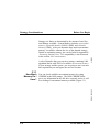
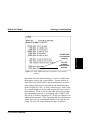
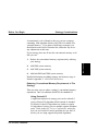
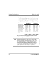
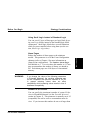
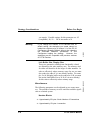
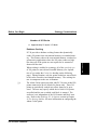
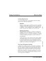
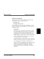
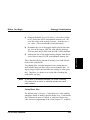
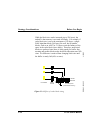
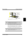
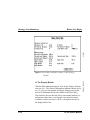
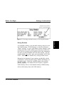
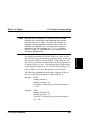
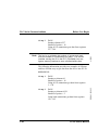
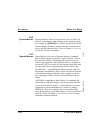
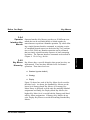
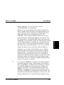
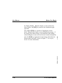
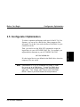
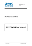
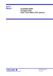
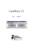
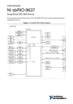
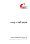
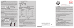
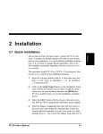
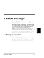
3 Before You Begin Although you can build very large strategies, there are constraints to strategy size, mainly due to memory limitations in different computers. This chapter focuses on guidelines for developing application strategies in light of possible constraints. 3.1 Strategy Considerations Before building a strategy, you should determine whether your strategy will run on the target system. Keep in mind the target system is the system you run the strategy on (not necessarily the system you build the strategy on). The two most important strategy design considerations are size and I/O compatibility. PC-30 User’s Manual 3-1 Before Starting Before you begin using PC-30, you should be familiar with its operation. The PC-30 software operates on any IBM compatible PC with 640K of conventional memory. An AT class machine (80286) or better is recommended. The Strategy Builder and the Display Builder modules operate under DOS (Version 3.0 or higher required), while a completed strategy operates under PC-30 Runtime which is invoked from DOS. Before You Begin Strategy size limits are determined by the amount of total System Memory available. System Memory includes conventional memory, Expanded Memory (LIM 4.0 EMS), and eXtended Memory (XMS). After you determine how much conventional memory is available, estimate the size of the planned strategy. Details on estimating strategy size can be found in Appendix E: Estimating Database Size. I/O compatibility is also discussed in the section, I/O Considerations. A rule of thumb is that you can run a strategy containing 1000 algorithm blocks with 550 K of available conventional memory. If your strategy and the system you are going to run it on meet this requirement you can bypass the next two sections. 4/23/93 Strategy Considerations 3.1.1 You can check available conventional memory by typing CHKDSK at the DOS prompt. The DOS CHKDSK utility gives you information on the disk drive currently active as well as a reading of conventional memory available (Figure 3.1). RG-GA3-030-005 How Much Memory Do I Have? 3-2 PC-30 User’s Manual Strategy Considerations 640 KB total conventional memory 551 KB available conventional memory Figure 3.1 DOS CHKDSK shows available conventional memory Remember that conventional memory available is 640K minus the memory used by any system utilities. System utilities include DOS itself, DOS buffers, and certain hardware and software utilities which may be allocated to conventional memory in the CONFIG.SYS file. A utility which sets up a Disk Cache, for example, might use at least 64K and possibly more conventional memory. Even if you have no other special devices that use conventional memory, as a minimum, your CONFIG.SYS file sets up 15 buffers required for PC-30 (refer to Chapter 2 for additional information). TSR (Terminate and Stay Resident programs) also takes up conventional memory even when not executing. Be sure you are not loading this type of software. PC-30 User’s Manual 3-3 Before Starting Before You Begin Strategy Considerations If necessary you can reduce the number of buffers to get more conventional memory. Reducing the number of buffers may degrade the operating speed of the software. In no case should you reduce the buffers less than 10. If you have EMS memory installed in your PC, you can load some of these utilities into EMS memory and thus not use up valuable conventional memory. Find details on how to do this in the documentation for your particular Expanded Memory Manager program. Note 4/23/93 Note Before You Begin If you are going to run large strategies, avoid using DOS 4.0 or higher which uses more conventional memory than DOS 2.X or 3.X. 3.1.2 DOS 3.3 60 KB PC-30 RUNTIME 425 KB DATA BASE SPACE AVAILABLE: 155 KB 640 KB Figure 3.2 Typical PC-30 Runtime system memory allocation 3-4 PC-30 User’s Manual RG-GA3-030-005 Figure 3.2 shows the allocation of conventional memory during a PC-30 Runtime session. DEVICE DRIVERS How Much Memory Do I Need? Before You Begin Strategy Considerations As mentioned, a rule of thumb is that you can run a strategy containing 1000 algorithm blocks with 550K of available conventional memory. If you plan to build larger strategies you should make some kind of estimate first, and make any necessary adjustments at this time. If your strategy does not fit into the conventional memory available you can: Reduce the conventional memory requirement by tailoring your strategy 2. Add EMS system memory 3. Add XMS system memory 4. Add both EMS and XMS system memory Before Starting 1. Detailed information on adding memory and memory usage is found in Appendix F: XMS and EMS Memory. Reducing Conventional Memory Requirement in The Strategy There are many ways to reduce a strategy’s conventional memory requirement. One is to substitute Packed I/O for standard I/O. Using Packed I/O A significant reduction in strategy size can be realized if you use Packed I/O algorithm blocks instead of standard I/O blocks. Packed I/O algorithms are similar to regular I/O algorithms, but they process multiple signals simultaneously. Refer to the PLC Driver Compatibility section before you use Packed I/O and in particular be sure the I/O drivers you are using support the packed algorithms. PC-30 User’s Manual 3-5 Strategy Considerations Before You Begin The following example gives an estimate first using standard and then using Packed I/O. There are 40 analog inputs, 22 analog outputs, 70 digital inputs, and 30 digital outputs. For this application data is logged on all analog inputs, analog outputs, and 50 calculated process points. 40 analog inputs 22 analog outputs 70 digital inputs 30 digital outputs 1 device drvr. block 6 history blocks 20 F(x) blocks 80 misc. digital blocks Packed I/O 40 AIN 22 AOUT 70 DIN 30 DOUT 1 DEV 6 HIST 20 F(x) 80 Slogic 6120 2442 9030 3510 120 10692 8400 5400 5 PAIN 3 PAOT 5 PDIN 2 PDOT 1 DEV 6 HIST 20 F(x) 80 Slogic 2720 1320 650 460 120 10692 8400 5400 Total 46182 Total 30230 4/23/93 Standard I/O Note 3-6 As entered, descriptions for each point in a packed algorithm block increases the block size by 31 bytes. The size increases according to the last description entered, even if some descriptions are skipped (e.g. if only the 3rd point is given a description, the size increases by 3 * 31 = 93 bytes). Descriptions are entered when configuring the algorithm block (See Chapter 6: Algorithms). PC-30 User’s Manual RG-GA3-030-005 The use of Packed I/O blocks instead of regular I/O blocks results in a savings of over 15K of memory. Before You Begin Strategy Considerations Alarm Pages Reduce the number of alarm pages to the minimum needed. This parameter is set in the Event Configuration submenu (refer to Chapter 4 for more information on Alarm-Event configuration). The Number Alarm Pages field defaults to 3. You can reduce this number to 1 if one page accommodates the number of alarms you intend to use. Each alarm page uses 1640 bytes of conventional memory. WARNING If you change the values of the following parameters in Extended Metaconf, the resulting strategies may not be compatible with previous versions of PC-30. In general reducing values does not affect compatibility while increasing values results in loss of downward compatibility. Number of I/O Devices You can specify the (maximum) number of system I/O devices in Extended Metaconf (see the Extended Metaconf section in Chapter 2). This parameter is normally set to 42 (compatible) but can be reset to accommodate more devices. If you increase this number do not set it larger than PC-30 User’s Manual 3-7 Before Starting Using Small Logic Instead of Standard Logic You can save 61 bytes of data space per logic block by using small logic blocks instead of the standard logic block counterparts. Small logic blocks have several limitations which you must consider before using them (see the section, Small Logic Algorithms). Strategy Considerations Before You Begin Warning If you change the number of I/O devices from its default setting, the strategies you create cannot be loaded into versions prior to Version 3.1 of the PC-30 Configurator (Strategy Builder) without also changing the Extended Metaconf parameters of the Configurator loading the strategy. However, the strategies are still compatible with previous versions of PC-30 Runtime. 4/23/93 you require. Possible settings for this parameter are: 42 (compatible), 48; 56 ... 120 in increments of 8. Miscellaneous The following parameters can be adjusted to save some memory. The amount of memory saved is small but could be significant on a limited system. Number Blocks 3-8 • Approximately 35 bytes / block Number of Connections • Approximately 15 bytes / connection PC-30 User’s Manual RG-GA3-030-005 Link Buffer Size, Display Size These two parameters, although not functionally related, are allocated to the same memory area. The memory used for either will therefore be the larger of either numbers. In order to effectively reduce memory usage for one you must also reduce the other if it is not already smaller. For example, if a 64 K display buffer can be reduced to 34 K you must also set the Link Buffer Size to 34 K (if it is not so already) for this value to effectively reduce memory usage. Before You Begin Strategy Considerations Number of I/O Blocks • Approximately 22 bytes / I/O block PC-30 provides a database caching feature that dynamically caches I/O points from conventional memory to extended memory. This feature reduces the conventional memory overhead requirement in applications where the I/O point counts are high, but where all of the points are not required to be scanned or alarmed all the time. When caching is enabled in a strategy, all of the specified type of I/O points are moved into Extended Memory (see explanation of type under the Cache Size heading on the following page). During Runtime, only the points needed are moved back to the cache created in conventional memory. The caching feature is transparent to the user in Runtime. ☞ The Alarm Cache option provided with PC-30 scans cached I/O points connected to device blocks for alarms only. These I/O points are periodically cached in to allow alarms to be processed. The user may specify which device block’s I/O points are polled and the rate at which each block is scanned. The scan rate is set independent of the I/O Scanner and block scan rate. Refer to the Enabling PC-30 Options section in Chapter 4: The Strategy Builder for more information on configuring the Alarm Cache option. PC-30 User’s Manual 3-9 Before Starting Database Caching Strategy Considerations Before You Begin Caching Requirements Hardware Database caching requires an 80386 type of PC with XMS configured via an XMS configurator such as QEMM-386 or 386MAX. XMS configured by page swapping routines (INTEL 286 type Above Boards, etc.) do NOT work. 4/23/93 To use the caching feature, your hardware and your strategy must meet the following requirements: Caching parameters can be adjusted in the Strategy Builder SYS CNFG submenu (See SYS CNFG section in Chapter 4), and their status can be viewed in Runtime on the second page of the System Parameter subwindow (refer to the section, System Parameters in Chapter 8). Two Types Of Database Caching Caching can be enabled separately for I/O blocks and Distributed I/O. Separate caching increases flexibility and efficiency by optimizing the use of the cache buffer. I/O blocks that are cached are: AIN, AOUT, DIN, DOUT, PAIN, PAOT, PAIO, PDIN, PDOT and PDIO. Distributed (Intelligent) I/O refers to the type of device described in the section, Intelligent I/O Device Configuration in Chapter 5. 3-10 PC-30 User’s Manual RG-GA3-030-005 Strategy Parameters Strategy Database Caching is not effective if strategy I/O scanning is set to ON. (Scanning is set in SYS CNFG , under the SEL Function, I/O Scanner in Chapter 4.) Caching is effective with the I/O Scanner set either to OFF or to ON DEMAND. Before You Begin Strategy Considerations Caching Considerations When you first enable database caching the Cache Size and Cache Block Size are set at default values of: Cache Size = 64K Cache Block Size = 16 bytes Cache Size The total size of the cache buffer. This memory is taken from usable Runtime memory, therefore, if you make this too large you may not be able to run big strategies. For most strategies, you can safely allocate 64K. (There is no penalty as long as a strategy runs.) If it becomes necessary to tailor this parameter, you can change it (see Database Caching in Chapter 4 for instructions). To decide how large to make the cache buffer, estimate the number of I/O points you expect to be in cache at any time. For caching purposes, I/O points are divided into two groups: I/O points and Distributed. These groups are subdivided into two types; Static and Dynamic. Static I/O points are usually ALWAYS IN MEMORY. Therefore, these points are ALWAYS CACHED WHEN CACHING IS ENABLED. PC-30 User’s Manual 3-11 Before Starting You can adjust these values to optimize performance. Adjustments are made in the Strategy Builder SYS CNFG menu when creating the strategy. Strategy Considerations Before You Begin Static I/O points can be identified as: • ANY I/O point with FULL SCAN SET TO ON • Points required for System Trend • Points involved In connections (Source or 4/23/93 Destination) Dynamic I/O points are: Once you determine the maximum number of blocks that will be in the cache at one time, add up the byte count (refer to Block and Variable Byte Counts, Appendix E6). Since it may be difficult to estimate particular I/O points that are actually in the cache buffer at any time, you may be able to use an empirical worst case method as follows: 1) Develop the full application (strategy). Be sure caching is enabled. 2) 3-12 Invoke the strategy in Runtime. PC-30 User’s Manual RG-GA3-030-005 • Points in main or subwindow displays • Points added and removed from the System Trend • Points logged in History blocks • Points needed for external use (e.g. networking) Strategy Considerations 3) Using the Runtime System Parameters subwindows (Chapter 8), look at the LOW (conventional) memory left. Observe this value as the strategy executes. Note the SMALLEST value. (The least amount of unused memory.) 4) Determine the size of the largest display used by this strategy (size of the largest .GRP file used with the strategy). You can check this in DOS with the DIR *.GRP command. 5) Subtract the size of the largest strategy display from the observed lowest value of LOW (conventional) memory left. This is theoretically the amount of memory you could allocate to the to the cache buffer. You should allow a modest margin of error, noting that too small a buffer does not allow you to access dynamic data. Using too large a buffer does not allow the strategy to start operation. Therefore, it is better to err on the side of making the cache buffer too large. Note In the case of networked strategies, all nodes containing I/O points must be active to correctly emulate the worst case condition. Cache Block Size The default value is 16 bytes. Cache block size is the smallest contiguous chunk of memory that the buffer uses. Cache buffering is allocated in units of 1 block so small size blocks may cause excessive fragmenting of the cache (Figures 3.3 A and B). PC-30 User’s Manual 3-13 Before Starting Before You Begin Before You Begin While the block size can be increased (up to 550 bytes), the tradeoff is that memory is not used efficiently. For example, if cache block size is set to the maximum of 550 bytes, a single PAIN algorithm block (544 bytes) fits well, but all smaller blocks, such as an AOUT at 111 bytes waste the balance of the space in the cache block (leave holes). Therefore, small-sized blocks are preferred since there is little penalty for buffer fragmenting and smaller blocks make the buffer allocation more efficient. No difference is noticed from changing block size until the buffer is nearly full (90% or more). 4/23/93 Strategy Considerations CACHE I/O POINTS SMALL CACHE Unused spaces (little wasted memory) Figure 3.3A Effect of cache block sizing 3-14 PC-30 User’s Manual RG-GA3-030-005 BUFFER Before You Begin Strategy Considerations MEMORY MAY BE WASTED IF CACHE BLOCKS ARE TOO LARGE CACHE BUFFER LARGE CACHE Unused spaces Before Starting I/O POINTS (much wasted memory) Figure 3.3B Effect of cache block sizing Note ☞ Note The database caching feature requires you to have an understanding of memory management. You can monitor the actual status of cache buffer activity in Runtime using the System Parameters subwindow (Page 2) Cache Used and Largest Hole (see Chapter 8). If it becomes necessary to tailor this Cache Block Size, you can change it by reconfiguring the Cache Block Size parameter in the Configurator. (See Database Caching, Chapter 4 for instructions.) If you get a CACHE FULL! error message, you must increase the size of the cache buffer. PC-30 User’s Manual 3-15 Strategy Considerations Before You Begin 3.1.3 To add EMS memory, first add the additional memory chips you need. Then configure it to conform to the LIM 4.0 EMM specification by using a memory manager (such as QEMM from Quarterdeck). The memory manager program is installed on the hard disk and is invoked when the system is powered-up. Then, when the computer is turned on, it automatically initializes the expanded memory. XMS is a specification (from Microsoft Corp.) for utilizing the Upper Memory often included in 80286 and 80386 systems but not otherwise easily accessible. There are a number of ways to get XMS memory on 80386 systems. The most recent release of Quarterdeck’s QEMM program (QEMM-386) directly sets up XMS and EMS memory. A similar product that also works is 386MAX from Qualitas. You can also use the Microsoft HIMEM.SYS driver to implement XMS on both 80286 and 80386 machines (HI 64K memory only). PC-30 automatically detects and utilizes EMS and XMS memory when present. XMS memory is used by all PC-30 modules while EMS memory is used by the Runtime system. Memory managers must be installed to use EMS and/or XMS memory. If XMS memory is detected, PC-30 uses this memory for loading various items first. 3-16 PC-30 User’s Manual 4/23/93 If you cannot run a strategy with the existing amount of conventional memory on your target system because the display is too big or you are out of memory, you can add EMS and/or XMS memory. EMS memory is a paged memory system defined by the LIM standard. XMS refers to the memory that resides above the conventional memory (640 KB). RG-GA3-030-005 Adding EMS And/Or XMS Memory Before You Begin Strategy Considerations Conventional memory is used only after all available XMS memory is filled, thus freeing up a considerable amount of conventional memory. If EMS memory is present, PC-30 Runtime loads high (puts into EMS) a portion of certain drivers and options thus freeing up conventional memory. Checking Memory Usage In The Strategy Builder With the Edit submenu displayed, click on the Memory Status icon (%). The Memory Status submenu shown in Figure 3.4 gives you a complete set of memory statistics. See the Edit Function section in Chapter 4: The Strategy Builder for more information on the EDIT mode. PC-30 User’s Manual 3-17 Before Starting In this way, you can run larger strategies or operate a given strategy more efficiently. Refer to Appendix F: XMS and EMS Memory Support for more detailed information. Before You Begin 4/23/93 Strategy Considerations Figure 3.4 Checking available memory in the Strategy In The Display Builder With the Edit submenu displayed, click on the Display Information icon (%). The Display Information submenu shown in Figure 3.5 gives you the amount of Display Memory used as the percent of Maximum (buffer size allotted in METACONF). Note that this does not directly affect conventional memory requirements unless there is not enough conventional memory available in which case there will be a consequent increase in the display buffer size. 3-18 PC-30 User’s Manual RG-GA3-030-005 Builder Before You Begin Strategy Considerations Display memory used as a function of allotted buffer size During Runtime As you build a strategy, you can check memory usage by creating a Null Strategy. A Null Strategy is created by saving an “empty” strategy. To get a good memory usage estimate, a null strategy must have all the options you want to use enabled, all device drivers you plan to use installed, and all the communication ports you need installed with scan times entered. The I/O scanner should not be ON. Also, you must build a NULL DISPLAY. Make a NULL DISPLAY by saving a blank screen. During the development of your strategy, periodically exit the Configurator, and run the null strategy with the null display on the target system. Check the available memory by pressing [Alt-A], [PgDn]. The display shown in Figure 3.6 appears. LOW memory refers to conventional memory; HIGH memory refers to all memory above the LOW memory. PC-30 User’s Manual 3-19 Before Starting Figure 3.5 Checking available memory in the Display Builder PLC Serial Communications Runtime Memory Status Before You Begin 5.00 4/23/93 Figure 3.6 Checking available memory in the Runtime system 3.2 PLC Serial Communications • Packed I/O • Contiguous memory locations in the PLC • Using All 16 points in every group when possible • On demand scanning Packed I/O Advantages The advantage of using packed I/O instead of standard I/O is that it is significantly faster than individual I/O blocks. When a point in a packed block goes into alarm, the Alarm/ Event summary reports the tag name of the packed block in alarm, the block input in alarm (AI1 - AI8 or DI1 - DI16), and the unique description of this input (if entered during block configuration). 3-20 PC-30 User’s Manual RG-GA3-030-005 There are several fixed factors that affect the communications speed: baud rate, speed of the computer, etc. However, there are more efficient ways to get I/O information into PC-30: Before You Begin Individual point descriptions in packed blocks increase the block size. As entered, each description will increase the block size by 31 bytes. The size will increase according to the last description entered, even if some descriptions are skipped (e.g. if only third input is given a description, the size increases by 3 * 31 = 93 bytes). Refer to Chapter 6: Algorithms for more information on configuring packed blocks. If a strategy uses packed I/O (PAIN, PDIN, etc.) with 16 connections in it to 16 packed blocks, each group brings in 128 registers (words) PAIN or 256 bits (PDIN). If the group uses I/O (Ain, Din, etc.) and has 16 connections in it, the group brings in 16 words (AIN) or 16 bits. If each group takes a fixed amount of time and packed brings in 128 (or 256) and I/O brings in 16 (AIN or DIN), it is obvious that packed is more efficient. The following information provides three examples of the correct way to get data from the device block into PC-30: Group 1 PAIN Starting element #1 Number of points = 16 Using all 16 connections gets data from registers 1 - 128 Group 2 PAIN Starting element #129 Number of points = 16 Using all 16 connections gets data from registers 129 - 256 PC-30 User’s Manual 3-21 Before Starting Note PLC Serial Communications PLC Serial Communications Note PAIN Starting element #257 Number of points = 16 Using all 16 connections gets data from registers 257 - 384 The key is to minimize the number of groups and maximize the number of connections per group. You should consider moving the I/O in the PLC (if possible) into contiguous memory locations to save communications time. 4/23/93 Group 3 Before You Begin The following information provides two examples of efficient and less efficient ways to get data from the device into PC-30: 3-22 Group 1 PAIN Starting at element #1 Number of points = 16 Using all 16 connections get data from registers 1 - 128 Group 2 PAIN Starting at element #129 Number of points = 2 Using both connections get data from registers 129 - 145 PC-30 User’s Manual RG-GA3-030-005 EFFICIENT: Before You Begin PLC Serial Communications Group 1 PAIN Starting element # 1 Number of points = 9 Using all 9 connections gets data from registers 1 - 72 Group 2 PAIN Starting element #73 Number of points = 1 Using 1 connection gets data from registers 73 - 80 PLC Integer File The following information provides two examples of efficient and less efficient ways to get data from the device into PC-30: EFFICIENT: Group 1 PAIN Starting element #1 Number of points = 16 Using 16 connections gets data from registers 1- 128 Group 2 PAIN Starting element #129 Number of points = 9 Using 9 connections gets data from registers 129 - 200 PC-30 User’s Manual 3-23 Before Starting LESS EFFICIENT: PLC Serial Communications Before You Begin PAIN Starting element #1 Number of points = 1 Using 1 connection gets data into registers 1- 8 Group 2 PAIN Starting element #9 Number of points = 1 Using 1 connection gets data into registers 9 - 16 Group 3 PAIN Starting element #17 Number of points = 10 Using 1 connection gets data into registers 17 - 97 RG-GA3-030-005 Group 1 4/23/93 LESS EFFICIENT: 3-24 PC-30 User’s Manual Before You Begin PLC Serial Communications Communications Scan Times As a rule of thumb, the scan frequency of the algorithm block should be set at a rate that is half the communications scan frequency. This ensures that the block obtains data from every communications scan. Experiment with various scan frequencies to obtain optimum communication efficiency. Figure 3.7 shows the relationship between the communication port scan time and the algorithm block scan time. Data from all the comm port scans is read by block #1 Block #1 scan frequency (1 sec.) COM port scan frequency (2 sec.) 0 sec Block #2 scan frequency (3 sec.) 2 sec 4 sec 6 sec 8 sec ? Data from the comm port scan at 4 seconds is never read by block #2 Figure 3.7 Relationship between algorithm block scan time and the communication port scan time PC-30 User’s Manual 3-25 Before Starting Drivers perform communication transfer differently. Most PLC communications attempt to transfer data one group at a time. It takes a fixed amount of time (per driver) to scan one group of a device block. However, this does not mean that all data is transferred in one request or that data can be transferred in a fixed amount of time. I/O Considerations Before You Begin 3.3 I/O Considerations 3.3.1 The PC-30 software directly supports numerous I/O devices including: • Plug-in I/O boards • Programmable logic controllers • Single loop controllers • Intelligent I/O devices 4/23/93 Device Drivers It is likely that the interface hardware you are using or plan to use is supported by a standard PC-30 Device Driver. In the event that your I/O device is not supported by a stock driver, the PC-30 Device Driver Tool Kit allows you to create you own custom drivers. Before you begin building a strategy, be sure you have the correct device driver or drivers you need to interface to your control system hardware. Also be sure you have the documentation that accompanies each device driver. You must have the User’s Guide for the device driver you are using for specific information on that driver. (This manual contains only general information on device drivers.) 3-26 PC-30 User’s Manual RG-GA3-030-005 For any particular device, you must use the matching device driver. When you purchase PC-30 you get 1 driver of your choice. You can also order any number of additional drivers from our extensive selection of device drivers. Before You Begin I/O Considerations With the proper device driver software installed on your system, you can configure the device by stepping through a series of menus, including the specific device configuration menu which prompts you for all necessary device interface parameters. It is recommended that you try to establish communications with the device in a small test strategy before you develop a large strategy. I/O device configuration is described in detail in Chapter 5 and the driver documentation included with the driver. 3.3.2 PLC Device Driver Compatibility PLC devices may not be fully compatible with all algorithm blocks. To determine compatibility: 1. Check the device driver documentation. 2. With the device driver installed, review the Signal Type Field as follows: Set up the device block according to the instructions in Chapter 5. In the Group Configuration Window. select the Signal Type Field and successively click the left mouse key while pointing to this field. This sequences you through all of the algorithm blocks that are compatible with the particular device. PC-30 User’s Manual 3-27 Before Starting Note I/O Considerations Before You Begin 3.3.3 Individual alarms can be set up for different conditions associated with most algorithm blocks. You should be aware of the following when preparing to use alarms: The block scan rate determines how often a particular block is polled for alarms. However, the I/O Scanner determines how often PC-30 uploads/downloads data to/from the device. Therefore, for alarming purposes the period for the block scan should be less than or equal to the scan rate for system (I/O scanner). 4/23/93 Alarms Select an alarm scan rate that is sufficient to alert you in time. Be aware that the I/O scanner also has two operating modes: ON - all alarms (and other I/O data functions) are polled periodically based on the I/O Scanner rate. • Linked to a current display (a display which is on the screen). • On System Trend • Actively being logged by a Historian block • Being used by the Network or Report and Recipes options You can, however, override this condition on a block-by-block basis. If you want to have an alarm polled at all times, even with the scanner is set to ON DEMAND, set FULL SCAN = Y in the respective block’s configuration menu. 3-28 PC-30 User’s Manual RG-GA3-030-005 ON DEMAND - The block is scanned when it meets one or more of the following criteria: Before You Begin Note If the PC-30 database caching feature is used in conjunction with ON DEMAND scanning, cached I/O points associated with a device block can be polled for alarms provided the Alarm Cache option is enabled in the Strategy Builder when creating the strategy. This option allows the user to specify device blocks which will have their I/O points periodically cached in for the purpose of processing alarms. Refer to the Enabling PC-30 Options section in Chapter 4: The Strategy Builder for more information regarding the Alarm Cache option. Before Starting ☞ I/O Considerations The scan rate at which the cached I/O points are polled for alarms is independent of the I/O Scanner rate or the block scan rate. The scan rate is specified on a block by block basis when configuring the Alarm Cache option. 3.3.4 Strategy Interfacing When connecting device blocks keep the following rules in mind: The following device types do require I/O Algorithm Blocks to interface into a strategy: Programmable Logic Controllers Plug-in I/O boards The following device types do not require standard I/O Algorithm Blocks to interface into a strategy. These devices can be interfaced directly to function algorithm blocks such as F(x), LLAG, PID etc. Loop Controllers Intelligent I/O Devices PC-30 User’s Manual 3-29 Key Macros Before You Begin A macro is a set of instructions that can be invoked by a single keystroke. With Key Macros, a single key can be defined to bring up a unique display, copy files to a disk, initiate a History Replay, or perform any other operation that previously required a sequence of keystrokes. When Key Macros are combined with the Touch Screen option and Pick Fields, you can touch the display screen to execute the desired operation. 4/23/93 3.4 Key Macros • Display • System • Named • Operator Interface Each of these Key Macro types can function individually or with other types during the PC-30 Runtime System to perform the desired operation. When configuring a Key Macro within the Display Builder, the submenu shown in Figure 3.8 shows that the first entries are: DISPLAY for operator display-based operations, SYSTEM for the PC-30 software system screen operations, MACRO for Named Macro execution, and lastly the Operator Interface Commands appearing in alphabetical order. 3-30 PC-30 User’s Manual RG-GA3-030-005 PC-30 has four types of Key Macros that can be implemented into the system: Key Macros Before Starting Before You Begin Figure 3.8 Key Macro Functions submenus 3.4.1 Display Key Macros Display-based Key Macros allow you to bring up a specific operator graphic display generated by the Display Builder onto the Runtime screen with a single keystroke. For example, the [F10] key could be defined to show a specific operator graphic display using the Display Operator Interface command. Refer to Chapter 4: The Strategy Builder and Chapter 7: The Display Builder for more information. PC-30 User’s Manual 3-31 Key Macros Before You Begin 3.4.2 3.4.3 Named Macros Named Macros are a series of Operator Interface commands that are linked together to perform a single operation. There is no limit to the number of commands that can be used to perform a single operation. Named Macros must be configured in an external ASCII text source file and compiled with other strategy-based Key Macros assignments by the Key Macro Compiler KEYMAC. Compiled Named Macros and any other key assignments within that Key Macro source file must be attached to the desired strategy so that they can be assigned to any key, key combination, or Pick Field to perform the defined operation(s). A KEYMAC-compiled Key Macro library file containing the Named Macros and other Display- and System-based Key Macros can be attached to a strategy. A Named Macro can also be configured to execute automatically by means of a strategy DISP block. Based on a digital event, a Named Macro that exists in that strategy’s Key Macro library can be executed automatically. Refer to Chapter 4: The Strategy Builder for more information on Named Macros. 3-32 PC-30 User’s Manual 4/23/93 System-based Key Macros provide access to any of the PC-30 software system displays and submenus with a single keystroke. For example, the [Shift-F2] key could be defined with a named macro to display the History Replay submenu, select the file to replay, and then start the replay. Refer to Chapter 4: The Strategy Builder for more information. RG-GA3-030-005 System Macros Before You Begin Key Macros 3.4.4 Operator Interface Key Macros provide over 50 different commands that can be used individually or linked together by named macros to perform a Runtime operation. By either defining a single Operator Interface command, or assigning a series of commands (named macros) to the desired key, key combination, or Pick Field, any Runtime operation can be performed that previously required an entire sequence of time-consuming keystrokes. The Operator Interface commands are described in Chapter 4: The Strategy Builder. 3.4.5 Key Macro Hierarchy Key Macros have a specific hierarchy that govern how they are implemented. There are three different levels for Runtime operations. These three levels are: • Standard (system default) • Strategy • Display Figure 3.9 shows how each of the Key Macro levels overrides the other levels. As shown, the Standard Key Macros are the lowest level Strategy-based Key Macros (if a strategy Key Macro library is declared) override only the matching Standard assignments and finally, the Display-based Key Macros, the highest Key Macro level, override both the Strategy and Standard Key Macro assignments. If Strategy Key Macros do not exist, Display Key Macros override the matching Standard Key Macros. PC-30 User’s Manual 3-33 Before Starting Operator Interface Key Macros Key Macros Before You Begin 4/23/93 All functions in Runtime are key macros defined in STANDARD.KML. If you create your own key macros, you should use the strategy name in place of STANDARD. STANDARD KEY MACROS [CR = DOWNLD_p [?] = SCREEN (H [HOME] = STRATEGY KEY MACROS DISPLAY KEY MACROS Figure 3.9 Structure of Key Macro levels PC-30 provides a standard Key Macro library (STANDARD.KML) that contains the default assignments for all of the keyboard and mouse functions for Runtime operation. The standard Key Macro library is always used as defining the lowest level of Key Macro operations. Unless they are overridden by either a Strategy-based or Display-based Key Macro or both, the Standard Key Macro assignments are always in effect. 3-34 PC-30 User’s Manual RG-GA3-030-005 Note Before You Begin Key Macros When you create your own Key Macro library using the Key Macro Compiler utility (KEYMAC) and attach the library to a specific strategy, the key assignments and Named Macros defined replace only those key assignments in STANDARD.KML. These strategy-based Key Macros are in effect upon the strategy’s start up in the Runtime environment. The key assignments in STANDARD.KML that are not replaced by assignments in your attached strategy Key Macro library remain in effect during Runtime or until they are overridden by a Display Key Macro. The creation and implementation of strategy Key Macros are described in Chapter 4: The Strategy Builder. Display Key Macros are in effect only while the display in which they were created is on the Runtime screen. Displaybased Key Macros are created in operator displays using the Display Builder. Existing Display Key Macros override any matching strategy Key Macros as well as any standard Key Macros only while that particular display is on the screen when the display changes, the strategy’s Key Macro library assignment (if there is one), as well as any standard assignments that were not overwritten, are restored. ☞ For example, the [F10] key is defined in an operator display to download a data entry value. In that strategy’s Key Macro library, the [F10] key is defined to place the strategy in simulation mode by toggling the I/O scanner input variable to that strategy’s SYS block. The standard Key Macros define the [F10] key to toggle the current block between Remote and Local modes. The [F10] key combination performs the data entry download only when the operator display is on the screen. Display-based Key Macros are created in operator displays using PC-30 User’s Manual 3-35 Before Starting Refer to Chapter 4: The Strategy Builder for the STANDARD.KML key assignments. Key Macros Before You Begin RG-GA3-030-005 The standard [F10] key operation of toggling the current block’s Remote/Local mode is not used within this strategy. If the strategy Key Macro library is not attached to this strategy when the display is removed from the main window during Runtime, the [F10] key toggles the current strategy block between Remote and Local mode. Refer to Chapter 7: The Display Builder for more information. 4/23/93 the Display Builder. When the display is removed from the main window, the [F10] key returns to the simulation toggle operation. 3-36 PC-30 User’s Manual Before You Begin Configurator Optimization 3.5 Configurator Optimization Then, you need to use the DOS SET command to assign the logical drive in your AUTOEXEC.BAT file. For example, you might add this statement to your AUTOEXEC.BAT file: SET PC30TMP=D:\ D is the logical device you defined as the RAM drive where the temporary files are stored. Note Performance of PC-30 is increased only when a TEMP file is set up in a RAM drive. To see if a RAM drive exists, at the DOS prompt change to the RAM drive and type DIR. The volume label should state MS-RAMDRIVE. Refer to your DOS manual for this procedure. PC-30 User’s Manual 3-37 Before Starting To achieve optimum performance and speed of the PC-30 Configurator, you can set up a RAM drive where temporary files are stored. To do this, you need to define a RAM drive in your CONFIG.SYS file. Shared File Support Before You Begin Files created during Runtime (history files, alarm logs, etc.) can be viewed on a remote node while Runtime still has the file(s) open. This function is used in conjunction with the DOS SHARE.EXE utility which allows files on a DOS node to be “shared”, i.e. viewed by a remote application such as a text editor while the file is already opened in another application (Runtime). 4/23/93 3.6 Shared File Support ☞ Important! 3-38 Altering the shared file in the remote application (e.g. text editor) is not permissible. Any attempt to alter the file will result in an error message from the text editor. Any attempt to open a shared file in an editor that does not support shared file access will also result in an error message. The DOS file-sharing utility (SHARE.EXE) must be installed on the PC executing PC-30 Runtime. If the file-sharing utility is not installed, Runtime will abort execution during initialization. Refer to the DOS Technical Manual for information regarding the installation of SHARE.EXE. PC-30 User’s Manual RG-GA3-030-005 The Runtime files logged to the shared node can be viewed by the PC-30 List and History Replay functions as well as text editors that support shared file access (e.g. LIST and EDIT). If Runtime continues to write to the file, the remote application viewing the shared file will not see the updates until it closes and then reopens the file. Before You Begin ☞ Shared File Support PC-30 allows the user to specify the directories that history files and alarm files are logged to when creating your strategy in the Strategy Builder (see the System Configuration section in Chapter 4: The Strategy Builder). This feature enables Runtime to log alarm and history files to file servers that support file-sharing. An example PC-30 network configuration is shown in Figure 3.10. Master PC-30 node running a strategy Before Starting (SHARE.EXE must be installed) VERSION 5.0 ABB Kent-Taylor File Server (SHARE.EXE must be installed) ARCNET • Ethernet PC-30 node viewing a shared file NOVELL • Token Ring DOS node viewing a shared file DOS node viewing a shared file (Via text editor) (Via text editor) (Via List File or History Replay) Figure 3.10 Example network configuration for accessing shared files PC-30 User’s Manual 3-39 Calling Technical Support Before You Begin 3.7 Calling Technical Support • The version number for the PC-30 software you are running (Drivers, Options, etc.) • The serial number on the copy protection key • The type of PC you are using with as much system information as you can provide: total amount of memory (use CHKDSK /F) conventional memory available XMS or EMS memory processor speed • Type(s) of I/O hardware used or going to be used • The device driver(s) you are using or plan to use (include the version number) Once you have this information together, you can call your local authorized PC-30 service representative. 3-40 PC-30 User’s Manual RG-GA3-030-005 - 4/23/93 If you need to call for technical support, make sure you have the following information available: