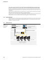
1
FOUNDATION™ FIELDBUS DIAGNOSTIC POWER CONDITIONER SYSTEM FIELDBUS POWER SUPPLY DPC-49-4RMB USER MANUAL Edition 03.12 © Hans Turck GmbH, Mülheim an der Ruhr All rights reserved, including those of the translation. No part of this manual may be reproduced in any form (printed, photocopy, microfilm or any other process) or processed, duplicated or distributed by means of electronic systems without written permission of Hans Turck GmbH & Co. KG, Mülheim an der Ruhr. Subject to alterations without notice. II D301164 0312 - FF Diagnostic Power Conditioner System Warning! Before beginning installation work Disconnect the device from the power supply Protect against accidental restart Verify isolation from the supply Earth and short-circuit the supply Cover or close off neighbouring units that are live. The assembly instructions provided for the device are to be complied with. Only suitably qualified personnel according to EN 50 110-1/-2 (VDE 0105 part 100) are authorized to carry out work on this device/system. When conducting installation work ensure that you are free of electrostatic charge before touching the device. The functional earth (FE) must be connected to the protective earth (PE) or the equipotential bonding. The system installer is responsible for establishing this connection. Connection and signal cables are to be installed so that any inductive or capacitive interference does not impair the automation functions. The installation of automation devices and their operating elements is to be carried out in such a way as to prevent unintentional operation. In order to prevent cable or wire breakage on the signal side generating undefined states in the automation devices, appropriate safety measures are to be taken for the I/O coupling on the hardware and software side. Ensure a reliable isolation of the extra-low voltage for the 24 V supply. Only those power supply units that comply with IEC 60 364-4-41, i.e. HD 384.4.41 S2 (VDE 0100 part 410) are to be deployed. Fluctuations or deviations of the mains voltage from the nominal value should not exceed the tolerance limits specified in the technical data, otherwise malfunctions and dangerous states may occur. Emergency stop devices complying with IEC/EN 60 204-1 must remain effective in all operating modes of the automation installation. Releasing the emergency stop devices must not cause a restart. Devices for mounting in housings or cabinets, desktop or portable units, are only to be operated and controlled with the housing closed. Measures are to be taken to ensure the correct restarting of a program following interruption due to a voltage drop or failure. Dangerous operating conditions, even short term, should not occur as a result. If required an emergency stop should be carried out. External measures are to be implemented at those locations where faults in the automation installation could lead to injury to persons or damage to property. These measures must guarantee safe operating conditions even in the event of a fault or malfunction (e.g. by means of independent limit switches or mechanical locking devices etc.). The electrical installation must be carried out in accordance with the relevant regulations (e.g. in respect of the cable cross sections, uses and protective earth connections). All work involving transport, installation, commissioning and maintenance is to be carried out exclusively by qualified personnel. (in accordance with IEC 60 364 i.e. HD 384 or DIN VDE 0100 and national accident prevention regulations). All covers and doors must be kept closed during operation. D301164 0312 - FF Diagnostic Power Conditioner System III IV D301164 0312 - FF Diagnostic Power Conditioner System 1 About this manual 1.1 Description of symbols used .................................................................................................................. 2 1.2 Introduction ........................................................................................................................................... 2 2 Introduction 2.1 Characteristics ....................................................................................................................................... 2 2.1.1 2.1.2 Extended diagnostics................................................................................................................................................................................2 – Functionality ...........................................................................................................................................................................................2 Simple diagnostics.....................................................................................................................................................................................4 2.2 System overview .................................................................................................................................... 4 2.3 Figure DPC-49-4RMB.............................................................................................................................. 5 3 Mounting and installation 3.1 System components............................................................................................................................... 2 3.2 Dimensional drawing............................................................................................................................. 2 3.3 Connections and components of the DPC-49-4RMB .............................................................................. 2 3.3.1 3.3.2 3.3.3 3.3.4 3.3.5 3.3.6 DPC-49-IPS - Electrically isolated power supply (Fieldbus power supply) ............................................................................3 Blind modules for unused slots.............................................................................................................................................................4 H1 connections to the host ....................................................................................................................................................................4 H1 connections into the field.................................................................................................................................................................5 Power supply ...............................................................................................................................................................................................5 – EMC filter and overvoltage protection .......................................................................................................................................... 6 Power supply concept..............................................................................................................................................................................7 3.4 Shielding ................................................................................................................................................ 8 3.5 Earthing ................................................................................................................................................. 9 3.6 LEDs of the DPC-49-IPS module ............................................................................................................. 9 D301164 0312 - FF Diagnostic Power Conditioner System V VI D301164 0312 - FF Diagnostic Power Conditioner System 1 About this manual 1.1 Description of symbols used .................................................................................................................. 2 1.2 Introduction ........................................................................................................................................... 2 D301164 0312 - FF Diagnostic Power Conditioner System 1-1 About this manual 1.1 Description of symbols used Danger Risk of personal injury Proceed with special caution. This sign is placed next to a warning indicating a potential hazard. This refers to possible personal injury or death which may occur if the warning instructions are not observed. The user should interpret this symbol as follows: Exercise extreme caution. Attention Risk of damage to the device Proceed with special care. This sign is placed next to a warning indicating a potential hazard. This applies to possible damage to systems (hardware and software) and installations. Note This symbol is placed next to general instructions that indicate important information on the procedure for one or several operations. The relevant instructions can facilitate work and possibly help to avoid additional work resulting from faulty procedures. 1.2 Introduction This manual contains all the necessary information concerning the intended usage of TURCK products for the FOUNDATIONTM fieldbus system “Diagnostic Power Conditioner”. It has been specially developed for qualified personnel who have the required level of expertise. Chapter 2 is designed to familiarize you with the products and to show their most important features. Chapter 3 is intended to support correct mounting and installation. Danger The devices described in this manual must be used only in applications prescribed in this manual or in the respective technical descriptions, and only in connection with components and devices from third party manufacturers that have been certified.. Appropriate transport, storage deployment and mounting as well as careful operating and thorough maintenance guarantee trouble-free and safe operation of these devices. Danger It is imperative that all respective safety measures and accident protection guidelines be adhered to. 1-2 D301164 0312 - FF Diagnostic Power Conditioner System 2 Introduction 2.1 Characteristics ....................................................................................................................................... 2 2.1.1 2.1.2 Extended diagnostics................................................................................................................................................................................2 – Functionality ...........................................................................................................................................................................................2 Simple diagnostics.....................................................................................................................................................................................4 2.2 System overview .................................................................................................................................... 4 2.3 Figure DPC-49-4RMB.............................................................................................................................. 5 D301164 0312 - FF Diagnostic Power Conditioner System 2-1 Introduction 2.1 Characteristics The DPC system (Diagnostic Power Conditioner system) is a power supply system for establishment of FOUNDATIONTM fieldbus H1 segments. It provides comprehensive diagnostic features for monitoring of FOUNDATIONTM fieldbus segments and thus supports asset management across the entire system. A DPC system consists, for example, of one or more DPC-49-4RMB… module racks each with up to eight DPC-49-IPS power supply modules. For each module rack up to four H1 segments can be operated and monitored redundantly on the FOUNDATIONTM fieldbus. The diagnostic data from the H1 segments are collected via a diagnostics module (DPC-49-ADU) inserted in the module rack and transmitted to the HSE interface module DPC-49-HSEFD/24VDC. The raw data is processed in the DPC-49-HSEFD/24VDC and transferred to the higher-level asset management system. For simple redundant monitoring of the power supply modules, only the diagnostics module (DPC-49-DU) is required which signals an alarm message via a relay contact. 2.1.1 Extended diagnostics TURCK has developed the FOUNDATIONTM fieldbus Diagnostic Power Conditioning System (DPCSystem) in order to detect long-term malfunctions on a H1 FOUNDATIONTM fieldbus segment. The DPC system is intended – in addition to supporting commissioning of a fieldbus system – to detect creeping changes within individual fieldbus segments over an extended time period, and to provide suitable warning messages to prevent malfunctions or faults. With the modular FOUNDATIONTM fieldbus HSE Field Device developed by TURCK, diagnostics information concerning the Physical Layer of up to 16 H1 segments are accessible to an asset management system. The asset management system contains information about the Physical Layer of the H1 segment, whereby this asset becomes manageable in an asset management system increasing the availability of the system. The physical level of the fieldbus and as a result the communication of the fieldbus can be interrupted due to external influences. These external influences often cause unexpected failure after prolonged periods. Examples for these types of influences are: Aging of cables (possibly accelerated by moisture) Plug connectors which become loose (particularly due to vibration) Insufficient earthing and shielding which becomes evident when there are changes in the electromagnetic conditions. Cables with incorrect capacitive and inductive values Aging of communication electronics Functionality A slot for a diagnostic module is located on every motherboard (DPC-49-ADU or DPC-49-DU). The ADU (“ADU - Advanced Diagnostics Unit“ refer to the Glossary of the D301163) can successively multiplex each segment and collect large volumes of information. This information is sent to the intelligent HSE field device (DPC-49-HSEFD/24VDC) and evaluated there. 2-2 D301164 0312 - FF Diagnostic Power Conditioner System Characteristics The following are measured: Ambient temperature of the system External voltage supply A External voltage supply B Level of the segment current Number of all active H1 devices in a H1 segment LAS signal level Noise voltage Jitter Ripple Lowest signal level Highest signal level Device address of the device with the lowest signal level. The following are counted: Number of all received Frames Number of CRC faults Sequence error (when a Return Token Frame does not follow a Pass Token Frame) Number for IDLE Frames Number of Frames which are not contained in the table “possible Frames, which can follow a “Pass Token” (see manual D301163) Number of messages of type “Pass Token” Number of messages of type “Return Token” Number of messages of type “Time Distribution” Number of messages of type “Compel Data” Number of messages of type “Data_1 / Data_2” Number of messages of type Data 3 and Data 5 Number of messages of type “Disconnect Connection” Number of messages of type “Establish Connection” The following are determined: Bus loading via “Link Maintenance Frames” Bus loading with “Cyclic Frames“ Bus loading with “Acyclic Frames“ Bus loading with “Idle Frames“ Share of unused bus time “Idle Time” Note Explanations for the measured values, message types and frames can be found in the Glossary of manual D301163. D301164 0312 - FF Diagnostic Power Conditioner System 2-3 Introduction These values can be transferred via a FF-HSE to a higher-level Asset Management system. For every parameter, preliminary alarms and main alarms can be parameterized in the DPC-49-HSEFD/24VDC. If there is an undershoot or overshoot of a limit value, an FF alarm is automatically sent via the HSE. The relay for signalling the group fault de-energizes for the duration of the limit value overshoot and undershoot. TURCK provides the DTM (“DTM - Device Type Manager” see Glossary D301163) for the DPC-49-HSEFD/ 24VDC for commissioning of the DPC system using FDT technology. If the DPC system is to be integrated via a FOUNDATIONTM fieldbus HSE configurator into a host system, TURCK provides a Device Description (“DD - Device Description” see Glossary D301163). 2.1.2 Simple diagnostics Should only redundancy monitoring of the power supply modules (DPC-49-IPS) and the external power supply be required, only the diagnostics module (DPC-49-DU) is necessary which indicates an alarm message via a signal relay contact. 2.2 System overview Figure 1: System overview with extended diagnostics process control system Asset Management System FDT-frame TURCK-DTM diagnostics information sent to the physical layer of the H1 segments process data TURCK HSE field device alarm relay H1 power supply FOUNDATION fieldbus H1 segment 1 to segment 16 2-4 D301164 0312 - FF Diagnostic Power Conditioner System Figure DPC-49-4RMB 2.3 Figure DPC-49-4RMB Figure 2: DPC-49-4RMB with legend C B E D A K J A B C D E F G H I J K H G I F „DPC-49-IPS – Electrically isolated power supply (Fieldbus power supply)” page 3-3 Slot for diagnostics modules “DPC-49-ADU” or “DPC-49-DU” (see D301163).) Connection for the diagnostics bus (see D301163) “Address switch “Addr.” (see D301163) for diagnostics bus „H1 connections to the host” page 3-4 „H1 connections into the field” page 3-5 Connection for the “alarm relay” (see D301163) „Power supply” page 3-5 Shield connection - „Shielding” page 3-8 Connection of the housing - equipotential bond - „Earthing” page 3-9 Overvoltage protection and EMC filter D301164 0312 - FF Diagnostic Power Conditioner System 2-5 Introduction 2-6 D301164 0312 - FF Diagnostic Power Conditioner System 3 Mounting and installation 3.1 System components............................................................................................................................... 2 3.2 Dimensional drawing............................................................................................................................. 2 3.3 Connections and components of the DPC-49-4RMB .............................................................................. 2 3.3.1 3.3.2 3.3.3 3.3.4 3.3.5 3.3.6 DPC-49-IPS - Electrically isolated power supply (Fieldbus power supply) ............................................................................3 Blind modules for unused slots.............................................................................................................................................................4 H1 connections to the host ....................................................................................................................................................................4 H1 connections into the field.................................................................................................................................................................5 Power supply ...............................................................................................................................................................................................5 – EMC filter and overvoltage protection ..........................................................................................................................................6 Power supply concept..............................................................................................................................................................................7 3.4 Shielding ................................................................................................................................................ 8 3.5 Earthing ................................................................................................................................................. 9 3.6 LEDs of the DPC-49-IPS module ............................................................................................................. 9 D301164 0312 - FF Diagnostic Power Conditioner System 3-1 Mounting and installation 3.1 System components For users who want to use the DPC system for power supply of H1 segments, the following instructions apply. Required components: Motherboard DPC-49-4RMB Power supply module DPC-49-IPS Blind modules for unused slots (BM-DPC) 1 Insert one or two (for redundancy) modules of type „DPC-49-IPS – Electrically isolated power supply (Fieldbus power supply)” page 3-3 for each segment into the motherboard. 2 Connect the power supply to the motherboard (DPC-49-4RMB)(„Power supply” page 3-5) an. 3 Connect the „H1 connections to the host” page 3-4. 4 Connect the field H1 connections („H1 connections into the field” page 3-5). 3.2 Dimensional drawing Figure 3: Dimensional drawing for the DPC-49-4RMB 220 210 107 113 3.3 Connections and components of the DPC-49-4RMB The module rack DPC-49-4RMB is designed to accommodate eight power supply modules and one diagnostics module. All the connection terminals and earthing studs are located on the module racks. 3-2 D301164 0312 - FF Diagnostic Power Conditioner System Connections and components of the DPC-49-4RMB Figure 4: Unused module racks DPC-49-4RMB 3.3.1 DPC-49-IPS – Electrically isolated power supply (Fieldbus power supply) Figure 5: Power supply module D301164 0312 - FF Diagnostic Power Conditioner System 3-3 Mounting and installation The power supply module DPC-49-IPS incorporates the functional part of the system, i.e. generation of the supply voltage and current limitation for the H1 signal as well as galvanic isolation of the external power supply to the other H1 segments and to the H1 diagnostics. The power supply modules DPC-49-IPS are operated on the motherboard. A H1 segment has a redundant supply and can be supplied by two power supply modules. Every DPC-49-IPS module terminates the start of the segment. The modules are plugged into the provided positions on the motherboard (See marking “A” overview page 2-5). The latching slots must lock securely into the place. 3.3.2 Blind modules for unused slots Unused slots should be occupied with blind modules “BM-DPC”. Figure 6: BM-DPC 3.3.3 H1 connections to the host The connection to the higher-level host system is via four 3-pole, removable screw connectors with threaded flange. Figure 7: Connection assignment to the host S + 1 2 3 1 = shield 2 = Seg 3 = Seg + Note Each host connection is limited to 21 mA. If your simplex or redundant host requires more than 21 mA, it must be connected to the field connection. 3-4 D301164 0312 - FF Diagnostic Power Conditioner System Connections and components of the DPC-49-4RMB 3.3.4 H1 connections into the field The connection to the field is via four 3-pole, removable screw connectors with threaded flange (See marking “F” overview page 2-5). Figure 8: Assignment of the 3-pole plug-in screw terminal 3.3.5 + S 1 = Seg + 2 = Seg 3 = shield 1 2 3 Power supply The power supply can be implemented redundantly („Power supply concept” page 3-7). The connection is implemented via a 2-pole connector with threaded flange. Figure 9: Pin assignment of the power supply contacts + 1 2 1 = Pwr + 2 = Pwr Note The required voltage is between 18 VDC and 32 VDC. D301164 0312 - FF Diagnostic Power Conditioner System 3-5 Mounting and installation EMC filter and overvoltage protection All connection attachments to the power supply cables are protected via an EMC filter and overvoltage protection which have the following features: Reverse polarity and overvoltage protection up to 60 V Undervoltage shut-down (off: ≈ 16.5 V, on: ≈ 18 V) Overvoltage shut-down (off: ≈ 36 V, on: ≈ 33 V) The EMC filters are covered by a black plastic cover. Note Defective filters can be replaced. In this case remove the black plastic cover which is fixed with a screw! 3-6 D301164 0312 - FF Diagnostic Power Conditioner System Connections and components of the DPC-49-4RMB 3.3.6 Power supply concept Figure 10: Power supply concept Seg1 ADU Pwr A Pwr B 1A 1B Seg1 Seg2 2A Host 2B Seg2 Seg3 3A Field 3B Seg3 Seg4 4A 4B Seg4 The power supply and the power supply modules DPC-49-IPS are designed for system redundancy. Note Each host connection is limited to 21 mA. If your simplex or redundant host requires more than 21 mA, it must be connected to the field connection. Attention The voltage supply Pwr A (here: yellow) supplies the left power supply module of the segment. The voltage supply Pwr B (here: gray) supplies the right power supply module of the segment. D301164 0312 - FF Diagnostic Power Conditioner System 3-7 Mounting and installation 3.4 Shielding The illustration shows the internal shield potential (yellow) of the DPC-49-4RMB. An M5 threaded stud (See marking “I” overview page 2-5) is provided for connection of the equipotential bond, which is connected with shield grooves, the plug connectors and the diagnostics bus. Shielding is implemented by applying the shield to the shield grooves (Figure 13: „Installation on the shield grooves” page 3-8) or alternatively by connecting the drain wire to the connector. Figure 11: Shield potential of the DPC-49-4RMB Diagnostics Bus Segment out 1...4 The following illustrations show a correctly stripped conductor and the installation of the shield in the grounding grooves. Figure 12: Correctly stripped conductors 10 12 8 Figure 13: Installation on the shield grooves 3-8 D301164 0312 - FF Diagnostic Power Conditioner System Earthing 3.5 Earthing An M5 threaded stud (See marking “J” overview page 2-5) is provided for connection to the equipotential bond. The equipotential bond is connected to the metal housing components. The equipotential bond is not connected to the shield potential. 3.6 LEDs of the DPC-49-IPS module Table 1: LED diagnostics LED Behaviour Function Pwr OFF The module has no power supply. Green The energy supply of the module is ok OFF The output is switched off manually. This possibility is provided in the simulations mode. If no ADU is available the IPS 1 modules are always switched on. Yellow The output is switched on. OFF No field devices are connected. No load current flows. Yellow Field devices are connected. A load current of > 10 mA flows. OFF No H1 communication occurs. Yellow H1 communication occurs. OFF The output voltage is ok. Red The output voltage is faulty. Overload or short-circuit on the output of the DPC-49IPS module. Output current > 800 mA Output voltage < 27.5 V On Load Com Fault D301164 0312 - FF Diagnostic Power Conditioner System 3-9 www.turck.com Hans Turck GmbH & Co. KG Witzlebenstraße 7 45472 Mülheim an der Ruhr Germany Tel. +49 (0) 208 4952-0 Fax +49 (0) 208 4952-264 E-Mail [email protected] Internet www.turck.com D301164 2012/03 *D301164ßß0312*