1
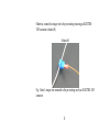
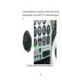
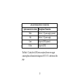
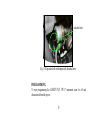
SAFETY- FLY 700 P
FLYING INSTRUMENT
FOR ULTRALIGHT AIRCRAFTS
NR.1017.2 MIT
USER MANUAL
UK
Preface
Manufacturer
Address
: MC elettronica S.r.l.
Document num:
Edition
: 101700.2
: April 2013
: Via E. fermi, 450/486
Fiesso Umbertiano (ROVIGO) - ITALY
Tel. +39 0425 754713
Fax +39 0425 741130
E-mail: info@mcelettronica
Internet: www.mcelettronica.it
- MC elettronica S.r.l. is not obliged to give notice of any further modifications to the product.
- The descriptions provided in this manual do not allow unauthorised personnel to tamper with the product
in any way.
- The guarantee on the equipment will no longer be valid if tampering should be detected.
© Copyright MC elettronica 2013
2
1. REGULATIONS AND GENERAL WARNINGS
1.1 Premise
- This manual gives all the specific information that you need for proper use of the
equipment in your possession.
- After buying the instrument, read the manual carefully and refer to it any time you
have doubts on how to use the equipment or when you have to carry out maintenance
operations.
- Keep the manual on board the aircraft or, at least, when this is not possible, keep it
in a known location that is ready at hand.
ALL RIGHTS RESERVED.
THIS MANUAL IS INTENDED FOR CUSTOMER USE ONLY. ANY THE
OTHER USE IS FORBIDDEN
3
1.2 Terms of guarantee
SAFETY-FLY 700 P is guaranteed for a period of 2 years from the date of
purchase, upon presentation of a till receipt or purchase invoice.
The guarantee does not apply in the event of:
accidental damage;
incorrect use, modifications that have not been authorised, improper installation
(or setting up);
damage caused when a non-MC elettronica equipment, which is mechanically
and electrically connected to our instruments, breaks or does not function
properly;
acts of God (lightning, floods, fire or any other causes which do not depend on
MC elettronica).
Repairs covered by the warranty (within 2 years of the date of purchase) carried out
at the workshops of our authorised centres, are fully free of charge as long as the
instrument is sent carriage free. Transport charges and risks are entirely borne by the
Customer.
4
The above-mentioned guarantee is valid unless otherwise stated between MC
elettronica and the Customer.
NOTE
!
MC elettronica declines any liability for damage or direct or indirect
charges, as a consequence of improper use or inability by the
Customer to use the equipment separately and/or together with other
instruments.
1.3 Assistance service
Service is available in all the countries where the equipment is officially supplied by
MC elettronica (during and after the guarantee period), or directly at the MC
elettronica manufacturing company.
5
1.4 General description
A
B
C
D
G
M
A
F
6
REF.
DESCRIPTION
A
FUEL indicator light to CHECK fuel circuit valves and pressure alarm
B
High cylinder head temperature alarm indicator light (CHT).
Dual-purpose indicator light; when permanently lit, it means that the motor
oil temperature is correct. When flashing it means that the timer is running,
setting off the buzzer every 2 minutes, to be used to return to position or for
various uses, such as, for example, to provide a reminder of closed valves in
flight.
C
D
MANUAL
F
G
High motor oil temperature alarm indicator light
Motor oil pressure alarm indicator light; at its maximum in flashing mode,
minimum in steady mode.
Button for several functions; it silences the buzzer, it turns on the timer, it
programmes alarm thresholds.
3-level flap indicator, T/O - ½ - FULL with timer buzzer at 1 minute, also
for programming the fuel alarm thresholds.
7
1.5 Instrument assembly
Install SAFETY-FLY 700 P where it is most comfortable for the pilot; in the
picture it is installed on the bottom right hand area of the motor instrument
dashboard.
Safety Fly 700 P
Fig. 1 SAFETY-FLY 700 P installed on the motor instrument dashboard.
8
1.6 Electrical connections
Set the connections up as shown in the table, observing the colours of the cables, and
referring to the STC 1017.1 connection board on page 24-25
8-POLE Input/Output CONNECTOR
8-pole connector wire colours
Description of connections
Orange
Input (-) cylinder head temperature CHT
Black
Input (-) Motor oil temperature
Red
Input (-) motor pressure temperature
Green
Input (-) Flaps sensor
Yellow
Input (+) fuel pressure transducer
Grey
Input R, to be brought up to +12V when the fuel transducer
is not connected to the fuel pressure instrument.
Brown
Blue
Buzzer output (-)
Buzzer output (+)
9
Example of the connection between the orange wire and the CHT cylinder head
temperature instrument,
solution A: replace the original female terminal with a new one, connecting the
orange wire to the pre-existing one
Solution A
Fig. 2 detail Orange wire connected to the CHT cylinder head temperature
instrument
10
Otherwise, connect the orange wire to the pre-existing one using an ELECTROTAP connector (solution B)
Solution B
Fig. 3 detail - orange wire connected to the pre-existing one by an ELECTRO-TAP
connector
11
Connect the supplied buzzer in a position that is possibly in front of the pilot,
observing the polarity, as set up on the STC 1017.1 connection board on page 2425
Fig. 4 Buzzer installed on the motor instrument dashboard.
12
4-POLE POWER SUPPLY CONNECTOR
4-pole connector wire colours Description of Connection
Black
Positive (+12) power supply (optional)
Red
Positive (+12) power supply
Green
Negative (GND) (optional)
Yellow
Negative (GND)
The Black (+12) and yellow (GND) wires are optional, however we suggest
connecting them as illustrated in the diagram ref. STC 1017.1 at the bottom of the
page.
13
2. PROGRAMMING
SAFETY-FLY 700 P can be programmed in two phases and in two different ways;
motor and flap alarm programming mode and fuel pressure alarm programming
mode.
2.1 PROGRAMMING MOTOR AND FLAP ALARMS.
Programming must be carried out when the motor is cold, with motor and cylinder
head oil temperature indicators below 50°C. Temporarily detach the wire for the
motor oil pressure bulb, as shown in figure 5
14
detached wire
-Fig. 5 Oil pressure bulb with temporarily detached wire
PROGRAMMING.
To start programming the SAFETY-FLY 700 P instrument must be off and
disconnected from the power.
15
2.1 PROGRAMMING MOTOR AND FLAP ALARMS.
To start programming, press the red RESET button, and hold it down (for
approximately 4 seconds) to power the instrument, releasing the button when the
first red CHT indicator light (ref. B) turns on.
Programming will now begin in a cyclical semi-automatic mode, i.e. the pilot will
interact manually with the instruments for the movement phase.
Programming starts with calibrating the cylinder head temperature alarm indicator
light (CHT), followed by the motor oil temperature (OIL TEMP), Min and Max
motor oil pressure (OIL PRESS), and display of the FLAPS.
The start and end programming sequence is shown in the table below, with the
exception of fuel pressure calibration, which is carried out in a following step using a
different mode, explained in chap. 2.2
16
During programming SAFETY-FLY 700 P generates an electric output signal
simulating the movement of the motor instrument indicators located on the
dashboard.
To store the required alarm point, press the red RESET button, and when the
indicator for the instrument is in the required position, press the key down until the
buzzer beeps 3 times, indicating that programming has been carried out correctly.
Then, release the button and continue programming the next value.
If the index relative to the instrument that requires programming moves beyond the
level requiring programming, it is possible to go back by pressing the red button a
few short times.
Continue programming all of the values, as shown in the table below.
17
Order of the
programming cycle
1st
2nd
3rd
4th
5th
6th
7th
8th
DESCRIPTION
ALARMS
Flashing red LED (ref. B) CHT Cylinder Head
Temperature
Steady green LED (ref. C) Minimum OIL temperature
Flashing red LED (ref. D) Maximum OIL temperature
Flashing red LED (ref. E) Maximum OIL pressure
Flashing red LED (ref. E) Maximum OIL pressure
1st Steady orange LED (ref. G) (T/O) FLAP
2nd Steady orange LED (ref. G) (1/2) FLAP
3rd Steady orange LED (ref. G) (FULL) FLAP
At the end of programming, turn the instrument off and reconnect the previously
detached motor oil pressure bulb wire, as shown in figure 6.
18
Reconnected wire
-Fig. 6 Reconnected oil pressure bulb wire.
If you need to re-program one or more alarms without changing the correct
thresholds, start the programming phase as described above, let the cycle run, and
only when it is necessary to re-program the new threshold, press the button
corresponding to the required value.
19
2.2 PROGRAMMING THE FUEL PRESSURE ALARM.
The fuel pressure alarm threshold must be programmed with the motor running.
When the pressure of the fuel system is considered regular, press the RED button for
approximately 7 seconds until the flashing red Fuel indicator light ref. A, and the
acoustic buzzer, come on. Next, release the button and determine the fixed 3-level
operation percentage; 7, 16, 25%.
To determine the alarm operation percentage, the 3 LED flaps (G) are used and
defined as follows: led-T/O = +/-7%, led - ½ = +/-16%, led-Full = +/-25%.
Each LED will remain lit for 5 seconds, and if in that time the red button (F) is
pressed, the corresponding percentage will be programmed.
The programmed alarm threshold, based on the voltage level that is read at the time
of calibration, and the alarm will be triggered when the voltage value drops below or
rises above the percentage value of the programmed voltage.
20
3. OPERATION.
Once SAFETY-FLY 700 P is powered, it will perform a brief test by turning on all
of the indicator lights for 2 seconds and the buzzer for 4 seconds. It is now ready for
use by controlling all levels of the inputs in Real-time if they deviate from the
programmed values.
3.1 FUEL INDICATOR LIGHT.
The FUEL indicator light carries out two distinct and different controls;
a) CHECK OPEN VALVES BEFORE TAKE-OFF.
Following the test that runs when it is switched on, as described above in point 3
and with the motor running, the FUEL indicator light (ref. A) will flash, telling
the pilot that he/she must check whether the fuel valves are open prior to takeoff.
21
If the valves are open, the indicator light and the red button will switch off (ref.
F).
b) FUEL CIRCUIT PRESSURE ALARM
When the fuel pressure falls below or rises above the value of the programmed
percentage (ref. Chapter 2.2), the Fuel indicator light will flash as the buzzer
sounds.
3.2 MOTOR ALARM OPERATION.
The CHT cylinder head temperature (ref. B) and oil temperature (ref. D) alarm
indicator lights come on when the temperatures exceed the programmed thresholds,
as well as the relative indicator light and buzzer.
The red motor oil pressure indicator light (ref. E) comes on in two different ways;
a) FLASHING - when the pressure exceeds the programmed threshold.
b) STEADY ON - when the pressure is below the programmed threshold.
22
The photo in fig.7 illustrates an example of a cylinder head temperature alarm
(CHT).
To silence the buzzer during an alarm, simply press the red RESET button (F).
3.3 GREEN INDICATOR LIGHT OPERATION.
The green indicator light (ref. C) works in two modes;
a) STEADY ON - when the motor oil temperature is correct and therefore
ready for take-off.
b) FLASHING - when the timer has been switched on from the red button.
The timer will set the buzzer off every 2 minutes for 2 seconds. To turn the
timer off simply press the button. Every time the timer is switched on, the
buzzer will sound for 2 seconds.
23
Fig. 7 example of cylinder head temperature alarm
24
3.4 FLAP LEDs.
The 3 orange FLAP LEDs (ref. G) indicate the 3 positions of the FLAPS:
a)
Flaps T/O
1 LED on steady
b)
Flaps at half-run
c)
FULL Flaps completely extended 3 LEDs on steady
2 LEDs on steady.
FLAP LEDs - TAKE-OFF PROCEDURE.
When the flaps are extended from the T/O position (one LED on), an acoustic timer
will come on where, for the first 2 minutes at 1-minute intervals, the buzzer will
sound for one second, telling the pilot that he/she must retract the flaps after take-off
to avoid them from getting damaged.
25
If, however, after 3 minutes the flaps are still extended, the buzzer will sound
continuously at regular intervals.
The same happens during landing, and should this procedure last for more than 3
minutes, the buzzer will sound continuously at regular intervals, and can be silenced
by pressing the red RESET button.
3.5 ALARM PANEL ON.
If the key is left in the dashboard with SAFETY-FLY 700 P running, the buzzer will
sound continuously after 8 seconds, reminding the pilot to turn the dashboard off,
avoiding use of current and also protecting the hour-counter.
26
IMPORTANT NOTE
We would like to specify that SAFETY-FLY 700 P is intended
to be an instrument that aids navigation, however, it in
no way replaces pilot controls. Accordingly, the pilot
must strictly observe the rules of flight and use of the
aircraft, as reported in the aircraft manual.
The pilot must always be exclusively in charge of
navigation, regardless of the installed SAFETY-FLY 700 P
instrument.
27
STC 1017.1
A
GIALLO/YELLOW
FUEL PRESSURE
B
EXISTING PLANT
FUEL PRESSURE
TRANSDUCER
ARANCIO / ORANGE
TEMP. CHT.
TEMP. CHT
SENSOR
NERO / BLACK
OIL TEMP.
OIL TEMP.
SENSOR
ROSSO / RED
PRESSION
PRESSURE
SENSOR
VERDE / GREEN
FLAPS
FLAPS
SENSOR
S
ROSSO/ RED
NERO/ BLACK
SWITCH
ON
KEY
OFF
BATTERY +12 Vdc
(input)
28
+12
(fuel)
GND
VERDE/GREEN
GIALLO/YELLOW
(R) = Do NOT connect when
the fuel transducer (A) is
connected to the fuel
pressure instrument (B)
CONNECTION SCHEME FOR SAFETY FLY 700
BUZZER
+
R
BLU / BLUE
(R) = connect to +12(fuel)
when the fuel transducer (A)
is NOT connected to the fuel
instrument (B)
12 Vdc
-
MARRONE
/ BROWN
GRIGIO
/ GRAY
(S) = switch that must be
installed on the aircraft
dashboard
29
TECHNICAL FEATURES
Power supply voltage
From 9 to 16 Vdc
Maximum absorption
150 mA @ 16 Vdc
Operating temperature
-20°C ÷ +75°C
IP Protection degree
IP55 (front) IP45 (rear)
Mechanical resistance
2g
Material
Black ABS
30
NOTES
_________________________________________________________________
_________________________________________________________________
_________________________________________________________________
_________________________________________________________________
_________________________________________________________________
_________________________________________________________________
_________________________________________________________________
31
UK
32