1
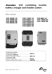
, Unit combining inverter,
battery charger and transfer system.
User manual
Common Accessories
Temperature sensor: ............................................
Accessories
:
Remote command module: ..............................
Accessories
:
Time and communication interface RTC: .........
External cooling fan: ............................................
External auxiliary relay module: ..........................
Studer Innotec SA 2012 – V4.3.0
51L
Xtender
Xtender
SUMMARY
1
2
3
4
5
6
7
INTRODUCTION.......................................................................................................................................5
GENERAL INFORMATION .......................................................................................................................5
2.1
Operating instructions .........................................................................................................................5
2.2
Conventions ..........................................................................................................................................6
2.3
Quality and warranty ...........................................................................................................................6
2.3.1 Exclusion of warranty.......................................................................................................................6
2.3.2 Exclusion of liability...........................................................................................................................7
2.4
Warnings and notes .............................................................................................................................7
2.4.1 General ..............................................................................................................................................7
2.4.2 Precautions for using the batteries ...............................................................................................8
ASSEMBLY AND INSTALLATION .............................................................................................................8
3.1
Handling and moving ..........................................................................................................................8
3.2
Storage ...................................................................................................................................................8
3.3
Unpacking..............................................................................................................................................8
3.4
Installation site .......................................................................................................................................8
3.4.1 XTM and XTH .....................................................................................................................................8
3.4.2 XTS .......................................................................................................................................................9
3.5
Fastening ................................................................................................................................................9
3.5.1 Fastening XTH model .......................................................................................................................9
3.5.2 Fastening XTM model ......................................................................................................................9
3.5.3 Fastening of the XTS model ..........................................................................................................10
3.6
Connections ........................................................................................................................................10
3.6.1 General recommendations .........................................................................................................10
3.6.2 Device connection compartment XTH - XTM...........................................................................11
3.6.3 Device connection compartment XTS ......................................................................................12
3.6.4 Elements of connection cabinet ................................................................................................13
CABLING ...............................................................................................................................................14
4.1
Choice of system ................................................................................................................................14
4.1.1 Hybrid type stand-alone systems ................................................................................................14
4.1.2 Grid-connected emergency systems ........................................................................................14
4.1.3 Integrated mobile systems ...........................................................................................................14
4.1.4 Multi-unit systems ............................................................................................................................15
4.1.5 Distributed Minigrid ........................................................................................................................15
4.2
Earthing system ...................................................................................................................................15
4.2.1 Mobile installation or installation connected to the grid via plug connector ...................15
4.2.2 Stationary installation ....................................................................................................................16
4.2.3 Installation with automatic PE-neutral switching .....................................................................16
4.2.4 Lightning protection ......................................................................................................................16
4.3
Recommendations for dimensioning the system .........................................................................16
4.3.1 Dimensioning the battery .............................................................................................................16
4.3.2 Dimensioning the inverter .............................................................................................................17
4.3.3 Dimensioning the generator ........................................................................................................17
4.3.4 Dimensioning the renewable energy sources..........................................................................17
4.4
Wiring diagrams ..................................................................................................................................17
4.5
Connecting the battery ....................................................................................................................17
4.5.1 Battery cable cross-section and DC protective devices .......................................................18
4.5.2 Connecting the battery (Xtender side) .....................................................................................18
4.5.3 Fuse mounting on battery positive pole (XTM only) ................................................................19
4.5.4 Battery-side connection ...............................................................................................................19
4.5.5 Earthing the battery ......................................................................................................................20
4.5.6 Connecting the consumers at the AC output .........................................................................20
4.5.7 Connecting the AC supply sources ...........................................................................................21
4.5.8 Wiring auxiliary contacts ...............................................................................................................21
4.5.9 Connecting the communications cables .................................................................................21
XTENDER PARAMETER SETTING ............................................................................................................22
5.1
Basic parameter setting in the XTS ..................................................................................................22
POWERING UP THE INSTALLATION .......................................................................................................22
DESCRIPTION OF THE MAIN FUNCTIONS ............................................................................................24
User manual
V4.3.0
3
Xtender
7.1
Inverter ..................................................................................................................................................24
7.1.1 Automatic load detection (load search) .................................................................................24
7.2
Transfer relay........................................................................................................................................24
7.2.1 Type of detection of AC input loss (UPS) ...................................................................................24
7.2.2 Limiting the AC input current ”Input limit”.................................................................................25
7.3
Battery charger ...................................................................................................................................26
7.3.1 Working principle ...........................................................................................................................26
7.3.2 Battery charger current setting ...................................................................................................28
7.3.3 Battery protection ..........................................................................................................................28
7.4
Xtender protection ............................................................................................................................28
7.4.1 Protection in case of overload ....................................................................................................28
7.4.2 Protection against overvoltage ..................................................................................................28
7.4.3 Protection against overheating ..................................................................................................28
7.4.4 Protection against battery reverse polarity ..............................................................................29
7.5
Auxiliary contacts ...............................................................................................................................29
7.6
The real time clock .............................................................................................................................29
7.7
Entry command (Remote control on/off) .....................................................................................29
8
MULTI-UNIT CONFIGURATION .............................................................................................................30
8.1
Three-phase system............................................................................................................................31
8.2
Increasing the power by paralleling units......................................................................................31
8.3
Combined system ..............................................................................................................................31
8.4
Enlargement of an existing installation ...........................................................................................31
9
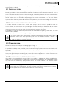
ACCESSORIES .......................................................................................................................................32
9.1
Control centre and display RCC-02/-03 (remote control) .........................................................32
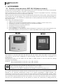
9.2
BTS-01 temperature sensor ...............................................................................................................33
9.2.1 Connecting the temperature sensor (BTS-01) ..........................................................................33
9.3
Remote control Module RCM-10 (XTM/XTS) ..................................................................................33
9.3.1 Connection of the RCM-10 module ...........................................................................................33
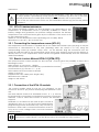
9.4
Time and communication module TCM-01(XTS) ..........................................................................34
9.5
Auxiliary Relay Module ARM-02 (XTS) .............................................................................................34
9.6
External Cooling Fan unit ECF-01 (XTS) ...........................................................................................34
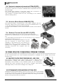
10 OTHER DEVICES COMPATIBLE XTENDER SYSTEMS..............................................................................34
10.1
BATTERY STATUS PROCESSORS BSP- 500/1200 ................................................................................34
10.2
COMMUNICATION MODULE XCOM-232I .......................................................................................34
11 CONTROL ..............................................................................................................................................35
11.1
Main on/off control ............................................................................................................................35
11.2
Display and control panel ................................................................................................................35
12 MAINTENANCE OF THE INSTALLATION ...............................................................................................37
13 PRODUCT RECYCLING .........................................................................................................................37
14 EC DECLARATION OF CONFORMITY ..................................................................................................37
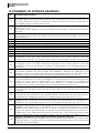
15 COMMENTS OF APPENDIX DRAWINGS ..............................................................................................38
16 DRAWING’S ELEMENTS (DC SIDE)........................................................................................................39
17 FIGURE ELEMENT'S (AC PART) ..............................................................................................................40
18 MECHANICAL DIMENSION AND MOUNTING ELEMENT .....................................................................42
19 NAMEPLATE (FIG. 1B) ...........................................................................................................................42
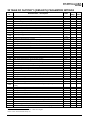
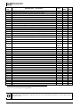
20 TABLE OF FACTORY’S (DEFAULTS) PARAMETERS SETTINGS ................................................................43
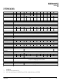
21 TECHNICAL DATA .................................................................................................................................45
22 NOTES ....................................................................................................................................................46
User manual
V4.3.0
4
Xtender
1 INTRODUCTION
Congratulations! You are about to install and use a device from the Xtender range. You have
chosen a high-tech device that will play a central role in energy saving for your electrical
installation. The Xtender has been designed to work as an inverter / charger with advanced
functions, which can be used in a completely modular way and guarantee the faultless functioning
of your energy system.
When the Xtender is connected to a generator or network, the latter directly supplies the
consumers, and the Xtender works like a battery charger and backup device if necessary. The
powerful battery charger has an exceptional high efficiency and power factor correction (PFC)
close to 1. It guarantees excellent battery charging in all situations. The charge profile is freely
configurable according to the type of battery used or the method of usage. The charge voltage is
corrected depending on the temperature, thanks to the optional external sensor. The power of the
charger is modulated in real time dependent according to the demand of the equipment
connected at the Xtender output and the power of the energy source (network or generator). It
can even temporarily backup the source if the consumer demand exceeds the source capacity.
The Xtender continuously monitors the source to which it is connected (network or generator) and
disconnects itself immediately if the source is missing, disturbed or does not correspond to the
quality criteria (voltage, frequency, etc.). It will then function in independent mode, thanks to the
integrated inverter. This inverter, which has an extremely robust design, benefits from STUDER
Innotec’s many years of experience and expertise in this area. It could supply any type of load
without faults, enjoying reserves of additional power that is unmatched on the market. All your
equipment will be perfectly provided with energy and protected from power outages in systems
where energy supply is unpredictable (unreliable network) or voluntarily limited or interrupted, such
as hybrid installations on remote sites or mobile installations.
The parallel and/or three-phase network operation of the Xtender offers modularity and flexibility
and enables optimum adaptation of your system to your energy requirements.
The RCC-02/-03 control, display and programming centre (optional) enables optimum
configuration of the system and guarantees the operator continuous control for all important
parameters in the installation.
In order to guarantee perfect commissioning and functioning of your installation, please read this
manual carefully. It contains all the necessary information relating to the functioning of the inverters
/ chargers in the Xtender series. The setting up of such a system requires special expertise and may
only be carried out by qualified personnel familiar with the applicable local regulations.
2 GENERAL INFORMATION
2.1 OPERATING INSTRUCTIONS
This manual is an integral part of each inverter/charger from the Xtender series.
It covers the following models and accessories1:
Inverter/charger:
XTH 3000-12 – XTH 5000-24 – XTH 6000-48 – XTH 8000-48
XTM 1500-12, XTM 2000-12, XTM 2400-24,
XTM 3500-24, XTM 2600-48, XTM 4000-48
XTS 900-12, XTS 1200-24, XTS 1400-48
External cooling fan: ECF-01
Temperature sensor: BTS-01
Remote command module: RCM-10
Auxiliary relay module: ARM-02
For greater clarity, the device is referred to in this manual as Xtender, unit or device, when the
description of its functioning applies indiscriminately to different Xtender models.
These operating instructions serve as a guideline for the safe and efficient usage of the Xtender.
Anyone who installs or uses an Xtender can rely completely on these operating instructions, and is
bound to observe all the safety instructions and indications contained. The installation and
commissioning of the Xtender must be entrusted to a qualified professional. The installation and
1
Also for 120Vac model (-01)
User manual
V4.3.0
5
Xtender
usage must conform to the local safety instructions and applicable standards in the country
concerned.
2.2 CONVENTIONS
This symbol is used to indicate the presence of a dangerous voltage that is sufficient to
constitute a risk of electric shock.
This symbol is used to indicate a risk of material damage.
This symbol is used to indicate information that is important or which serves to optimise your
system.
All values mentioned hereafter, followed by a parameter number indicate that this value may be
modified using the RCC-02/-03 remote control.
In general, the default values are not mentioned and are replaced by a parameter number in the
following format: {xxxx}. The default values for this parameter are specified in the defaults
parameter table, p.43.
All parameter values modified by the operator or installer must be transferred into the
same table. If a parameter not appearing in the list (advanced parameters) has been
modified by an authorised person with technical knowledge, they will indicate the number
of the modified parameter(s), the specifications of the parameter(s) and the new value
set, at the end of the same table.
All figures and letters indicated in brackets or in square brackets refer to items that can be found in
the separate manual “Appendix to the installation and operating instructions” supplied with the
device. In this appendix, these figures and letters are encircled.
The figures in brackets refer to elements belonging to the Xtender.
The uppercase letters in brackets refer to AC cabling elements.
The lowercase letters in brackets refer to battery cabling elements.
The comments on figures and items of figures of the appendix are given p. 39 and following.
2.3 QUALITY AND WARRANTY
During the production and assembly of the Xtender, each unit undergoes several checks and tests.
These are carried out with strict adherence to the established procedures. Each Xtender has a
serial number allowing complete follow-up on the checks, according to the particular data for
each device. For this reason it is very important never to remove the type plate (appendix 1 – fig.
3b) which shows the serial number. The manufacture, assembly and tests for each Xtender are
carried out in their entirety by our factory in Sion (CH). The warranty for this equipment depends
upon the strict application of the instructions appearing in this manual.
2.3.1 Exclusion of warranty
No warranty claims will be accepted for damage resulting from handling, usage or processing that
does not explicitly appear in this manual. Cases of damage arising from the following causes are
notably excluded from the warranty:
Surge voltage on the battery input (for example, 48 V on the battery input of an XTH 300012)
Incorrect polarity of the battery
The accidental ingress of liquids into the device or oxidation resulting from condensation
Damage resulting from falls or mechanical shocks
Modifications carried out without the explicit authorisation of Studer Innotec
Nuts or screws that have not been tightened sufficiently during the installation or
maintenance
Damage due to atmospheric surge voltage (lightning)
Damage due to inappropriate transportation or packaging
Disappearance of original marking elements
User manual
V4.3.0
6
Xtender
2.3.2 Exclusion of liability
The placement, commissioning, use, maintenance and servicing of the Xtender cannot be the
subject of monitoring by Studer Innotec. For this reasons we assume no responsibility and liability for
damage, costs or losses resulting from an installation that does not conform to the instructions,
defective functioning or deficient maintenance. The use of a Studer Innotec inverter is the
responsibility of the customer in all cases.
Studer Innotec shall in no event be liable for consequential, incidental, contingent or special
damages, even if having been advised of the probability of such damages. This equipment is
neither designed nor guaranteed to supply installations used for vital medical care nor any other
critical installation carrying significant potential damage risks to people or the environment.
Studer Innotec assumes no responsibility for the infringement of patent rights or other rights of third
parties that result from using the inverter.
Studer Innotec reserves the right to make any modifications to the product without prior
notification.
2.4 WARNINGS AND NOTES
2.4.1 General
This manual is an integral part of the device and must be kept available for the operator
and installer. It must remain close to the installation so that it may be consulted at any
time.
The parameter table available at the end of the manual (p. 43) must be kept up to date in the
event of modification of the parameters by the operator or installer. The person in charge of
installation and commissioning must be wholly familiar with the precautionary measures and the
local applicable regulations.
When the Xtender is running, it generates voltage that can be potentially lethal. Work on
or close to the installation must only be carried out by thoroughly trained and qualified
personnel. Do not attempt to carry out ongoing maintenance of this product yourself. The
Xtender or the generator connected to it may start up automatically under certain
predetermined conditions.
When working on the electrical installation, it is important to be certain that the source of
DC voltage coming from the battery as well as the source of AC voltage coming from a
generator or network have been disconnected from the electrical installation.
Even when the Xtender has been disconnected from the supply sources (AC and DC), a
dangerous voltage may remain at the outputs. To eliminate this risk you must switch the
Xtender OFF using the ON/OFF button (1). After 10 seconds the electronics is discharged
and intervention may take place without any danger.
All elements connected to the Xtender must comply with the applicable laws and regulations.
Persons not holding written authorisation from Studer Innotec are not permitted to proceed with
any change, modification or repairs that may be required. Only original parts may be used for
authorised modifications or replacements.
This manual contains important safety information. Read the safety and working instructions
carefully before using the Xtender. Adhere to all the warnings given on the device as well as in the
manual, by following all the instructions with regard to operation and use.
The Xtender except XTS, is only designed for indoor use and must under no circumstances be
subjected to rain, snow or other humid or dusty conditions. The maximum specifications of the
device shown on the type plate, as at fig. 1b, must be adhered to.
In the event of use in motorised vehicles, the Xtender must be protected from dust, splash water
and any other humid condition. It must also be protected from vibration by installing absorbent
parts.
User manual
V4.3.0
7
Xtender
2.4.2 Precautions for using the batteries
Lead-acid or gel batteries produce a highly explosive gas with normal use. No source of
sparks or fire should be present in the immediate vicinity of the batteries. The batteries
must be kept in a well-ventilated place and be installed in such a way as to avoid
accidental short-circuits when connecting.
Never try to charge frozen batteries.
When working with the batteries, a second person must be present in order to lend
assistance in the event of problems.
Sufficient fresh water and soap must be kept to hand to allow adequate and immediate
washing of the skin or eyes affected by accidental contact with the acid.
In the event of accidental contact of the eyes with acid, they must be washed carefully
with cold water for 15 minutes. Then immediately consult a doctor.
Battery acid can be neutralised with baking soda. A sufficient quantity of baking soda
must be available for this purpose.
Particular care is required when working close to the batteries with metal tools. Tools such
as screwdrivers, open-ended spanners, etc. may cause short-circuits. Consequently
occurring sparks may cause the battery to explode.
When working with the batteries, all metal jewellery such as rings, bracelet watches,
earrings, etc., must be taken off. The current output by the batteries during short-circuit is
sufficiently powerful to melt the metal and cause severe burns.
In all cases, the instructions of the battery manufacturer must be followed carefully.
3 ASSEMBLY AND INSTALLATION
3.1 HANDLING AND MOVING
The weight of the Xtender is can be up to 50kg depending upon the model. Use an appropriate
lifting method as well as help from a third party when installing the equipment.
3.2 STORAGE
The equipment must be stored in a dry environment at an ambient temperature of between
-20°C and 60°C. It stays in the location where it is to be used a minimum of 24 hours before being set up.
3.3 UNPACKING
When unpacking, check that the equipment has not been damaged during transportation and
that all accessories listed below are present. Any fault must be indicated immediately to the
product distributor or the contact given at the back of this manual.
Check the packaging and the Xtender carefully.
Standard accessories:
Installation and operating instructions, c.f. Appendix 1
Mounting plate for XTH and XTS– fig. 2a (25)(26)
One set of cable glands on the unit and/or apart.
Four M6 screws and washer for XTS to assemble the support and the enclosure.
3.4 INSTALLATION SITE
3.4.1 XTM and XTH
Devices in the XTM and XTH range are designed for indoor use (IP20) and the place of installation
must satisfy the following criteria:
Protected from any unauthorised person.
Protected from water and dust and in a place with no condensation.
It must not be situated directly above the battery or in a cabinet with it.
No easily inflammable material should be placed directly underneath or close to the
Xtender.
Ventilation apertures must always remain clear and be at least 20cm from any obstacle
that may affect the ventilation of the equipment.
In mobile applications it is important to select an installation site that ensures as low a
vibration level as possible.
User manual
V4.3.0
8
Xtender
3.4.2 XTS
XTS range appliances have a high grade of protection (IP54). They can therefore be installed
outdoors, with exposure to dust and water splashes. It is recommended to avoid places particularly
exposed to salt water splashes which are extremely aggressive (for instance under a vehicle
chassis) or to solvent (motor oil) that can attack all non-metallic parts of the enclosure. Also avoid
installing the XTS in direct sunlight or near a heat source (i.e. engine compartment). The presence of
a heat source may reduce significantly the nominal power of the unit.
Reduce as much as possible exposure to sudden temperature changes as a variation in
temperature may cause undesired condensation inside the enclosure.
The 4 mounting screws of the enclosure must be completely tightened with a tightening
torque of 5Nm in order to guarantee the IP 54 protection index. Any unused cable
glands should be closed in a way that guarantees at least the same level of protection.
3.5 FASTENING
The Xtender is a heavy unit and must be mounted to a non-flammable support (wall)
designed to bear such a load
The Xtender must be installed vertically onto heavy duty material (concrete or metallic wall) and
positioned vertically with cable glands oriented down. A sufficient space around it must be
provided to guarantee adequate ventilation of the device (see figs. 2a).
3.5.1 Fastening XTH model
First fix the mounting bracket (26)) supplied with the device using 2 Ø < 6-8 mm >screws**.
Then hang the Xtender on the bracket. Fasten the unit permanently using 2 Ø <6-8 mm> screws**
on to the two notches located at the underside of the case.
Dimensions of the appliances are given on Fig 2a of the appendix 1
A minimum distance of 20 cm in between and/or around the XTH devices is required in
order to guarantee sufficient ventilation.
3.5.2 Fastening XTM model
Screw first the top screw (6-8mm **) without washer on a solid wall (concrete or metallic wall) up to
a distance of 2mm between head and wall. Hang the apparatus by taking care to release
beforehand the trap door of access (27 fig. 2a of the appendix) by inserting it inside the apparatus
using a screwdriver, if you estimate that a complete tightening of this point of fixing is necessary. In
theory complete tightening is necessary only in the mobile installations.
Dismount the lower plastic cap of the apparatus giving access to the compartment of wiring.
Carefully fix the apparatus with two screws (Ø 6-8 mm) in the two clamp holes down inside the
compartment of wiring.
If the Xtender is installed in a closed cabinet this must have sufficient ventilation to guarantee an
ambient temperature that conforms to the operation of the Xtender.
**: These items are not delivered with the device.
It is imperative to ensure complete and safe fastening of the device. A device that is
simply hung may detach and cause severe damage.
User manual
V4.3.0
9
Xtender
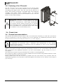
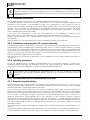
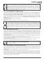
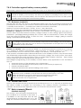
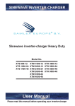
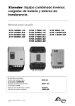
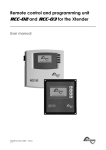
3.5.3 Fastening of the XTS model
The XTS enclosure must be first mounted on the support plate
with the 4 screws and washer delivered with the appliance
according with figure aside. Then the unit can be fixed on a
heavy duty support (concrete or metallic wall) and positioned
vertically with cable glands oriented down. An external
ventilation unit (ECF-01 p. 34 ) can be installed on top of the unit
before or after wall mounting.
The envelope of the XTS can reach temperature higher
than 60°C when used for a long period at the maximum of its performances. These high temperatures
may remain present during several tens of minutes
after stopping the unit. It’s recommended to choose a
place of installation in a restricted access area, away
from children or any unauthorized person.
3.6 CONNECTIONS
3.6.1 General recommendations
The Xtender falls within protection class I (has a PE connection terminal). It is vital that a protective
earth is connected to the AC IN and/or AC OUT PE terminals. An additional protective earth is
located at the bottom of the unit (See sect 3.6.4 – p. 11/12, tag (17)).
In all cases, the PE conductor for the equipment must at least be connected to the PE for
all equipment in protection class I upstream and downstream of the Xtender
(equipotential bonding). It is mandatory that the legislation in force for the application
concerned be adhered to.
Tighten of the input (13) and output (14) terminals by means of a no. 3 screwdriver and those for
the “Command entry (REMOTE ON/OFF”) (7) and “AUX.CONTAC” (8) by means of a no. 1
screwdriver.
The cable cross-sections of these terminals must conform to local regulations.
All connection cables as well as the battery cables must be mounted using cable restraints in order
to avoid any traction on the connection.
Battery cables must also be as short as possible and the cross-section must conform with the
applicable regulations and standards. Sufficiently tighten the clamps on the “battery” inputs (fig. 4a
(11) and (12)).
User manual
V4.3.0
10
Xtender
3.6.2 Device connection compartment XTH - XTM
The unit’s connection compartment must remain permanently closed when in operation.
It is imperative to close the protection cap on the connection terminals after each
intervention in the device.
After opening, check that all sources of AC and DC voltage (batteries) have been
disconnected or put out of service.
Some accessible part inside the compartment can have surface temperature higher
than 60°C. Wait for the complete cooling of the unit before opening the compartment.
Any unused cable entry on the device must be sealed so as to prevent any intrusion. An
intrusion of small animals in the unit may cause serious damage not covered by warranty.
User manual
V4.3.0
11
Xtender
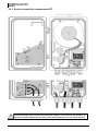
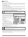
3.6.3 Device connection compartment XTS
Any unused cable entry on the device must be sealed so as to prevent any intrusion. An
intrusion of small animals in the unit may cause serious damage not covered by warranty.
User manual
V4.3.0
12
Xtender
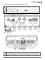
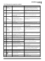
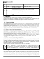
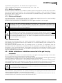
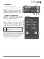
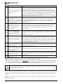
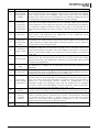
3.6.4 Elements of connection cabinet
Pos. Denomination Description
Comment
Main on/off switch
1
ON/OFF
Main switch
2
Temp. Sens
Connector for the battery
temperature sensor
4
O/T
(Open /
Terminated)
5
--
6
--
Double connector for
connecting peripherals such as
the RCC-02/03 or other
Xtender units
Switch for terminating the
communication bus.
Set position (open) if the 2
connectors (3) are occupied.
Set position T if only one is
occupied.
3.3 V (CR-2032) lithium ion type
battery socket
Jumper for programming the
off/on switch by dry contact
7
Command
entry
(REMOTE
ON/OFF)
Entry command terminals..
In XTM series, this entry is
deported on the remote
command module RCM-10.
See sect. 9.3 – p. 33
8
AUXILLARY
CONTACT
9
--
10
L1/L2/L3
11
+BAT
12
-BAT
13
AC Input
14
AC Output
15
RCM-10
16
I-CHAR
3
Com. Bus
17
18
INPUT LIMIT
User manual
Auxiliary contact
For XTS model, available only
with module ARM-02 (see sect.
9.5 - p. 34
Activation indicators for
auxiliary contacts 1 and 2
Phase selection jumpers.
Positive pole battery
connection terminals
Negative pole battery
connection terminals
Connection terminals for the
alternative power supply
(generator or public network)
Connection terminals for the
device output.
Connector for RCM-10 module
Rotating knob to adjust the
battery charge current
Connection for supplementary
protective earth.
Rotating knob to adjust the
input current limit
V4.3.0
See sect. 11.1 – p. 35.
In XTM and XTS series, this function is
deported on the remote command
module RCM-10. See sect. 9.3 – p. 33
See sect. 9.2 – p. 33.
Only connect the original Studer BTS-01
sensor
For the XTS model, these connectors are
available only if the module TCM-01 (see
sect. 9.4 – p. 34) is implemented.
On model XTH the 2 termination switches
(4) must be in the same position: Or the
2 in position O (open) or the 2 in position
T (terminated)
Used as a permanent supply for the
internal clock. See sect. 7.6 - p. 29
See sect. 7.7 – p. 29 and fig. 8b point (6)
and (7). They are positioned at A-1/2 and
B-2/3 by default
Allow to dive a function – to be defined
by programming – by the closing of a dry
contact or by the presence of a voltage
across these terminals. See sect. 7.7 – p.
29).
(See sect. 7.5 – p. 29)
Take care not to exceed the admissible
loads
See sect. 7.5 – p. 29
See sect. 8.1. – p. 31.
Jumper default at position L1
Carefully read sect. 4.5 – p.17
Take care with the polarity of the battery
and when tightening the clamp.
See sect. 4.5.7 - p. 21.
Note: It is imperative that the PE terminal
be connected.
See sect. 4.5.6 - p. 21.
Note: Increased voltages may appear
on the terminals, even in the absence of
voltage at the input of the inverter.
Only on XTM. See sect. 9.3 – p. 33
Only in XTS model.
This connection can also be used as
principal protective earth. See sect.
3.6.1– p. 10.
Only in XTS model. For other models, see
sect. 7.2.2 – p. 25
13
Xtender
19
OFF/ON
S/Boost
20
OFF/ON
UPS
21
16A
Activation of source assistance Only in XTS model. For other models, see
“Smart boost” function
sect. 7.2.2.4 – p. 26
Setting of sensitivity of the
Only in XTS model. For other models, see
detection of AC input loss:
section. 7.2.1 – p. 24
OFF=tolerant / ON=Fast
AC input protective device: Only on XTS model. This protective device will
trip in case of excessive load when the XTS is connected to an
unprotected source higher than 16A.
It can be reset after removing the default downstream (load too high) and
upstream (source greater than 16A. (check the unit is connected thru an
upstream protective device (fuse or circuit breaker) max. 16 A
Insertion holes for TCM-01 optional communication module (see sect. 9.3.1
- p. 33
4 CABLING
The connection of the Xtender inverter / charger is an important installation step.
It may only be carried out by qualified personnel and in accordance with the applicable local
regulations and standards. The installation must always comply with these standards.
Pay attention that connections are completely tightened and that each wire is connected at the
right place.
4.1 CHOICE OF SYSTEM
The Xtender may be used in different system types, each of which must meet the standards and
particular requirements associated with the application or site of installation. Only an appropriately
qualified installer can advise you effectively on the applicable standards with regard to the various
systems and the country concerned.
Examples of cabling are presented in appendix I of this manual, fig. 5 and following. Please
carefully read the notes associated with these examples in the tables on p. 33 and following.
4.1.1 Hybrid type stand-alone systems
The Xtender can be used as a primary supply system for off- grid sites where a renewable energy
source (solar or hydraulic) is generally available and a generator is used as backup. In this case,
batteries are generally recharged by a supply source such as solar modules, wind power or small
hydropower systems. These supply sources must have their own voltage and/or current regulation
system and are connected directly to the battery. (Example, fig. 11)
When the energy supply is insufficient, a generator is used as a back-up energy source. This allows
the batteries to be recharged and direct supply to consumers via the Xtender transfer relay.
4.1.2 Grid-connected emergency systems
The Xtender can be used as an emergency system, also known as an uninterruptible power supply
(UPS) – enabling a reliable supply to a site connected to an unreliable network. In the event of an
interruption to the energy supply from the public network, the Xtender, connected to a battery,
substitutes the faulty source and enables a support supply to the users connected downstream.
These will be supplied as long as the energy stored in the battery allows. The battery will quickly be
recharged at the next reconnection to the public grid.
Various application examples are described in figs. 8a – 8c in appendix 1.
The use of the Xtender as a UPS must be carried out by qualified personnel who have
been checked by the responsible local authorities. The diagrams in the appendix are
given for information and as a supplement. The applicable local standards and
regulations must be adhered to.
4.1.3 Integrated mobile systems
These systems are meant to be temporarily connected to the grid and ensure the supply of the
mobile system when this is disconnected from the grid. The main applications are for boats, service
vehicles and leisure vehicles. In these cases, two separate AC inputs are often required, one
connected to the grid and the other connected to an on-board generator. Switching between
two sources must be carried out using an automatic or manual reversing switch, conforming to the
User manual
V4.3.0
14
Xtender
applicable local regulations. The Xtender has a single AC input.
Various application examples are described in figs. 10a – 10b – 10c.
4.1.4 Multi-unit systems
Whatever system is selected, it is possible to realise systems composed of several units of the same
type and the same power output. Up to three Xtenders in parallel or three extenders forming a
three-phase grid or three times two or three Xtenders in parallel forming a three-phase / parallel
grid, may be thus combined.
4.1.5 Distributed Minigrid
The implementation of the Xtender on top of a distributed minigrid (beyond the main building)
requires special care in choosing the distribution system.
Studer Innotec recommends a TT distribution for the DC grid as well as for the AC grid.
The size of the grid increases greatly the exposure of the inverters to atmospheric
overvoltages and to non equipotentiality in the grid. This is particularly noticeable in the
aerial distribution grids. In this case a very special care must be taken to well implementing
all protection measures of the installation.
The IT system is not recommended for the distribution. This kind of distribution is most of the
time forbidden by the local laws. The achievement of low voltage electric system is always
subject to local laws and must imperatively be implemented and controlled by qualified
and professionally authorized staff. Studer Innotec accepts no liability for damages due to
non-confirming installation and to the lack of compliance with the local rules or with the
recommendations of this manual.
4.2 EARTHING SYSTEM
The Xtender is a protection class I unit, which is intended for cabling in a grid type TT, TN-S or TNC-S.
The earthing of the neutral conductor (E) is carried out at a sole installation point, upstream of the
RCD circuit breaker (D).
The Xtender can be operated with any earthing system. In all cases it is imperative that the
protective earth be connected in compliance with the applicable standards and regulations. The
information, notes, recommendations and diagram mentioned in this manual are subject to local
installation regulations in every case. The installer is responsible for the conformity of the installation
with the applicable local standards.
4.2.1 Mobile installation or installation connected to the grid via plug
connector
When the input of the device is connected directly to the grid via a plug, the length of the cable
must not exceed 2 m and the plug must remain accessible.
In the absence of voltage at the input, the neutral and live are interrupted, thereby guaranteeing
complete isolation and protection of the cabling upstream of the Xtender.
The earthing system downstream of the Xtender is determined by the upstream earthing system
when the grid is present. In the absence of the grid, the earthing system downstream of the inverter
is in isolated mode. The safety of the installation is guaranteed by the equipotential bonding.
The connection (link) between the neutrals (C) upstream and downstream of the Xtender
is not permitted in this configuration.
This connection type guarantees the optimal continuity for supplying the Xtender loads. The first
isolation fault will not lead to an interruption in the supply.
If the installation requires the use of a permanent isolation controller this would have to be deactivated when the TT network is present at the Xtender input.
User manual
V4.3.0
15
Xtender
All sockets and protection class I devices connected downstream of the Xtender must be
properly connected to the earth (earthed socket). The cabling rules above remain valid,
including in installations, in all cases where the Xtender input is connected to the grid via a
plug connector.
4.2.2 Stationary installation
The installation may be equivalent to a mobile installation (with interrupted neutral).
In a fixed installation where the neutral is connected to the earth at a single installation point
upstream of the Xtender, it is permissible to carry out a connection of the neutrals in order to
preserve an unchanged earthing system downstream, independent of the operating mode of the
Xtender. This choice has the advantage of keeping the protection devices downstream of the
Xtender. This connection can be executed according to the examples in appendix 1, or carried
out by modifying the parameter {1486}
In this case the appearance of the first fault will lead to the installation stopping or the
disconnection of the protection devices upstream and/or downstream of the Xtender.
Safety is guaranteed by the equipotential bonding and by any RCD circuit-breakers placed
downstream.
This connection (C) is not permitted if a socket is installed upstream of the Xtender.
4.2.3 Installation with automatic PE-neutral switching
In certain applications, it is desirable to keep the neutral upstream and downstream of the Xtender
separated (C) while re-establishing the earthing system (TN-S, TT or TNC-S) in the absence of voltage
at the input. This functionality is forbidden by default by the parameter {1485}. This parameter can
be modified by the parameter {1485} via the RCC-02/-03 remote control. This modification must be
carried out possessing technical knowledge, at the responsibility of the installer and in conformity
with the applicable regulations and standards.
The authorization of this function adherence to the requirements for an earth-neutral connection at
the source.
4.2.4 Lightning protection
As per the installation site, it is highly recommended to set a protection strategy to protect your
installation against lightning. The strategies depend on various parameters directly linked to each
site and we recommend therefore to deal very professionally with this issue.
The damages due to lightning are generating most of the time significant costs (full
replacing of the printed electronic board) and are not covered by Studer Innotec’s
warranty.
4.3 RECOMMENDATIONS FOR DIMENSIONING THE SYSTEM
4.3.1 Dimensioning the battery
The battery capacity is dimensioned according to the requirements of the user – that is 5 to 10
times its average daily consumption. The discharge depth of the battery will therefore be limited
and the service life of the battery will be extended.
On the other hand, the Xtender must have a battery capacity that is large enough to be able to
take full advantage of the performance of the equipment. The minimum capacity of the batteries
(expressed in Ah) is generally dimensioned in the following way: five times the rated power output
of the Xtender / the battery voltage. For example, the model XTH 8048 must have a battery of a
minimum capacity of 7000*5/48=730 Ah (C 10). Because of the inverter’s extreme overload
capacity, it is often recommended that this value be rounded up. An under-dimensioned battery
may lead to an accidental and undesired stopping of the Xtender in the event of high instances of
use. This stoppage will be due to a voltage that is insufficient on the battery, subject to a strong
discharge current.
The battery will be selected with regard to the greatest value resulting from the calculations set out
above.
The battery capacity determines the adjustment of the parameter {1137} “battery charge current”.
A value between 0.1 and 0.2 x C batt. [Ah] (C10) enables an optimum charge to be guaranteed.
User manual
V4.3.0
16
Xtender
The method proposed below is strictly indicative and in no way constitutes a guarantee of
perfect dimensioning. The installer is solely responsible for good dimensioning and
installation
4.3.2 Dimensioning the inverter
The inverter is dimensioned in such a way that the rated power output covers the power of all the
consumers which will be used at the same time. A dimensioning margin of 20 to 30% is
recommended to guarantee that the Xtender will work well in an ambient temperature of more
than 25 °C.
4.3.3 Dimensioning the generator
The power output of the generator must be the same or more than the average daily power.
Optimally, it should be two or three times this power. Thanks to the input limit function (see sect.
7.2.2 - p. 25) it is not necessary to over-dimension the generator. Indeed, the loads those are
temporarily higher than the power of the generator will be supplied by the inverter.
Ideally the generator should not have a power output by phase that is less than half of the power
of the Xtender(s) present at this phase.
The power available downstream of the inverter when the generator is working is the
same as the sum of the two powers if the Smart Boost function is activated. The sum of the
currents is limited to a maximum of 57A (80A for the models XTH 8000-48, XTH 6000-48-01,
and XTH 5000-24-01). This sum is limited to 20A in XTS model
4.3.4 Dimensioning the renewable energy sources
In a hybrid system, the alternative energy sources such as the solar generator, wind power and
small hydropower should, in principle, be dimensioned in such a way as to be able to cover the
average daily consumption.
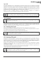
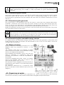
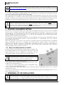
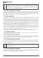
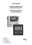
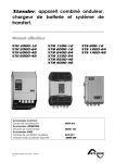
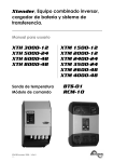
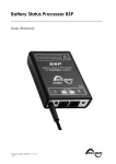
4.4 WIRING DIAGRAMS
Several schematics and wiring comments as in the
diagram aside are proposed in Annex I of this
manual.
The diagram aside gives an example of hybrid
system for remote site with some renewable energy
sources and single phase generator.
These diagrams are indicative, and in any case the
wiring is subsidiary to compliance with local
standards and practices, under the responsibility of
the installer.
Comments regarding the letters / and / or numbers
cited in the diagram aside and of those in the
appendix are given in sect. 16 to 19.
The elements of these diagrams are referenced by a
capital letter when relates to the alternating current
(AC) elements.
The elements referenced by a lowercase letter
relates to the direct current elements (DC part of the
diagram.)
4.5 CONNECTING THE BATTERY
The terminals of dc input / output of the apparatus (11) - (12) p. 9 are intended to be exclusively
connected to a battery, usually of lead acid batteries with gelled or liquid electrolyte
User manual
V4.3.0
17
Xtender
The use of the Xtender connected to any other type of DC source without battery (buffer)
is strictly prohibited and not cause significant damage to the device and / or at source
The use of other battery type like Ni-Cd, Li-Ion or other is possible subject to a proper setting of load
profile in accordance with the specifications of the manufacturer of the battery and under the
responsibility of the installer
Each Xtender is connected directly to the battery through its own protective device (fuse
or circuit breaker. It should never be connected to the output of a DC voltage regulator
like solar regulator, without having the battery as buffer.
All other consumers or sources are connected directly to the battery by their own
protective devices. (See details (f) on Fig. 11-18)
Lead batteries are usually available in 2 V, 6 V or 12 V block types. In the majority of cases, in order
to obtain an operating voltage that is correct for Xtender usage, several batteries must be
connected in series or in parallel depending on the circumstances.
In multi-unit systems, all Xtenders from the same system must be connected according to
the same battery bank.
The various cabling options are presented in figures 5a-5b (12 V), 5c-5e (24 V) and 6a to 6d (48 V) in
appendix I of this manual.
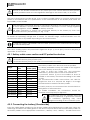
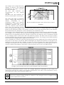
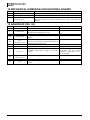
4.5.1 Battery cable cross-section and DC protective devices
The battery cables must be protected by one of the following measures in all cases:
- protection device (fuse) at each pole
- protection device (fuse) on the pole not connected to the earth
XTS-900-12
XTS 1200-24
Battery
fuse
100A
80A
Cable crosssection (<3m)
25mm2
25mm2
XTS-1400-48
50A
16mm2
XTM-4000-48
200A
50mm2
XTM-2600-48
100A
25mm2
XTM-3500-24
300A
70mm2
XTM-2400-24
200A
50mm2
XTM-2000-12
300A
70mm2
XTM-1500-12
XTH-8000-48
XTH-6000-48
XTH-5000-24
XTH-3000-12
250A
300A
300A
300A
350A
70mm2
95mm2
70mm2
95mm2
95mm2
Range
The battery cables must also be as short as possible.
It is always preferable to keep the cable at the negative
pole of the battery as short as possible.
In order to avoid any further loss and protection
redundancy, the XTH does not have an internal fuse.
A protective device (f) must be installed as close as
possible to the battery and sized according to the table
on side.
The recommended cable cross-sections are valid for
lengths less than 3 m. beyond this length it is strongly
recommended oversize the battery cables.
For safety reasons, we recommend an annual check on
the tightness of all connections.
For mobile installation the connections should be
checked more frequently for tightness.
The cable lugs must be carefully fixed and
tightened sufficiently to guarantee minimum
loss. Insufficient tightening may cause
dangerous heating at the connection point.
4.5.2 Connecting the battery (Xtender side)
Insert the cable glands supplied on the battery cable before tightening the cable lugs. Crimp the
cable lugs and fasten the cable gland on the device. Repeat this for the second battery cable. Fix
the battery cables to the appropriate connections „+ Battery “and „- Battery “. The M8 screws must
User manual
V4.3.0
18
Xtender
be very well tightened.
On XTM range, you can insert, if required, a fuse directly on the positive connection to the battery
following the below procedure.
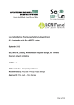
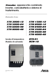
4.5.3 Fuse mounting on battery positive pole (XTM only)
A fuse delivered with the unit (XTM) can be mounted directly on the positive connecting pole to
the battery respecting the below stacking order.
The XTS is equipped with an electronic protection device protecting it from accidental
reversal of polarity of the battery. This does not exempt of installing a protective device
close to the battery
The presence of this fuse does not exempt an installation of a protective device (fuse or circuit
breaker) as close as possible of the battery.
a = M10 cable lug!!
b = bolt M8 x 30
c = washer
d = ceramic washer
e = fusible
Be careful with the orientation of the ceramic washer. There is a small lip on one side
which must fit into the M10 cable lug’s hole.
4.5.4 Battery-side connection
Before connecting the battery, carefully check the voltage and polarity of the battery
using a voltmeter.
Incorrect polarity or over- voltage may seriously damage the device.
Prepare the batteries for connection: appropriate battery clamps, protection device (f), cable in
good conditions with correctly fitted clamps.
Fasten the negative cable on to the negative pole (-) of the battery and the positive cable on the
open protection device (f).
When connecting the battery, a spark may occur when connecting the second pole. This
spark is normal and due to the load of the internal filtering capacity of the Xtender even if
the unit is halted by the main on off command (1).
As of the connection of the battery, it is necessary to check that the parameter values of
the Xtender are consistent with the recommendations of the battery manufacturer. Nonconforming values may be dangerous and/or seriously damage the batteries.
The default values of the battery’s charge threshold level are shown in fig. 3a and specified in the
parameter table p.43. If they are not acceptable when compared to the battery manufacturer’s
specification,, it is necessary to modify them via the RCC 02/03 remote control before connecting
the voltage sources on the AC input (charger). Studer Innotec is not responsible for default values
not corresponding with the recommendations of the manufacturer.
If the factory settings are modified, the new values must be entered on the parameter table on p.
43 of this manual. The default values proposed by Studer Innotec are the usual values for lead acid
User manual
V4.3.0
19
Xtender
battery or gel batteries (VRLA or AGM).
The cabling and connection of the installation should only be carried out by an appropriately
qualified professional. The installation material such as cables, connectors, distribution boxes, fuses,
etc. must be adapted and must conform to the applicable laws and regulations the application
under consideration.
4.5.5 Earthing the battery
One of the two battery conductors can be earthed. This may be either the positive or negative
pole. In all cases the installation must conform to the local regulations and usage or specific
standards associated with the application.
In case of earthing, the earthing conductor cross-section must at least be equivalent to the crosssection of the battery conductor. The earthing of the equipment must also adhere to these
regulations. In this case the use of the additional earthing screw is recommended ((17) p. 11/12,
which is located at the front of the device between the two lower fastening screws.
4.5.6 Connecting the consumers at the AC output
High voltages may be present on the connection terminals (13) and (14). Make sure that
the inverter is deactivated and that there is no AC or DC voltage present on the AC IN
terminals and battery terminals, before proceeding with the connection.
The 230 V consumers must be connected on
the “AC OUT” (14) connection terminals with
the wire cross-section conforming to the
standards with regard to the rated current at
the Xtender output (see fig. 1a). Distribution
must conform to the local standards and
regulations, and generally, be realised via a
distribution table.
The Xtender terminals are marked in the
following way:
N = neutral, L = live
= protective earth (connected to the
enclosure of the device).
On the model XTS remove the cover plate by
unscrewing the three screws (A figure below) to
access the input/output AC terminals (13-14) and
protective earth (15).
A
A
4.5.6.1
Sizing of AC output protective
devices:
If protective devices are installed at the
A
output, we recommend B curve devices.
They will be sized at maximum to the highest
the value listed on the unit’s nameplate at
point (37) (Fig. 1a of the Appendix) or by the
addition of the first value plus the value of
the input protective device. (i.e. inverter
current + input current).
Cross-sections of downstream wiring must be sized accordingly
No downstream protective device is formally required if cross-sections of cable used for
distribution satisfy regulatory requirements for the largest rated output current listed on the
nameplate at the point (37) of Appendix 1a.
If the source assistance function (Smart Boost)(see sect. 7.2.2– p. 25 is not used; the size of the
protection device for the output (F) will be established at a maximum value equal to the rated
current of the inverter, or at the maximum value of the protection device at the input (H) if that one
exceeds the rated current of the inverter.
If the AC input (13) is not used the protective device will be sized equal or smaller than the smaller
value indicated on the nameplate on tag (37)
User manual
V4.3.0
20
Xtender
Due to the source assistance function (Smart Boost) the current at the output of the
device may be higher than the rated current of the inverter. It is the sum of the current
supplied by the additional source and the current supplied by the inverter. In this case, the
dimensioning of the output cables will be carried out by adding the current indicated on
the protection device (H) located on the upstream of the unit, to the nominal current of
the inverter. (See fig. 1a and chap. 7.2.2.4 – p. 26)
4.5.7 Connecting the AC supply sources
The Xtender is intended to be supplied by alternative voltage sources such as the public grid or a
generator. Check that the rated voltage of the source corresponds to the rated voltage (34) of the
Xtender specified on the nameplate (fig. 1b)tag(34).
The source must be connected to the input terminals marked “AC INPUT” (13) with sufficient wire
cross-section, depending on the power output of the source, and protected by a protection
device of the appropriate calibre. This will be at the maximum 50A for XTH and XTM range and 16A
for XTS appliances.
The terminals are marked in the following way:
N = neutral, L = live
= protective earth (connected to the enclosure of the device).
An additional earthing terminal (17) is present between the two fastening screws at the
bottom of the unit. It can be used instead of a connection on the input terminals of the
device, particularly when cable cross-sections used at the output do not allow the use of
a three-wire cable (live, earth and neutral) through the conduit glands of the connection
cables of the input and output (AC IN and AC OUT), or when the earthing of one of the
poles of the battery. PE required using same or greater cross-sections than the battery
cable.
4.5.8 Wiring auxiliary contacts
These contacts are reversing contacts that are potential-free available in XTH and XTM units. On XTS
models, these auxiliary contacts are available on the external auxiliary relay module (accessory)
ARM-02 (see sect. 9.5 – p. 34). The admissible currents and voltages for these contacts are 16 A: 250
VAC/24VDC or 3 A: 50 VDC max. The Contact is shown as activated when the corresponding LED is
lit. The representation of the contact near the terminals corresponds to the status of the contact
when not activated.
The cabling of these auxiliary contracts depends solely on the chosen application and on the
specific programming applied and cannot be described in this manual.
To dedicate/program particular functions to these contacts, please refer to user manual of the
remote control unit RCC-02/03
The factory-set functions for these 2 auxiliary contacts are covered in the sect. 7.5 – p. 29.
Any unused cable gland on the unit must be properly closed.
If not, there is a high risk of intrusion of small animals inside the unit and a risk of damage
not covered by warranty
4.5.9 Connecting the communications cables
The Xtenders with built-in TCM-01 accessory are equipped with a pair of RJ45/8 connectors that
allow information transfer via a communication bus for different consumer types which have the
proprietary protocol of Studer Innotec. In this network all parties in the network are connected in
series (chain).
The length of the communication bus cable must not exceed 300 m.
When the Xtender is connected to the remote control RCC-02/-03 or another Xtender compatible
device (VarioTrack, BSP etc.) it is possible that their software versions differ. It is important to
harmonize the software versions of all Xtender compatible products in a system. The update is
made by the remote control RCC-02/-03 from an SD card with a firmware version at least
corresponding to the most recent device.
User manual
V4.3.0
21
Xtender
At the commissioning it is essential to have the last version of firmware available on the site
http://www.studer-innotec.com These files should be copied to the SD card delivered with
the remote control RCC-02/-03.
In a system comprising a single Xtender, the connection of the RCC-02 or RCC-03 may be
conducted without stopping the Xtender (hot plug).
The communication bus will be used to interconnect other Xtender inverters in the case of a multiunit application or to connect other types of users who have the proprietary protocol of Studer
Innotec. In these cases, the plug-in of interconnected units is done only after the switch-off of the
installation, by disconnecting the battery or by using the main “ON/OFF” button (1) if present.
The 2 switches for the communication bus termination, “Com. Bus" (4) both remain in
position T (terminated) except when both connectors are in use. In this case, and only in
this case, both must be placed in the O open position. If one of the two connectors is not
in use, the two termination switches (14) will be in position T.
5 XTENDER PARAMETER SETTING
All inverters of the Xtender family have many factory settings and some of them can be modified
by the user or installer. Some basic parameters mentioned in Chapter 7 must be set at the
commissioning. For models XTM and XTH, this setting must be done by connecting the remote
control described in RCC-02/03 chap. 7.3.1 - p. 36. For the model XTS four of them can be done
directly into the unit before powering up.
Many features and associated parameters not described in this manual are described further in
the manual accompanying remote control RCC-02/03 or downloaded from the website
www.studer-innotec.com.
When the Xtender is connected to the remote control RCC-02/-03 or another Xtender compatible
device (VarioTrack, BSP etc.) it is possible that their software versions differ. It is important to
harmonize the software versions of all Xtender compatible products in a system. The update is
made by the remote control RCC-02/-03 from an SD card with a firmware version at least
corresponding to the most recent device.
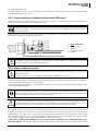
5.1 BASIC PARAMETER SETTING IN THE XTS
For XTS models, the 4 parameters / basic functions below can
be modified directly in the compartment inside the door. All
other parameters can be adjusted, if necessary, via the
remote RCC-02/03 and communication module TCM-01.
Before opening the enclosure, it is mandatory to
disconnect all AC and DC sources (battery) of the
product to avoid any risk of electrical shock.
These 4 parameters can be set as below:
• The battery current charge {1138} as described chap. 7.3.2 p. 28 by the potentiometer (16)
• The max. AC source (input limit) {1107} as described chap.
7.2.2 - p. 25 by the potentiometer (18)
• The source current assistance (Smart boost) function {1126} as described chap.7.2.2.1 - p. 25 by
the slide button (19)
• The type of detection of AC-input loss (UPS) Fast/Tolerant/slow {1552} as described chap. 7.2.1- p.
24 by the slide button (20)
6 POWERING UP THE INSTALLATION
It is imperative that the closing cap for the connection compartment (XTM and XTH) and
the XTS enclosure is correctly installed and screwed tight before turning on the power.
There are dangerous voltages within the interior of the connection compartment.
User manual
V4.3.0
22
Xtender
Attention: only a complete tightening of all 4 mounting screws of the XTS enclosure
guarantees the IP 54 protection index.
The Power up of the Xtender must be carried out in the order given below. Any Power off must be
carried out in the reverse order.
6.1.1.1
Connecting the battery
A too high or inappropriate battery voltage may seriously damage the Xtender. For
example, installing a 24 V battery in the Xtender 3000-12.
If the Xtender XTH or XTM) has been connected the wrong way around by accident
(incorrect polarity of the battery) it is highly likely that the protection fuse on the battery
cable may melt and will have to be replaced. If such is the case, it will be necessary to
disconnect all the connections to the Xtender including the battery. If, after replacing the
fuse, the Xtender proves not to work correctly after reconnecting the battery with the
correct polarity, it will have to be returned to your distributor for repair.
The XTS is electronically protected against reverse polarity. In case of reverse polarity
connection, the unit will remain off. No alarm will signal the fault. It will operate normally
after recovery of the correct polarity.
6.1.1.2 Putting the Xtender(s) in operation using the main ON/OFF switch (1) if present
The Xtender is supplied and is ready for operation. If you require immediate start-up of the inverter
when the battery is powered up, the main switch (1) must be in the “ON” position and the
parameter {1111} activated. If special configurations or settings are required by the system, it is
recommended to do so immediately according to sect. 5 - p. 22
6.1.1.3 Connecting the consumers at the output
Activate the output protection device (F) if existing, and/or press the ON/OFF button (41). The light
indicator “AC out” (46) lights up or flashes (in the event of an absence of consumers).
6.1.1.4 Activating the input circuit breaker(s) (H)
If an AC source (generator or electrical grid) valid in frequency and voltage is present at the AC
input, the device automatically goes into transfer and will start to charge the batteries. The
consumers at the output are therefore supplied directly by the power source present at the input.
Your installation is now in operation.
User manual
V4.3.0
23
Xtender
7 DESCRIPTION OF THE MAIN FUNCTIONS
7.1 INVERTER
The Xtender is equipped with a high-performance inverter which supplies a perfect and very
precise sine wave. Any unit designed for the 230 V/50 Hz electrical grid (or 120V/60Hz for model XTxxxxx-01) may connect to it without any problem, up to the rated power out of your Xtender. The
inverter is protected against overloads and short-circuits.
Thanks to the largely over-dimensioned performance level, loads of up to three times greater than
the Xtender’s rated output can be faultlessly supplied for short (3 sec) periods of use, thus allowing
motors to be started up without any problem.
When the Xtender is operating the LED “ON” (43) is glowing.
When the Xtender is in inverter mode, the LED “AC out” (46) is glowing. If it flashes, the inverter is in
“load search” mode (see following sect. “Automatic load detection”).
7.1.1 Automatic load detection (load search)
In order to save battery energy, the Xtender inverter stops and automatically goes into load search
mode when the detected load is lower than the sensitivity set by the parameter {1187}. It
automatically goes back into operation when a power consumer greater than this value demands
it. The indicator (46) flashes if the inverter is in “load search” mode, which also indicates that the AC
voltage is present at the output in an intermittent form.
The detection threshold for the absence of loads can be adjusted according to the parameter
range {1187} by means of the RCC-02/-03 remote control. When the parameter is set to 0 the
inverter will still operate even in the absence of any consumer.
In load search mode (standby) the system will thus consume minimal power from the battery (see
table of technical data p.45).
7.2 TRANSFER RELAY
The Xtender can be connected to an alternative power source such as a generator or public
network. When the voltage at the entry satisfies the voltage {1199 + 1470} and frequency {1505 1506} parameters, the transfer relay will be activated after a delay {1528}. This delay may be
adjusted (extended) to allow a fully stable status of the generator before transfer.
When the transfer relay is activated, the voltage present at the input of the Xtender is available at
the output for the consumers connected. At the same time the battery charger goes into
operation.
When the transfer relay of the Xtender is active, the voltage at the output of the Xtender is
equivalent to that which is present at the input and cannot be influenced or improved by
the Xtender. The consumers are supplied by the source present at the “AC IN” input via
the transfer relay.
The maximum current of the transfer relay is 50 A for XTH and XTM model. It is of 16A in XTS model.
The sharing of energy between consumers and the battery charger is adjusted automatically (see
sect.7.2.2– p.25). The transfer relay will be deactivated when the input voltage no longer satisfies
the parameter {1199} or {1432} min. and max. voltage and frequency at the input or when the
current limit {1107} is exceeded, if the exceeding of this limit is prohibited {1436}. It then passes
immediately into inverter mode. In this case the loads are supplied exclusively by the battery via
the inverter (see sect. 7.2.2.4 – p.26. This switching always takes place automatically.
The presence of increased dynamic loads (such as pneumatic angle grinders, etc.) may lead to an
undesirable opening of the transfer relay due to the weakness of the source. To this case, a delay in
the opening of the transfer relay can be adjusted with the parameter {1198}.
When the generator stops, the change from transfer mode to inverter mode normally takes place
without any interruption of the output voltage. The interruption will be 20 ms in case of input voltage
sudden disappearing when the type of detection of input loss (UPS) {1552} is selected to “tolerant”.
7.2.1 Type of detection of AC input loss (UPS)
When the Xtender is connected to the public grid or to a generator supplying stable and clean AC
voltage, the type of detection of input loss {1552} can be selected to “fast”. In this mode,
perturbation or lack of voltage of less than 1 millisecond can be detected, switching the unit in
User manual
V4.3.0
24
Xtender
inverter mode immediately.. This mode guarantees a zero or maximum of 15 ms transfer time
This mode should not be used in presence of highly disturbed utility grid or with a low power
generator or a generator supplying a poor quality voltage. In that case the parameter {1552} will
be set on “tolerant”. In the XTS model, this can be selected by positioning the UPS slide switch (20)
in “off” position. The tolerance of this mode is adjustable with the parameter {1510} if required.
The ”tolerant” UPS mode insure a interruption time of max. 20 milliseconds.
In rare cases, due to the low quality of the source, and if the transfer relay switches too frequently,
it is possible to further reduce the sensitivity of detection AC input loss of by changing the
parameter {1552} to "slow" via remote control RCC-02/03. In this case, the interruption of power will
be 40 ms max.
If the Xtender is connected to a generator, this must have a power at least equal to half
of the power of the Xtender(s) to which it is connected.
7.2.2 Limiting the AC input current ”Input limit”
7.2.2.1 Principle
In order to best use the resources available at the input (depending on the generator size or the
grid output) and to protect the source from overload, it’s possible to adjust the limit of the input
current with the parameter {1107}.
The Xtender will automatically distribute the available power to the charger and the user and
supply the balance of power if the load demand exceeds the fixed limit thanks to the current
assistance function so called “smart boost”.
Due to the current assistance feature, the battery can be fully discharged despite the
presence of the grid or the generator! The average power consumed by the user must
not exceed the power of the source, at the risk of discharging the battery.
This system proves to be a decisive advantage particularly in all mobile systems (boats, leisure
vehicles and service vehicles) that are frequently connected to sources with a limited value such
as a portable or camping power supply. Despite a limited source, all the greater power
applications downstream of the Xtender remain functional.
Despite a limited source, all loads connected downstream the Xtender remain functional!
The system will reduce automatically the charging current– from its target value {1138} to 0 –
according to the current used at the output and the maximum current available at the input set by
the parameter {1107}. The greater the current at the output, the more the part of the current at the
input assigned to charging the battery is reduced. If the current exceeds the limit {1107}, the
Xtender will supply the balance current from the battery.
The wiring of the system (cable gauge) must take into account this particular function which allow
to have the sum of the current supplied by the inverter plus the current supplied by the source,
I.e. If the system have a 5kW source (22A) and a 5 kW Xtender, the available power at the output is
10kW! In this example, the wire gauge must be chosen for 45A.
7.2.2.2 Exceeding input limit current
If, despite the decrease in current from the charger and using the source current assistance the
limit is exceeded, the transfer relay will remain activated and the source may then be overloaded,
causing the opening of the protective device upstream (H).
Exceeding the limit may be prohibited by the parameter {1436}. In this case, if the current exceeds
the limit {1107}, the transfer relay will open and the user then powered exclusively by the inverter, as
long as the output current exceeds the current limit input. If the input current limit is exceeded due
to a short circuit downstream, the transfer relay will remain activated and the protective device
upstream of the Xtender (H) will trip.
7.2.2.3 Second value of input current limit
A second value of the input limit, to be activated by the command entry (see sect. 7.7 - p. 29, is
programmable by the parameters {1566} (Use a different value for the maximum current of the AC
source) and {1567} (Second maximum current of the AC source).
User manual
V4.3.0
25
Xtender
In the case of mobile applications the installation of an RCC-02/-03 remote control is
recommended, in order to be able to adapt the value of the input current limit if
necessary, for each connection to a limited grid.
7.2.2.4 Deactivation of the source assistance function (Smart Boost)
This feature the source current assistance (smart boost” can be disabled by setting {1126).
The remote RCC-02/03 is necessary to disable the function on the model XTH and XTM. On the XTS
model it is possible to disable it by selecting the slide button (19) in OFF position.
7.2.2.5 Automatic reduction of the current limit input
When the device is connected to a low power generator, most often, the voltage of the generator
falls down before its rated power. To compensate partially this side effect, the Xtender has a system
of automatic reduction of the input current limit, if the voltage drops beyond a threshold set by the
parameter {1309}+ {1433 }, to fall to zero when it reaches the value set by parameter {1309}. This
avoids overloading the generator and too frequent transition of the transfer relay.
This feature is also used when a variable power sources is connected to the input of the Xtender.
This is particularly the case of 230Vac alternators type "Dynawatt" coupled to drive motors whose
speed varies. These devices have their source voltage decrease depending on the available
power. A correct setting of thresholds {1309} and {1433} ensures continuous power output with the
"Smart Boost"
This feature can be disabled by setting the {1527} especially when the Xtender is connected to a
public network.
7.2.2.6 Setting the current "Input limit"
The maximum input current can be adjusted by the knob (18) on the XTS or via remote control
RCC-02/03 on other models or on the XTS with the module TCM-01. The parameter {1107} is part of
the basic parameters of the device and must be adjusted at commissioning (see sect. 5 - p. 22)
depending on the capacity of the source as follows:
• If the device is connected to a network: the value is sized according to the upstream protective
device (fuse or circuit breaker) or a lower value if desired.
• If the device connected to a generator, the following empirical formula can be used:
Generator power below 1 kW: 0.7 x Pnom / Uac
Generator power below 3 kW: 0.8 x Pnom / Uac
Generator power above 3 kW: 0.9 x Pnom / Uac
Given the wide divergence of performance and quality of available generators on the market,
these formulas are approximate and are not a guarantee of proper adjustment of the installation.
7.3 BATTERY CHARGER
7.3.1 Working principle
The battery charger for the Xtender is completely automatic and is designed in such a way as to
guarantee an optimum charge for the majority of the lead-acid or gel batteries. Once the transfer
relay is activated, the battery charger goes into operation and the charge indicator (44) lights up.
The charging process is at 3 levels (I/U/Uo) as described in figure below.
this process guarantees optimum charging of the batteries. The charging current is given by the
parameter {1138} and can be adjusted continuously from 0 to the nominal value with the help of
the RCC-02/-03 or with the rotating knob (16) inside the model XTS (see sect. 5.1 – p. 22). All times
and threshold can be adjusted with the remote control unit RCC-02/03.
If the battery voltage is lower than the critical disconnection threshold {1488} operation of
the charger will be automatically prevented. Only the transfer relay is authorised to
operate in this case. The battery must then be recharged by an external source up to a
voltage higher than the critical disconnection threshold in order to allow the Xtender
charger to operate.
User manual
V4.3.0
26
Xtender
The charge cycle, programmed by
default, as shown in the example
described in the figure opposite,
runs automatically.
The
line
(28)
indicates
the
development
of
the
battery
voltage.
The lower line (29) indicates the
battery current (input and output).
ACin=OK
28
{1138}
{1156}
{1140}
{1159}
29
a
e
d
The cycle starts with a continuous
current charge (a) adjusted by
default
according
to
the
parameter {1138}. If the ambient
Fig. 3b: Simplified charge cycle, without input current
temperature is increased or the
limitation
ventilation blocked, the current
may be reduced and become
lower than the selected current.
Once the absorption voltage {1156) is reached, the cycle passes to voltage adjustment mode (d),
known as the absorption phase, the duration of which is set by the parameter {1157}. The minimum
interval between two absorption cycles is limited by the parameter {1161).
At the expiry of the absorption time, or if the absorption current is lower than the parameter {1159},
the voltage is set to a lower value {1140}. This phase (e) is known as the maintenance or “floating”
phase. Due to the limiting function for the input current (see the above p. 25), it is perfectly normal
for the charge current to be lower than the selected current if the limit of the AC input current
{1107} is reached (b). In this event the AC IN indicator (45) flashes. The charge current will be limited
too if the battery voltage ripple is higher than 0,5V/cell.
If the “Smart Boost” function is activated {1126} and the power required by the consumer exceeds
the power of the source, the battery will be discharged (c) despite the presence of the grid or the
generator. In this case the LED “charge” (4) goes out. The consumers must ensure that they have
average consumption that is less than the power of the source (generator or public grid) in order to
avoid a complete discharge of the battery. These situations are set out in the figure below.
Charge cycle example with input current limitation and “Smart Boost”
If the BTS-01 temperature sensor is used, the voltage adjustment thresholds for the battery are
corrected in real time by means of the battery temperature. The value of this correction is set by
the parameter {1139} in the parameter table p. 43.
Much more complex charge profiles or exclusion of the charger can be configured using
the RCC-03/03 remote control.
User manual
V4.3.0
27
Xtender
Parameters of the battery charger are under the responsibility of the operator. Incorrect
parameter that does not correspond to the charging methods of the battery
recommended by the manufacturer may be dangerous and/or considerably diminish
the battery service life. If the factory settings are modified, it is imperative that the new
values be entered in the parameter table p. 43.
7.3.2 Battery charger current setting
The maximum charging current can be adjusted by the knob (16) on the XTS or via remote control
RCC-02/03 on the other models or on the XTS with the module TCM-01. The parameter {1138} is part
of the basic parameters of the device and must be adjusted at commissioning (see chap. 5 - p. 22)
depending on battery capacity. It will be chosen in principle a value between 0.1 and 0.2 x the
nominal battery capacity C10. (I.e. 10A for a battery of 100 Ah/C10)
7.3.3 Battery protection
The battery is protected against deep discharge by stopping the inverter if the low voltage
disconnection level {1108} is reached. The indicator (52) flashes once when the battery has
reached the disconnection threshold and the inverter will stop shortly after {1190}. This threshold
can be dynamically corrected {1191} with an advanced algorithm that computes automatically
the battery voltage compensation in function of the instantaneous power. This correction may also
be manually fixed {1532} by setting the low voltage disconnection at full load {1109}. These
dynamic corrections can be deactivated by setting the parameter {1191}. The inverter will stop
immediately if a critically voltage of 1.5V/cell is reached. The inverter will restart automatically
when the battery voltage has reached the restarting threshold {1110}.
This restarting threshold {1110} can be automatically readjusted if the parameter {1194} is activated,
in order to better protect the battery against repeated cycling in an "almost empty" state of
charge. The restarting threshold is then incremented {1298} up to a maximum value {1195},
whenever the LVD (low voltage disconnection) is reached. The restarting threshold will be reset to
its initial value when the value of parameter {1307} is reached.
If the inverter is repeatedly {1304} encountering a low voltage disconnection in a short period
{1404}, it will stop permanently and will only start again via an operator’s manual restart.
7.4 XTENDER
PROTECTION
The Xtender is protected electronically against overloads, short-circuit, overheating and reverse
current (cabling of a voltage source on AC out).
7.4.1 Protection in case of overload
In the event of overload or short-circuit at the output, the inverter stops for some seconds {1533}
{1400}, and restarts. If the inverter is repeatedly encountering this situation {1300} in a short period, it
will stop permanently and will only start again via an operator’s manual control.
7.4.2 Protection against overvoltage
If the battery voltage exceeds the value set by the parameter {1121} the inverter stops and starts
up again when the voltage is less than {1110}. If the Xtender is repeatedly encountering this
situation 3 times during one minute, it will stop permanently and will only start up again via an
operator’s manual control.
A battery voltage greater than 1.66 x the nominal voltage may lead to significant damage
or destroy the device.
7.4.3 Protection against overheating
Insufficient ventilation, increased ambient temperature or obstructed ventilation may lead to
overheating of certain internal components of the unit. In this case, the device will automatically
limit its power output as long as this abnormal situation persists.
User manual
V4.3.0
28
Xtender
7.4.4 Protection against battery reverse polarity
The Xtender is protected from reverse polarity by means of an external fuse installed on the battery.
The XTS is equipped with a full electronic protection device protecting it from accidental
reversal of polarity of the battery. This does not exempt by installing a fuse close to the
battery. In case of reverse polarity, the fuse will not be destroyed and the unit will operate
normally after restoring the correct battery polarity
7.5 AUXILIARY CONTACTS
The XTH, XTM and XTS, with TCM-01 and ARM-02 module, have two dry reversing contacts that are
potential-free. The status of the contacts in deactivated mode is indicated by the annotations, N.C.
= normally closed and N.O. = normally open. When the contact is activated
Maximum contact loads: 230 Vac / 24 Vdc: 16 A or: max. 50Vdc/ 3A
These dry contacts are programmed by default for the following functions:
Contact no. 1 (AUX 1): The contact has a function of automatic start of generator (two wires). The
contact will be activated when the battery voltage is below a value, during a given time fixed by
parameters {1247/48}/{1250/51}/{1253/54} The contact will be deactivated or when the charge
cycle has reached floating {1516}, or when the "Aux. 1 deactivation voltage" {1255} is reached
during a predetermined time {1256}
The voltage of the battery is automatically compensated according to the instantaneous
battery current the same way as it is done for compensation of LVD (see sect. 7.3.3– p.28)
if parameter {1191} is activated.
Contact no. 2 (AUX2) : alarm contact by default. It is deactivated when the inverter is out of service
or is working at reduced performance, either because of manual control or if there is an
operational fault such as overload, under-voltage of the battery, over-temperature, etc.
If the operator or installer requires different behaviour for the auxiliary contacts, they are both freely
and individually programmable depending on the battery voltage, the output power, the inverter
status, the internal clock and the Battery state of charge (if BSP module is present) . These setting
can be done with the RCC-02/-03 (remote control unit)
The intelligent programming of the auxiliary contacts allows many applications to be considered
such as:
Automatic start-up of the generator (two or three wires)
Automatic load shedding of lower priority loads of the inverter (2 sequences)
Global or individual alarm
Automatic disconnection (load shedding) of the source
For more information on the auxiliary contacts nr 1 and 2 programming, do refer to our
application notes available on Studer web site: www.studer-innotec.com. Like:
AN003: Anti-blackout system for grid connected application (Solsafe)
AN005: Automatic management of 2 different energy sources
AN007 Automatic start of a generator
7.6 THE REAL TIME CLOCK
The XTH, XTM and the XTS with optional TCM-01 module (see sect. 9.4 – p. 34) have a real time clock
that allows notably to program the functioning of the auxiliary contacts according to time
schedule. This clock must be adjusted via the use of the RCC-02/-03 remote control.
7.7 ENTRY COMMAND (REMOTE
CONTROL ON/OFF)
This function and associated terminal block
(7) is available as a standard on XTH series. It
is available on the series XTM and XTS with
optional TCM-01 module (see sect. 9.4– p. 34)
using the external module RCM-10 in option.
User manual
V4.3.0
29
Xtender
See sect. 9.3 - p. 33.
This entry can be used to drive one or more function that you can choose thru programming with
the RCC-02/-03.
There is no dedicated function from factory. In multi-unit configuration (see below) the chosen
functionality must be the same in every unit in the system. Only one unit can be wired to apply the
function to every Xtender in the system. If the entry command is used as an emergency stop, (all
functions halted), it has to be wired on the unit with the highest serial number (master) of phase
one.
The function is activated, or by opening /closing a potential free contact, or by applying a voltage
on the entry.
On XTH model, the wiring is done across the entry terminal block (7). The jumpers (6) must be
correctly positioned according to the chosen variant as described in the figure opposite.
Driving by a dry contact: the jumpers are
left in original factory setting A1-2 and
Main ON/OFF (only with
6
B2-3
dry contact)
6p
Driving by a voltage (Max. 60 V
Command entry with
1
eff./30mA): the jumper are positioned
dry contact
A+-B1 and A2-B2
6
+
On XTM and XTS + TCM-01, the wiring of
Command entry with
_
6p
this entry is done on the RCM-10 plug
external DC source.
1
according to the wiring example on the
(Max. 60V d.c / 60 mA)
6
figure aside, or wired thru the external
Entry command by
module RCM-10 according to sect.9.3–
6p
external AC source.
p. 33.
1
(Max. 60 V a.c./ 60 mA)
8 MULTI-UNIT CONFIGURATION
Several Xtenders can be used in the same system, either to create a three-phase system or to
increase the power output of a single or two phases. The implementation of this configuration
requires particular precautions and it must be installed and commissioned by qualified personal
only.
When multi-unit system is commissioned, the software's version of every unit will be
automatically checked and units may refuse to start in case of incompatibility. If so, an
upgrade of every units is be required with the RCC-02/-03 and the last software version
available by the manufacturer. (Read the RCC-02 user's manual to perform this operation).
In Multi-units system every Xtender in the system shares the same battery bank.
Separate battery bank are no allowed
In these multi-unit systems, the units must be interconnected via a communication bus connected
to the connectors (3) by a cable (art. no. CAB-RJ45-8-2) of a maximum length of 5 metres. The XTS
model must be equipped with TCM-01 to be used in multi-units configuration.
Various application examples are described from fig. 12 to fig. 19 of Appendix 1.
It is important to read and adhere to the descriptions associated with each of the figures
mentioned above
In multi-unit system, it is recommended to use the automatic LVD dynamic compensation.
See parameter {1532}
In configuration with several Xtenders, each unit is controlled independently using the ON/OFF push
User manual
V4.3.0
30
Xtender
button (41). When the on/off control is given via the RCC-02/-03 remote control, it is applied
simultaneously to all units.
8.1 THREE-PHASE SYSTEM
Three Xtenders of the same voltage (power or type can be different) can be used and combined
in order to establish a three-phase grid. An example of cabling in three-phase is given at figs. 13.-14
of the appendix.
When 3 Xtenders are wired to form a three-phase grid, the wired phases at the input determine the
jumper position for selecting the phase (10). It is vital to determine and select the phase for each
Xtender. If the grid is not available at the input of the master unit (phase 1), all the units of the
system will switch to inverter mode. If only a single-phase source is available, it must be connected
to phase 1. The other two phases will therefore be supplied by the other two working units in inverter
mode.
8.2 INCREASING THE POWER BY PARALLELING UNITS
Up to three Xtenders of same type - power and voltage- can be wired in parallel in order to
increase the system’s rated power output. In this configuration, all the ACin inputs of the Xtender
must be wired. The most recent unit (according to the serial number) in the phase will act as the
master and will decide on the operation or suspension of the units in parallel according to the
consumer’s power demand. The yield of the installation is therefore still optimal.
It is possible to deactivate the master/slave mode with the parameter {1547}. In that case, the load
search mode is disabled.
An example of parallel connection is given in fig.12 Appendix 1 and the comments on p.38.
If the current of the source (per phase) is greater than 50A (XTH and XTM) or 16A (XTS), a
protective device max. 50A, respectively 16A must be installed on each of the 2 or 3
devices connected to the same phase. If the power source is limited to 50A, respectively
16A, only one device is common enough.
8.3 COMBINED SYSTEM
It is possible to combine a three-phase system with one or several phases made up of 2 or 3
Xtenders in parallel. An example of cabling is given at fig. 15.
A combination of more than one inverter on only one (or two) phase is also possible. for example,
it’s possible to build up one powerful phase for the most single phase consumer and the 2 other
phases with only one Xtender each for the 3 phase (motor) application as in the example Fig 15
Appendix I
It is therefore possible to combine up to nine Xtenders by running three Xtenders in parallel in a
three-phase grid. Examples of cabling are given in figs. 16 to 18 Appendix 1 and the comments on
p. 38.
8.4 ENLARGEMENT OF AN EXISTING INSTALLATION
Only subject to compatibility, it is most of the time possible to enlarge an existing installation by
adding one or several inverters in parallel or in a three phase configuration. The compatibility of the
new units must be checked by giving Studer Innotec the serial numbers of the inverters in the
existing installation.
The inverters belonging to the same system must be equipped with the same software
version. Take care to download the latest software version from manufacturer’s website
and do update all units of the system before the commissioning.
User manual
V4.3.0
31
Xtender
9 ACCESSORIES
9.1 CONTROL CENTRE AND DISPLAY RCC-02/-03 (REMOTE CONTROL)
An RCC-02/-03 remote display and programming unit can be optionally connected to the Xtender
via one of the two RJ45-8-type “Com. Bus” (3) connectors.
These connectors may only be used for connecting a CAN-ST compatible accessory, excluding
any other connection such as LAN, Ethernet, ISDN, etc.
The RCC-02/-03 control centre is vital for modifying the parameters of the system. Many parameters
and features are not described in this manual. The manual for the RCC-01/03 (downloadable on
www.studer-innotec.com) describes in detail each of these parameters and the context in which
they can be used.
It also allows the following functions:
Display of function synopsis
Display of the measured operational values (current / voltage / power output, etc.)
Updating of software or implementation of customised software
upload/download of inverter parameter
Updating of inverter parameters
Events logging of error message
Data acquisition of Xtender and other participants connected to the communication bus
like the BSP (Battery status processor) or / and compatible solar charge controller
The features of the RCC-02 and the RCC-03 are the same. They only differ in their external
appearance. The RCC-02 is designed for wall mounting, whereas the RCC-03 is designed as a
board device.
The RCC-03 model must be taken off the table to allow access to the SD card slot (during
updating, for example).
Model N°: RCC-02: Dimensions: H x W x D / / 170 x 168 x 43.5mm
RCC-03: Dimensions: H x W x D / / 130 x 120 x 42.2mm
The two remote control models are delivered with a 2 m cable.
Cables of specific lengths (5 m, 20 m and 50 m) can be ordered.
The article no. is as follows: CAB-RJ45-xx. The length in metres is specified as xx
Up to 3 RCC-02/-03 remote controls can be connected in series on the communication bus of one
Xtender or an Xtender multi-inverter system. In a system comprising a single Xtender, the
connection of the RCC-02 or RCC-03 may be done without stopping the Xtender (warm). When
connecting an RCC-02/-03 remote control in a multi-unit system, it is recommended that all units in
the system be stopped (disconnected from battery or by the main ON/OFF switch (1) if present)
and that the communication bus on the device on which the connection is being made be
User manual
V4.3.0
32
Xtender
terminated.
The switch (2 for XTH) for the communication bus termination, “Com. Bus" (4) remains (both
for XTH) in position T (terminated) except when both connectors (3) are in use. In this case,
and only in this case, the switch (both for XTH) must be placed in the O open position.
If one of the two connectors is not in use, the termination switches (4) (two for XTH) will be
in position T.
9.2 BTS-01 TEMPERATURE SENSOR
The optimal operating voltages for lead batteries vary depending on the
temperature. A temperature sensor is optionally available to correct the
battery voltage and guarantee an optimum charge whatever the battery
temperature. The correction factor given by the correction of the sensor is set
by the parameter {1139}
Article no. for the temperature sensor (including a 3 m cable): BTS-01.
Dimensions: H x W x D / / 58 x 51.5 x 22 mm.
9.2.1 Connecting the temperature sensor (BTS-01)
The temperature sensor, BTS-01 is supplied with a 3 m cable fitted with RJ11/6-type plugs. It may be
connected or disconnected at any time (including when the device is in use) using the
corresponding socket (2) marked “Temp. Sens.” on the Xtender. Plug the connectors into the
socket (2) until they click in. The temperature sensor sleeve may simply be stuck onto the battery or
directly next to it. The temperature sensor will be recognised automatically and the correction
made immediately.
9.3 REMOTE CONTROL MODULE RCM-10 (XTM/XTS)
The optional remote control module for XTM and XTS + TCM-01 gives the possibility to have the 2
following function:
Main ON/OFF (1) see sect.11.1 below.
This operation can only be controlled by a potential free contact.
Command entry (7) see sect. 7.7 – p. 29.
This module can be mounted on DIN rail
Article n°: RCM-10
Supplied with a 5m cable (max. length 10m).
Dimensions: 45 x 78mmH
Height on rail: 40mm
.
9.3.1 Connection of the RCM-10 module
The control module MCM-10 can be "hot plugged” on the
connector ”RCM-10" (15) without interrupting the operation of the
unit.
The main ON/OFF function as described in Sect. 11.1 - p. 35 may
be obtained by connecting a potential free contact (1) between
terminals 1 and 2. When this contact is closed, the Xtender is
stopped.
Terminals 3 to 6 of RCM-10 are used as input control as
described in Sect. 9.3- p.33. The function dedicated by
programming can be activated or by a dry contact (7)
between 5 and 6 with a connection between 3 and 4,
or by an AC or DC voltage of 60 V rms max. between
terminal 4 and 5.
The function “main ON/OFF” can be driven only by a potential free (dry) contact.
User manual
V4.3.0
33
Xtender
9.4 TIME AND COMMUNICATION MODULE TCM-01(XTS)
This module lets you connect the XTS to the remote control RCC-02/03,
as well as to other XTS or devices available and compa-tible with the
Xtender range.
The module also features a real time clock and connectors to
connect the ARM-02, RCM-10 and BTS-01 modules.
The module is mounted inside the XTS, according to the manual
delivered allong with it.
9.5 AUXILIARY RELAY MODULE ARM-02 (XTS)
This external module, connected by a 5m cable supplied with the
accessory, allows XTS to have auxiliary contacts as described sect. 7.5
- p. 29. This module can be mounted on DIN rail.
It requires the installation of the communication module TCM-01 inside
the XTS
9.6 EXTERNAL COOLING FAN UNIT ECF-01 (XTS)
The External cooling fan unit ECF-01 is an optional accessory.
It improves the performance of the device (see technical data p.
57).
It is particularly recommended to use this accessory if the ambient
temperature is high (> 40 ° C).
This unit has a of protection degree IP 54 and
can be exposed to water spray without
damage. It will however be not exposed to
splash dirty water to prevent mud or similar
particles from clogging the mechanism. The
assembly instructions are supplied with the
accessory
10 OTHER DEVICES COMPATIBLE XTENDER SYSTEMS
The devices listed below are compatible and can be part of a system Xtender and interconnected
by the communication bus. Their complete description is available on our website www.studerinnotec.com
10.1 BATTERY STATUS PROCESSORS BSP- 500/1200
This module is delivered with a 500 or 1200 A shunt. It allows current
measurement, voltage and battery temperature. It computes the
information and provides to the Xtender system all the information
derived from these measures, like the state of charge, time before
discharge, history of the state of charge over 5 days etc.
10.2 COMMUNICATION MODULE XCOM-232I
This RS232 module isolated allows access to most of the values and settings
of devices connected to the Xtender communication bus. It also features
an SD card for the acquisition of measured data, the setting of units and
historic event generated by the devices.
User manual
V4.3.0
34
Xtender
11 CONTROL
11.1 MAIN ON/OFF CONTROL
This switch (1) interrupts the electronic supply
and all the Xtender peripherals. The residual
consumption on the battery is therefore less than
1 mA.
The ON/OFF switch is used only for the complete
stoppage of the whole system. This switch is not
available in the XTM. The function can be added
with the use of the remote command module
RCM-10.
11.2 DISPLAY AND CONTROL PANEL
The Xtender has a ON/OFF button and light
indicators at the front of the unit, allowing clear
identification of the operating mode.
(41) The ON/OFF button allows the start-up or
complete stop of the system. In the systems
comprising several units, each unit is started or
stopped individually. For a simultaneous start-up of
all the units use the dry contact control (see
sect. 7.7 – p. 29) or the ON/OFF button of the RCC02/-03 remote control.
Even when the equipment has stopped,
dangerous voltages may be present at the
Xtender input.
(42) This indicator lights up when the equipment has
been stopped manually using the ON/OFF button
(41). It also allows the cause of an unintentional
stoppage of the device to be indicated via the
different flashes, the imminence of a stoppage or
the temporary limitation of its performance.
The table below describes the type of fault
according to the number of flashes on the indicator
(42).
User manual
V4.3.0
35
Xtender
Indicated alarm
Comment
If the inverter has not yet stopped, it is recommended to
disconnect all non-priority consumers and/or start up the
generator. If the inverter has stopped it will restart automatically
(Imminent) stoppage due
when the battery voltage has reached the correct value again
1x to a too low battery
{1110}. It can be restarted manually using the ON/OFF button (41)
voltage.
as long as the battery voltage is higher than 1,5V/cell. The
charger remains functional as the battery voltage remain higher
than 1,5V/cell. See also sect. 7.4 – p. 28.
Stoppage due to
In this event the equipment will make 3 restart attempts within a
overload in the
few seconds and will stop if the overload remains (see sect. 7.4.1
2x equipment, due to either – p. 28). It is vital to eliminate the cause of the overload without
a short-circuit or too high restarting. Restarting is carried out manually by pressing the
load for the inverter.
button (41).
This may be due to too great a load for the device, at too high
Decrease in the rated
ambient temperature or counteracted or obstructed ventilation.
output of the device due The power output of the device will therefore be limited to
3x
to a too high internal
around 50% of the Pnom. including in charger mode or Smart
temperature.
Boost mode.
Battery voltage higher
than the maximum limit
4x
set by the parameter
{1121}.
5x
6x
7x
8x
9x
Check the cause of this excess voltage. The equipment will restart
automatically when the voltage falls below the threshold value
{1122}.
See sect. 7.4.2 – p. 28.
In this case, the Xtender remains in operation in inverter mode
until the output power decrease below the input limit and does
No transfer. Insufficient
not allow the transfer relay to close. You must increase the input
power from the source
current limit {1107}, or authorise the exceeding of this limit {1436}
or authorise backup on the source {1126}, or disconnect some
consumers (decrease of loads).
Start-up prevented due to Voltage is present at the device output. Check your cabling:
unwanted voltage at the correct the fault and start the installation again using a manual
device output.
control on the button (41).
Indicates missing voltage
on one of the units of the
Check the input protection devices (H) for all the system units.
system in a multi-unit
configuration.
The software version of all units in the system must be harmonised.
Software incompatibility in
Proceed according to the RCC-02/-03 user manual to upgrade
a multi-units system
the software.
Loss of synchronization
Failure of the link between the units. Check the presence and the
between the units
state of the communication cables between units.
(43) This indicator is glowing continuously when the device is working.
It flashes when the equipment is temporarily stopped due to a fault displayed by the indicator (42)
or a ON/OFF control wired at the command entry (”Remote ON/OFF”) (7), or when the equipment
is put to idle mode by the master unit in a multi-inverter parallel system (see sect. 8.2 - p. 31).
The equipment will restart automatically when the conditions that led to the temporary
stoppage have gone away.
In the systems with multi-units in parallel, the indicator (43) blinks 2 times when the Xtender is
temporarily stopped by the master unit of the concerned phase while this mode is authorized.
{1547}.
(44) This indicator lit continuously when the charger is working and has not yet reached its
absorption phase.
User manual
V4.3.0
36
Xtender
It flashes twice during the absorption phase and once during the floating phase. It will flash 3 times
whenever equalisation is activated.
If the Smart Boost mode has been activated, this indicator goes out temporarily when source
backup is required by users (loads).
(45) This indicator lit continuously when a n alternative voltage with correct values, either in
frequency {1112-1505-1506}, or in voltage {1199} is present at the AC IN input of the device and the
current limit set by the user has not been reached.
It flashes one time when the current limit at the input {1107} set by the user has been reached. In
this case the charger current is reduced in order to guarantee priority supply to the users (see
.sect. 7.2.2.2 - p. 25).
If the Smart Boost mode (see sect. 7.2.2.4 – p. 26) is used and the inverter is part of the user supply –
therefore the battery is discharged – the “charge” indicator (44) will be glowing.
If the input current is exceeded nevertheless, and this exceed not permitted by parameter{1436},
the Xtender goes back to inverter mode (transfer relay open) and the indicator (42) will keep
flashing as long as the user current exceeds the limit value of the input current {1107}.
If grid feeding is allowed {1127} this indicator is blinking 2 times while feeding.
(46) This indicator lit continuously when an alternative voltage of 230V is present at the equipment
output. It flashes when the device is in “load search” mode according to sect. 7.1.1 – p. 24.
(47) Receipt button to stop the acoustic warning (XTM only). The duration of the acoustic alarm
{1565} is factory settled to 0 sec (deactivated).
12 MAINTENANCE OF THE INSTALLATION
With the exception of the periodic checking of connections (tightening and general condition) the
Xtender does not require any special maintenance.
13 PRODUCT RECYCLING
The model of the Xtender series conform to the European directive 2002/95/EC
on hazardous substances and does not contain the following elements: lead,
cadmium, mercury, hexavalent chrome, PBB or PBDE.
To dispose of this product, please use the service for the collection of electrical
waste and observe all applicable obligations according to the place of
purchase.
14 EC DECLARATION OF CONFORMITY
The inverter and accessories described in this manual comply with the following directive and
standards:
Directive 2004/108/EC:
EN 61000-6-1:2005, EN 61000-6-3:2006, EN 55014, EN 55022, EN 61000-3-2:2006, EN 62040-2:2006
Low Voltage Directive 2006/95/EEC:
EN 50178 :1997, EN 62040-1:2008, EN60950-1:2005
Directive RoHS : 2002/95/EC
CH -1950 Sion, 15 June 2011
Studer Innotec SA - R. Studer
User manual
V4.3.0
37
Xtender
15 COMMENTS OF APPENDIX DRAWINGS
Fig.
1a
1b
2a
5a
5b
5c
5d
6a
6b
6c
6d
7a
7b
8a
8b
8c
9a
9b
10a
10b
Description and comment
Dimensioning table for the downstream protection device (F).
This table helps to size the Xtender upstream and downstream protection devices. Due to
the source assistance function, it should be outlined that the downstream protection can
be of higher gauge than the upstream one.
Type plate and series no.
See sect. 19 - p. 42.
The intactness of this label is vital for any possible warranty claims. It must not be altered or
removed.
Dimensions and fastening the device
The support (wall) must be appropriate for supporting the increased weight of the device
without any risk.
12 V battery: connection in series and in parallel / series for 2 V cell
12 V battery: connection of 12 V battery in parallel
24 V battery: connection in series and in parallel / series for 2 V cell
24 V battery: connection in series and in parallel / series for 12 V battery block
48 V battery: connection in series and in parallel / series for 12 V battery block
48 V battery: connection in series for 12 V battery block
48V battery: Series connection of 2V cell
48 V battery: connection in parallel / series for 2 V cell
Xtender XTS circuit diagram
This diagram shows the major electrical components and control elements and their
interaction in XTS model , for proper understanding of the operating principle of the device
Xtender XTH/XTM circuit diagram
This diagram shows the major electrical components and control elements and their
interaction in XTH and XTM model , for proper understanding of the operating principle of
the device
Single-phase installation (AC and DC part)
This example illustrates the most routinely used installation, allowing the attainment of an
emergency system or a hybrid system (remote sites) ensuring the supply in single-phase from a
generator and/or the battery when the AC source is absent. See also sect. 4.1.1– p. 14.
Command entry variants (ON/OFF remote control)
This example illustrates the various possibilities for connecting the entry command (remote
ON/OFF on former version) terminal block (7), enabling to controls the programmed
function (See also sect. 7.7 p.29.) with a dry contact or a voltage source (max 60V
eff./30mA). The maximum wire length on this control should not exceed 10 m.
Installation with three-phrase source and secured single-phase output – AC and DC part
In this example, the three-phase users will only be supplied when the generator or grid are
operating.
Fixed installation with plug connection to the single-phase source – AC part
Special feature: The connection of the neutral upstream and downstream of the Xtender (C) is
prohibited in this configuration (presence of a plug upstream). See also sect. 4.2 – p. 15.
Fixed single-phase installation with connection by plug to a three-phase source – AC part
Highlight(s): The connection of the neutral upstream and downstream of the 'Xtender (C) is
prohibited in this configuration (presence of a plug upstream). See also sect. 4.2 – p. 15.
Example of installation in a vehicle (AC part)
Highlight(s): The connection of the neutral (C) is not permitted (presence of a socket
upstream). The earth-neutral connection is absent in inverter mode (neutral stand-alone
system). The safety is guaranteed by the equipotential bonding (frame). The automatic reestablishment of the earth-neutral connection downstream of the device in inverter mode
can be programmed. Consult the table of figures, item (V). See also sect. 4.2.3 – p. 16.
Example of installation in a boat without an isolation transformer (AC part)
Highlight(s): Where there are multiple sources, for example connection to the dock and onboard generator, a source reverser (X) guaranteeing switching with phase and neutral
interruption must be installed.
User manual
V4.3.0
38
Xtender
Fig.
10c
11
12
13
14
15
16
17
18
19
Description and comment
Installation example in a boat, with isolation transformer
Characteristic: With several power sources, like shore connection and onboard generator,
a switchover (X) must be installed, to safely switch between the different voltage supplies
with guaranteed interruption of the phase and neutral conductors. Moreover, an earth
must be formed (E) after the isolation transformer.
Example of a hybrid installation:
This is the most common system used to establish an emergency system or a hybrid system
(grid-remote sites) ensuring a single-phase supply from a generator and/or the battery.
Highlight(s): In a hybrid installation, the sources for recharging a battery (k-m) are
connected directly to the batterie via their own regulator and their own protective device.
This does not interfere with the Xtender charger.
Example of parallel connection of 2 or 3 Xtenders
1. Only Xtenders of the same power output may be connected in parallel.
2. Wiring precautions: The cable lengths and cross-sections of AC in input (A) and AC out
output (B) must be the same for all inverters in parallel in the same phase.
3. Variant: The sum of the lengths of the cables (A1) + (B1) of Xtender 1 must be the same as
the sum of the lengths of the cables (A1) + (B1) of Xtender 2, and ditto for Xtender 3
4. The AC input for each Xtender must be protected individually by a protection device (H)
of the appropriate size but max. 50A (16A for XTS).
5. The protection device at the output of the Xtender (F) can be shared and of appropriate
calibre at the sum of the currents of the devices in parallel.
6. In a multi-unit system, the functionality dedicated to the command entry (sect. 7.7 - p. 29)
must be the same for every unit. One unit only have to be wired and the function is
applied to every unit of the system.
Example of three-phase cabling of 3 Xtenders – three-phase input
Highlight(s): When 3 Xtenders are wired to form a three-phase grid, the wired phases at the
input determine the jumper position for selecting the phase (10). It is vital to determine and
select the phase for each Xtender.
See also sect. 8.1 – p. 31.
The comments for fig. 12 - 4 to 6 are valid.
Example of three-phase cabling of 3 Xtenders – single-phase input
Highlight(s): In a three-phase configuration, if only one phase is available as a source, only
one Xtender will be wired on that source. Phase 2 and 3 will be permanently fed from the
two other units connected only to the battery (not connected to ACin).
It is vital to determine and select the phase for each Xtender.
The comments for fig. 12 are valid.
Example of three-phase, input and output wired, with reinforced phase
Highlight(s): This installation allows a three-phase supply with a reinforced phase The
reinforced phase may be incorporated on two or even three inverters in parallel. The
protection device at the output on which 2 or 3 Xtenders are wired must be calibrated
according to the sum of the maximum currents of the devices in parallel.
The comments for fig. 12 to 13 are valid.
Example of cabling of 9 Xtenders in three-phase and parallel – AC part
Special feature: In fixed high power installations, it is advised that a shared neutral be
retained, distributed to all parties in the grid (see (C))
The comments for figs. 12 to 15 are valid.
Example of cabling of 9 Xtenders in three-phase and parallel – DC part (distribution bar)
Example of cabling of 9 Xtenders in three-phase and parallel – DC part in star formation
Connection of remote controls RCC-02/-03
At an Xtender or at a system with several Xtender maximally 3 remote controls can be
attached.
16 DRAWING’S ELEMENTS (DC SIDE)
Elem.
a
Description
RCC-02/-03
remote
control
User manual
Comment
This device allows complete configuration of the installation as well as
displaying the system behaviour. It is recommended but not necessary for
the installation to function well. See sect. 9.1 – p. 32.
V4.3.0
39
Xtender
Elem.
Description
b
Battery
c
Earthing
e
Communicati
ons cable
f
Protection
devices
h
j
k
Distribution
bar
Distribution
bar
Windpowered
or/and
micro-hydro
generator
Comment
The battery capacity is constituted according to figures 5a to 6d based on
the required voltage. Note: It is vital that the voltage and the polarity of the
battery be checked before connecting to the inverter. An overload or
incorrect polarity could seriously damage the Xtender. Correct
dimensioning of the batteries is essential for trouble free operation of the
system. See sect. 4.3.1 – p. 16.
See sect. 4.5.5 – p. 20
Communications cable. Only an original cable supplied by Studer Innotec
may be used. The total length of the communications cable must not
exceed 100 m for 3 x RCC-02/-03 or 300 m for a single RCC-02/-03.
A fuse-type device, thermal circuit breaker or magnetic-thermal circuit
breaker (see fig. 8a) must be installed on at least one of the two battery
conductors. It will ideally be placed on the positive pole of the battery and
as close as possible to this. The calibre of the device is selected according
to the cable cross-section used.
If the negative pole of the battery is not earthed, it must also be protected
by such a device.
Positive pole of the battery
Negative pole of the battery
One or more wind-powered generators or/and micro-hydro with their own
regulation system may be used to directly charge the battery. Its
dimensioning does not depend on the Xtender and does not interfere with
it.
m
Solar
generator
r
Command
Entry
One or more solar-powered generators with their own regulation system
may be used to directly charge the battery. Its dimensioning does not
depend on the Xtender and does not interfere with it.
A control device may be connected to the terminals (7) of the Xtender.
See sect. 7.7 – p. 29. On XTM and XTS this input is available on a separate
8external) device RCM-10 (see sect. 9.3.1- p. 33).
t
BTS-01
temperature
sensor
The sensor is placed in immediate proximity to the battery. If the installation
comprises several Xtenders, a single sensor is connected to one of the units.
See sect. 9.2 - p. 33.
17 FIGURE ELEMENT'S (AC PART)
Elem.
Description
A
Input supply
cable
B
Output
supply cable
C
Connection
of the
neutrals
D
Differential
circuit
breaker
User manual
Comment
The cross-section is defined by means of the maximum current at source and
the protection device (H). In multi-unit systems, cables (A) of the same phase
must have the same length and cross-section (see comment fig. 12-2/3).
In multi-unit systems, cables (B) of the same phase must have the same length
and cross-section (see comment fig. 12-2/3). The cross-section must be
selected by means of the Xtender’s output current given on the type plate
and the protection device selected for the input (see fig. 1a).
See sect. 4.2 - p. 15.
In a fixed installation where the neutral is connected to the earth at a single
installation point upstream of the Xtender, it is permissible to carry out a
connection of the neutrals in order to preserve an unchanged earthing system
downstream, independent of the operating mode of the Xtender. The
downstream protecting ground fault device.
This connection (C) is not permitted if a socket is installed upstream of the
Xtender.
A protection device can be installed downstream of the source (G or U)
according to the local requirements and in compliance with the applicable
regulations and standards.
V4.3.0
40
Xtender
Elem.
Description
E
Earth-neutral
connection
bridge
F
AC output
protection
devices for
the Xtender
G
Generator
H
Protection
devices at
the Xtender
input
K
Connection
plug / socket
S
Secured grid
T
Non-secured
grid
U
Public grid
V
Automatic
earth-neutral
connection
W
Galvanic
isolator
X
Source
reversing
switch
Y
Isolation
transformer
User manual
Comment
The neutral is earthed at a single point of the installation, downstream of the
source and upstream of the protection device(s) at the default current (DDR).
When several sources are available, each source must have an earthed
neutral. If the source has to be retained with an isolated earthling system (IT)
the applicable local provisions and regulations must be applied.
A protection device dimensioned in dependence of the cable cross-section
used may be installed downstream of the Xtender (main circuit breaker
before distribution). The cable cross-section is to be dimensioned according to
the calculation table of maximum output current (fig. 1). The Xtender has an
internal current limitation the value of which is stated on the type plate Fig. 1b
(35).
The generator is dimensioned according to the requirements of the user. Its
rated current will determine the adjustment of the parameter {1107}
“maximum current of the AC source”.
The protection device at the input of the Xtender must be dimensioned
according to the power output of the source at the cable cross-section used.
It will not exceed a calibre equivalent to the input current “I AC in” given on
the type plate of the unit Fig. 1b (35).
If the Xtender is connected to an AC source by means of a plug, the
connection cable must not exceed a length of 2 m, and the socket must
remain permanently accessible. The socket will be protected by a protection
device of appropriate calibre. The connection of the neutrals (C) is prohibited
in this case.
Distribution to the users supplied by the grid or the generator when this is
present or by the Xtender within the limit of its power output from energy
stored in the battery. This distribution is carried out in conformity with the local
standards and regulations.
Distribution to users supplied exclusively via the present grid or the generator.
This distribution is carried out in conformity with the local standards and
regulations.
The connection to the public grid imposes adherence to the local standards
and regulations at the responsibility of the installer. The installation should, in
principle, be checked and approved by an official body.
This connection is deactivated by default. In may be used in certain
specific cases for automatically re-establishing the neutral system type TT
(TNC, TNS, TNC-S) when the Xtender is in inverter mode. The activation is
carried out via RCC-02/-03 remote control by configuration of the
parameter {1485}. This operation may only be carried out by qualified
personnel, under the responsibility of these personnel, and in conformity
with the local standards and regulations. See 4.2.3 – p. 16.
This device (optional) is generally used to reduce the risk of electrolytic
corrosion due to the direct current when a boat is connected at the dock.
When the installation has more than one supply source, it is necessary to
install a switching device between the sources, simultaneously switching
the neutral and the phase(s) of these sources. In all cases this device
(manual or automatic) must guarantee interruption of the connected
source before its connection to another source.
This device (optional) prevents the risk of galvanic corrosion due to direct
currents when a boat is connected at the dock.
V4.3.0
41
Xtender
18 MECHANICAL DIMENSION AND MOUNTING ELEMENT
Pos.
25
26
27
Description
Comments
Mounting hook-up for XTS
Mounting hook-up for XTH
Access shutter to the top
fastening screw
Delivered with the unit (without screws for wall affixing)
This flap should be resealed after tightening the screws to
prevent intrusion of small animals that could damage the
device
19 NAMEPLATE (FIG. 1B)
Pos.
30
Denomination
Model
31
Pnom*/P30*
32
Pnom/P30
33
Udc Battery
34
Idc
Charge/inv/inv*
35
36
Uac In
Iac In
37
Uac Out
39
I AC Out
Inv/Inv*/max
SN:xxxxxxxxxx
40
IPxx
38
User manual
Description
Model
Rated power output / power for 30 minutes
with external cooling fan ECF-01
Rated power output / power for 30 minutes
Rated battery voltage (accepted input
range)
Maximum current in charger/nominal
current in inverter/in inverter with external
cooling fan for XTS model
Maximum current at input / output
Rated AC input voltage (input range)
Rated output voltage in inverter mode
(possible adjustment range in inverter
mode)
Maximum charger current
Serial no.
Protection degree according
60529
V4.3.0
Comments
Model XTS only
See sect. 7.2 – p. 24.
See sect. 7.2.2 – p. 25.
When the transfer relay is
activated, the ac output
voltage is equivalent to ac
input voltage
See sect. 7.2.2 – p. 25.
to IEC
42
Xtender
20 TABLE OF FACTORY’S (DEFAULTS) PARAMETERS SETTINGS
Param.
N°
1107
1108
1109
1110
1111
1112
1121
1126
1127
1138
1139
1140
1143
1144
1145
1146
1156
1157
1159
1161
1187
1188
1189
1190
1191
1194
1195
1198
1199
1200
1246
1247
1248
1249
1250
1251
1252
1253
1254
1255
1256
1258
1286
1288
1298
1304
1307
1309
2
3
Fact. Mod.
value2 value
Maximum current of the AC source
A
STD3
Under voltage of the empty battery
V/cell
1.93
Sub-voltage of the charged battery
V/cell
1.75
Restart voltage of the inverter after under voltage of the battery
V/cell
2
Automatic start up at power up
y/n
no
Inverter frequency
Hz
50/60
Maximum DC voltage for stopping the Xtender
V/cell
2.84
Source assistance (Smart Boost) permitted
y/n
no
Grid feeding allowed
y/n
no
Battery charge current
A
STD3
Battery voltage correction according to the temperature
mV/°C/
-5
cell
Battery maintenance voltage
V/cell
2.27
Voltage 1 to allow a new battery cycle
V/cell
2.1
Duration of under voltage 1 to allow a new cycle
min.
30
Voltage 2 to allow a new battery cycle
V/cell
1.93
Duration of under voltage 2 to allow a new cycle
sec.
180
Battery absorption voltage
V/cell
2.4
Duration of absorption
h
2
Current at end of absorption
Adc
10
Minimum interval between absorptions
h
3
Sensitivity of the charge detection (100% approx.25W)
%
10
Number of pulse load research
-1
Time interval between load search pulses
sec.
0.8
Duration of under voltage of battery before disconnection
min.
3
Dynamic compensation for under voltage
y/n
yes
Battery adaptive low voltage allowed
o/n
no
Max voltage for adaptive low voltage
V/cell
2.08
Time elapsing before transfer relay opens
sec.
8
ACin voltage causing the opening of the transfer relay
Vac
180/90
Immediate open critical threshold for the transfer
Vac
100/50
Auxiliary contact 1 activated by voltage 1 {1247} after delays {1248}
y/n
yes
Voltage 1under which auxiliary contact 1 is activated
V/cell
1.95
Delays on voltage 1 to activate auxiliary contact 1
min.
1
Auxiliary contact 1 activated by voltage 2 {1250} after delays {1251}
y/n
yes
Voltage 2 under which auxiliary contact 1 is activated
V/cell
2
Delays on voltage 2 to activate auxiliary contact 1
min.
10
Auxiliary contact 1 activated by voltage 3 {1253} after delays
y/n
yes
{1254}
Voltage 3 under which auxiliary contact 1 is activated
V/cell
2.05
Delays on voltage 3 to activate auxiliary contact 1
min.
60
Voltage for deactivation of Aux 1
V/cell
2.25
Delays on voltage {1255} to deactivate auxiliary contact 1
min.
60
Auxiliary contact 1 activated by power 1
y/n
yes
Output voltage
Vac
230/120
Dynamic compensation of the thresholds (AUX.1)
y/n
no
Increment step of the adaptive low voltage method
mV/cell
20
Number of battery under-voltages permitted before final stop
-3
Reset voltage for adaptive correction
V/cell
2.2
Minimum ACin voltage to authorize battery charging
Vac
185/142
Denomination / description
Units
The second value concerns the 120Vac ranges
STD = See technical data p.45
User manual
V4.3.0
43
Xtender
Param.
N°
1404
1432
1433
1435
1436
1470
1485
1486
1488
1505
1506
1510
1516
1517
1527
1528
1532
1547
1565
Denomination / description
Period for counting battery under-voltages
Maximum ACin voltage to switch to inverter mode
Adaptation range of the charge current according to the input voltage
Immediate detection of input voltage loss (UPS)
Allow to exceed AC input current without opening the transfer relay
ACin voltage hysteresis for closing the transfer relay
Automatic connection Earth-Neutral is forbidden
Neutral always connected
Critical under voltage of the battery
Delta of higher frequency accepted
Delta of lower frequency accepted
Tolerance on detection of AC-input loss (tolerant UPS mode)
Auxiliary contact 1 deactivated by floating mode
Auxiliary contact 2 deactivated by floating mode
Decrease max input limit current with AC-In voltage
Delay before closing transfer relay
Kind of dynamic compensation
Allow slave stand-by in multi units system
Acoustic alarm duration
Type of detection of AC-input loss (UPS)
1552
1566
1567
2
4
Use a different value for the AC source maximum current
Second maximum current of the AC source
Fact. Mod.
value2 value
sec.
0
Vac
270/135
Vac
20/10
y/n
no
y/n
yes
Vac
10 / 5 NC4
y/n
yes
yes/no
no
V/cell
1.5
Hz
35
Hz
15
-100
y/n
yes
y/n
no
y/n
no
Min.
0
Auto/
Auto
Man
y/n
yes
Sec.
0
Fast/ Tolerant
Tolerant
/Slow
yes/no
no
A
16
Units
The second value concerns the 120Vac ranges
NC=Factory setting not changeable
To modify the parameters, please refer to the operating instructions for the RCC-02/-03
remote control
User manual
V4.3.0
44
Xtender
21 TECHNICAL DATA
Inverter model
Nominal battery voltage
Input voltage range
Continous power @ 25°C
Power 30 min. @ 25°C
Power 3 sec. @25°C
Maximum load
Maximum asymmetric load
* Load detection (Stand-by)
Cos φ
Maximum efficiency.
Consumption OFF/Stand-by/ON
* Output voltage
* Output frequency
Harmonic distortion
Overload and short-circuit protection
Overheat protection
Battery charger
* Charge characteristics
* Maximum charging current
* Temperature compensation
Power factor correction (PFC)
General data
* Input voltage range
Input frequency
Input current max. (transfer relay) /
Output current max.
Transfer time (UPS)
Multifunction contacts
Weight
Dimension h x w x l [mm]
Protection index
Conformity
Operating temperature range
Relative humidity in operation
Ventilation
Acoustic level
*
**
(1)
XTS 900-12
12Vdc
9.5-17Vdc
650**/500VA
900**/700VA
2.3kVA
93%
1.1W/1.4W/7W
XTS 1200-24
24Vdc
19-34Vdc
800**/650VA
1200**/1000
VA
2.5kVA
XTS 1400-48 XTM 1500-12 XTM 2000-12 XTM 2400-24 XTM 2600-48 XTM 3500-24 XTM 4000-48 XTH 3000-12 XTH 5000-24 XTH 6000-48
XTH 8000-48
48Vdc
12Vdc
24Vdc
48Vdc
24Vdc
48Vdc
12Vdc
24Vdc
48Vdc
38-68Vdc
9.5-17Vdc
19-34Vdc
38 - 68Vdc
19-34Vdc
38-68Vdc
9.5-17Vdc
19-34Vdc
38-68Vdc
900**/750VA
1500VA
2000VA
3000VA
3500VA
2500VA
4500VA
5000VA
7000VA
1400**/1200
1500VA
2000VA
2400VA
2600VA
3500VA
4000VA
3000VA
5000VA
6000VA
8000VA
VA
2.8kVA
3.4kVA
4.8kVA
6kVA
6.5kVA
9kVA
10.5kVA
7.5kVA
12kVA
15kVA
21kVA
Up to short-circuit
Up to Pcont.
2 to 25W
0.1-1
93%
93%
93%
94%
96%
94%
96%
93%
94%
96%
1.2W/1.5W/8W 1.3W/1.6W/8W 1.2W/1.4W/8 1.2W/1.4W/10 1.4W/1.6W/9W 1.8W/2W/10W 1.4W/1.6W/12 1.8W/2.1W/14 1.2W/1.4W/14 1.4W/1.8W/18 1.8W/2.2W/22W 1.8W/2.4W/30W
W
W
W
W
W
W
Pure sine wave 230Vac (+/- 2%) / 120Vac (1)
50Hz / 60Hz(1) +/- 0.05% (crystal controlled)
<2%
Automatic disconnection with 3 restart attempts
Warning before shut-down – with automatic restart
35A
25A
12A
XTS 900-12
XTS 1200-24
XTS 1400-48
16Aac/20Aac
Module ARM-02 with 2 contacts as option
8.2 kg
9kg
9.3 kg
110x210x310 110x210x310 110x210x310
IP54
100%
Optional cooling module ECF-01
6 steps : bulk - absorption - floating - equalization - reduced floating – periodic absorption
100A
55A
30A
90A
50A
160A
WithBTS-01 or BSP 500/1200
EN 61000-3-2
XTM 1500-12 XTM 2000-12 XTM 2400-24 XTM 2600-48 XTM 3500-24 XTM 4000-48 XTH 3000-12
150 to 265Vac / 50 to 140Vac(1)
45 to 65Hz
50Aac/56Aac
70A
140A
100A
120A
XTH 5000-24
XTH 6000-48
XTH 8000-48
<15ms
Two independent switchover contacts ( potential free,16A-250 Vac / 3A-50Vdc)
15 kg
18.5 kg
16.2 kg
21.2 kg
22.9 kg
34 kg
40 kg
133x322x466
133x322x466
230x300x500 230x300x500
IP20
Directive EMC 2004/108/CE : EN 61000-6-1, EN 61000-6-3, EN 55014, EN 55022, EN 61000-3-2, 62040-2
Low voltage directive : 2006/95/CE : EN 62040-1-1, EN 50091-2, EN 60950-1
-20 to 55°C
95% without condensation
Forced from 55°C
<40dB / <45dB (without / with ventilation)
50Aac/80Aac
42 kg
46 kg
230x300x500
Adjustable value
value with optional cooling fan module ECF-01
With -01 at the end of the reference (I.e. XTM3500-24-01), means 120V/60Hz. Available for all Xtender except XTH 8000-48
User manual
V4.3.0
45
Xtender
22 NOTES
User manual
V4.3.0
46
Xtender
User manual
V4.3.0
47
Studer Innotec SA
Rue des Casernes 57
1950 Sion – Switzerland
Tél : +41(0) 27 205 60 80
Fax : +41(0) 27 205 60 88
[email protected]
www.studer-innotec.com