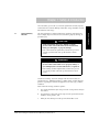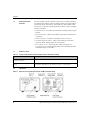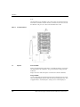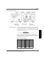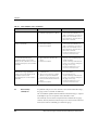
1
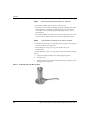
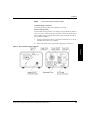
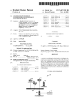
Series 342
Granville-Phillips® Series 342 Ion Gauge Controller
with Digital Display built for Agilent Technologies
Model #G3882A
Instruction Manual
Instruction manual part number 342077
Revision C - October 2014
Series 342
Granville-Phillips® Series 342 Ion Gauge Controller
with Digital Display built for Agilent Technologies
Model #G3882A
This Instruction Manual is for use only with Granville-Phillips
Series 342 Controller built for Agilent Technologies. A list of
applicable catalog numbers is provided on the following page.
For Customer Service or Technical Support 24 hours per day,
7 days per week, every day of the year including holidays:
Phone: +1-800-227-8766 or +1-303-652-4691
MKS, Granville-Phillips Division
6450 Dry Creek Parkway
Longmont, CO 80503 USA
Phone:
FAX:
Email:
1-303-652-4691 or 1-800-776-6543
1-303-652-2844
[email protected]
Corporate Office
MKS Instruments, Inc.
2 Tech Drive, Suite 201
Andover, MA 01810 USA
Phone: 1-978-645-5500
www.mksinst.com
Instruction Manual
© 2014 MKS Instruments, Inc. All rights reserved.
Granville-Phillips® is a are registered trademark and Mini-IonTM is a trademark of MKS
Instruments, Inc. All other trademarks and registered trademarks are the properties of their
respective owners.
Granville-Phillips® Series 342 Ion Gauge Controller
with Digital Display
Catalog numbers for Series 342 Controller and Ion Gauge
Ion Gauge Controller - with digital display:
Ion Gauge
342076
355052E - YD
Table of Contents
Chapter 1
Chapter 2
Safety & Introduction . . . . . . . . . . . . . . . . . . . . . . . . . . . . . . . . .
7
1.1
1.2
1.3
1.4
1.5
7
8
8
8
9
Installation
2.1
2.2
2.3
Step 1
Step 2
Step 3
Step 4
Chapter 3
..........................................
Installation Safety Notices . . . . . . . . . . . . . . . . . . . . . . . . . .
Pressure Relief Devices . . . . . . . . . . . . . . . . . . . . . . . . . . . .
Installation Procedure . . . . . . . . . . . . . . . . . . . . . . . . . . . . .
Mount the Benchtop Mounted Micro-Ion Controller . . . . . .
Install the Micro-Ion Gauge on the Vacuum Chamber . . . .
Connect the Gauge and Power Cables . . . . . . . . . . . . . . . .
System Grounding . . . . . . . . . . . . . . . . . . . . . . . . . . . . . . .
Operation
3.1
3.2
Chapter 4
Caution and Warning Statements . . . . . . . . . . . . . . . . . . . .
Reading and Following Instructions . . . . . . . . . . . . . . . . . .
Definitions of Terms . . . . . . . . . . . . . . . . . . . . . . . . . . . . . .
Specifications . . . . . . . . . . . . . . . . . . . . . . . . . . . . . . . . . . .
Service Guidelines . . . . . . . . . . . . . . . . . . . . . . . . . . . . . . .
...........................................
Theory of Operation . . . . . . . . . . . . . . . . . . . . . . . . . . . . . .
Operation . . . . . . . . . . . . . . . . . . . . . . . . . . . . . . . . . . . . . .
Gas Sensitivity Correction . . . . . . . . . . . . . . . . . . . . . . . . . .
11
11
11
11
12
12
13
14
15
15
16
17
Service & Maintenance . . . . . . . . . . . . . . . . . . . . . . . . . . . . . . . 19
4.1
4.2
4.3
4.4
Service Guidelines . . . . . . . . . . . . . . . . . . . . . . . . . . . . . . .
Damage Requiring Service . . . . . . . . . . . . . . . . . . . . . . . . .
Troubleshooting . . . . . . . . . . . . . . . . . . . . . . . . . . . . . . . . .
Micro-Ion Gauge Continuity Test . . . . . . . . . . . . . . . . . . . .
19
19
20
22
Index . . . . . . . . . . . . . . . . . . . . . . . . . . . . . . . . . . . . . . . . . . . . . . . . . . . . . . . . . . . . . . . . . . . . . . . . . . . . . 25
Series 342 Ion Gauge Controller Instruction Manual p/n 342077-Rev. C
5
Table of Contents
6
Series 342 Ion Gauge Controller Instruction Manual p/n 342077-Rev. C
Chapter 1 Safety & Introduction
The instructions given in this user manual explain how to install, operate,
and maintain the Granville-Phillips® Micro-Ion® Gauge Controller and the
Micro-Ion Vacuum Gauge.
Caution and Warning
Statements
This manual contains Caution and Warning statements with which you
MUST comply to prevent inaccurate measurement, property damage, or
personal injury.
Safety
Installation
& Introduction
1.1
CAUTION
Caution statements alert you to hazards or unsafe
practices that could result in inaccurate measurement,
minor personal injury, or property damage.
Operation Overview
Each caution statement explains what you must do to prevent or
avoid the potential result of the specified hazard or unsafe
practice.
WARNING
Warning statements alert you to hazards or unsafe
practices that could result in severe property damage or
personal injury due to electrical shock, fire, or explosion.
Analog Operation
Each warning statement explains what you must do to prevent
or avoid the potential result of the specified hazard or unsafe
practice.
Caution and warning statements comply with American Institute of
Standards Z535.1–2002 through Z535.5–2002, which set forth voluntary
practices regarding the content and appearance of safety signs, symbols,
and labels.
Each caution or warning statement explains:
The specific hazard that you must prevent or unsafe practice that you
must avoid,
b.
The potential result of your failure to prevent the specified hazard or
avoid the unsafe practice, and
c.
What you must do to prevent the specified hazardous result.
7
Maintenance
Series 342 Ion Gauge Controller Instruction Manual p/n 342077-Rev. C
RS-232 Operation
a.
Chapter 1
1.2
Reading and Following
Instructions
You must comply with all instructions while you are installing, operating,
or maintaining the module. Failure to comply with the instructions violates
standards of design, manufacture, and intended use of the module. MKS
Instruments, Inc. disclaims all liability for the customer's failure to comply
with the instructions.
• Read instructions – Read all instructions before installing or operating the
product.
• Follow instructions – Follow all installation, operating and maintenance
instructions.
• Retain instructions – Retain the instructions for future reference.
• Heed warnings and cautions – Adhere to all warnings and caution
statements on the product and in these instructions.
• Parts and accessories – Install only those replacement parts and
accessories that are recommended by MKS, Granville-Phillips Division.
Substitution of parts is hazardous.
1.3
Definitions of Terms
Table 1-1
Terms Describing the Micro-Ion Vacuum Gauge Controller and the Micro-Ion Gauge
Term
Description
Micro-Ion Gauge Controller, Micro-Ion
Controller, Controller
The Micro-Ion Vacuum Gauge Controller. See Figure 1-1 and Figure 2-2.
Micro-Ion Vacuum Gauge, Micro-Ion
Gauge
The Bayard-Alpert type ionization gauge, which indicates pressure by producing a
current that is proportional to gas density. See Figure 1-1 and Figure 2-1.
1.4
Specifications
Figure 1-1
Dimensions of the Vacuum Gauge Controller and Micro-Ion Vacuum Gauge
8
Series 342 Ion Gauge Controller Instruction Manual p/n 342077-Rev. C
Safety & Introduction
Table 1-2
Specifications of the Vacuum Gauge Controller and the Micro-Ion Vacuum Gauge
Parameter
Specification
Safety
Installation
& Introduction
Controller
Pressure Range
Less than 5 x 10⁻⁸ Torr to 5 x 10⁻³ Torr using 0.1 mAdc emission current
Accuracy
± 5% of reading at ambient temperature of 25 0C (77 0F)
Display Resolution
Scientific notation, 2 significant digits
Display Update Time
0.5 sec.
Electrical
100 - 240 VAC ± 10%, 47 - 63 Hz
Power
25 W Max
Fuse Rating
.50 Amp, Buss MDA 1/2 or Littlefuse 326.500
Enviromental Conditions
Operation Overview
Voltage
Indoor Use Only
0 0C to 40 0C (32 0F - 104 0F)
Altitude
Up to 2000 meters
Maximum Relative Humidity
80% for temperatures up to 31 0C decreasing linearly to 50% relative humidity at 40 0C.
Transient Voltages
Installation Category (overvoltage category) II
Pollution Rating
Degree 2 in accordance with IEC 664
Analog Operation
Temperature Range
Micro-Ion Gauge
11/Torr nominal
Emission Current
0.1 mAdc
Collector Potential
0 Vdc
Grid Potential
+180 Vdc
Filament Potential
+30 Vdc
Service Guidelines
RS-232 Operation
1.5
Sensitivity
See Service Guidelines on page 19.
9
Maintenance
Series 342 Ion Gauge Controller Instruction Manual p/n 342077-Rev. C
Notes:
10
Series 342 Ion Gauge Controller Instruction Manual p/n 342077-Rev. C
2.1
Before You Begin
Chapter 2 Installation
Installation Safety
Notices
WARNING
Using the Micro−Ion Gauge to measure the pressure of
flammable or explosive gases can cause a fire or
explosion resulting in severe property damage or
personal injury.
Do not use the Micro−Ion Gauge to measure the pressure of
flammable or explosive gases.
WARNING
Install the Controller ONLY in an indoor environment.
2.2
Pressure Relief Devices
Before you install the module, you should install appropriate pressure relief
devices in the vacuum system.
2.3
Installation Procedure
The installation procedure includes the following steps:
Mount the benchtop Micro-Ion Gauge Controller
2.
Attach the Micro-Ion Gauge to the vacuum chamber.
3.
Connect the power cable and the Controller/Gauge interconnect
cable.
4.
Connect ground wires between the Micro-Ion Gauge and the vacuum
chamber, and any other ground connections to assure the system is
safe and protects personnel from electrical shock.
11
Maintenance
Series 342 Ion Gauge Controller Instruction Manual p/n 342077-Rev. C
RS-232 Operation
1.
Analog Operation
Granville-Phillips does not supply pressure relief valves or rupture disks.
Suppliers of pressure relief valves and pressure relief disks can be located
via an online search, and are listed on ThomasNet.com under “Relief
Valves” and “Rupture Discs. Confirm that these safety devices are properly
installed before installing and operating the product.
Operation
Installation
Overview
Exposing the Micro−Ion Controller to moisture can
cause fire or electrical shock resulting in severe property
damage or personal injury.
Chapter 2
Step 1
Mount the Benchtop Mounted Micro-Ion Controller
• Locate the Controller where it can be easily accessed.
• For greatest accuracy and repeatability, locate the Controller in a stable,
room-temperature environment. Ambient temperature should never
exceed 40 0C (104 0F) operating, non-condensing, or 85 0C (185 0F)
non-operating.
• Locate the Controller away from internal and external heat sources and
in an area where ambient temperature remains reasonably constant.
Step 2
Install the Micro-Ion Gauge on the Vacuum Chamber
• Do not locate the Gauge near the pump, where gauge pressure might be
lower than normal vacuum pressure.
• Do not locate the Gauge near a gas inlet or other source of
contamination.
The NW16KF flange requires O-rings and centering rings between mating
flanges.
a.
Figure 2-1
12
Tighten the clamp to compress the mating flanges together.
b.
Seal the O-ring.
c.
Connect a ground wire from the Micro-Ion Gauge to a known system
Earth ground. See Figure 2-1.
Ground Connection on the Micro-Ion Gauge
Series 342 Ion Gauge Controller Instruction Manual p/n 342077-Rev. C
Step 3
Connect the Gauge and Power Cables
Before You Begin
Installation
Controller/Gauge Connection:
Connect the provided cable to the Controller and Gauge.
Power Cord Connection:
The Controller will operate over a line voltage range of 100 Vac to 240 Vac
±10%, 47-63 Hz. All that is required is that a line cord be selected to match
your available power receptacle to the power input connector located on
the rear of the Controller.
Connect a ground wire from the ground connection on the rear of the
Controller to a known system ground.
b.
Connect the power cable, but do NOT apply power at this time.
Micro-Ion Gauge Controller Connections
Operation
Installation
Overview
Figure 2-2
a.
Analog Operation
RS-232 Operation
13
Maintenance
Series 342 Ion Gauge Controller Instruction Manual p/n 342077-Rev. C
Chapter 2
Step 4
System Grounding
WARNING
Improper grounding could cause severe product failure
or personal injury.
Follow ground network requirements for the facility.
•
Maintain all exposed conductors at Earth ground.
•
Ground the Micro−Ion Gauge to the vacuum chamber as
illustrated in Figure 2−1.
Check the entire system to be sure all components are properly grounded.
14
Series 342 Ion Gauge Controller Instruction Manual p/n 342077-Rev. C
Before You Begin
Chapter 3 Operation
WARNING
Installation
Using the Micro−Ion Gauge to measure the pressure of
flammable or explosive gases can cause a fire or
explosion resulting in severe property damage, personal
injury, or death.
Do not measure the pressure of flammable or explosive
gases.
WARNING
Exposing the Micro−Ion Controller to moisture can
cause fire or electrical shock resulting in severe property
damage or personal injury.
Install the Controller ONLY in an indoor environment. Do not
install the module in any outdoor environment.
3.1
Theory of Operation
The filament is heated to such a temperature that electrons are emitted, and
accelerated toward the grid by the potential difference between the grid and
filament. All of the electrons eventually collide with the grid, but many first
traverse the region inside the grid many times.
The amount of ion current for a given emission current and pressure
depends on the ion gauge design. This gives rise to the definition of ion
gauge “sensitivity”, frequently denoted by “K”:
K=
RS-232 Operation
When an energetic electron collides with a gas molecule an electron may
be dislodged from the molecule leaving it with a positive charge. Most ions
are then accelerated to the collectors. The rate at which electron collisions
with molecules occur is proportional to the density of gas molecules, and
hence the ion current is proportional to the gas density (or pressure, at
constant temperature).
Analog
Operation
Operation
The functional parts of a typical ionization gauge are the filament (cathode),
grid (anode), and ion collector, which are shown schematically in Figure
3-1. These electrodes are maintained by the gauge controller at +30, +180,
and 0 volts, relative to ground, respectively.
ion current/
(emission current x pressure)
The Micro-Ion Gauge has a sensitivity of 11/Torr when used with nitrogen
15
Maintenance
Series 342 Ion Gauge Controller Instruction Manual p/n 342077-Rev. C
Chapter 3
or air.
The Micro-Ion Gauge Controller varies the heating current to the filament
to maintain a constant electron emission, and measures the ion current to
the collector. The pressure is then calculated from these data.
Figure 3-1
Ion Gauge Illustration
3.2
Operation
Power ON/OFF
Depress the top half of the rocker power switch located on the rear panel to
turn ON power to the Controller. The green LED on the front panel will
illuminate.
Depress the lower half of the power switch to turn OFF the Controller.
Gauge ON/OFF
Use the pushbutton on the front panel to turn the Micro-Ion Gauge ON or
OFF. The digital display will turn ON immediately and display 9.9+9. After
an approximate 6 second delay the actual pressure will be displayed.
16
Series 342 Ion Gauge Controller Instruction Manual p/n 342077-Rev. C
Figure 3-2
Micro-Ion Gauge Controller
Before You Begin
Operation
Installation
Gas Sensitivity Correction
The Micro-Ion Gauge Controller is calibrated to read pressure for nitrogen
or air. If used with other gases, it is required that the pressure reading be
corrected for the gas in use. Table 3-1 gives some typical sensitivity ratios.
To correct the pressure curve reading, divide the indicated pressure reading
by the relative sensitivity ratio.
Gauge Reading
Relative Sensitivity (RX)
Ion gauge sensitivity ratios (RX) shown in Table 3-1 are from NASA
Technical Note TND5285, “Ionization Gauge Sensitivities as Reported in
the Literature,” by Robert L. Summers, Lewis Research Center, National
Aeronautics and Space Administration.
Table 3-1
Gas
Analog
Operation
Operation
True Pressure =
Relative Gas Sensitivities
Gas
RX
He
0.18
H2O
1.12
Ne
0.30
NO
1.16
D2
0.35
Ar
1.29
H2
0.46
CO2
1.42
N2
1.00
Kr
1.94
Air
1.00
SF6
2.5
O2
1.01
Xe
2.87
17
Maintenance
Series 342 Ion Gauge Controller Instruction Manual p/n 342077-Rev. C
RS-232 Operation
RX
Chapter 3
Notes:
18
Series 342 Ion Gauge Controller Instruction Manual p/n 342077-Rev. C
4.1
Service Guidelines
Before You Begin
Chapter 4 Service & Maintenance
If a qualified service person makes repairs at the component level, repairs
properly made with equivalent electronic parts and rosin core solder do not
void the warranty.
If the product requires service, contact the MKS, Granville-Phillips Division
Customer Service Department at +1-800-227-8766 or +1-303-652-4691
for troubleshooting help over the phone.
If the product must be returned to the factory for service, request a Return
Material Authorization (RMA) from Granville-Phillips. Do not return
products without first obtaining an RMA. In some cases a hazardous
materials document may be required. The MKS/Granville-Phillips Customer
Service Representative will advise you if the hazardous materials document
is required.
MKS, Granville-Phillips Division
6450 Dry Creek Parkway
Longmont, CO 80503 USA
Phone: 1-303-652-4691 or 1-800-776-6543
FAX: 1-303-652-2844
4.2
Damage Requiring
Service
Analog Operation
For Customer Service or Technical Support 24 hours per day, 7 days per
week, every day of the year including holidays:
Phone: +1-800-227-8766 or +1-303-652-4691
Email:[email protected]
Operation Overview
When returning a products to Granville-Phillips, be sure to package the
products to prevent shipping damage. Circuit boards and modules
separated from the gauge assembly must be handled using proper anti-static
protection methods and must be packaged in anti-static packaging.
Granville-Phillips will supply return packaging materials at no charge upon
request. Shipping damage on returned products as a result of inadequate
packaging is the Buyer's responsibility.
Disconnect this product from the power source and refer servicing to
Qualified Service Personnel if any the following conditions exist:
• Liquid has been spilled onto, or objects have fallen into, the product.
• The product does not operate normally even if you have followed the
Operation Instructions. Adjust only those controls that are covered in this
instruction manual.
• The product has been dropped or the enclosure has been damaged.
19
Maintenance
Series 342 Ion Gauge Controller Instruction Manual p/n 342077-Rev. C
RS-232
Operation
Service
& Maintenance
• The gauge cable, power-supply cord, or plug is damaged.
Chapter 4
.
CAUTION
Replacement Parts − When replacement parts are
required, be certain to use the replacement parts that
are specified by Granville−Phillips, or that have the
same characteristics as the original parts. Unauthorized
substitutions may result in fire, electric shock, or other
hazards.
CAUTION
Safety Check − Upon completion of any service or
repairs to this product, ask the Qualified Service Person
to perform safety checks to assure that the product is in
safe operating order.
4.3
Troubleshooting
CAUTION
The service and repair information in this manual is for
the use of Qualified Service Personnel. To avoid shock,
do not perform any procedures in this manual or
perform any servicing on this product unless you are
qualified to do so.
CAUTION
Do not substitute parts or modify the product.
Because of the danger of introducing additional hazards,
do not install substitute parts or perform any
unauthorized modification to the product. Return the
product to a service facility designated by
Granville−Phillips for service and repair to ensure that
safety features are maintained. Do not use this product if
it has unauthorized modifications.
20
Series 342 Ion Gauge Controller Instruction Manual p/n 342077-Rev. C
Before You Begin
Service & Maintenance
WARNING
High voltages are present within the power supply of the
Controller, capable of causing electrical shock, injury,
or death. Use extreme caution while troubleshooting
when power is applied to the Controller.
The Controller contains static-sensitive electronic parts, thus the following
precautions must be followed when troubleshooting:
• Use a grounded, conductive work surface. Wear a high impedance
ground strap for personal protection.
• Do not operate the product with static-sensitive devices or other
components removed from the product.
• Do not handle static-sensitive devices more than absolutely necessary,
and only when wearing a ground strap.
Operation Overview
• Use conductive or static dissipative envelopes to store or ship
static-sensitive devices or printed circuit boards.
• Do not use an ohmmeter for troubleshooting MOS circuits. Rely on
voltage measurements.
• Use a grounded, electrostatic discharge safe soldering iron.
Analog Operation
RS-232
Operation
Service
& Maintenance
21
Maintenance
Series 342 Ion Gauge Controller Instruction Manual p/n 342077-Rev. C
Chapter 4
Table 4-1
Failure Symptoms, Causes, and Solutions
Symptom
Possible Causes
Corrective Action
The Power LED does not illuminate.
1. No power to the Controller
2. Controller input power fuse blown
1. Check to be sure proper power is
connected to the Controller. See
Table 1-2 and Step 3 of Section 2.3.
2. Replace the fuse with the correct
type and value as listed on the rear
panel of the Controller.
The Controller fuse blows when the
Power is turned ON.
1. Incorrect power source
2. Incorrect fuse rating
3. Defective Controller
1. Check to be sure proper power is
connected to the Controller. See
Table 1-2 and Step 3 of Section 2.3.
2. Replace the fuse with the correct
type and value as listed on the rear
panel of the Controller.
3. Contact Customer Service. See
Section 4.1 and Section 4.2.
The Micro-Ion Gauge filament does
not turn ON when the Gauge
pushbutton switch is pressed. The
display on the Controller reads 9.9+9
for approximately 30 seconds and then
turns OFF.
1. The Gauge cable is not connected
2. Open filament in the Micro-Ion
Gauge
3. Defective Controller
1. Check to be sure the gauge cable is
properly connected to the gauge
and the Controller
2. Test the continuity of the Micro-Ion
Gauge (see Section 4.4) and replace
the gauge if necessary.
3. Contact Customer Service. See
Section 4.1 and Section 4.2.
The Micro-Ion Gauge filament turns
ON when the Gauge pushbutton
switch is pressed, the display on the
Controller reads 9.9+9 for
approximately 30 seconds and then
turns OFF.
1. Chamber pressure is too high to
permit emission
2. The pressure in the gauge is higher
than the overpressure shutdown
level from the electrometer circuit.
3. Defective filament in the Micro-Ion
Gauge
4. Defective Controller
1. Decrease the pressure in the
vacuum chamber.
2. Decrease the pressure.
3. Test the continuity of the Micro-Ion
Gauge (see Section 4.4) and replace
the gauge if necessary.
4. Contact Customer Service. See
Section 4.1 and Section 4.2.
4.4
Micro-Ion Gauge
Continuity Test
If a problem with pressure measurement is traced to the Micro-Ion Gauge,
the gauge can be tested with an ohmmeter.
This test should be performed ONLY while the Micro-Ion Gauge is exposed
to atmospheric pressure and power to the Controller is OFF.
The continuity test can detect an open filament or shorts between gauge
elements, but may not detect inaccurate pressure measurement associated
with vacuum leaks or adsorbed gases within the gauge.
22
Series 342 Ion Gauge Controller Instruction Manual p/n 342077-Rev. C
Before You Begin
Service & Maintenance
WARNING
Removing or replacing the Micro−Ion Gauge in a high
voltage environment can cause an electrical discharge
through a gas or plasma, resulting in serious property
damage or personal injury due to electrical shock or fire.
Vent the vacuum chamber to atmospheric pressure and turn
OFF power to the Controller before you test, remove, or replace
the Micro−Ion Gauge.
Turn OFF power to the ion gauge Controller.
2.
Measure the resistance of filament pins to the gauge case. The reading
should be infinity.
3.
Measure the resistance across the grid pins. The reading should be
approximately 0 Ω.
4.
Measure the resistance of the grid pins to the gauge case. The reading
should be infinity.
5.
Measure the resistance of the collector pin to the gauge case. The
reading should be infinity.
If resistance values are not the specified values, the Micro-Ion Gauge is
defective. Contact Granville-Phillips customer service to order a
replacement gauge. See Section 4.1.
Figure 4-1
Analog Operation
Use a digital multimeter to measure the resistance between the
filament pins (see Figure 4-1). The reading should be approximately
0.2 Ω.
Operation Overview
1.
Micro-Ion Gauge Controller Connections
RS-232
Operation
Service
& Maintenance
23
Maintenance
Series 342 Ion Gauge Controller Instruction Manual p/n 342077-Rev. C
Chapter 4
Notes:
24
Series 342 Ion Gauge Controller Instruction Manual p/n 342077-Rev. C
Index
Numerics
C
Caution and Warning Statements 7
D
Damage Requiring Service 19
Definitions of Terms 8
Dimensions 8
F
Figures
Dimensions 8
I
Installation
Pressure Relief Devices 11
Procedure 11
Ion Gauge Illustration 16
O
Operation 16
P
Pressure Relief Devices 11
R
Reading and Following Instructions 8
Relative Gas Sensitivities 17
S
Service Guidelines 9, 19
Specifications
Controller 9
Gauge 9
T
Theory of Operation 15
Troubleshooting 20
Series 342 Ion Gauge Controller Instruction Manual p/n 342077-Rev. C
25
Index
26
Series 342 Ion Gauge Controller Instruction Manual p/n 342077-Rev. C
.
Series 342
Granville-Phillips® Series 342 Ion Gauge Controller
with Digital Display for Agilent Technologies
Model #G3882A
For Customer Service or Technical Support 24 hours per day,
7 days per week, every day of the year including holidays:
Phone: +1-800-227-8766 or +1-303-652-4691
MKS, Granville-Phillips Division
6450 Dry Creek Parkway
Longmont, CO 80503 USA
Phone:
FAX:
Email:
1-303-652-4691 or 1-800-776-6543
1-303-652-2844
[email protected]
Corporate Office
MKS Instruments, Inc.
2 Tech Drive, Suite 201
Andover, MA 01810 USA
Phone: 1-978-645-5500
www.mksinst.com
Instruction Manual
Instruction manual part number 342077
Revision C - October 2014