1
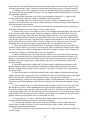
AIRWORTHINESS DIRECTIVE
FAA
Aviation Safety
www.faa.gov/aircraft/safety/alerts/
www.gpoaccess.gov/fr/advanced.html
98-15-18 R1 Maule Aerospace Technology, Inc.: Amendment 39-17690; Docket No. FAA-20130725; Directorate Identifier 98-CE-01-AD.
(a) Effective Date
This AD is effective January 21, 2014.
(b) Affected ADs
This AD revises AD 98-15-18, Amendment 39-10669 (63 FR 39018, July 21, 1998), which
superseded AD 95-26-18, Amendment 39-9476 (61 FR 623, January 9, 1996.)
(c) Applicability
This AD applies to the following Maule Aerospace Technology, Inc. airplanes, all serial
numbers, identified in figure 1 of paragraph (c) of this AD, that are:
(1) Equipped with original equipment manufacturer (OEM) Maule Aerospace Technology, Inc.
rear wing lift struts, part number (P/N) 2079E (or FAA-approved equivalent part numbers), and/or
front wing lift struts, P/N 2080E (or FAA-approved equivalent part numbers), excluding airplanes
equipped with four Maule sealed lift struts, P/N 2200E and P/N 2201E, which are identified by two
raised weld spots on the upper end of the strut just below the serial number plate. Removal of the
upper cuff is needed to locate the weld spots; and
(2) certificated in any category.
Figure 1 to Paragraph (c) of This AD–Applicability
Models
Bee Dee M-4 M-4
M-4C
M-4S
M-4T
M-4-180C
M-4-180S
M-4-180T
M-4-210
M-4-210C
M-4-210S
M-4-210T
M-4-220
M-4-220C
M-4-220S
M-4-220T
M-5-180C
M-5-200
M-5-210C
M-5-210TC
M-5-220C
M-5-235C
M-6-180
M-6-235
M-7-235
M-7-235A
M-7-235B
M-7-235C
MT-7-235
MX-7-160
MX-7-180
MX-7-180A
MX-7-180B
MX-7-235
MX-7-420
MXT-7-160
MXT-7-180
MXT-7-180A M-8-235
(d) Subject
Joint Aircraft System Component (JASC)/Air Transport Association (ATA) of America Code
57, Wings.
5
(e) Unsafe Condition
(1) The subject of this AD was originally prompted by reports of corrosion damage found on the
wing lift struts. We are revising AD 98-15-18, Amendment 39-10669 (63 FR 39018, July 21, 1998),
because of reports that the language in paragraph (b) had been misinterpreted and caused confusion.
Since we issued AD 98-15-18, we were informed by the manufacturer that Model MXT-7-420
airplanes are no longer in existence, are no longer type certificated, and should be removed from the
Applicability section. This AD removes Model MXT-7-420 airplanes from the Applicability section
and clarifies the intent of the language in paragraph (b) of AD 98-15-18, which is being removed by
this AD.
(2) This AD clarifies the FAA's intention that if a sealed wing lift strut assembly is installed as a
replacement part, the repetitive inspection requirement is terminated only if the seal is never
improperly broken. If the seal is improperly broken, then that wing lift strut becomes subject to
continued repetitive inspections. We did not intend to promote drilling holes into or otherwise
unsealing a sealed strut. This AD retains all the actions required in AD 98-15-18 and does not add
any actions over that already required in AD 98-15-18. This AD does not add any additional burden
to the owners/operators of the affected airplanes.
(3) We are issuing this AD to detect and correct corrosion on the front and rear wing lift struts,
which could cause the wing lift strut to fail. This failure could result in the wing separating from the
airplane.
(f) Paragraph Designation Changes to AD 98-15-18
Since AD 98-15-18, Amendment 39-10669 (63 FR 39018, July 21, 1998), was issued, the AD
format has been revised, and certain paragraphs have been rearranged. As a result, the corresponding
paragraph identifiers have changed in this AD, as listed in the following table:
Table 1 to Paragraph (f) of This AD–Revised Paragraph Identifiers
Requirement in AD 98-15-18
Corresponding requirement in this AD
paragraph (a)
paragraph (h)
paragraph (a)(1)
paragraph (i)(1)
paragraph (a)(1)(i)
paragraph (i)(1)(i)
paragraph (a)(1)(ii)
paragraph (i)(1)(ii)
paragraph (a)(2)
paragraph (i)(2)
paragraph (a)(2)(i)
paragraph (i)(2)(i)
paragraph (a)(2)(ii)
paragraph (i)(2)(ii)
paragraph (a)(3)
paragraph (j)(1)
paragraph (a)(4) and (c)
paragraph (j)(2)
paragraph (b)
Removed
(g) Compliance
Unless already done (compliance with AD 98-15-18, Amendment 39-10669 (63 FR 39018, July
21, 1998)), do the following actions within the compliance times specified in paragraphs (h) through
(j) of this AD, including all subparagraphs. Properly unsealing and resealing a sealed wing lift strut is
6
still considered a terminating action for the repetitive inspection requirements of this AD as long as
all appropriate regulations and issues are considered, such as static strength, fatigue, material effects,
immediate and long-term (internal and external) corrosion protection, resealing methods, etc. Current
FAA regulations in 14 CFR 43.13(b) specify that maintenance performed will result in the part's
condition to be at least equal to its original or properly altered condition. Any maintenance actions
that unseal a sealed wing lift strut should be coordinated with the Atlanta Aircraft Certification Office
(ACO) through the local airworthiness authority (e.g., Flight Standards District Office). There are
provisions in paragraph (k) of this AD for approving such actions as an alternative method of
compliance (AMOC).
(h) Remove Wing Lift Struts
At whichever of the compliance times specified in paragraphs (h)(1), (h)(2), or (h)(3) of this AD
that occurs later, remove the wing lift struts following the INSTRUCTIONS section in PART I of
Maule Service Bulletin (SB) No. 11, dated October 30, 1995. Before further flight after the removal,
do the actions in one of the following paragraphs (i)(1), (i)(2), (j)(1), or (j)(2) of this AD, including
all subparagraphs.
(1) Upon accumulating 2 years time-in-service on an OEM Maule wing lift strut, P/N 2079E
and/or P/N 2080E;
(2) Within 3 calendar months after September 9, 1998 (the effective date retained from AD 9815-18, Amendment 39-10669 (63 FR 39018, July 21, 1998)); or
(3) Within 2 years after the last inspection done in accordance with AD 95-26-18, Amendment
39-9476 (61 FR 623, January 9, 1996) (which was superseded by AD 98-15-18).
(i) Inspect Wing Lift Struts
Before further flight after the removal required in paragraph (h) of this AD, inspect each wing
lift strut following paragraph (i)(1) or (i)(2) of this AD, including all subparagraphs, or do the wing
lift strut replacement following one of the options in paragraph (j)(1) or (j)(2) of this AD.
(1) Inspect each wing lift strut for corrosion and perceptible dents following the
INSTRUCTIONS section in PART I of Maule SB No. 11, dated October 30, 1995.
(i) If no corrosion is visible and no perceptible dents are found on any wing lift strut during the
inspection required in paragraph (i)(1) of this AD, before further flight, apply corrosion inhibitor to
each wing lift strut following the INSTRUCTIONS section in PART I of Maule SB No. 11, dated
October 30, 1995. Repetitively thereafter inspect each wing lift strut at intervals not to exceed 24
calendar months following the procedures in paragraph (i)(1) or (i)(2) of this AD, including all
subparagraphs.
(ii) If corrosion or perceptible dents are found on any wing lift strut during the inspection
required in paragraph (i)(1) of this AD or during any repetitive inspection required in paragraph
(i)(1)(i) of this AD, before further flight, replace the affected wing lift strut with one of the
replacement options specified in paragraph (j)(1) or (j)(2) of this AD. Do the replacement following
the procedures specified in those paragraphs, as applicable.
(2) Inspect each wing lift strut for corrosion following the procedures in the Appendix to this
AD. This inspection must be done by a Level 2 or Level 3 inspector certified using the guidelines
established by the American Society for Non-destructive Testing or the ''Military Standard for
Nondestructive Testing Personnel Qualification and Certification'' (MIL-STD-410E), which can be
found on the Internet at http://aerospacedefense.thomasnet.com/Asset/ MIL-STD-410.pdf.
(i) If no corrosion is found on any wing lift strut during the inspection required in paragraph
(i)(2) of this AD and all requirements in the Appendix to this AD are met, before further flight, apply
corrosion inhibitor to each wing lift strut following the INSTRUCTIONS section in PART I of Maule
SB No. 11, dated October 30, 1995. Repetitively thereafter inspect each wing lift strut at intervals not
7
to exceed 24 calendar months following the procedures in paragraph (i)(1) or (i)(2) of this AD,
including all subparagraphs.
(ii) If corrosion is found on any wing lift strut during the inspection required in paragraph (i)(2)
of this AD or during any repetitive inspection required in paragraph (i)(2)(i) of this AD, or if any
requirement in the Appendix of this AD is not met, before further flight after any inspection in which
corrosion is found or the Appendix requirements are not met, replace the affected wing lift strut with
one of the replacement options specified in paragraph (j)(1) or (j)(2) of this AD. Do the replacement
following the procedures specified in those paragraphs, as applicable.
(j) Wing Lift Strut Replacement Options
Before further flight after the removal required in paragraph (h) of this AD, replace the wing lift
struts following one of the options in paragraph (j)(1) or (j)(2) of this AD, or inspect each wing lift
strut following paragraph (i)(1) or (i)(2) of this AD, including all subparagraphs.
(1) Install OEM Maule P/N wing lift struts (or FAA-approved equivalent part numbers) that have
been inspected following the procedures in either paragraph (i)(1) or (i)(2) of this AD, including all
subparagraphs, and are found to be airworthy. Do the installations following the INSTRUCTIONS
section in PART II of Maule SB No. 11, dated October 30, 1995. Repetitively thereafter inspect the
newly installed wing lift struts at intervals not to exceed 24 calendar months following the procedures
in either paragraph (i)(1) or (i)(2) of this AD, including all subparagraphs.
(2) Install new Maule sealed wing lift struts, P/N 2200E or P/N 2201E, as applicable (or FAAapproved equivalent part numbers) following the INSTRUCTIONS section in PART II of Maule SB
No. 11, dated October 30, 1995. Installing one of these new sealed wing lift strut assemblies
terminates the repetitive inspection requirements in paragraphs (i)(1) or (i)(2) of this AD, including
all subparagraphs, for that wing lift strut assembly.
(k) Alternative Methods of Compliance (AMOCs)
(1) The Manager, Atlanta ACO, FAA, has the authority to approve AMOCs for this AD, if
requested using the procedures found in 14 CFR 39.19. In accordance with 14 CFR 39.19, send your
request to your principal inspector or local Flight Standards District Office, as appropriate. If sending
information directly to the manager of the ACO, send it to the attention of the person identified in the
Related Information section of this AD.
(2) Before using any approved AMOC, notify your appropriate principal inspector, or lacking a
principal inspector, the manager of the local flight standards district office/certificate holding district
office.
(3) AMOCs approved for AD 98-15-18, Amendment 39-10669 (63 FR 39018, July 21, 1998)
and AD 95-26-18, Amendment 39-9476 (61 FR 623, January 9, 1996) are approved as AMOCs for
this AD.
(l) Related Information
For more information about this AD, contact Gregory K. Noles, Aerospace Engineer, FAA,
Atlanta ACO, 1701 Columbia Avenue, College Park, Georgia 30337; phone: (404) 474-5551; fax:
(404) 474-5606; email: [email protected].
(m) Material Incorporated by Reference
(1) The Director of the Federal Register approved the incorporation by reference (IBR) of the
service information listed in this paragraph under 5 U.S.C. 552(a) and 1 CFR part 51.
(2) You must use this service information as applicable to do the actions required by this AD,
unless the AD specifies otherwise.
8
(3) The following service information was approved for IBR on January 26, 1996 (61 FR 623,
January 9, 1996).
(i) Maule Service Bulletin No. 11, dated October 30, 1995.
(ii) Reserved.
(4) For Maule Aerospace Technology, Inc. service information identified in this AD, contact
Maule Air, Inc., 2099 GA Hwy 133 South, Moultrie, Georgia 31768; telephone: (229) 985-2045; fax:
(229) 890-2402; Internet:
http://www.mauleairinc.com/pdf/servicebulletins/service_bulletin_11_old.pdf.
(5) You may view this service information at Small Airplane Directorate, 901 Locust, Kansas
City, Missouri 64106. For information on the availability of this material at the FAA, call (816) 3294148.
(6) You may view this service information that is incorporated by reference at the National
Archives and Records Administration (NARA). For information on the availability of this material at
NARA, call 202-741-6030, or go to: http://www.archives.gov/federal-register/cfr/ibr-locations.html.
Appendix to AD 98-15-18 R1
Procedures and Requirements for Ultrasonic Inspection of Maule Wing Lift Struts
Equipment Requirements
1. A portable ultrasonic thickness gauge or flaw detector with echo-to-echo digital thickness
readout capable of reading to 0.001-inch and an A-trace waveform display will be needed to do this
inspection.
2. An ultrasonic probe with the following specifications will be needed to do this inspection: 10
MHz (or higher), 0.283-inch (or smaller) diameter dual element or delay line transducer designed for
thickness gauging. The transducer and ultrasonic system shall be capable of accurately measuring the
thickness of AISI 4340 steel down to 0.020-inch. An accuracy of 0.002-inch throughout a 0.020-inch
to 0.050-inch thickness range while calibrating shall be the criteria for acceptance.
3. Either a precision machined step wedge made of 4340 steel (or similar steel with equivalent
sound velocity) or at least three shim samples of same material will be needed to do this inspection.
One thickness of the step wedge or shim shall be less than or equal to 0.020-inch, one shall be greater
than or equal to 0.050-inch and at least one other step or shim shall be between these two values.
4. Glycerin, light oil, or similar non-water based ultrasonic couplants are recommended in the
setup and inspection procedures. Water-based couplants, containing appropriate corrosion inhibitors,
may be utilized, provided they are removed from both the reference standards and the test item after
the inspection procedure is completed and adequate corrosion prevention steps are then taken to
protect these items.
• NOTE: Couplant is defined as ''a substance used between the face of the transducer and test
surface to improve transmission of ultrasonic energy across the transducer/strut interface.''
• NOTE: If surface roughness due to paint loss or corrosion is present, the surface should be
sanded or polished smooth before testing to assure a consistent and smooth surface for
making contact with the transducer. Care shall be taken to remove a minimal amount of
structural material. Paint repairs may be necessary after the inspection to prevent further
corrosion damage from occurring. Removal of surface irregularities will enhance the accuracy
of the inspection technique.
Instrument Setup
1. Set up the ultrasonic equipment for thickness measurements as specified in the instrument's
user's manual. Because of the variety of equipment available to perform ultrasonic thickness
9
measurements, some modification to this general setup procedure may be necessary. However, the
tolerance requirement of step 13 and the record keeping requirement of step 14, must be satisfied.
2. If battery power will be employed, check to see that the battery has been properly charged.
The testing will take approximately two hours. Screen brightness and contrast should be set to match
environmental conditions.
3. Verify that the instrument is set for the type of transducer being used, i.e. single or dual
element, and that the frequency setting is compatible with the transducer.
4. If a removable delay line is used, remove it and place a drop of couplant between the
transducer face and the delay line to assure good transmission of ultrasonic energy. Reassemble the
delay line transducer and continue.
5. Program a velocity of 0.231-inch/microsecond into the ultrasonic unit unless an alternative
instrument calibration procedure is used to set the sound velocity.
6. Obtain a step wedge or steel shims per item 3 of the Equipment Requirements. Place the probe
on the thickest sample using couplant. Rotate the transducer slightly back and forth to ''ring'' the
transducer to the sample. Adjust the delay and range settings to arrive at an A-trace signal display
with the first backwall echo from the steel near the left side of the screen and the second backwall
echo near the right of the screen. Note that when a single element transducer is used, the initial pulse
and the delay line/steel interface will be off of the screen to the left. Adjust the gain to place the
amplitude of the first backwall signal at approximately 80% screen height on the A-trace.
7. ''Ring'' the transducer on the thinnest step or shim using couplant. Select positive half-wave
rectified, negative half-wave rectified, or filtered signal display to obtain the cleanest signal. Adjust
the pulse voltage, pulse width, and damping to obtain the best signal resolution. These settings can
vary from one transducer to another and are also user dependent.
8. Enable the thickness gate, and adjust the gate so that it starts at the first backwall echo and
ends at the second backwall echo. (Measuring between the first and second backwall echoes will
produce a measurement of the steel thickness that is not affected by the paint layer on the strut). If
instability of the gate trigger occurs, adjust the gain, gate level, and/or damping to stabilize the
thickness reading.
9. Check the digital display reading and if it does not agree with the known thickness of the
thinnest thickness, follow your instrument's calibration recommendations to produce the correct
thickness reading. When a single element transducer is used this will usually involve adjusting the
fine delay setting.
10. Place the transducer on the thickest step of shim using couplant. Adjust the thickness gate
width so that the gate is triggered by the second backwall reflection of the thick section. If the digital
display does not agree with the thickest thickness, follow your instruments calibration
recommendations to produce the correct thickness reading. A slight adjustment in the velocity may be
necessary to get both the thinnest and the thickest reading correct. Document the changed velocity
value.
11. Place couplant on an area of the lift strut which is thought to be free of corrosion and ''ring''
the transducer to surface. Minor adjustments to the signal and gate settings may be required to
account for coupling improvements resulting from the paint layer. The thickness gate level should be
set just high enough so as not to be triggered by irrelevant signal noise. An area on the upper surface
of the lift strut above the inspection area would be a good location to complete this step and should
produce a thickness reading between 0.034-inch and 0.041-inch.
12. Repeat steps 8, 9, 10, and 11 until both thick and thin shim measurements are within
tolerance and the lift strut measurement is reasonable and steady.
13. Verify that the thickness value shown in the digital display is within 0.002-inch of the
correct value for each of the three or more steps of the setup wedge or shims. Make no further
adjustments to the instrument settings.
14. Record the ultrasonic versus actual thickness of all wedge steps or steel shims available as a
record of setup.
10
Inspection Procedure
1. Clean the lower 18 inches of the wing lift struts using a cleaner that will remove all dirt and
grease. Dirt and grease will adversely affect the accuracy of the inspection technique. Light sanding
or polishing may also be required to reduce surface roughness as noted in the Equipment
Requirements section.
2. Using a flexible ruler, draw a 1/4-inch grid on the surface of the first 11 inches from the lower
end of the strut as shown in Maule Air, Inc. Service Bulletin No. 11, dated October 30, 1995, as
applicable. This can be done using a soft (2) pencil and should be done on both faces of the strut. As
an alternative to drawing a complete grid, make two rows of marks spaced every 1/4 inch across the
width of the strut. One row of marks should be about 11 inches from the lower end of the strut, and
the second row should be several inches away where the strut starts to narrow. Lay the flexible ruler
between respective tick marks of the two rows and use tape or a rubber band to keep the ruler in
place. See Figure 1.
3. Apply a generous amount of couplant inside each of the square areas or along the edge of the
ruler. Re-application of couplant may be necessary.
4. Place the transducer inside the first square area of the drawn grid or at the first 1/4-inch mark
on the ruler and ''ring'' the transducer to the strut. When using a dual element transducer, be very
careful to record the thickness value with the axis of the transducer elements perpendicular to any
curvature in the strut. If this is not done, loss of signal or inaccurate readings can result.
5. Take readings inside each square on the grid or at 1/4-inch increments along the ruler and
record the results. When taking a thickness reading, rotate the transducer slightly back and forth and
experiment with the angle of contact to produce the lowest thickness reading possible. Pay close
attention to the A-scan display to assure that the thickness gate is triggering off of maximized
backwall echoes.
NOTE: A reading shall not exceed .041 inch. If a reading exceeds .041 inch, repeat steps 13 and
14 of the Instrument Setup section before proceeding further.
6. If the A-trace is unsteady or the thickness reading is clearly wrong, adjust the signal gain
and/or gate setting to obtain reasonable and steady readings. If any instrument setting is adjusted,
repeat steps 13 and 14 of the Instrument Setup section before proceeding further.
7. In areas where obstructions are present, take a data point as close to the correct area as
possible.
NOTE: The strut wall contains a fabrication bead at approximately 40% of the strut chord. The
bead may interfere with accurate measurements in that specific location.
8. A measurement of 0.024 inch or less shall require replacement of the strut prior to further
flight.
9. If at any time during testing an area is encountered where a valid thickness measurement
cannot be obtained due to a loss of signal strength or quality, the area shall be considered suspect.
These areas may have a remaining wall thickness of less than 0.020-inch, which is below the range of
this setup, or they may have small areas of localized corrosion or pitting present. The latter case will
result in a reduction in signal strength due to the sound being scattered from the rough surface and
may result in a signal that includes echoes from the pits as well as the backwall. The suspect area(s)
shall be tested with a Maule ''Fabric Tester'' as specified in Maule Air, Inc. Service Bulletin No. 11,
dated October 30, 1995.
10. Record the lift strut inspection in the aircraft log book.
11
Issued in Kansas City, Missouri, on November 22, 2013.
Earl Lawrence,
Manager, Small Airplane Directorate,
Aircraft Certification Service.
12