1
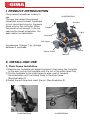
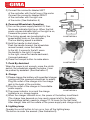
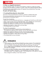
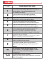
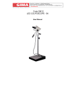
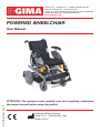
PROFESSIONAL MEDICAL PRODUCTS
Gima S.p.A. - Via Marconi, 1 - 20060 Gessate (MI) Italy
Italia: tel. 199 400 401 - fax 199 400 403
Export: tel. +39 02 953854209/221/225 fax +39 02 95380056
[email protected] - [email protected]
www.gimaitaly.com
POWERED WHEELCHAIR
M27729-EN-Rev.0-07.11
User Manual
ATTENTION: The operators must carefully read and completely understand
the present manual before using the product.
Fabbricante/Manufacturer:
Gima S.p.A. - Gessate (MI) - Italy
Made in P.R.C
1
I. PRODUCT INTRODUCTION
The powered wheelchair is easy to
use.
The user can make the powered
wheelchair move forward, backward
or turn round and round in the same
place only by the controller. When
the power is not enough, it can be
used as the transit wheelchair. The
seat cushion is detachable.
Illustration 1
Armrest
Handle
Light
Controller
Anti-tipper
Accessories: Charger 1 pc, storage
batteries 2 purchase.
Castor
Power wheel
Footrest
II. INSTALL AND USE
1. Chair Frame Installation
1)Remove the footplate just adjust the locker, then swing the footplate
to the side, pull up the footplate until it is out of the chair frame fully
2)Put the footplate to the chair frame by side, push it towards
the wheelchair until it is locked firmly in the chair frame.
(See illustration 2)
3)Install the anti-tiper and insert the pin. (See illustration 3)
Illustration 2
Illustration 3
2
TABLE 1 main parameters
1. Outer Dimension
1020(L)X650(W)X990(H)mm
10. Over Obstacle
40mm
2. Light
24V 5W
11. Stop Distance
1m
3. Net Weight
50kg
incl. Batteries
12. Running Distance
Per Charging
20km
4. Capacity
13. Noise
≤65dBA
Max: 110kg
5. Castor Diameter
200mm (8 )
14. Power Spec
2x12V=24V,
24Ah
6. Driving Wheel
330mm (12.5 )
15. Get Over Channel
≤100mm
7. Seat Width
400(L)x410(W)mm
16. Motor Spec
168Wx2
8. Speed
0-6km/h
17. Charging Current
3.5A
9. Creeping Capacity
12°
18. Charging input
AC 220V
2. Battery Installation
When the batteries need to change,
put two new storage batteries to the
same direction in the battery box.
Connect the anode of A battery
and the cathode of B battery with
a short wire. Connect the anode of B
run with the red short wire,
and the cathode of A battery with the
blue short wire. Then cover the battery box.
Illustration 4
3. Battery Box Installation
1)Open the wheelchair, lift the battery box,
then hang the hooks of the box
to the battery box support pole.
2)Connect the power connector of the
controller with the one of batteries box.
4. Backrest angle adjusting
You would better adjust the backrest angle
before using the wheelchair or do this
operation by assistant. Just unscrew the
adjustable knob, choose the right angel you
want, fasten the knobs after any adjustment.
(See illustration 4)
Illustration 5
5.Controller Installation
1)Insert the controller support to the controller fixing cover beside
the armrest, adjust the position of the controller and fasten the screw nut.
(See illustration 5)
3
2)Connect the connector labeled LEFT
of the controller with the left one of the motor.
Connect the connector labeled RIGHT
of the controller with the right one
of the motor. (See illustration 6)
6. Powered Wheelchair Operation
1)Turn on the power supply switch I/O, then
the power indicator light is on. When the first
power volume indicator light on the right is on,
it means the power is enough.
2)The driving speed can be adjusted by the
speed adjust knob on the controller.
The low starting speed is suitable.
3)Hold the handle to start slowly.
Push the handle forward, the wheelchair
moves forward; move the handle
to the left, it moves to the left; move
the handle to the right, it moves
to the right, move the handle backward,
it moves backward.
4)Press the trumpet button to make alarm.
7. Push By Assistant
When the power is not enough, move the clutch
switch, the wheelchair release the brake, it can
be pushed by assistant. (See illustration 7)
PG
MOTOR
MOTOR
BATTERIES
Illustration 6
Illustration 7
8. Charge
1)Please charge the battery with specified charger
coming with the powered wheelchair for safety.
Plug the outlet of the charger into the charge
jack in the back of the controller.
2)Plug the outlet of the charger in the suitable
power supply.
Illustration 8
3)The power indicator is on and the charge
indicator is on, charge begins.
4)When the charger indicator is on, the power of the battery is sufficient.
(The charge time depends on how much power is left in the battery.
A newstorage battery needs to charge 12-14 hours for the first time.)
After charge, take out the outlets of the power supply and charge output.
9. Lighting lamp
Operate the on/off button to turn on or turn off the lighting lamp.
The button is under the armrest. (See illustration 8)
4
10.Slow or sluggish movement
If the wheelchair does not travel at full speed or does not respond quickly
enough, and the battery condition is good, check the maximumspeed setting.
If adjusting the speed setting does not remedy the problemthen there may
be a non-hazardous fault.
Contact your service agent.
11.Locking/Unlocking the wheelchair
The VR 2 control systemcan be locked to prevent unauthorized use.
The locking method is via a sequence of key presses and joystick
movements, as detailed below.
To lock the wheelchair.
•While the control systemis switched on, depress and hold the on/off button.
•After 1 second the control systemwill beep. Now release the on/off button.
•Deflect the joystick forwards until the control systembeeps.
•Deflect the joystick in reverse until the control systembeeps.
•Release the joystick, there will be a long beep.
•The wheelchair is now locked.
To unlock the wheelchair
•Use the on/off button to switch the control system on.
The maximum speed/profile indicator will be ripping up and down.
•Deflect the joystick fowards until the control system beeps.
•Deflect the joystick in reverse until the control systembeeps.
•Release the joystick, there will be a long beep.
•The wheelchair is now unlocked.
REMARKS
1.The six lights of the indictors indicate the power volume. The wheelchair can be charged when the third yellow light on the left in the control box
is on. The power is exhausted when the second red light on the left
is on, please charge immediately otherwise the battery will be damaged
and can`t be charged.
2.In order to make the battery more durable, please charge the battery
frequently to make it sufficient. If the wheelchair is not used, take out
the battery after it is charge enough. If the wheelchair is not used for a long
time, charge the battery once three months.
5
3.The power wheelchair is suitable to drive in wide room, path and flat
roadaround residences. Don’t go close the motor vehicles, deep holes
and water.
4.Don’t run across the steps often in order to avoid damage of the front castors
5.Don’t climb long slope in case the circuit of the motor is overload and
the power is used too fast or accident happens if the user cannot stop
the wheelchair in time in the middle of the slope.
6.The accessory castors uses in case the wheelchair is overturn when
the slope is too inclined. Don’t detach them.
7.When it is necessary to stop the wheelchair during driving, move
the handle of the controller to the original position and it will brake
automatically. When stop the wheelchair on the slope, it can brake
automatically to stay on the slope.
8.Please see whether the air in the tyres of the front castors and rear
wheels are sufficient before use. If it is not sufficient, please inflate
the tyres in time. The air pressure should be 3kgf/cm2~4kgf/cm2 .
9.Please check whether the connectors connect one another well, the strew
nuts are loose. Adjust them in time.
10. If need to fold the wheelchair, take out the electric connectors
and the battery box and pull up the middle of the upholstery to fold it.
11. If need to disassemble the controller, take out the connectors of controller
with the motors and batteries, release the adjusting knob then
the controller can be taken out from the cover.
12.Heavy patient and mental illness are inadequate to use the electric
wheelchair.
13.Because the backrest can automatically recover to the original position,
if nobody is on the wheelchair under the lying position, please don’t pull the backrest adjusting lever.
MAINTENANCE
Clean every part of the wheelchair frequently
SELF-HELP GUIDE
If a systemtrip occurs, you can find out what has happened by counting
the number of bars on the battery gauge that are flashing.
Belowis a list of self-help actions. Try to use this list before you
contact your service agent. Go to the number in the list which
matches the number of flashing bars and follow the instructions.
If the problempersists after you made the checks described
above contact your service agent.
6
Flashing bars
number
TROUBLESHOOTING GUIDE
1
The battery needs charging or there is a bad
connection to the battery. Check the connections
to the battery. If the connections are good,
try charging the battery.
2
The left hand motor has a bad connection.
Check the connections to the left hand motor.
3
4
The left hand motor has a short circuit to a battery
connection. Contact your service agent.
5
The right hand motor has a short circuit to a
battery connection. Contact your service agent.
6
The wheelchair is being prevented fromdriving
by an external signal. The exact cause will
depend on the type of wheelchair you have,
one possibility is the battery charger is connected.
7
A joystick fault is indicated.
Make sure that the joystick is in the center position
before switching on the control system.
8
A control systemfault is indicated. Make sure
that all connections are secure.
9
The parking brakes have a bad connection.
Check the parking brake and motor connections.
Make sure the control system connections are
secure.
10
7+S
The right hand motor has a bad connection.
Check the connections to the right hand module.
An excessive voltage has been applied to the
control system. This is usually caused by a poor
battery connection. Check the battery
connections.
A comunication fault is indicated.
Make sure that joystick cable is securely connected
and not damaged.
Disposal: The product must not be disposed of along with other
domestic waste. The users must dispose of this equipment by
bringing it to a specific recycling point for electric and electronic
equipment. For further information on recycling points contact
the local authorities, the local recycling center or the shop where
the product was purchased. If the equipment is not disposed
of correctly, fines or penalties may be applied in accordance
with the national legislation and regulations.
GIMA WARRANTY CONDITIONS
Congratulations for purchasing a GIMA product. This product meets high
qualitative standards both as regards the material and the production.
The warranty is valid for 12 months from the date ofsupply of GIMA.
During the period of validity of the warranty, GIMA will repair and/or replace
free of charge all the defected parts due to production reasons. Labor costs
and personnel traveling expenses and packaging not included.
All components subject to wear are not included in the warranty.
The repair or replacement performed during the warranty period shall not
extend the warranty. The warranty is void in the following cases: repairs
performed by unauthorized personnel or with non-original spare parts, defects
caused by negligence or incorrect use. GIMA cannot be held responsible
for malfunctioning on electronic devices or software due to outside agents
such as: voltage changes, electro-magnetic fields, radio interferences, etc.
The warranty is void if the above regulations are not observed and if the serial
code (if available) has been removed, cancelled or changed.
The defected products must be returned only to the dealer the product was
purchased from. Products sent to GIMA will be rejected.