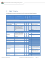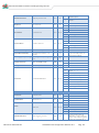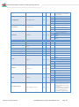
1
Innovative Software Solutions and Engineering Services Installation and Configuration Manual OPC Server FibroLaser III Installation and Configuration Manual Revision History: Version 1.0 Date Sep 2015 Status Released Property of S4S - Innovative Software Solutions and Engineering Services We reserve all rights in this document and in the subject thereof. By acceptance of the document the recipient acknowledges these rights and undertakes not to publish the document nor the subject thereof in full or in part, nor to make them available to any third party without our prior express written authorization, nor to use it for any purpose other than for which it was delivered to him. Innovative software solutions and Engineering Services S4S - Via Vespucci 6 - 20018 - Sedriano (MI) – Italy - VAT 05172500968 Tel. +39 3939505055 - Fax. +39 02 36547223 - Email: [email protected] IC_OPC Server FibroLaser III - Doc.n° IC-001-015 V1.0 Updated Sep 2015. Specifications subject to change without notice. Please visit our website for the most up-to-date product information. www.s4s.it All Rights Reserved. Innovative Software Solutions and Engineering Services Table of Contents 1. Glossary ............................................................................................................................................................ 3 2. Introduction .................................................................................................................................................... 3 3. About the OPC Server FibroLaser III ...................................................................................................... 4 4. System Requirements.................................................................................................................................. 5 5. Installation guide .......................................................................................................................................... 6 5.1 Registration of the OPC Server ............................................................................................................ 6 5.2 Authentication and Permissions .......................................................................................................... 7 5.3 Licensing .................................................................................................................................................... 12 5.3.1 How to obtain a license .................................................................................................................. 12 5.3.2 Software license activation ............................................................................................................ 12 6. System Configuration............................................................................................................................... 13 6.2.1 FibroLaser IIII controller (OTS30XX) ............................................................................................ 13 6.2.2 OPC Server ........................................................................................................................................... 15 7. OPC TAGs ...................................................................................................................................................... 23 OPC Server FibroLaser III Installation and Configuration Manual V1.0 Pag .2 Innovative Software Solutions and Engineering Services 1. Glossary Acronym OPC OLE GUI SCADA Description OLE for Process Control Object Linking and Embedding Graphic User Interface Supervisory Control And Data Acquisition FibroLaser III Siemens Linear Heat Detection systems OTS30xx Siemens Linear Heat Detection Controllers 2. Introduction This is a User Manual for the OPC Server FibroLaser III . The Server communicates with FibroLaser III controllers over Ethernet and supports data exchange with Client's via Microsoft's Object Linking and Embedding (OLE) for Process Control (OPC). S4S’s OPC Server is a software package that operates as an OPC driver of Siemens Management stations as MM8000, Desigo CCTM and CerberusTM DMS. The OPC Server meets the latest standard of OPC DA2.0 that allows connections to various kinds of devices and host OPC machines. The manual is organized to provide an overview of OPC technology, detailed information on the configuration environment and a complete list of OPC Tag’s provided by the OPC Server. OPC Server FibroLaser III Installation and Configuration Manual V1.0 Pag .3 Innovative Software Solutions and Engineering Services 3. About the OPC Server FibroLaser III The OPC Server FibroLaser III is based on OPC Data Access, known as 'DA', which provides real-time data from FibroLaser III controllers to management stations with OPC client drivers as MM8000, DesigoCCTM and CerberusTM DM. The server communicates with OTS 30xx via the LON protocol over TCP-IP Protocol has been designed to be compatible with the previous versions of the OTS public code protocols. The OPC Server reads and writes data to and from FibroLaser III controllers via Ethernet. The Server has a graphical user interface (GUI) configuration environment with an "Explorer" look and feel. The configuration environment allows the Server to be configured with information such as controller IP addresses and available global variables so that the Server can communicate with these systems on behalf of Clients. Application Name OPC NAME OPC DESCRIPTION OPC GUID OPC Server FibroLaser III : OPC-FibroLaserIII.exe : "S4S.OPC-FibroLaser III" (Can be configured in xml file) : "OPC Server – FibroLaser III" (Can be configured in xml file) : {4DA870F2-A36A-46FF-BD36-A21511B9FF80} Installation and Configuration Manual V1.0 Pag .4 Innovative Software Solutions and Engineering Services 4. System Requirements The OPC Server FibroLaser III application runs on any hardware which supports Windows Server 2003/2008/2012, Windows XP, Windows 7 or Windows 8 with DCOM, Visual C++ 2010 Redistributable Packages and .NET Framework 4 Installed. The system must have 10 Mb of free disk space to install the program and 1 Gb of free memory is required to load and run the application. All systems information is stored in the server’s disk. For configuration purpose a monitor connected to the computer is required. The OPC server is a 32 bit application which runs on both 32/64 bit operating systems. Hardware characteristics recommended - CPU i5 high-end (for example INTEL Core i5 4690K) or i7 mid-range (for example Intel Core i7-4770K) RAM : 8GB Checks on the network Since the Server communicates with the FibroLaser OTS 30XX over TCP-IP, an Ethernet network must be in place. The network itself should be fully tested and be known to operate before attaching the controllers and the Server computers. Contact your system administrator for assistance or consult instructional documentation and manuals to setting up the network. It is beyond the scope of this Users Manual to discuss networking topics in any detail. Once the network is in place and the Server computers and controllers are attached, check connectivity using available network testing tools and programs such as ping command. Note: When the OTS 30XX configuration is modified, a re-start of the LON Protocol is carried out and a disconnection on communication is detected. OPC Server FibroLaser III Installation and Configuration Manual V1.0 Pag .5 Innovative Software Solutions and Engineering Services 5. Installation guide Before installation of the OPC server, make sure it is installed the Visual C++ 2010 Redistributable Packages, if not please let install it on your computer. The OPC Server FibroLaser III is provided with own specific setup. The setup includes all the dependencies (ex. WtOPCSvr.DLL - OPC server library) in order to ensure the proper functioning of the application. S4S_OPC_Library.dll S4SGenCodeInfo.dll S4SGenCodeInfoLibrary.dll ObjectListView.dll WtOPCSvr.dll SysInfo.dll Two security issues require attention: Installation needs Administrator rights; Windows Firewall must be configured; DCOM security settings must be configured. This guide describes how to make the necessary settings. 5.1 Registration of the OPC Server Image 1 Register and UnRegister To register the Server, you must click 'Register' in the menu 'Server'. To unregister the OPC Server, you must click 'UnRegister' in the menu 'Server'. OPC Server FibroLaser III Installation and Configuration Manual V1.0 Pag .6 Innovative Software Solutions and Engineering Services 5.2 Authentication and Permissions After OPC Server registration the COM security has to be enabled, so OPC Client can automatically call the OPC Server. Below are showed all steps needed to enable the security COM, using ‘DCOMCNFG1’: 1. Verify that the DCOM security registration was executed successfully; 2. Run DCOMCNFG (Only the administrator can run ‘Dcomcnfg.exe’). To use ‘RUN Command Windows’ or ‘Command Prompt’ , to open DCOMCNFG program; Image 2 DCOMCNFG - Run 3. Locate the My Computer item by expanding the following nodes: Component Services > Computers; 4. Right-click My Computer and select Properties. Image 3 Component Services Property 1 Dcomcnfg.exe provides a user interface for modifying certain settings in the registry. By using Dcomcnfg.exe, you can enable security either on a computer-wide or a process-wide basis. You can enable security for a particular computer so that when a process does not provide its own security settings, either programmatically or through registry values, the values set by Dcomcnfg.exe will be used. Or you can use Dcomcnfg.exe to enable security for a particular application only. Note:You must be an administrator to run Dcomcnfg.exe. OPC Server FibroLaser III Installation and Configuration Manual V1.0 Pag .7 Innovative Software Solutions and Engineering Services 5. Go to the COM Security tab. Edit the default settings to Access Permission, hereby adding ‘ANONYMOUS LOGON’ and ‘Everyone’ and giving all access permissions to that group of users. Repeat the setup for the limit settings. Image 4 COM Security Access Permissions 6. Now edit the default settings for Launch and Activation Permissions, hereby adding ‘ANONYMOUS LOGON’ and ‘Everyone‘ and giving all access permissions to that group of users. Repeat the setup for the limit settings. Image 5 COM Security Launch and Activation Permissions The new settings will take effect when the OPC Client has been restarted. Therefore, close the Component Services (dcomcnfg program) and restart the OPC Client application. OPC Server FibroLaser III Installation and Configuration Manual V1.0 Pag .8 Innovative Software Solutions and Engineering Services 7. Using tree view DCOMCMFG to check the all DCOM registered. Image 6 DCOMCMFG Select the 'Component Services' item, than 'Computers', than 'My Computer' and 'DCOM Config' item; Find the OPC Server name registered in the DCOM list, it must be the same as configured in the xml file. Xml file example: <OPC_PROTOCOL Delimiter="." OPC_name=”OPC-SERVER" OPC_description="OPC Server - Fibro Laser" …> OPC Server name is registered: “OPC-Fibro Laser”, for this example the name is “OPC-SERVER”. Image 7 DCOMCNFG - Find OPC Server OPC Server FibroLaser III Installation and Configuration Manual V1.0 Pag .9 Innovative Software Solutions and Engineering Services 8. OPC Server Configuration Permissions. Select the ‘OPC-SERVER’ registration then the properties (pushing the right button) and then select the ‘security’ tab: a. Select ‘Customize’ in the 'Configuration Permissions’ and then click the ‘Edit’ button. Image 8 DCOMCNFG – Configuration Permissions b. Select ‘Add’ button to add a new user and then, in the new form, select the ‘Advanced’ button. c. Click the ‘Find’ button to search the ‘everyone’ and then ‘ANONYMOUS LOGON ‘ users. Image 9 DCOMCNFG – Find User OPC Server FibroLaser III Installation and Configuration Manual V1.0 Pag .10 Innovative Software Solutions and Engineering Services d. Add ‘everyone’ and ‘ANONYMOUS LOGON ‘ user; Image 10 DCOMCNFG - Add users e. Provide all permission to added users. 9. Set OPC Server identity. Select the ‘identity’ tab: Set ‘This user’ and insert User and Password used to access MM8000. Image 11 DCOMCNFG – Identity Note: The demo version runs only with Launching or Interactive User. A different user from Launching or Interactive can be used ONLY if the OPC-Server runs with a registered PAK. OPC Server FibroLaser III Installation and Configuration Manual V1.0 Pag .11 Innovative Software Solutions and Engineering Services 5.3 Licensing To run the OPC Server without any time restriction a regularly software license has to be purchased from S4S. A software license defines the maximum configuration managed by the OPC Server in terms of: - N° of FibroLaser III controllers (OTS30xx) - N° of channels per OTS30xx (Optic fibers) - Length of Optic Fiber (1,2,4,6,10 Km) per OTS30xx Without the software license the OPC Server FibroLaser III runs in demo mode with full functionality for two hours. The demo mode runs only with Launching or Interactive User (see OPC Server identity 9). 5.3.1 How to obtain a license A software license must be obtained from S4S and the request has to be done from the computer where is installed the OPC Server. From the its User Interface selecting “?” then “Information about OPC Server FibroLaser III” then “View license” then “Product activation”. In the 'Product Activation' the following fields have to be filled : Customer installation data o User name, o Organization, o Email, OTS 30XX configuration in terms of: numbers of FibroLaser III controllers, numbers of channels for controller and fiber length per channel; Code generation (via the 'Generate new user code' button); Save the code and directly send it to '[email protected] ' or send it via 'Send' button if it is configured a mail box on the computer. A PAK (Program Authorization Key) code will be generated for that specific configuration and for the PC from which has been requested the software license. 5.3.2 Software license activation To activate your license you must access to the 'Product Activation' dialog and through the 'Load New License' button you load the license file released by S4S. A dialog will appear for feedback at the end of loading to indicate the outcome of activation. OPC Server FibroLaser III Installation and Configuration Manual V1.0 Pag .12 Innovative Software Solutions and Engineering Services 6. System Configuration The purpose of this section is to provide the necessary information for configuring the FibroLaser III controller and the OPC Server. 6.2.1 FibroLaser IIII controller (OTS30XX) To enable the communication with the OPC-Server, the OTS30xx has to be configured setting connection parameters and enabling the LON protocol. The following screen shows how to configure the OTS30XX via Fibro Manager windows application. Image 12 - FibroLaser III Communication Settings In the Network Settings section it is possible to set the OTS30XX IP address. This IP address will be used by the OPC Server configuration tool to connect the FibroLaser III controller . Image 13 FibroLaser III Network Settings OPC Server FibroLaser III Installation and Configuration Manual V1.0 Pag .13 Innovative Software Solutions and Engineering Services In the LON Protocol section, to enable the LON Protocol, select the check-box "Use TCP" and then set the communication Port. The value of the Port will be set in the OPC Server to connect the OTS30xx. In the transmitted data section is possible to define which data type the OTS30XX has to be transmitted: Notices, Alarms, Alarm locations, Zone Minimum temperature, Zone Maximum temperature, Zone Mean temperature, Temperature data and backscattering data. For MM8000 (Danger Management System) is sufficient to enable the following data: Notices, Alarms and Alarm locations, for system as Desigo CCTM, CerberusTM DMS, WinCC and SCADA, can be enabled the following data : Notices, Alarms, Alarm locations, Zone Minimum temperature, Zone Maximum temperature, Zone Mean temperature, Temperature data Transmitted data setting for MM8000 : Image 14 FibroLaser LON Protocol Transmitted data setting for MM8000 OPC Server FibroLaser III Installation and Configuration Manual V1.0 Pag .14 Innovative Software Solutions and Engineering Services Transmitted data setting for DesigoCC, Desigo Insight, SCADA : Image 15 FibroLaser LON Protocol Transmitted data setting for DesigoCC 6.2.2 OPC Server After a successful installation, the OPC Server has to be configured in order to communicate with the OTS 30xx and acquire data from it. The OPC Server FibroLaser III configuration tool consists of two sections: Settings and Subsystems. SETTINGS: Is the section where to define the OPC Server general parameters; SUBSYSTEMS: Is the section where to configure the subsystems (FibroLaser III controllers) that the OPC Server has to connect. OPC Server FibroLaser III Installation and Configuration Manual V1.0 Pag .15 Innovative Software Solutions and Engineering Services SETTINGS The SETTINGS section allows configuring the OPC Server name and description and the main operating parameters: Image 16 OPC Server – SETTINGS OPC Server After entering the OPC Server name and description you must register the application with the command "Register". In case you want to change the name and description you must first unregister it then register it again with the new name. Operating Parameters OPC Quality behavior Enables or disables the management of the quality property in accordance with the standard OPC. Default is : Enabled System Status Update (s): Polling delay in seconds for updating the OTS 30xx status. Range Value: 1-3600 [s] Default value: 3 [s]. OPC Server FibroLaser III Installation and Configuration Manual V1.0 Pag .16 Innovative Software Solutions and Engineering Services Level Log Detail : Defines the level of detail of OPC LOGs presented on the screen. Three levels are supported : LOW, MEDIUM and HIGH - LOW - [Default value] – Presents the system diagnostics and commands received from an OPC client . MEDIUM – Presents all OPC transactions (change of status, commands, diagnostics). HIGH - Presents all OPC transactions (change of status, commands, diagnostics) with the native messages sent by the OTS. \). The detail level is verbose and can slow down the application. Normally used only for Debug. All logs are saved on a File.txt (C:\OPC- FibroLaser \LOG. Number Retry Msg Number of polling messages sent to the OTS30xx, without any response, before to set the communication status to disconnected. Range Value: 1-50 - Default value: 5 Default Value TAG Default value assigned when the OPC Server does not know the real value of TAGs, for example at the start-up of the OPC. Default value is : -1. Path logo image : Defines the logo to be presented on top of the application. Defaul value : S4S logo Alarm-Prealarm behavior : Defines how to handle the zone alarm and prealarm OPC tags : - FibroLaserIII : The alarm and pre-alarm value are aligned with the value sent by the FibroLaserIII, so you can have both alarm and pre-alarm active - Alarm-Prealarm : In this case when a zone alarm tag is set to a value active the pre-alarm tag of the same zone is set to a value no-active. Default value: FibroLaserIII Ack-Reset behavior : Defines how to handle the event status of an OPC tag value : - FibroLaserIII : The OPC tag value takes the value sent by the FibroLaserIII (0=no active, 1 = active). - Ack-Reset : The OPC tag value is set in accordance to the Ack and Reset commands sent to the OTS. Es. 0 = event not-active, 1= event active, 2=event silenced (Ack command sent) and ready to be reset. After the command reset the value return to the value = 0. Default value: FibroLaserIII Delimiter Export CSV file : Defines the delimiter character used in the CSV file. Default value: ; OPC Server FibroLaser III Installation and Configuration Manual V1.0 Pag .17 Innovative Software Solutions and Engineering Services Export full CSV file : Whether NOT checked the CSV export file contains the following data; Full Tag name Tag description text OPC Class SUBSYSTEM_1.FIBRO_CHANNEL_1.Connection Connection 1 SUBSYSTEM_1.FIBRO_CHANNEL_1.FibreBreak FibreBreak 5 SUBSYSTEM_1.FIBRO_CHANNEL_1.Alarm Alarm 2 SUBSYSTEM_1.FIBRO_CHANNEL_1.FibreAlarmPositions FibreAlarmPositions 8 SUBSYSTEM_1.FIBRO_CHANNEL_1.FireMagnitude FireMagnitude 0 SUBSYSTEM_1.FIBRO_CHANNEL_1.FireDirection FireDirection 0 SUBSYSTEM_1.FIBRO_CHANNEL_1.ConfigurationAligned ConfigurationAligned 7 SUBSYSTEM_1.FIBRO_CHANNEL_1.Command Command 0 SUBSYSTEM_1.FIBRO_CHANNEL_1.ZONE_UKNOWN.Name Name 0 SUBSYSTEM_1.FIBRO_CHANNEL_1.ZONE_UKNOWN.Alarm Alarm 2 SUBSYSTEM_1.FIBRO_CHANNEL_1.ZONE_UKNOWN.Prealarm Prealarm 3 SUBSYSTEM_1.FIBRO_CHANNEL_1.ZONE_UKNOWN.Fault Fault 4 Whether is checked the CSV export file contains the following data (for DesigoCC); SUBSYSTEM The SUBSYSTEM section allows to define the number and properties of the subsystems (OTS 30xx) to be connected to the OPC Server. The “Add New” button is used to add new subsystem while the button “Remove” remove it. OPC Server FibroLaser III Installation and Configuration Manual V1.0 Pag .18 Innovative Software Solutions and Engineering Services The arrow buttons allow selecting the subsystem to configure. The number on the left represents the subsystem to be configured while the number on the right represents the maximum number of subsystems defined with the “Add” and “Remove” buttons. For each subsystem (OTS) you must fill out the section “connection” and the section “Zone” Connection The connection section allows communication parameters configuring information regarding the OTS30xx Image 17 Configuration - SUBSYSTEM Connection Description Is the description of the subsystem (OTS). At the sturt-up the OPC Server creates by default one subsystem which description is set to “EXAMPLE”. The description can be freely modified. TAG Name The TAG name is used to identify the subsystem OPC TAG. The default value is 'SUBSYSTEM_(ID). OPC Server FibroLaser III Installation and Configuration Manual V1.0 Pag .19 Innovative Software Solutions and Engineering Services Ethernet IP Address - IP address of the OTS30xx to be connected. The default is 127.0.0.1 (localhost). Port - Port number of the OTS30xx to be connected. The default is 1234. Serial Interface Port Name - Port Name of the OTS30xx to be connected. The default is COM1; Baud Rate - Baud Rate of the OTS30xx to be connected. The default is 19200; Data Bits - Data Bits of the OTS30xx to be connected. The default is 8; DTR Enable - DTR Enable of the OTS30xx to be connected. The default is true; Flow - Flow of the OTS30xx to be connected. The default is None; Parity - Prity of the OTS30xx to be connected. The default is None; Stop Bits - Stop Bits of the OTS30xx to be connected. The default is One; OPC Server FibroLaser III Installation and Configuration Manual V1.0 Pag .20 Innovative Software Solutions and Engineering Services LON ID The LON addresses are used to identify the OTS controllers in a network structure. Note that each LON address MUST be unique in each network segment. Range value: 1-255 (LON address 1, which has been used to identify Charon3 is not used for OTS3/LHD3 system). Default value: 2 Fibro Channels Number of the OTS30xx Fibro Channels configured by the Fibro Manager. Range value : 1-48 Deafult value : 1 Outputs Number of Outputs configured in the OTS30xx by the Fibro Manager. Range value : 0-112. Default value : 10. Inputs Number of Inputs configured in the OTS30xx by the Fibro Manager. Range value: 0112. Default value: 4. Temperature data Whether checked enables the reading of temperature data transmitted by the OTS30xx. Temperature date can be visualized in a chart that can be activated by the User Interface menu. OPC Server FibroLaser III Installation and Configuration Manual V1.0 Pag .21 Innovative Software Solutions and Engineering Services Zones Image 18 Configuration - SUBSYSTEM Zone This section allows to configure the zones for each fiber connected to the OTS30xx. In the upper part of the section it’s possible to select the fibro channell using the left/right arrow. Once selected the fibro channell proceed defining the associated zones. Zones are generated automatically by the system on the basis of the following data provided by the Fibro Manager : - - Fiber length (mt) : is the length of the optic fiber cable defined by the Fibro Manager in the section : Zone configuration – “effective fiber length” (see the right upper part of the screen) Number of zones or Length of zones : These data comes always from the Fibro Manager section “Generate Zones” Once the zone configuration for each fibro channel is complited, select the “Download” button to make active the new configuration. Selecting the button “Close” without carrying out the command “Download”, data is lost. OPC Server FibroLaser III Installation and Configuration Manual V1.0 Pag .22 Innovative Software Solutions and Engineering Services 7. OPC TAGs VALUE DESCRIPTION PROPERTY TAG TYPE The following list introduces each tags in the OPC structure with a brief description. VALUE DESCRIPTION OPC Server FibroLaser III SETTINGS .System_status_update[s] System Status in seconds Int32 R/W .Date_XML_Upload Date last upload configuration data (xml file) String R .License_State Indicates the status of the license. If the license is installed but covers fewer tags than configured, tags unlicensed assume the default value (-100) Int16 R 1-3600 Default value: 2[s] DD/MM/YYYY hh:mm:ss -1 Unknown 0 Demo Version starting 1 Demo Version running 2 Demo Version Expired 3 Licensed 0 Configured 1 Not Configured SUBSYSTEM* .ID Subsystem Configured in xml file. If the subsystem is configured implies that opc tags are not updated. To configure a subsystem you need to change the description and do not let 'EXAMPLE' OTS30xx ID Int16 R .Description OTS30xx Description String R .PortState TCP Port State Int16 R .ConnectionState OTS30xx Connection State Int16 R .SoftwareVersion OTS30xx S Software version String R .ControllerAddress OTS30xx LON Address Int16 R .MeasurementState measurement state Int16 R . Configured Int16 R 1-N 0 Open 1 Close 0 Connected 1 Disconnected Version.Revision.Release Code 2-255 0 Device is measuring 1 Device is NOT measuring 0 1 None of the fibres involved in the active measurement sequence including spares exhibits a fibre break. There is one or more fibres involved in the active measurement sequence including spares exhibits a fibre break. Inactive Active 0 Inactive 1 Active 0 .NoFibreBreak General Fibre Break state Int16 R 1 .Output_[0-n] Output State Int16 R .Input_[0-m] Input State Int16 R OPC Server FibroLaser III Installation and Configuration Manual V1.0 Pag .23 Innovative Software Solutions and Engineering Services .ExplosionProtection .KeySwitch .SystemFault .CommonAlarm Explosion protection state Key switch state Int16 Int16 System fault state Int16 Common alarm state Int16 0 Systems without explosion protection option 1 Explosion protection circuit is installed 0 Normal 1 Test Mode position 0 No system fault 1 System fault 30 Acknowledge 31 Reset all 0 No alarm 1 Alarm 30 Acknowledge 31 Reset all R R R/W COMMANDS R/W .InternalDeviceTemperature Internal device temperature in °C Float R .InternalDeviceHumidity Internal device humidity in % rel. humidity Float R .PowerSupplyDCinputVoltag Power supply DC input voltage in Volt Float R .ClockSynchronised State of controller's clock Int16 R .LastUpdate Data Last Update String R COMMANDS If the device is not equipped with an internal humidity sensor, the value is always Unknown 0 No synchronised with NTP server 1 Synchronised with NTP server 10 Alarm Triggering Locations Request 11 Alarms Request 12 Software Version Request 13 Attendance Check Request 14 Controller Address Request 15 Device Status Request 16 Date And Time Request 30 Acknowledge 31 Reset all 0 Connected 1 Disconnected 0 Normal 1 Fibre Break 0 Normal 1 Alarm 30 Acknowledge 31 Reset all COMMANDS: .Command Command SUBSYSTEM Int16 R/W SUBSYSTEM*.FIBRE_CHANNEL [1-48] .Connection Connection State Int16 R .NoFibreBreak Fibre Break state Int16 R .Alarm .FibreAlarmPositions OPC Server FibroLaser III Alarm state Int16 Alarm Triggering Locations String R/W R COMMANDS List of meter positions of alarm triggering locations along the sensor fibre. In order to reduce the amount of data, adjacent triggering locations are transmitted only as Installation and Configuration Manual V1.0 Pag .24 Innovative Software Solutions and Engineering Services start and end position. In that case, the end position is transmitted as a negative number . FireMagnitude . FireDirection Fire magnitude state Fire direction state Int16 Int16 R R 1 Normal 2 Low 3 Medium 4 High 5 Very High 0 Fire static 1 Fire moving towards fiber end 2 Fire moving towards controller COMMANDS 20 .Command Command Int16 R/W 21 22 Avarage Zone Temperature Request Maximum Zone Temperatures Request Minimum Zone Temperatures Request SUBSYSTEM*.FIBRE_CHANNEL*.ZONE [0-1000] .Index Int16 R .Name Zone Name String R .Start Starting position of the zone in meters Float R .End End position of the zone in meters Float R .TemperatureMaximum Maximum zone temperatures in °C Float .TemperatureAverage Average zone temperature in °C Float .TemperatureMinimum Minimum zone temperature in °C Float .Alarm .Prealarm .Fault .ZoneAlarmPositions OPC Server FibroLaser III Alarm state Int16 Prealarm state Int16 Fault state Int16 Alarm Triggering Locations String 1-1000 0 Normal 1 Alarm 30 Acknowledge 31 Reset all 0 Normal 1 Prelarm R/W COMMANDS R/W COMMANDS 30 Acknowledge 31 Reset all 0 Normal 1 Fault R/W R COMMANDS 30 Acknowledge 31 Reset all List of meter positions of alarm triggering locations along the zone. In order to reduce the amount of data, adjacent triggering locations are transmitted only as start and end position. In that case, the end position is transmitted as a negative number Installation and Configuration Manual V1.0 Pag .25 Innovative Software Solutions and Engineering Services LICENSE NOTE: If the license is installed but covers fewer tags than configured, tags unlicensed assume the default value (-100). UNKNOWN VALUE: If OPC-Server does not receive the state of one tag set the tag value with 'Default Value TAG' defined in Settings configuration if the type tag is a integer else if the type is a string set value with "". OPC Server FibroLaser III Installation and Configuration Manual V1.0 Pag .26