1
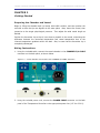
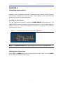
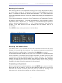
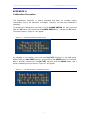
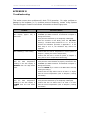
TEMPERATURE CONTROLLER
USER’S MANUAL
TC-09S / TC-09D User’s Manual
DOC-226
Rev. 1.2
Copyright © 2009
All Rights Reserved
LIVING SYSTEMS INSTRUMENTATION
TC-09 TEMPERATURE CONTROLLER
THIS PAGE INTENTIONALLY LEFT BLANK
- ii -
LIVING SYSTEMS INSTRUMENTATION
TC-09 TEMPERATURE CONTROLLER
TABLE OF CONTENTS
Chapter 1 .............................................................................................. 1
Introduction ...................................................................................................... 1
Compatible Vessel Chamber Models ................................................................... 1
Specifications ................................................................................................. 1
Front and Back Panels ..................................................................................... 2
Chapter 2 .............................................................................................. 3
Getting Started .................................................................................................. 3
Preparing the Chamber and Vessel .................................................................... 3
Wiring Instructions .......................................................................................... 3
Chapter 3 .............................................................................................. 4
Operating Instructions ........................................................................................ 4
Turning on the Power ...................................................................................... 4
Making Menu Selections ................................................................................... 4
Using the TC-09 for Temperature Monitoring....................................................... 5
Setting the Control Temperature ....................................................................... 6
Setting the Alarms .......................................................................................... 7
Running the Controller ..................................................................................... 8
Resetting the Audible Alarm.............................................................................. 8
Completing an Experiment................................................................................ 8
Appendix A ............................................................................................ 9
Calibration Procedure ......................................................................................... 9
Appendix B .......................................................................................... 12
Troubleshooting............................................................................................... 12
- iii -
LIVING SYSTEMS INSTRUMENTATION
TC-09 TEMPERATURE CONTROLLER
CHAPTER 1
Introduction
The Living Systems Instrumentation Temperature Controller is designed to set and
control the temperature of the non-superfused baths in Living Systems Instrumentation
vessel chambers that are equipped with heating elements and thermistor temperature
probes. The Temperature Controller can also be used as a bath thermometer, displaying
the bath temperature without heating.
The Temperature Controller allows the user to enter the desired Set Point, as well as
High and Low Alarm Points. The Temperature Controller emits an audible alarm if the
bath temperature is outside of these limits.
Compatible Vessel Chamber Models
TC-09S Single Channel Temperature Controller:
CH-1-H
TC-09D Dual Channel Temperature Controller:
CH-2-H
Specifications
Chamber Bath Temperature:
Control Range:
Regulation:
Accuracy:
Readout Resolution:
25 to 50 °C
± 1.0 °C from 32 to 35°C
± 1.0 °C from 32 to 35°C
0.1 °C
Probe Sensor:
Custom LSI thermistor
Display:
4-line LCD. Temperature updated every second
Power:
117 V / 60 Hz or 220 V / 50 Hz (as specified)
Size:
22.5 x 7.5 x 17.5 cm (L x H x W) (8.86 x 2.95 x 6.89 in)
Weight:
1.25 kg (2.75 lbs)
- 1 -
LIVING SYSTEMS INSTRUMENTATION
TC-09 TEMPERATURE CONTROLLER
Front and Back Panels
Figure 1.1 – TC-09D Front Panel
Figure 1.2 - TC-09D Dual ChamberTemperature Controller Back Panel
Figure 1.3 - TC-09S Single Chamber Temperature Controller Back Panel
- 2 -
LIVING SYSTEMS INSTRUMENTATION
TC-09 TEMPERATURE CONTROLLER
CHAPTER 2
Getting Started
Preparing the Chamber and Vessel
Begin by filling the chamber bath (or baths) with buffer solution, and then position the
cannulas so that the tips are aligned on the same plane. Next, mount the vessel, then
pressurize to the target physiological pressure. Then adjust the axial vessel length as
desired.
Position the thermistor tip so that it is as close as possible to the vessel, minimizing the
difference between the controlled temperature and vessel temperature due to the
inherent temperature gradients within the bath. Also, be sure that the thermistor tip is
completely submerged.
Wiring Instructions
1. Using the included cable, connect the vessel chamber to the CHAMBER I/O CABLE
connector on the back panel, as shown below.
Figure 2.1 – Vessel Chamber Connected to the CHAMBER I/O CABLE Connector
2. Using the included power cord, connect the POWER CABLE connector on the back
panel of the Temperature Controller to the appropriate power line (117 V or 220 V).
- 3 -
LIVING SYSTEMS INSTRUMENTATION
TC-09 TEMPERATURE CONTROLLER
CHAPTER 3
Operating Instructions
Operation of the Temperature Controller is achieved through the use of the LCD screen
and the three pushbuttons on the front panel. Menus appear on the LCD screen and
selections are made using the pushbuttons.
Turning on the Power
Turn the Temperature Controller on using the POWER SWITCH on the back panel. The
POWER SWITCH will be illuminated, the internal fan will turn on and the Main Menu will
appear on the LCD. Allow the Temperature Controller to warm up for at least two
minutes prior to running.
Figure 3.1 – TC-09D Main Menu with Set Temperature Highlighted
NOTE: The Chamber Select menu option appears only on the TC-09D Main Menu.
Making Menu Selections
Use the UP and DOWN arrows keys to scroll through the menu items. Press the ENTER
key to select the highlighted menu item.
- 4 -
LIVING SYSTEMS INSTRUMENTATION
TC-09 TEMPERATURE CONTROLLER
Using the TC-09 for Temperature Monitoring
The TC-09 can also be used as a bath thermometer. When the TC-09 is functioning as a
thermometer, the bath(s) will not be heated.
TC-09D
Select Chamber Select from the Main Menu. The screen shown in Figure 3.2 will
appear. Select the chambers to heat and press the ENTER button to save the selection
and return to the main menu. The Heat No Chambers option monitors the temperature
in both chambers without heating.
Figure 3.2 – TC-09D Chamber Select Menu
Figure 3.3 - Dual Vessel Chamber with Chamber 1 and Chamber 2 Indicated
- 5 -
LIVING SYSTEMS INSTRUMENTATION
TC-09 TEMPERATURE CONTROLLER
TC-09S
Select Chamber On/Off from the Main Menu. The screen shown in Figure 3.2 will
appear. Select whether or not to heat the chamber and press the ENTER button to save
the selection and return to the main menu.
Figure 3.4 – TC-09S Chamber On/Off Menu
Setting the Control Temperature
Set the desired vessel temperature to be controlled by selecting Set Temperature from
the Main Menu. The LCD will display the current control temperature, as shown in Figure
3.5.
The Set Control Temperature menu displays the previously set Control Temperature. Use
the UP and DOWN keys to adjust this temperature in one degree increments within the
range of 25 to 50 °C. When the desired control temperature is reached, press ENTER to
store this value.
The TC-09S will return the Main Menu after pressing ENTER, and the TC-09D will prompt
the user to set the Chamber 2 Control Temperature. Set the Chamber 2 Control
Temperature in the same manner that the Chamber 1 Control Temperature was set, then
press ENTER to store this value and return to the Main Menu.
Figure 3.5 – TC-09S Set Control Temperature Menu
- 6 -
LIVING SYSTEMS INSTRUMENTATION
TC-09 TEMPERATURE CONTROLLER
Setting the Alarms
NOTE: The alarm values are the same for both chambers when using the TC-09D.
Once the bath temperature is reached, the Temperature Controller will emit an audible
alarm if the bath temperature exceeds the High Alarm or drops below the Low Alarm.
To set the High and Low Alarm values, select Set Alarms from the Main Menu.
screen shown in Figure 3.6 will appear.
The
The Set High Alarm menu displays the previously set High Alarm. Use the UP and
DOWN keys to adjust this temperature in one degree increments within the range of 28
to 50 °C. It is recommended that the High Alarm be set to a temperature 2 °C higher
than the control temperature. When the desired temperature is reached, press ENTER
to store this value. The screen shown in Figure 3.7 will appear.
Figure 3.6 - Set High Alarm Menu
The Set Low Alarm menu displays the previously set Low Alarm. Use the UP and DOWN
keys to adjust this temperature in one degree increments within the range of 25 to 45
°C. It is recommended that the Low Alarm be set to a temperature 2 °C lower than the
control temperature. When the desired temperature is reached, press ENTER to store
this value and return to the Main Menu.
Figure 3.7 – Set Low Alarm Menu
- 7 -
LIVING SYSTEMS INSTRUMENTATION
TC-09 TEMPERATURE CONTROLLER
Running the Controller
After verifying that all of the temperature settings (Control, High Alarm and Low Alarm)
are correct, begin running the Temperature Controller by selecting Run from the Main
Menu. The display will indicate the present bath temperature. The TC-09S will display a
single bath temperature and the TC-09D will simultaneously display the temperatures of
both baths.
If the present temperature is below the Control Temperature, the Temperature Controller
will begin to heat the bath(s). It will take approximately six to ten minutes to reach a
temperature within a degree of 37 °C. However, up to 20 minutes may be required to
attain a stabilized temperature within ± 1 °C or better because of heat convection
currents in the bath solution and heat exchange from the chamber base to its
surroundings.
Press ENTER to stop running and return to the Main Menu.
Figure 3.8 – TC-09D Run Display
Resetting the Audible Alarm
The audible alarm is not activated until the bath temperature enters the limit range
(between the Low and High Alarm settings). Any subsequent temperatures outside these
limits will result in an audible alarm. Press and hold the DOWN key to reset it.
If the audible alarm does sound, do not ignore it, as its purpose is to protect the tissue
and the instrument. For example, during lengthy experiments, the bath level can fall due
to evaporation so that the temperature probe is no longer immersed. The temperature
measure may then fall below the Low Alarm value, causing an audible alarm. Although
pressing the DOWN key will reset the alarm, additional buffer solution should promptly
be added to the bath so that the experiment can be continued.
Completing an Experiment
When an experiment has reached completion, press the ENTER key to return to the Main
Menu and turn off the heater(s). All of the menu selections made prior to running the
experiment are retained in memory when the power is turned off, allowing a new
experiment to be started without making any changes to these selections.
- 8 -
LIVING SYSTEMS INSTRUMENTATION
TC-09 TEMPERATURE CONTROLLER
APPENDIX A
Calibration Procedure
The Temperature Controller is factory calibrated and does not normally require
recalibration, even if the thermistor is changed. However, the user may recalibrate if
necessary.
To calibrate the Temperature Controller, turn the POWER SWITCH off, then press and
hold the UP button while switching the POWER SWITCH on. Release the UP button.
The screen shown in Figure A.1 will appear.
Figure A.1 – Entering Calibration Mode Screen
As indicated on the display, press and hold CAL/TEST button(s) on the back panel.
While holding the CAL/TEST button(s), press and hold the ENTER button for 3 seconds.
After 3 seconds, release both the CAL/TEST button(s) and the ENTER button, and a
screen resembling the one shown in Figure A.2 will appear.
Figure A.2 – TC-09D Chamber 1 Calibration Screen
- 9 -
LIVING SYSTEMS INSTRUMENTATION
TC-09 TEMPERATURE CONTROLLER
Next, connect a digital voltmeter equipped with a BNC connector to the ANALOG TEMP
OUTPUT connector on the back of the Temperature Controller (CHAMBER 1 on the TC09D) to measure the DC output, as shown below.
Figure A.3 - Connecting a Voltmeter to the ANALOG TEMP OUTPUT
As indicated on the back panel of the TC-09, 10 mV is equivalent to 0.1 °C. The
Temperature Controller should be calibrated to 37.0 °C, therefore the desired voltage
reading on the digital voltmeter is 3.70 VDC. If necessary, adjust the DC output using
the UP and DOWN buttons until it is as close as possible to 3.70 VDC.
Figure A.4 - Use the UP or DOWN Arrow Buttons to Adjust the Output Voltage to 3.70 VDC
- 10 -
LIVING SYSTEMS INSTRUMENTATION
TC-09 TEMPERATURE CONTROLLER
Press ENTER to set the calibration value. The TC-09S will return the Main Menu after
pressing ENTER, and the TC-09D will prompt the user to Read Analog Temp 2. Connect
the digital voltmeter to the CHAMBER 2 ANALOG TEMP OUTPUT connector and repeat
the calibration procedure in the same manner as Chamber 1. Then press ENTER to set
the calibration value and return to the Main Menu.
- 11 -
LIVING SYSTEMS INSTRUMENTATION
TC-09 TEMPERATURE CONTROLLER
APPENDIX B
Troubleshooting
This section covers minor problems with basic TC-09 operation. For major problems or
damage to the hardware, or if a problem reoccurs frequently, contact Living Systems
Technical Support. Please find all contact information at www.livingsys.com.
Problem
Corrective Action
The bath temperature on the
Run Display (Figure 3.8) is
inaccurate.
• Verify that the chamber is properly connected to the
CHAMBER I/O CABLE connector as described in Chapter 2,
Wiring Instructions;
• Verify that the thermistor tip is completely submerged;
• With the controller in Run Mode, press the CAL/TEST
button(s). The Bath Temp should be 37.0 °C. If it is not,
perform the calibration procedure in Appendix A. If the
Bath Temp is 37.0 °C, the thermistor may need to be
replaced.
The chamber(s) is not heating.
• Confirm that the Control Temperature is correct (Refer to
Chapter 3, Setting the Control Temperature;
• Confirm that the heat is turned on (Refer to Chapter 3,
Using the TC-09 for Temperature Monitoring).
The Audible Alarm is sounding
and
the
bath
temperature
reading on the Run Display is
HIGHER than the High Alarm
Limit.
• Press and hold the DOWN key to reset the alarm;
• Verify that the vessel chamber is properly connected to the
CHAMBER I/O CABLE connector as described in Chapter 2,
Wiring Instructions;
• Press the ENTER key to return to the Main Menu and stop
heating the bath(s);
• Confirm that the High Alarm Limit is at least 2 °C higher
than the control temperature (refer to Chapter 3, Setting
the Alarms).
The Audible Alarm is sounding
and
the
bath
temperature
reading on the Run Display is
LOWER than the Low Alarm
Limit.
• Press and hold the DOWN key to reset the alarm;
• Verify that the thermistor tip is completely submerged;
• Confirm that the Low Alarm Limit is at least 2 °C lower
than the control temperature (refer to Chapter 3, Setting
the Alarms).
- 12 -