1
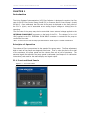
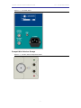
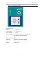
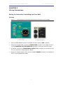
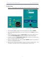
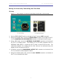
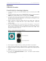
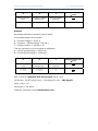
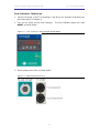
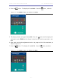
FLOW INDICATOR
USER’S MANUAL
FI-1 User’s Manual
DOC-230
Rev. 1.1
Copyright © 2010
All Rights Reserved
www.livingsys.com
LIVING SYSTEM INSTRUMENTATION
FI-1 FLOW INDICATOR
THIS PAGE INTENTIONALLY LEFT BLANK
- ii -
LIVING SYSTEM INSTRUMENTATION
FI-1 FLOW INDICATOR
TABLE OF CONTENTS
Chapter 1 .............................................................................................. 1
Introduction ...................................................................................................... 1
Principles of Operation..................................................................................... 1
FI-1 Front and Back Panels ............................................................................... 1
Compatible Infusion Pumps .............................................................................. 2
Specifications ................................................................................................. 3
Chapter 2 .............................................................................................. 4
Wiring Instructions............................................................................................. 4
Wiring for Internally Controlling the Flow Rate .................................................... 4
Wiring for Externally Controlling the Flow Rate .................................................... 6
Chapter 3 .............................................................................................. 8
Calibration Procedure ......................................................................................... 8
FC and PS-200-P (in Flow Mode) Calibration........................................................ 8
Flow Indicator Calibration .............................................................................. 10
Chapter 4 ............................................................................................ 13
Operating Instructions ...................................................................................... 13
Living Systems Contact Information .................................................... 14
- iii -
LIVING SYSTEM INSTRUMENTATION
FI-1 FLOW INDICATOR
CHAPTER 1
Introduction
The Living Systems Instrumentation (LSI) Flow Indicator is designed to monitor the flow
rate of the LSI Flow Control Pump (model FC) or Pressure Servo Control Pump* (model
PS-200-P). Once calibrated, the flow rate of the pump is displayed on the front panel of
the FI-1 in μl/min, and is accessible as an analog output voltage at 10mV/μl/min for
recording.
The flow rate of the pump may also be controlled via an external voltage applied to the
EXTERNAL FLOW INPUT connector on the back of the FI-1. The voltage (0.0 to +9.9
VDC) applied to the FI-1 EXTERNAL FLOW INPUT connector is routed into the pump to
control the flow rate.
*Note: Pressure Servo Control Pumps purchased before 1998 require a modest modification.
Principles of Operation
The volume of flow is proportional to the speed of the pump motor. The flow adjustment
dials on each of the pumps are designed to be linear. That is, when the dial is set to half
of the maximum, the pump speed and the volume flow are at half of maximum. The
electrical signal that monitors the pump speed is calibrated (see Chapter 3 for calibration
instructions) and used for the meter display and signal output.
FI-1 Front and Back Panels
Figure 1.1 – FI-1 Front Panel
- 1 -
LIVING SYSTEM INSTRUMENTATION
FI-1 FLOW INDICATOR
Figure 1.2 – FI-1 Back Panel
Compatible Infusion Pumps
Figure 1.3 – FC Flow Control Pump Front Panel
- 2 -
LIVING SYSTEM INSTRUMENTATION
FI-1 FLOW INDICATOR
Figure 1.4 – PS-200-P Pump Front Panel
Specifications
Range:
0 – 2,500 μl/min
Output Updated:
> 40 updates/second
Meter Resolution:
± 0.1 μl/min
Power Requirements: 100 – 120 VAC / 60 Hz or 200 – 240 VAC / 50 Hz
Auto detected and selected internally
Power Consumption: 5 watts
Maximum Amperage: 1 Amp
Fuse Type:
1 Amp, GMC Type, Medium Time Delay
Physical Size:
5.25 H x 4.25 W x 6 L in / 13 H x 11 W x 15 L cm
Weight:
1.5 lbs / 0.7 kg
- 3 -
LIVING SYSTEM INSTRUMENTATION
FI-1 FLOW INDICATOR
CHAPTER 2
Wiring Instructions
Wiring for Internally Controlling the Flow Rate
FC Pump
Figure 2.1 – Wiring Diagram for Internally Controlling the Flow Rate of the FC Pump
1. Set the SPEED SOURCE switch on the back of the FC pump to INT (internal).
2. Using the included cable, connect the FROM PUMP connector on the back of the FI1 to the MONITOR OUT/EXT SPEED IN connector on the back of the FC pump.
3. If desired, connect the FLOW SIGNAL OUTPUT BNC connector on the back of the
FI-1 to a recorder or data acquisition device.
4. Using the included power cord, connect the A/C POWER connector on the back of
the FI-1 to a standard wall outlet.
- 4 -
LIVING SYSTEM INSTRUMENTATION
FI-1 FLOW INDICATOR
PS-200-P Pump
Figure 2.2 – Wiring Diagram for Internally Controlling the Flow Rate of the PS-200-P Pump
1. Set the FLOW CONTROL switch on the back of the PS-200-P pump to NORMAL.
2. Set the FLOW/PRESSURE switch on the front of the PS-200-P to FLOW, as shown in
Figure 1.4.
3. Using the included cable, connect the FROM PUMP connector on the back of the FI1 to the TO FLOW INDICATOR connector on the back of the PS-200-P pump.
4. If desired, connect the FLOW SIGNAL OUTPUT BNC connector on the back of the
FI-1 to a recorder or data acquisition device.
5. Using the included power cord, connect the A/C POWER connector on the back of
the FI-1 to a standard wall outlet.
6. Referring to the PS-200 User’s Manual, connect the PS-200-P to the PS-200-S. This
connection is important, as the PS-200-S supplies power to the PS-200-P.
- 5 -
LIVING SYSTEM INSTRUMENTATION
FI-1 FLOW INDICATOR
Wiring for Externally Controlling the Flow Rate
FC Pump
Figure 2.3 – Wiring Diagram for Externally Controlling the Flow Rate of the FC Pump
1. Set the SPEED SOURCE switch on the back of the FC pump to EXT (external).
2. Using the included cable, connect the FROM PUMP connector on the back of the FI1 to the MONITOR OUT/EXT SPEED IN connector on the back of the FC pump.
3. Using a BNC cable, connect the EXTERNAL FLOW INPUT connector on the back of
the FI-1 to a voltage source. The voltage (0.0 to +9.9 VDC) applied to the FI-1
EXTERNAL FLOW INPUT is routed into the FC pump to control the flow rate. The
relationship between the voltage and the flow rate can be monitored using the
display on the front panel of the FI-1.
4. If desired, connect the FLOW SIGNAL OUTPUT BNC connector on the back of the
FI-1 to a recorder or data acquisition device.
5. Using the included power cord, connect the A/C POWER connector on the back of
the FI-1 to a standard wall outlet.
- 6 -
LIVING SYSTEM INSTRUMENTATION
FI-1 FLOW INDICATOR
PS-200-P Pump
Figure 2.4 – Wiring Diagram for Externally Controlling the Flow Rate of the PS-200-P Pump
1. Set the FLOW CONTROL switch on the back of the PS-200-P pump to EXTERNAL.
2. Set the FLOW/PRESSURE switch on the front of the PS-200-P to FLOW, as shown in
Figure 1.4.
3. Using the included cable, connect the FROM PUMP connector on the back of the FI1 to the TO FLOW INDICATOR connector on the back of the PS-200-P pump.
4. Using a BNC cable, connect the EXTERNAL FLOW INPUT connector on the back of
the FI-1 to a voltage source. The voltage (0.0 to +9.9 VDC) applied to the FI-1
EXTERNAL FLOW INPUT is routed into the PS-200-P pump to control the flow rate.
The relationship between the voltage and the flow rate can be monitored using the
display on the front panel of the FI-1.
5. If desired, connect the FLOW SIGNAL OUTPUT BNC connector on the back of the
FI-1 to a recorder or data acquisition device.
6. Using the included power cord, connect the A/C POWER connector on the back of
the FI-1 to a standard wall outlet.
7. Referring to the PS-200 User’s Manual, connect the PS-200-P to the PS-200-S. This
connection is important, as the PS-200-S supplies power to the PS-200-P.
- 7 -
LIVING SYSTEM INSTRUMENTATION
FI-1 FLOW INDICATOR
CHAPTER 3
Calibration Procedure
FC and PS-200-P (in Flow Mode) Calibration
1.
If using the FC pump, set the SPEED SOURCE switch on the back panel to INT
(internal).
2.
If using the PS-200-P pump, set the FLOW/PRESSURE switch on the front panel to
FLOW and the FLOW CONTROL switch on the back panel to NORMAL.
3.
Load a tube set into the pump and connect the inflow tube to a solution reservoir. If
the tube set has never been used before, run the pump at full speed for 20-30
minutes to allow the tubing to stretch.
4.
Select a container to collect the effluent fluid from the outflow tube. Weigh the
empty container on a digital scale with 1 mg or better resolution. Record the
container weight.
5.
Set the flow adjustment knob on the pump to 90% of the maximum. If using the FC
pump, the coarse adjustment should be set to 90 and the fine adjustment should be
set to 0, and on the PS-200-P the Flow Adjust knob should be set to 9.0. These
settings are illustrated in Figure 3.1.
Figure 3.1 – Flow Controls Set to 90% of Maximum
6.
Run the pump for at least 15 minutes, collecting the effluent in the container.
7.
At the end of the timed infusion, weigh the container. Record the container weight.
8.
Subtract the weight of the empty container from the weight of the container plus the
effluent.
9.
Divide the difference by the duration of the infusion (in minutes).
10. The result is the Calibrated Flow Rate in μl/min. This value is used to calibrate
the FI-1 Flow Indicator.
- 8 -
LIVING SYSTEM INSTRUMENTATION
FI-1 FLOW INDICATOR
A
B
T
Container Weight
(mg)
Container + Effluent
Weight (mg)
Infusion Duration
(minutes)
Calibrated Flow Rate
(μl/min)
B – A
T
Example
An example calibration procedure is shown below.
If the measurements are as follows:
A = Container Weight = 29.327 g
B = Container + Effluent Weight = 33.543 g
T = Infusion Duration in minutes = 15
Then the first step is to convert grams to milligrams:
A = (29.327 g)(1000 mg/g) = 29,327 mg
B = (33.543 g)(1000 mg/g) = 33,543 mg
Calibrated Flow Rate
A
B
T
Container Weight
(mg)
Container + Effluent
Weight (mg)
Infusion Duration
(minutes)
B – A
29,327
33,543
15
281
(μl/min)
T
Now, to find the calibrated flow rate (µl/min) use (B – A)/T
(33,543 mg – 29,327 mg)/(15 min) = (4,216 mg)/(15 min) = 281 mg/min
Using, 1 mg = 1 µl
281 mg/min = 281 µl/min
Therefore, 281 µl/min is the calibrated flow rate.
- 9 -
LIVING SYSTEM INSTRUMENTATION
FI-1 FLOW INDICATOR
Flow Indicator Calibration
1. Connect the pump to the FI-1 according to the Wiring for Internally Controlling the
Flow Rate section of Chapter 2.
2.
Turn on the pump and the Flow Indicator.
RESET, as shown below.
The Flow Indicator display will read
Figure 3.2 – Turn on the FI-1 and the Display Reads RESET
3. Set the pump to zero flow, as shown below.
Figure 3.3 - Flow Controls Set to Zero
- 10 -
LIVING SYSTEM INSTRUMENTATION
4. Press the
FI-1 FLOW INDICATOR
button. The display will read Lo In. Press the
button, as shown.
Figure 3.4 – Press MENU, Display Says Lo In, Press PEAK
5. The display should read approximately 0.0. Press the
button and the display will
momentarily read STORE as this voltage is stored as that which corresponds to zero
flow.
6. Once again, set the flow adjustment knob on the pump to 90% of the maximum, as
shown in Figure 3.1.
7. Press the
button. The display will read Hi In. Press the
Figure 3.5 – Press MENU, Display Says Hi In, Press PEAK
- 11 -
button, as shown.
LIVING SYSTEM INSTRUMENTATION
FI-1 FLOW INDICATOR
8. The display now shows the voltage that corresponds to this pump speed. Press the
button and the display will momentarily read STORE as this voltage is stored as
that which corresponds to the calibrated flow.
9. Press the
button. The display will read Lo rd (low reading). Press the
button
and the current flow rate of 0.0 μl/min will be displayed.
button again and the display will read Hi rd (high reading). This value
10. Press the
must be set to the Calibrated Flow Rate determined in the FC and PS-200-P (in
Flow Mode) Calibration procedure above. Press the
digit on the display. Using the
the
button to highlight the first
button, set this to the correct digit, and then press
button again to highlight the next digit to the right. Repeat using these two
buttons to set the third digit.
11. Once the Calibrated Flow Rate is on the display, press the
button several times
until the display reads RESET. The calibration is now complete and the display on
the FI-1 will show the infusion rate in μl/min.
12. The calibration information will be retained when the FI-1 is turned off. Therefore,
as long as the tubing set has not been changed, the flow reading will be correct when
the instrument is turned on again. The calibration procedure should be repeated
periodically and whenever the tubing set is changed.
- 12 -
LIVING SYSTEM INSTRUMENTATION
FI-1 FLOW INDICATOR
CHAPTER 4
Operating Instructions
Operation of the FI-1 Flow Indicator is achieved using the display and the four
pushbuttons on the front panel. Menus appear on the display and selections are made
using the pushbuttons.
Connect the FI-1 to the pump according to the directions outlined in Chapter 2 of this
manual. If necessary, perform the calibration procedure outlined in Chapter 3 of this
manual.
Turn on the FI-1 using the ON/OFF switch on the front panel. The screen will display
RESET momentarily, as shown in Figure 3.2, and then it will display the flow rate in
μl/min.
If the value on the display is incorrect, verify that the pump is turned on and connected
properly.
- 13 -
LIVING SYSTEM INSTRUMENTATION
FI-1 FLOW INDICATOR
LIVING SYSTEMS CONTACT INFORMATION
Please feel free to contact the staff at Living System Instrumentation at any time.
Living Systems Instrumentation, Inc .
A division of Catamount Research & Development
802.863.5547 . 802.863.8057 (fax) . [email protected] . www.livingsys.com
- 14 -