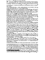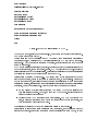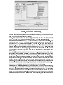
1
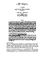
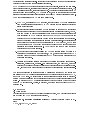
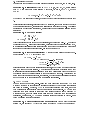
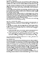
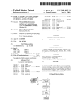
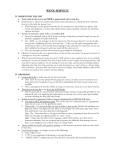
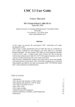
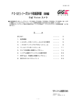
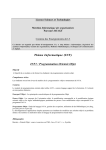
Centrum voor Wiskunde en Informatica
REPORTRAPPORT
The Integration Project for the JACK Environement
Amar Bouali, Stefania Gnesi, Salvatore Larosa
Computer Science/Department of Software Technology
CS-R9443 1994
The Integration Project
for the JACK Environment
Amar Bouali
CWI
P.O. Box 94079, 1090 GB Amsterdam, The Netherlands
[email protected]
Stefania Gnesi
Salvatore Larosa
IEI-CNR
via Santa Maria, 46 I-56100 Pisa, Italy
fgnesi,[email protected]
Abstract
JACK, standing for Just Another Concurrency Kit, is a new environment integrating a set of verication
tools, supported by a graphical interface oering facilities to use these tools separately or in combination.
The environment proposes several functionalities for the design, analysis and verication of concurrent
systems specied using process algebra. Tools exchange information through a text format called Fc2.
Users are able to graphically layout their specications, that will be automatically converted into the
Fc2 format and then minimised with respect to various kinds of equivalences. A branching time and
action based logic, ACTL, is used to describe the properties that the specication must satisfy, and model
checking of ACTL formulae on the specication is performed in linear time. A translator from Natural
Language to ACTL formulae is provided, in order to simplify the job to describe the specication properties
by ACTL formulae. A description of the graphical interface is given together with its functionalities and
the exchange format used by the tools. As an example of use of JACK, we present a small case study
within JACK, that covers both verication of a software system and verication of its properties.
AMS Subject Classication (1991): 68N99, 68Q10, 68Q22, 68Q60.
CR Subject Classication (1991): D.2.2, D.2.4, D.2.6, F.1.1, F.3.1.
Keywords & Phrases: Specication tools, verication tools, reactive systems, integrated environment,
methodology, bisimulation, model checking.
Note: The rst author started this work while visiting the Istituto di Elaborazione dell'Informazione of
CNR in Pisa and was funded by the European Research Consortium for Informatics and Mathematics,
fellowship programme. The other authors were funded by the LAMBRUSCO project, supported by the
CNR Finalized Project for Information Systems and Parallel Computation, unita operativa IEI { University
La Sapienza, Rome.
1. Introduction
When the verication of system properties is an important issue, automatic tools are
needed. Some verication environments are now available which can be used to verify
properties of reactive systems, specied by means of terms belonging to process algebrae and modelled by means of nite state Labelled Transition Systems (automata), with
respect to behavioural relations and logical properties 4, 9, 28, 38, 20, 18].
Recently a new verication environment, JACK, 10] was dened to deal with reactive
sytems. The purpose of JACK is to provide a general environment that oers a series
of functionalities, ranging from the specication of reactive systems to the verication of
behavioural and logical properties. It has been built beginning with a number of separately
developed tools that have been successively integrated.
JACK covers much of the formal software development process, including the formalization of requirements 17], rewriting techniques 12], behavioural equivalence proofs 22, 14],
graph transformations 19], logic verications 11]. The logical properties are specied by
an action based temporal logic, ACTL dened in 14], wich is highly suitable to express
safety and liveness properties of reactive systems modelled by Labelled Transition Systems.
The main functionalities of JACK are summarized below.
1. NL2ACTL, a generator of ACTL formulae, that produces an ACTL formula starting
from a natural language sentence: NL2ACTL helps in the formalization of informal
systems requirements
2. Behavioural equivalence verication by both rewriting on terms and on equivalence
algorithms for nite state LTS: a process algebra term rewriting laboratory, Crlab,
that can be used to prove equivalences of terms through equational reasoning has
been integrated in JACK together with the Auto/Mauto/Autograph tool set
developed at INRIA these tools can be used for the automatisation of the specication and verication of process algebra terms in nite state cases. Specications are
given following the syntax of some process algebra (Auto/Mauto), or by means
of a graphical tool (Autograph) that allows the user to draw automata that are
translated into process algebra terms. Auto/Mauto can then be used for formal
verication and automata analysis.
3. Model checking of properties expressed in ACTL on a reactive system modelled by a
nite state LTS: a linear time model checker, AMC, for the action based logic ACTL
has been dened to prove the satisability of ACTL formulae and consequently the
properties of systems.
4. Analysis of concurrent systems with respect to various concurrency semantics (interleaving, partial order, multiset...): a parametric tool, the PisaTool, has been
developed that allows the user to observe many dierent aspects of a distributed system, such as the temporal ordering of events and their causal and spatial relations.
The paper is organized as follows: Section 2 presents an overview of the syntax and
semantics of the CCS/Meije process algebra used to describe reactive sytems in JACK,
and of the ACTL logic. An introduction to formal verication tools is given in Section 3.
Section 4 gives a description of the integration project and the graphical interface of the
system. In Section 5 the JACK interface is described (with an overview of the components
of the JACK environment). Finally, in Section 6, we give an example of use of the JACK
environment.
2. Background
2.1 Preliminaries
We rst introduce the concept of Labelled Transition System, on which reactive systems
are modelled and ACTL formulae are interpreted,
Denition 2.1 (Labelled Transition System) A Labelled Transition System is a 4tuple
A = (Q q0 Act f g R), where:
Q is a nite set of states. We let q r s : : : range over states
q0 is the initial state
Act is a nite set of observable actions and is the unobservable action. We let
a b : : : range over Act, and : : : range over Act f g
R Q Act f g Q is the transition relation.
ut
Note 2.2 For A Act, we let A denote the set A f g.
For A Act , we let RA (q ) denote the set fq : there exists 2 A such that (q q ) 2 Rg.
0
0
We will also use the action name, instead of the corresponding singleton denotation, as
subscript. Moreover, we use R(s) to denote RAct (s).
q
For A B Act , we let A=B denote the set A ; (A \ B ). Often, we simply write q ;!
for (q q ) 2 R
ut
0
0
Denition 2.3 Given an LTS A = (Q q0 Act f g R), we have that:
a path in A is a nite or innite sequence q1 q2 : : : of states, such that qi+1 2 R(qi).
The set of paths starting from a state q is denoted by (q ). We let : : : range
over paths
0
a path 2 (q) is called maximal if it is innite or if it is nite and its last state q
has no successor states (i.e. R(q ) = )
if is innite, then we dene jj = ! if = q1 q2 : : : qn, then we dene jj = n;1.
Moreover, if j j i ; 1 , we will denote by (i) the ith state in the sequence.
ut
0
0
2.2 Process Algebrae
Process algebrae are syntaxes for the description of parallel and communicating processes.
Here we give a brief presentation of CCS/Meije process algebra, 1, 7], which is used by
the JACK system for the description of reactive systems. For simplicity, we describe the
subset of Meije that corresponds to the CCS process algebra, following R. Milner 31].
Moreover, we adopt the syntax used in the Auto/Mauto tools (see section 5) and restrict
it to their rules to guarantee the satisability of some nitary conditions of the underlying
semantic model, namely automata 15].
The Meije Syntax: The Meije syntax is based on a set of actions that processes can
perform and on a set of operators expressing process behaviors and process combinations.
The Auto/Mauto CCS/Meije syntax permits a two { layered design of process terms:
the rst level is related to the sequential regular process description the second to a
network of parallel sub-processes, supporting communication and action visibility lters.
The syntax starts from a set of labels Act as atomic signal names ranged over by alphanumeric strings such names represent emitted signals if they are terminated by the "!"
character, or received ones if they are terminated by "?". denotes the special action not
belonging to Act, symbolising the unobservable action (to model internal process communications) we let Act = Act f g to denote the full set of actions that a process can
perform.
The following syntax is related to the denition of regular sequential processes: R denotes
a sequential process, while a matches any element of Act X is a label denoting a process
variable
R ::= stop j a : R j R + R j
let rec fX = R and X = R ] g in X
Here, : : :] denotes an optional and repeatable part of the syntax. We now explain the
CCS/Meije sequential part semantics:
stop is the process without behavior
a : R is the action prex operator
X = R bounds the process variable X to the process R
R + R is the non deterministic choice operator.
The let rec construct allows recursive denitions of process variables.
The second level of process term denition is used to design networks of parallel sub
components denoted here by P , where R is a sequential regular process:
P ::= R j P k P j P n a j P a=b] j a P j
let fX = P and X = R ] g in X
k is the parallel operator
P n a is the action restriction operator, meaning that a can only be performed within
a communication
P a=b] is the substitution operator, renaming b into a.
a P is the ticking operator, driving process P by performing action a simultaneously
with any behavior of P . This means that any time that process P performs an action,
then process a P performs in parallel both this action and action a.
The let construct bounds non recursive denitions of process variables.
The Figure 0.1 shows the structural operational semantics of some CCS/Meije operators previously described, in terms of labelled transition systems 34]: note that the
CCS/Meije parallel operator operational rules are those of the CCS parallel operator,
whereas the Meije parallel operator, instead, has an additional rule allowing product of
actions that are not necessarily co{names (i.e. a! and a?).
Operator
a:P
Operational rules
a P
a : P ;!
a Q
Q ;!
P +Q
a Q
P + Q ;!
a Q
a P
a? P Q ;!
a! Q
Q ;!
P
;!
P
;!
P k Q P k Q ;!
a P kQ
a P kQ
P k Q ;!
P k Q ;! P k Q
Figure 0.1: Operational semantics of some Meije operators
a P
P ;!
a P
P + Q ;!
0
0
0
0
0
0
0
0
0
0
0
0
2.3 Bisimulation Semantics
We give here the denition of the bisimulation equivalence over LTSs, due to Park, 33].
Denition 2.1 (Bisimulation) Given an LTS A = (Q q0 Act f g R), a bisimulation
over Q Q is a binary symmetric relation R such that, for any (p q ) 2 Q Q, we have
pRq i:
p ) (9q q ;!
q ^ p Rq ))
8 2 Act (p ;!
0
0
0
0
0
We note by the largest such relation, that is the union of all bisimulations denable over
S.
Observational bisimulations, rst introduced by Milner 31], are dened through the notion
of an unobservable action , considered as a silent step in the system behavior. To abstract
unobservable moves during observation, we shall use the weak transition relation dened
as follows:
Denition 2.2 (The Weak Relation)
" def
=)
= (;!)?
a def
" ;!
a =)
"
8a 2 Act =)
= =)
Weak bisimulation is then dened upon this relation, and called the weak ;!. We denote
the largest one by . Branching bisimulation, rst introduced in 39] and denoted byb ,
is a particular observational bisimulation rening the notion of unobservable moves taking
into account the internal nondeterminism. Its scheme is given by:
Denition 2.3 (Branching Bisimulation) A branching bisimulation is a binary symmetric relation R Q Q such that pRq i:
p )
8 2 Act (p ;!
( = ^ p Rq ) or (9q1 : : : qn such that
q and
(1) q = q1 ;! ;! qn ;!
(2) 8i 2 1 : : :n] pRqi p Rq )
0
0
0
0
0
Bisimulations are used to minimise transition systems, as they dene a minimal canonical
form, and also to compare systems. Two systems are considered equivalent if and only
if their respective initial states are related within some bisimulation over the product of
the disjoint union of the sets of states of the two systems to compare. Verication with
automata widely uses these concepts, for instance, to check partial properties of systems
and to compare an implementation with a particular specication.
2.4 The ACTL Logic
We now dene the temporal, action{based and pure branching time logic ACTL 14]
a logic of this type is appropriate to express properties of LTSs because its operators
are based on actions. Moreover, ACTL is a temporal branching time logic, as it has
both operators for quantication over paths and linear time operators. ACTL is a pure
branching time logic because in its syntax each linear operator must be preceded by
a branching one, and vice versa this implies that only branching time properties are
expressible. Furthermore, ACTL has an auxiliary calculus of actions embedded. Here
below we present the action calculus:
Denition 2.4 (Action formulae syntax and semantics) Given a set of observable
actions Act, the language AF (Act) of the action formulae on Act is dened as follows:
::= tt j b j :
j _ where b ranges over Act.
The satisfaction relation j= for action formulae is dened as follows:
a j= tt
always
a j= b
i a = b
a j= :
i not a j= a j= _ i a j= or a j= .
0
0
ut
From now on, we let ff abbreviate the action formula :tt and ^ abbreviate the action
formula :(:
_ :
).
Given an action formula , the set of the actions satisfying can be characterized as
follows.
0
0
Denition 2.5 ( : AF (Act) ! 2Act) We dene the function : AF (Act) ! 2Act
follows:
(tt) = Act
(b) = fbg
(:
) = Act=(
)
(
_ ) = (
) (
).
0
as
ut
0
Theorem 2.6 Let 2 AF (Act) then (
) = fa 2 Act : a j= g.
Sketch of the proof: The proof of this Theorem can be given by structural induction on
ut
.
Denition 2.7 (ACTL syntax) ACTL is a branching time temporal logic of state for-
mulae (denoted by ), in which a path quantier prexes an arbitrary path formula (denoted
by ). The syntax of ACTL formulae is given by the grammar below:
::= tt j ^ j : j E j A
::= X j X j U j U 0
where range over action formulae, E and A are path quantiers, and X and U are
next and until operators respectively.
ut
0
We now describe the conditions under which a state s (a path ) of an LTS satises an
ACTL formula (a path formula ), written s j= ( j= ).
Denition 2.8 (ACTL semantics) The satisfaction relation for ACTL formulae is dened in the following way:
s j= tt
s j= ^ s j= :
s j= E
s j= A
j= X
0
i
i
i
i
i
always
s j= and s j= not s j= there exists a path 2 (s) such that j= for all maximal paths 2 (s), j= jj 1 and (2) 2 R()((1)) and (2) j= 0
j= X j= U
g
0
j= U 0
i j j 1 and (2) 2 R ( (1)) and (2) j= i there exists i 1 such that (i) j= ,
and for all 1 j i ; 1:
(j ) j= and (j + 1) 2 R() ((j ))
i there exists i 2 such that (i) j= , (i ; 1) j= ,
(i) 2 R( )((i ; 1)) and for all 1 j i ; 2:
(j + 1) 2 R() ((j )).
f
0
0
0
0
ut
Several useful modalities can be dened, starting from the basic ones. We write:
E Xe for :AX:, and AXe for :EX: these are called the weak next operators.
EF for E (tt ttU ), and AF for A(tt ttU ) these are called the eventually operators.
EG for :AF :, and AG for :EF : these are called the always operators.
< > for E (tt ff U ), if 6= ff <> , for E (tt ff U),
] for : < > :
] for : <> :.
3. Formal Verification Tools
Formal verication for reactive systems usually consists of two important stages:
1. the system design specication stage
2. the properties checking stage.
The tools have been built following this scheme. Here below we thus describe specication
tools and properties checking tools.
3.1 Specication Tools
These tools oer functionalities to build a process specication. They are often process
algebra syntax compilers and make it possible to compositionally design a process term,
by rst specifying the sub terms separately and then putting just the sub term process
names in a higher term. This can be done in two ways:
by allowing the designer to enter a specication in a textual form
by oering sophisticated graphical procedures to construct a process specication.
The tool then automatically translates the drawings into a process term.
At this level, other functionalities can be oered such as:
term rewriting
nite{state conditions checking.
3.2 Property Checking Tools
Logics have been intensively used to check the behavioural and logical properties of programs. In particular, in the concurrent systems area, temporal (or modal) logics have
been introduced in order to be able to express properties in a logical language that permits system behavior to be described and to verify these properties on some system model
(e.g. a Kripke structure or a transition system) 16, 21, 2, 26]. These logics are such that
if a property holds in a system, then that system is a model for the formula representing
the property.
Another approach to system verication has been studied. This approach is based on automata observations and analysis: properties are also expressed as automata, and equivalence notions such as bisimulation are used to check whether a given system possesses
some (un)desired property or not.
In both cases, methods automatization has played an important role. Due to computability
problems, automatic methods can only be proposed for nitely represented systems. Model
checking is the name for automatized verication with logics. For the automata based
methods, a set of algorithms on graphs, such as bisimulation equivalence checking, forms
the kernel of verication tools based on transition systems.
In the next section, we will present the JACK system and the \glue" of the tools integration project: the Fc2 automata description format.
4. The JACK Integration Project
The idea behind the JACK environment was to put together dierent specication and
verication tools developed separately at two research sites: IEI{CNR in Italy and INRIA
in France.
A rst experiment in building verication tools, starting from existing ones, is described
in 11]. Following this rst attempt, we have developed an environment based on the links
proposed in 11], and on new links that exploit the Fc2 format 27] (see Figure 0.2). We
had the following objectives:
to provide an environment in which a user can choose between several verication
tools this environment will have a simple, user{friendly graphic interface
to create a general system for managing any tool that has an input or output based
on Fc2 format les. Such tools can be easily added to the JACK system, thus
extending its potentiality. In this sense, the Fc2 format acts as a system \glue".
Now, we brie y introduce the tools that are used in the JACK system, dividing them into
specication tools and verication tools.
4.1 Specication Tools
Autograph (INRIA): This is a graphic specication tool for the design of parallel and
communicating processes 35] that provides functionalities for a compositional development of a specication. As a general rule, a window is a process specication. Process
construction starts from automata which represent single sequential processes. Processes
surrounded by boxes are said to be networks and are used to hide information on low{level
details of a specication and to represent parallel composition. If two networks are drawn
at the same level, they can synchronise the signals they emit, and thus representing communicating processes. There is no need for a network to be fully specied, it could simply
be an empty box. It is su!cient to specify its external synchronisation signals, and this
permits a top{down approach in the Autograph specication process.
Another feature of Autograph is the automata interactive exploration: starting from an
initial state, an user can just unfold the paths (s)he is interested in. Autograph provides
Equivalence
Checker
CRLAB
Parametric
Concurrency Tool
Properties expressed
in Natural Language
NL2ACTL
PISATOOL
Term Specifications
(CCS, Lotos, Meije,...)
Process Terms
User Interface
MAUTO
ACTL Formula
ACTL Properties
FC2 Specifications
(Automata, Networks,...)
Counter Examples
AMC
AUTOGRAPH
Graphic Specifications
Figure 0.2: The integration project
several output formats in which a graphical specication can be translated, including Fc2,
the Mauto syntax for terms and Postscript.
Auto/Mauto (INRIA): Mauto 15] (a generalisation of Auto) is a tool for both the
specication and the verication for concurrent systems described by process algebrae.
Actually Mauto can deal with Meije 1], CCS 31], LOTOS 25] and Esterel 3]
process algebrae (while Auto was just designed for the rst two).
Mauto is a command interpreter manipulating two classes of objects: the class of process
algebrae specications and that of specication automata. Each algebraically specied
process is called term. During the specication stage, the user deals with the terms in
the Mauto environment terms are parsed and syntax errors are reported. In the parsing
stage it is detected whether terms represent nite state systems or not (just nite state
systems can be studied). Su!cient syntactic conditions are studied in 29]. The user can
then translate a term (the main specication term, or another one) into either the Fc2
format, or the Autograph format to graphically view the specication, or into other
formats suitable as inputs for various other tools, to carry on with the next specication
and verication phases. Many translation functions from algebraic objects into automata
are also available, so that the user can enter the Mauto verication framework. This will
be descibed in the Verication Tools section.
NL2ACTL, an automatic translator from Natural Language to Temporal Logic
(IEI{CNR): NL2ACTL, a prototype translator from Natural Language expressions to
Temporal Logic formulae, has been developed and integrated in JACK, in order to test
the use of Natural Language in a friendly interface to make the expression of properties in
the logic easier for the user. NL2ACTL deals with sentences expressing the occurrence
of actions performed by reactive systems. A precise semantic meaning in terms of ACTL
formulae is associated with each sentence. If this semantics is not ambiguous, an immediate
ACTL translation is provided otherwise, an dialog with the user is started in order to
solve the ambiguity.
In fact, in our experience in the specication and verication of properties using temporal
logics, we have found that imprecisions frequently occur in the passage from the informal
expression of properties in natural language to their formulation in temporal logics, due to
the inherent ambiguities in many natural language expressions. We have thus attempted
to identify a solution to this problem in the current state of the art in Natural Language
Processing, looking for a formal method, that can help to generate logic formulae, which
correspond as closely as possible to the interpretations an ACTL expert would give of the
informal requirements.
NL2ACTL has been developed using a general development environment, PGDE, aimed
at the construction, testing and debugging of natural language grammars and dictionaries, which permits us to build an application recognizing natural language sentences and
producing their semantics 30].
4.2 Verication Tools
Auto/Mauto
(INRIA): As we stated above, Auto/Mauto can also be used in ver-
ication, because it permits automata to br reduced in various ways. Commands allow
process algebra term verication of partial properties based on observations of underlying
automata.
Further automata analysis is available, such as abstraction, minimisation, and diagnostics
on equivalence failure.
Using Mauto in the verication phase, the user can manipulate the automata with respect
to abstraction criteria, or can perform their minimisation and/or comparison with respect
to behaviour, or can produce diagnostics of equivalence checkings.
The verication principle can be generalised as follows. First dene an implementation of
a system as a process algebra term involving several communicating processes running in
parallel. Then translate the term into a global automaton capturing all its possible computations. For partial property verication, dene properties with abstraction criteria1:
abstracting the global automaton helps to verify whether the expressed property is satied
by the implementation. Users can also dene a specication with respect to the desired
external behavior, using abstracted actions. The global system is abstracted to meet the
implementation: the answer is given by bisimulation checking between the implementation
and the specication.
The ACTL Model Checker (IEI{CNR): AMC, the model checker for ACTL logic
formulae, permits the validity of an ACTL formula to be veried on a labelled transition
system in a linear time. Whenever an ACTL formula ' does not hold, the model checker
produces a path from the LTS (called a counterexample) given in input, which falsies ',
and provides useful information on how to modify the LTS to satisfy the formula '.
This model checker allows the satisability of ACTL formulae on the model of a reactive
system to be veried. Requirements can also be maintained and enhanced, on the basis of
the results of the verication stage: on the basis of the concrete model of the system and
the formalization of requirements (a list of temporal logic formulae), the verication of the
latter on the former - by means of the model checker - may provide useful information.
Model checking for ACTL can be performed with time complexity O((jQj + j;!j) jj)
where is the ACTL formula to be checked on an LTS that has jQj states and j;!j arcs.
Crlab (IEI{CNR): Crlab is a system based on rewriting strategies 12, 13]. The
input, which is supplied to the system interactively, can be LOTOS 25] or CCS 31]
specications. It is possible to simulate the operational behaviour of a process as well as
automatically prove the bisimulation equivalence of two nite processes. The bisimulation
equivalences considered are the observational, trace, and branching ones. It is also possible
Intuitively, an abstraction criterion is a collection of abstract actions, which are rational expressions
over the concrete set of actions this is a way to express path properties with all the expressive power of
rational expressions.
1
to dene user-driven proof strategies, although no facility for this is explicitly available.
However, a strategy to prove the equivalence of two CCS processes by transforming one
process term into the other by means of axiomatic transformation is provided.
PisaTool (IEI{CNR): The PisaTool 22, 23] is a system for specication verication
that accepts specications written in CCS and is parametric with respect to the properties
the user wants to study. This means that the user can choose a process observation function
from a library of functions.
The PisaTool represents the processes internally by the so-called extended transition
systems 24], i.e., transition systems labelled on nodes by regular expressions 8, 37, 36]
that encode all the computations leading to the node from the starting state.
After the tool has converted a process into this type of internal representation, the user is
able to select an observation function to study interleaving, causality, locality and so on
The process equivalences are checked through the algorithm of 32] and the implemented
equivalence observations are the strong, weak, branching and trace ones. A library of
observations for studying truly concurrent aspects of distributed systems is provided
moreover, expert users can dene their own observations. The tool is equipped with a
window-based interface that makes the observation tasks easy.
Companion Tools: Fctool/Hoggar (INRIA): These tools oer bisimulation minimisation procedures for systems described as a single transition system (Fctool), or
networks of transition systems 5, 6]. Hoggar is actually interfaced with Mauto which
calls it whenever a bisimulation minimisation has to be performed on a single transition
system. The interface uses the Fc2 format (see below). Fctool works with a variety
of static networks of parallel and communicating processes using symbolic techniques: it
allows global system computation and bisimulation minimisation of such networks. The algorithms are based on a symbolic representation of global transition systems by means of a
Binary Decision Diagram (BDD), allowing the analysis of \very" large systems with a reasonable cost in terms of time and space. These two tools currently deal with strong, weak
and branching bisimulation, but other equivalences and preorders can easily be added.
4.3 The Fc2 format
Each tool is presumed to have its own input and output format. The Fc2 format is a
common format adopted by many verication tools to describe input and output data. Its
main purpose is to enable communication between tools in a standardized way: for instance
when linking specication tools to property checking tools. Historically, the Fc2 syntax
started with the eorts of some verication tool designers to be able to estabilish links
between their tools. This cooperation was based on the simplest exchangeable objects,
namely automata. So, the original provided syntax described these objects. It has now
been adopted by several tool makers and has been enriched in order to generalise the kind
of objects that can be described. The class of objects ranges over networks of transducers
covering most kinds of input/output objects that can be given or generated by a verication
tool in the domain of nite state concurrent systems. The format is organised as follows:
Fc2 Objects and Labels: The Fc2 objects are: vertices, edges and nets. A net is a
graph containing a nite number of vertices and edges. Each object has a label. Objects
are presented in tables. An Fc2 le is thus a table of nets each net has a table of vertice
each vertice has a table of edges.
Each object has a label. A label is a record of informations, each being preceded by a
eld name. The eld names are: struct, behav, logic, hook. These elds are used to
assign semantical information to objects. For instance, the eld behav of an edge stands
for the action label of the underlying transition. Each piece of information is a string
or is composed using a set of predened operators of various arity to express simple set
constructs.
Fc2
Nets: Nets in the Fc2 format can be:
1. a single LTS the net is just a table of vertices representing the set of states of the
LTS, and for each state vertex the set of transitions starting from that state form
the edge table. The minimum information label is the action name of each transition
given through the eld behav
2. a synchronised vector of nets in the eld struct of the net, the structure of the net is
given, listing the set of sub-nets put in parallel and composing the current net. The
vertex table is reduced to an unique element (state) from which all synchronisation
constraints between the sub-nets are expressed as edges from this state to itself,
having as label the synchronisation action set
3. a transducer this is a generalisation of the synchronised vector of nets, where the
net has several states from each state, a specic set of synchronisation constraints
are given, reaching other states
The format is more concrete than process algebra. Moreover, it enables the description
of dierent views of parallelism and synchronisation. In fact, all nite state systems that
can be represented by process algebrae are also representable by the Fc2 format.
5. The JACK Interface
In order to test our integration ideas, we have developed an user { friendly interface (Figure 0.3) to the dierent tools composing the JACK system. The interface is designed in
an object-oriented style where objects are either term specication les or Fc2 description
les.
This interface has been developed using the Tcl/Tk language facilities for the creation
and manipulation of graphical widgets linked to a interactive function calls mechanism
through mouse and keyboard events.
The interface is basically composed by two objects area, one for term les and one for Fc2
les.
5.1 Term Files Manipulation
Terms are given in a textual form with the syntax adopted by Mauto2. In JACK there
is a term specication area management (see Figure 0.3), that is a list of les containing
term specications. A set of commands is associated with this area:
term le management commands for loading/removing a le path name from the
path name list, for viewing the contain of a preselected le
\shortcut" commands allowing the user to send a specic function of a particular
tool. For example, if one wants to get the underlying automaton of a given term, a
\shortcut" operation is available in the interface, calling Mauto in a batch mode, so
not visible to the user, getting directly the result, without entering in a full session
commands starting a tool session initialised with some preselected term le: further
work is then available within that session as a normal use of the called tool. This
feature is provided for PisaTool, Crlab, Mauto.
Not all the integrated tools dealing with terms currently accept this syntax. However, we shall provide
translation functions from the Mauto syntax to these other syntaxes
2
Figure 0.3: The JACK general control panel.
5.2 Fc2 Files Manipulation
Fc2 les represent essentially either a single automaton or a network of automata. When
automata are translated into the Fc2format, they can be submitted to the various tools
of the JACK system. Like for terms, JACK provides a Fc2 le management area (see
Figure 0.3), that has associated the following commands:
Fc2 le management commands to load/remove a le path name from the list and
to view the contain of a preselected le
shortcut commands, which are basically abstraction/reduction of the (global) automaton: a graphical panel oers to the user dierent choices regarding bisimulation equivalences and a simplied edition area to set up abstraction criteria. When
a choice is made, then either Hoggar machinery is called if no abstraction criteria
is given, or else Mauto is called which anyway calls Hoggar to perform e!ciently
minimisations. Of course tool executions are not visible from the user, who deals
just with the output Fc2 les
commands to start tool sessions initialised with a preselected Fc2 le. It is the case
for AMC, Mauto, Hoggar, Autograph.
5.3 Other Integrated Graphical Interfaces
In JACK, some of the integrated tools have their own graphical interface. Some of them
are displayed in section 6.
It is the case for Autograph which has a menu for the selection of its functions and
manipulates graphical objects through a window hierarchy.
It is also the case for Hoggar which has a small interface for the selection of Fc2 les
and options before processing.
We have built, during the development of JACK, also a graphical interface for AMC:
this interface allows interactive session of the model checker making ist use easier. For
instance, an automatic command of select/load Fc2 les is included, avoiding the typing
of commands to the user. The same for ACTL formulae, which are saved in a history
list after submission. The history list can be displayed and the user can select one ot its
element to re-apply it or to slightly modify it and apply the new one. Other graphical
supports are available for formulae les and formulae shortcuts management.
5.4 Concluding Remarks
Following 11], JACK oers natural strategies using some of the dierents tools it contains.
The specication problem is made easier by Autograph. Designing graphically networks
of communicating processes save eort and is less error-prone than writing terms by hand.
Terms are then automatically generated from specications. Autograph provides also
the translation of such a graphical design into an Fc2 le.
The Fc2 le can be submitted to Mauto, AMC, or Fctool/Hoggar. The way to do is
submitting the le for transition system computation, abstraction, minimisation to oer
a reduced model for model checking and/or further automata analysis.
When results can be saved as Fc2 les, then graphical display can be performed within
Autograph.
6. A Case Study Within JACK
In this section we will give an example of use of the JACK environment to specify and
test the behaviour of a part of a reactive system, involving several functionalities from
dierent tools. The case study we chose is very simple, but is a real one: it is a piece of
a hydro power plant control system specication. Now, we will give a brief description of
such a plant.
6.1 Presentation of the Case Study
The plant is composed by a water basin, from where the water ows into a number of
energy production engines, that convert the water mechanical energy to electrical energy
Each engine has an embedded controller, that can detect if the engine is working well, or
if a failure happens. A general software control system monitors all the plant components
and sends commands to the engines controllers.
Engine failures are dued to dierent reasons. For example, suppose that a piece of an
engine gets broken the engine controller is able to detect this event, and it can just signal
the failure, while it waits for someone repairs the broken piece. This is an example of a
persistent failure: the controller cannot repair it, it just waits for the signal the piece is
repaired, and then it continues to drive the engine. In another situation it may happen
that engine's temperature overcomes its security level this means that the engine should
be put o#ine, until its returns under that level. In such a case the controller will block
the engine, waiting for the decreasing of the temperature: the engine is not broken, but it
cannot be driven because it will be o-line for a period of time.
The two examples above let us understand that two kind of failures exist: one kind is
related to engine failure, and cannot be automatically repaired in this case we say the
engine has a lock. The second one is related to failures the controller can react to, and
this means that after a period the engine will return able to be driven in this case we say
that the engine is o{line.
The engines can produce a variable quantity of electrical power, in relation with the
increasing/decreasing of the water ow, but the ow variation does not automatically set
the power output level of the engines: they explicitly need commands from the control
system to put themselves in states of greater/less power production. We assume each
engine has just three productivity states to avoid a too complex specication. The engine's
controller can receive the following commands from the control system:
inc/dec, to increase or decrease the energy production
start/stop, to start or stop the engine
test, to send to the control system a signal about the engine status. This signal can
be one of the following:
{ pone, ptwo, pthree: the current power production level of the engine is one
of pone, ptwo, pthree
{ stopped: the engine is stopped
{ offline: the engine will be o{line for a period
{ locked: the engine is broken.
When the embedded controller receives an engine command, i.e. one of start, stop, inc,
dec, it must return an answer message to the control system moreover, the controller
must send a begin signal when it starts to execute an engine command3.
The generic synchronisation scheme between the control system and an engine controller
is:
1. the control system sends an engine commend to the engine's controller
2. when the controller starts the execution of such a command, then it sends begin to
the control system
3. when the controller detects the engine command termination, then it sends an answer
to the control system.
Such an answer can be:
ok: the engine command was successfully executed
notdone: the command cannot be executed for security reasons there are situations
in which the controller cannot obey to inc/dec commands, if it wants to let the
engine hardware safe.
Moreover, the controller can send asynchronous signals to the control system these ones
are:
ko: there was a failure in the engine. It could have a lock or could be o{line
online: the engine is again on line
lockfixed: someone has repaired the engine.
In the following we will specify the general functionalities of an engine's embedded controller in a formal way. What we said above should be su!cient to make clear the understanding of the specication.
Notice that test does not change the engine status: it simply reads it, so that the engine controller
can immediately answer.
3
6.2 The JACK Methodology for Formal Specication
The Autograph Approach: The rst step in the Jack specication development system
may be a graphical one: we use Autograph to draw the automaton that characterize
the desidered behaviour of the controller4. The Figure 0.4 shows the output of the Autograph session. Now we give some explanation about the states and edges of the pictured
automaton.
The edge labels terminated by a \!" represent signals that our controller will output,
while those ones terminated by a \?" are controller inputs.
Initially, the engine is stopped and its controller is in the initial state S. Notice that if the
controller is in the state S and it receives a test command, it will respond by sending a
stopped signal. To represent this synchronisation with the control system a dummy state
is needed to input test and output stopped. We did not want to give a name to dummy
states: Autograph lls no{named states with auto{generated names.
G1, G2, and G3 (Generating states) correspond to the three engine power production
levels When the controller is in G1 and the control system asks for decreasing the power,
the controller does nothing but producing synchronisation messages, as in the user requirements it behaves in the same way when it is in G3 and receives inc.
H12, H21, H23 and H32 are intermediate states the controller is in the state Hxy when
has received the order to change the power production level from the x level to the y
level. Notice that if the increasing/decreasing cannot be made, the controller maintains
its current production level and sends a notdone to the control system.
It is also possible to switch o an engine when it is in one of the Gx states: the controller
can receive an halt command, and then goes in an intermediate state gTs (Generating To
Stopped) that represents the period needed to stop the engine (in general, this is not an
immediate operation). In the case of a start command there is a symmetrical behaviour.
The signals noise and lock do not come from the control system: they represent events
that (respectively) obly the controller to put the engine o-line or to declare the engine
locked. When noise is received, the controller waits for the engine stops | this is represented by the gTtb (Generating To Timed Block) state | and then says the control
system that the engine is ko then, it goes in the Tb (Timed Block) state, waits for the
noise conditions will disappear, and nally it signals the engine is online again, returning
to the initial state S.
The signal lock is managed in a similar way (in this case, gTpb means \Generating To
Persistent Block") when the controller is in the Pb (Persistent Block) state, it waits for
someone that repairs the engine and signals to the controller the engine is OK again (this
event is represented by the repaired signal).
We label the states A, B, C, D, E because we will refer to them in the following.
Working with Mauto: When we have nished to use Autographto layout graphically the specication, we get three dierent outputs from the tool: a PostScript one
(Figure 0.4), an Fc2 description of the automaton and a CCS/Meije specication le
(suitable as Mauto input).
Notice that another way we can take to start the formal specication job is directly writing
the controller specication in the CCS/Meije language and using it as a Mauto input.
Such a textual specication is shown in Figure 0.5. It describes the same automaton drawn
by Autograph, but it is dierent from the automato CCS/Meije description o produced
by such a tool. The dierence are owing to Autograph uses only single transitions in
its CCS/Meije output, while the specication in Figure 0.5 sometimes uses sequences
of transitions, avoiding to explicitely give a name to dummy states. The CCS/Meije
4
This way of starting the specication process has been found particulary convenient in this case,
because the informal specication of the system included already some \state{machine" descriptions.
stopped!
stopped!
ok!
ok!
test?
test?
begin!
begin!
start?
start?
S
S
sTg
sTg
A
A
ok!
ok!
E
E
ok!
ok!
pone!
pone!
begin!
begin!
test?
test?
dec?
dec?
G1
G1
D
D
halt?
halt?
noise?
noise?
inc?
inc?
C
C
ok!
ok!
notdone!
notdone!
begin!
begin!
H12
H12
H21
H21
notdone!
notdone!
lock?
lock?
ptwo!
ptwo!
begin!
begin!
ok!
ok!
begin!
begin!
dec?
dec?
test?
test?
G2
G2
halt?
halt?
inc?
inc?
noise?
noise?
ok!
ok!
notdone!
notdone!
begin!
begin!
H23
H23
H32
H32
notdone!
notdone!
lock?
lock?
pthree!
pthree!
ok!
ok!
test?
test?
begin!
begin!
dec?
dec?
G3
G3
inc?
inc?
noise?
noise?
B
B
ok!
ok!
halt?
halt?
begin!
begin!
begin!
begin!
lock?
lock?
lock?
lock?
gTpb
gTpb
gTtb
gTtb
gTs
gTs
noise?
noise?
ko!
ko!
ko!
ko!
locked!
locked!
lockfixed!
lockfixed!
repaired?
repaired?
test?
test?
Pb
Pb
offline!
offline!
test?
test?
online!
online!
Tb
Tb
Figure 0.4: The Autograph controller specication.
parse PowerEngine =
let rec {
S = start? : (begin! : sTg) +
test? : (stopped! : S)
and
sTg = ok! : G1
and
G1 = noise? : gTtb +
lock? : gTpb +
dec? : (begin! : (ok! : G1)) +
inc? : (begin! : H12) +
halt? : (begin! : gTs) +
test? : (pone! : G1)
and
H12 = notdone! : G1 +
ok! : G2
and
H21 = ok! : G1 +
notdone! : G2
and
G2 = noise? : gTtb +
lock? : gTpb +
inc? : (begin! : H23) +
dec? : (begin! : H21) +
halt? : (begin! : gTs) +
test? : (ptwo! : G2)
and
H23 = notdone! : G2 +
ok! : G3
and
H32 = ok! : G2 +
notdone! : G3
and
G3 = noise? : gTtb +
lock? : gTbp +
dec? : (begin! : H32) +
inc? : (begin! : (ok! : G3)) +
halt? : (begin! : gTs) +
test? : (pthree! : G3)
and
gTtb = ko! : Tb
and
gTpb = ko! : Pb
and
gTs = ok! : S +
noise? : gTtb +
lock? : gTpb
and
Tb = online! : S +
test? : (offline! : Tb)
and
Pb = repaired? : (lockfixed! : S) +
test? : (locked! : Pb)
} in S
Figure 0.5: A textual controller specication.
audit "Power"
add-search-path "/tmp/case_study"
calculus "meije"
set
set
set
set
ccs = true
debug-algo = true
debug-cycle = true
debug-gc = true
load "Power"
set automaton = mini(PowerEngine)
write "MiniPower" automaton autograph
write "MiniPower" automaton fc2
close
end
Figure 0.6: A Mauto script created by JACK.
Autograph output, saved in the le Power.ec, will be used in the rest of this case study.
Now we are going to use Mauto .
We can start now a Mauto session from JACKto study some bisimulation properties of
our automaton, and we select the CCS/Meije calculus from JACK's Mauto conguration panel. A Mauto script to transform the Power.ec specication into an Fc2 one is
shown in Figure 0.6:
JACK automatically generates such a script, in agreement with the user selections in the
Mauto control panel, shown in Figure 0.7 then, JACK pipes it into Mauto, and lets the
user eventually run Mauto interactively. Notice that the setting of the ag ccs replaces
the Meije semantic of the k operator with that one of CCS.
Let's explain the script of Figure 0.6. The second step of our specication job is to
study our automaton, trying to reduce it in a simpler form, if it is possible. We use the
Mauto function mini, that tries to reduce the automaton associated to the PowerEngine
process into a newer, simpler automaton that is strongly equivalent (and then observational
equivalent, too) to the original one. We need to simplify the automaton because
we can perform a better visual debugging by a second Autograph session if we
have less states to handle. To do it, we get a new Autograph{loadable automaton
using the rst write command
the task to test ACTL formulae over it will be faster. The AMC tool inputs Fc2
les, so using the last write command in the script we get the le MiniPower.fc2
that contains the minimized automaton.
The results of the second Autograph session are visible in the Figure 0.8.
It is possible to see that the state D collapsed with the state A, and the state E with the
state sTg moreover, notice that the state B was not necessary: it could be cut, so that
Figure 0.7: The Mauto Control Panel.
the edge that before was entering it now is entering the state C. You can notice the way
used by Autograph to label dummy states.
Thus, after having reduced the automaton, we are ready to study it using the tools
NL2ACTL and AMC, that let us write and check ACTL formulae, respectively.
Describing properties with NL2ACTL: There are two ways to handle formulae. The
rst one is to use NL2ACTL to write in natural (English) language the property we wish
to check NL2ACTL will give us the related ACTL formula, and we will be able to put
it into AMC. The second one is to directly use the AMC formulae editor to write the
formulae related to our properties, avoiding the usage of NL2ACTL. A logic{skilled user
probably will prefer the latter way, while, if an user is not sure about the way to write
the properties he keeps in mind, (s)he could use the interactive and question{based tool
NL2ACTL.
In Figure 0.9 there is an example of use of NL2ACTL. Here we wish to verify that if
it is possible that our system crashes so we write that \if start is performed, then lock
is performed", to mean that if we switch on the engine, then it could get broken. The
above phrase does not express a possibility, but a sure event. To avoid natural language
interpretation mistakes, the tool asks the user to specify if he (her) whishes his (her) phrase
refers to all the possible ways in which the engine runs, or at least one of them. Then
(Figure 0.10) the user has to specify if the action in the phrase can be performed after
some other visible actions (eventually), or just after some unobservable actions (soon).
the NL2ACTL translation of the above phrase is shown in Figure 0.11.
Using the AMC model checker: Now, we are able to run AMC and check our formulae.
The Figure 0.12 shows a session with our model checker we input a formula to be checked
and AMC displays if it is true or false. The result of checking the NL2ACTL formula is
obviously true suppose now we want to check if the synchronisation between the control
system and the controller is consistent. In particular, we wish to verify that if the controller
receives an engine command and starts the command execution, after such execution the
stopped!
stopped!
S
S
D
D
sTg
sTg
dec?
dec?
pone!
pone!
test?
test?
st_6
st_6
begin!
begin!
start?
start?
test?
test?
st_5
st_5
ok!
ok!
G1
G1
noise?
noise?
inc?
inc?
ok!
ok!
notdone!
notdone!
begin!
begin!
halt?
halt?
st_4
st_4
H12
H12
H21
H21
notdone!
notdone!
lock?
lock?
test?
test?
st_8
st_8
ok!
ok!
ok!
ok!
ptwo!
ptwo!
begin!
begin!
dec?
dec?
G2
G2
noise?
noise?
inc?
inc?
st_7
st_7
ok!
ok!
notdone!
notdone!
begin!
begin!
H23
H23
st_12
st_12
H32
H32
halt?
halt?
notdone!
notdone!
lock?
lock?
ok!
ok!
pthree!
pthree!
begin!
begin!
test?
test?
dec?
dec?
st_9
st_9
G3
G3
noise?
noise?
inc?
inc?
ok!
ok!
st_10
st_10
halt?
halt?
begin!
begin!
lock?
lock?
st_11
st_11
C
C
st_3
st_3
begin!
begin!
lock?
lock?
gTtb
gTtb
gTpb
gTpb
ko!
ko!
noise?
noise?
gTs
gTs
locked!
locked!
repaired?
repaired?
test?
test?
Pb
Pb
st_0
st_0
st_2
st_2
lockfixed!
lockfixed!
ko!
ko!
offline!
offline!
st_1
st_1
test?
test?
online!
online!
Tb
Tb
Figure 0.8: The reduced automaton.
Figure 0.9: A NL2ACTL session.
controller could be able to send a signal about the termination of such a command. In
ACTL language, we can express it by the following formula:
AG( EX!begintrue ) EX!begin(EF EX!ok !notdonetrue) )
The results of the model checking of the formula generated by NL2ACTL and of that one
above are in Figure 0.12 both formulae are signaled to be true, and they are automatically
recorded in a scroll-panel.
Using AMC, it is possible to create and update les of formulae and to create formulae
macros to make easier the verication job. It is also possible to understand why a formula
is true or false on a model: clicking on the button why, AMC will show the path that
make the formula true or false, letting the user navigate in the automaton paths.
_
We have shown a relevant part of the JACK methodology if we check that our specication has not a certain property, using AMC we can discover which are the paths that make
such a property false and after we restart the specication cycle shown in this section, by
reloading Autograph from JACK and navigating in the model graph to reach the \bad"
paths and correct them.
7. Conclusions and Further Work
We have presented the integration project for the JACK environment for the specication
and verication of concurrent and communicating systems specied by process algebra
terms and modelled by nite Labelled transition Systems.
JACK is a set of integrated tools coming from the research teams at IEI{CNR and INRIA.
The integration is realised with a graphical interface and communication medium between
the tools this medium is based on text les describing semantical objects (automata,
networks of automata), as input/output of the tools, using the Fc2 syntax. We have
displayed the conguration of the dierent levels of the graphical interface and dedicated
Figure 0.10: A NL2ACTL session (continued).
Figure 0.11: A NL2ACTL session (continued).
Figure 0.12: An AMC session.
a part of this work to a small case study entirely treated from specication to verication
in the JACK environment.
Several directions for future works:
Improve the graphical interface in order to enrich the set of functionalities a user
can have as shortcuts, saving from tool session callings and command typings.
Enrich tool links: tool results like AMC failure path diagnostics should be displayable within Autograph. This can be achieved by describing the path using
the Fc2 syntax. More generally, increasing as much as possible tool cooperation by
letting a tool interpreting results and diagnostics when possible.
Experiment on several case studies (toy or real life examples) and improve the interface on user demand.
Compare our environment with other verication environments.
Acknowledgements
The authors would like to thank Giovanni Ferro for his helpful comments and his work on
interfacing AMC with the Fc2 format, Rosario Pugliese for allowing us to use his specication as a case study, R. De Nicola, A. Fantechi, P. Inverardi, G. Ristori, R. De Simone
and E. Madelaine for their contributions on the topics of this paper.
References
1. D. Austry and G. Boudol. Alg%ebre de processus et synchronisation. Theorical Computer Sciences, 1(30), 1984.
2. M. Ben-Ari, A. Pnueli, and Z. Manna. The temporal logic of branching time. Acta
Informatica, 20:207 { 226, 1983.
3. G. Berry and L. Cosserat. The synchronous programming language ESTEREL and
its mathematical semantics. LNCS, 197, 1984.
4. T Bolognesi and M. Caneve. Squiggles: a tool for the analysis of LOTOS specications.
In Formal Description Techiques, pages 201{216. FORTE'88, 1989.
5. A. Bouali. Weak and branching bisimulation in fctool. Technical Report 1575, INRIA,
1991.
6. A. Bouali and R. de Simone. Symbolic bisimulation minimisation. In Fourth Workshop
on Computer-Aided Verication, Montreal, 1992.
7. G Boudol. Notes on algebraic calculi of processes. In K. Apt, editor, Logic and Models
of Concurrent Systems. NATO ASI Series F13, 1985.
8. G. Boudol and I. Castellani. A non-interleaving semantics for CCS based on proved
transitions. Fundamenta Informaticae, 11(4):433{452, 1988.
9. R. Cleaveland, J. Parrow, and B. Steen. The concurrency workbench. In Automatic
Verication Methods for Finite State Systems, pages 24{37. LNCS, 1989.
10. R. De Nicola, A. Fantechi, S. Gnesi, and P. Inverardi. The JACK verication environment { internal note. Technical report, I.E.I. { C.N.R., 1993.
11. R. De Nicola, A. Fantechi, S. Gnesi, and G. Ristori. An action based framework for
verifying logical and behavioural properties of concurrent systems. In K.G. Larsen and
A. Skou, editors, Proceedings of the 3rd International Workshop on Computer Aided
Verication, Aalborg, Denmark, volume 575 of Lecture Notes in Computer Science,
pages 37{47. Springer-Verlag, 1992.
12. R. De Nicola, P. Inverardi, and M. Nesi. Using axiomatic presentation of behavioural
equivalences for manipulating CCS specications. In automatic verication methods
for nite state systems. LNCS, 407, 1990.
13. R. De Nicola, P. Inverardi, and M. Nesi. Equational reasoning about LOTOS specications: A rewriting approach. In Sixth International Workshop on Software Specication and Design, pages 54{67, 1991. To appear in IEEE.
14. R. De Nicola and F.W. Vaandrager. Action versus state based logics for transition
systems. In I. Guessarian, editor, Semantics of Systems of Concurrent Processes,
Proceedings LITP Spring School on Theoretical Computer Science, La Roche Posay,
France, volume 469 of Lecture Notes in Computer Science, pages 407{419. SpringerVerlag, 1990.
15. R. de Simone and D. Vergamini. Aboard auto. Rapports Techniques 111, INRIA
Sophia Antipolis, 1989.
16. E. A. Emerson. Temporal and modal logic. in handbook of theoretical computer
science. J. van Leeuwen Editor { Elsevier Science, 1990.
17. A. Fantechi, S. Gnesi, G. Ristori, M. Carenini, M. Vanocchi, and P. Moreschini. Assisting requirement formalization by means of natural language translation. Formal
Methods in Systems Design, 4(2):243 { 263, 1994.
18. J. C. Fernandez, H. Garavel, L. Mounier, A. Rasse, C. Rodriguez, and J. Sifakis.
19.
20.
21.
22.
23.
24.
25.
26.
27.
28.
29.
30.
31.
32.
33.
34.
35.
36.
37.
14th ICSE. In A Toolbox for the Verication of LOTOS Programs, pages 246{261,
Melbourne, 1992.
H. Garavel and J. Sifakis. Compilation and verication of LOTOS specications. In
L. Logrippo, R.L. Probert, and H. Ural, editors, Protocol Specication, Testing and
Verication, X, pages 379{394. North Holland, 1990.
J. C. Godskesen, K. G. Larsen, and M. Zeeberg. Tav user manual. Internal Report
112, Aalborg University Center, Denmark, 1989.
M. Hennessy and R. Milner. Algebraic laws for nondeterminism and concurrency.
Journal of ACM, 32(1):137 { 161, 1985.
P. Inverardi, C. Priami, and D. Yankelevich. Vering concurrent systems in SML. In
SIGPLAN ML Workshop, San Francisco, June 1992.
P. Inverardi, C. Priami, and D. Yankelevich. Automatizing parametric reasoning on
distributed concurrent systems. To appear in Formal Aspects of Computing, 1993.
P. Inverardi, C. Priami, and D. Yankelevich. Extended transition systems for parametric bisimulation. In ICALP'93, volume 700 of LNCS, 1993.
ISO. Information processing systems { open systems interconnection { LOTOS { a
formal description technique based on the temporal ordering of observational behaviour
ISO/TC97/SC21/N DIS8807, 1987.
D. Kozen. Results on the propositional {calculus. Theoretical Computer Science,
27(2):333 { 354, 1983.
E. Madelaine and R. De Simone. The FC2 Reference Manual. Technical report,
INRIA, 1993.
E. Madelaine and D. Vergamini. AUTO: A verication tool for distributed systems
using reduction of nite automata networks. In S.T Vuong, editor, Formal Description
Techniques, II, pages 61{66. North Holland, 1990.
E. Madelaine and D. Vergamini. Finiteness conditions and structural construction of
automata for all process algebras. In R. Kurshan, editor, Proceedings of Workshop on
Computer Aided Verication, New Brunswick, June 1990. AMS-DIMACS.
M. Marino. A framework for the development of natural language grammars. In
International Workshop on Parsing Technologies, pages 350{360, Pittsburgh, 1989.
R. Milner. Communication and Concurrency. Prentice-Hall International, Englewood
Clis, 1989.
R. Paige and R. Tarjan. Three partition renement algorithms. SIAM Journal on
Computing, 16(6):973{989, 1987.
D.M.R. Park. Concurrency and automata on innite sequences. In P. Deussen, editor,
5th GI Conference, volume 104 of Lecture Notes in Computer Science, pages 167{183.
Springer-Verlag, 1981.
G.D. Plotkin. A structural approach to operational semantics. Report DAIMI FN-19,
Computer Science Department, Aarhus University, 1981.
V. Roy and R. de Simone. An autograph primer. Rapports Techniques 112, INRIA,
1989.
R. Tarjan. Fast algorithms for solving path problems. Journal of the ACM, 28(3):594{
614, 1981.
R. Tarjan. A unied approach to path problems. Journal of the ACM, 28(3):577{593,
1981.
38. P. van Eijk. Proceedings of the 4th international conference on formal description
techniques (FORTE '91). In The Lotosphere Integrated Tool Environment, pages 473{
476, New Brunswick, 1991. North Holland.
39. R.J. Van Glabbeek and W.P. Weijland. Branching time and abstraction in bisimulation
semantics (extended abstract). Information processing '89, G.X. Ritter, ed., Elsevier
Science, pages 613{618, 1984.