1
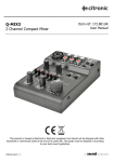
NPC30A
Noise Pollution Control System
Item ref: 952.801UK
User Manual
Initial Power Up
On initial power up the timer/power indicator will flash
and the OK indicator LED will then illuminate. Due to
certain installation conditions the T1 and T2 indicator
LEDs may flash before returning to the OK indication
LED. This unit is now ready for adjustment.
Adjustment
VR-1 (the overall microphone gain) should be adjusted*
accordingly to determine the desired decibel (dB) level
required to trigger the unit.
Fine Adjustment
VR-2 high filter adjustment - this should be adjusted*
if you require more or less sensitivity to high
frequencies, eg. vocals, etc.
VR-3 low filter adjustment - this should be adjusted* if
you require more or less sensitivity to low frequencies,
eg. bass.
*Adjustment:
Anti clockwise = less sensitive, Clockwise = more sensitive
VR-5 timer adjustment - this is normally set to 1 - 1.5
second intervals giving an overall time of approximately
7 - 10 x 2 seconds. Interval steps can be set by
observing the flashing power indicator LED once on plus
once off = 1 clock pulse. 5 pulses = cut off, 5 more
pulses to auto reset. 10 pulses = 1 complete cycle.
After being triggered and the volume not being reduced,
the unit will then cut off for the time you have pre-set
and then it will reset.
Keyswitch
Monitor - allows the unit to assess the music but it will
not cut off the power if the preset level is met.
Active - allows the unit to monitor the music but will cut
off the power if the preset level is met.
MAIN PANEL CONNECTIONS
M1
= Microphone +
M2
= Microphone – (earth/screen)
Ensure screened microphone cable is used to connect
mic to M1 and M2.
Note: On board relay connections (J and K) can be
regarded as an On/Off switch (i.e. when unit displays
green ON LED, contacts are closed, when red OFF LED
is displayed contacts are open circuit). The unit must be
powered up and the mic must be connected to ensure
steady Green OK LED, otherwise J-K is open circuit.
J
K
J-K
= on board relay normally open
(when unit is not powered up)
= on board relay common
= used to switch the 30 amp relay coil/contactor
coil or other device depending on installation
requirements
Note: Connections A-D are low voltage drive outputs
only, and are connected to corresponding connections
on remote light display if fitted.
A
B
C
D
FA1
FA3
P1
= traffic lights 0 volt (common)
= traffic lights red channel
= traffic lights yellow channel
= traffic lights green channel
= fire alarm +24Vdc input from any existing
fire alarm system (usually nearest bell or siren)
= fire alarm negative input
= earth
P2/P2A and P3/P3A are 18Vac input/output
connections from TX1 secondary mains transformer.
The 18Vac available at these connectors is also used
to power low voltage auxiliary panels or devices,
eg. remote relays, etc.
RELAY PANEL CONNECTIONS
J connects to J on main board (already connected)
K connects to K on main board (already connected)
P2 connects to P2 on main board (already connected)
P3 connects to P3 on main board (already connected)
2CN1 30 AMP CONNECTOR
L
= 24Vac supply input LIVE
N
= 240Vac supply input NEUTRAL
E
= input EARTH
Note: It is recommended that the supply to CN1 is taken from
a separate 30 amp ELCB/RCCD in the on site consumer unit.
2CN2 30 AMP OUTPUR CONNECTOR
L
= 240Vac controlled output LIVE
N
= 240Vac controlled output NEUTRAL
E
= output EARTH
2CN3: Live, neutral and earth connections to TX1 primary
(already connected).
TRAFFIC LIGHT REMOTE DISPLAY (952.804UK)
A, B, C, D connect to corresponding connectors on main panel
(240Vac mains powered displays should be supplied via 5 amp
switched spur or similar to Euro connector, low voltage
connections, A, B, C, D still connect to A, B, C, D respectively
on main panel).
Errors and omissions excepted.
Copyright© 2015. AVSL Group Ltd.
952.801UK User Manual