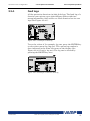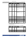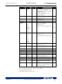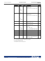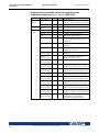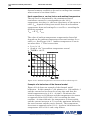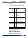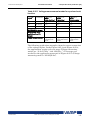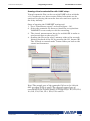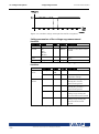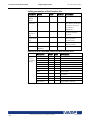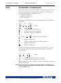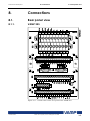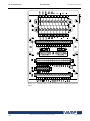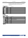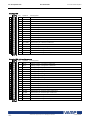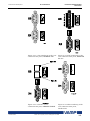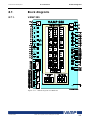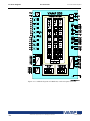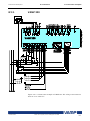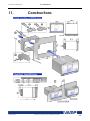
1
VAMP 255/245/230 Feeder and motor managers Operation and configuration instructions Technical description Table of Contents Operation and configuration Table of Contents 1. General ................................................................................... 3 1.1. Relay features .....................................................................3 1.2. User interface ......................................................................4 1.3. Operating Safety ................................................................4 2. Local panel user interface .................................................... 5 2.1. Relay front panel ................................................................5 2.1.1. Display .........................................................................6 2.1.2. Menu navigation and pointers ................................7 2.1.3. Keypad ........................................................................7 2.1.4. Operation Indicators .................................................8 2.1.5. Adjusting display contrast ........................................9 2.2. Local panel operations .....................................................9 2.2.1. Navigating in menus .................................................9 2.2.2. Menu structure of protection functions .............. 14 2.2.3. Setting groups ......................................................... 18 2.2.4. Fault logs .................................................................. 19 2.2.5. Operating levels...................................................... 20 2.3. Operating measures ....................................................... 22 2.3.1. Control functions .................................................... 22 2.3.2. Measured data ....................................................... 23 2.3.3. Reading event register .......................................... 26 2.3.4. Forced control (Force) ........................................... 27 2.4. Configuration and parameter setting ......................... 28 2.4.1. Parameter setting ................................................... 29 2.4.2. Setting range limits ................................................. 30 2.4.3. Disturbance recorder menu DR ........................... 30 2.4.4. Configuring digital inputs DI .................................. 31 2.4.5. Configuring digital outputs DO ............................ 31 2.4.6. Protection menu Prot ............................................. 32 2.4.7. Configuration menu CONF ................................... 32 2.4.8. Protocol menu Bus .................................................. 34 2.4.9. Single line diagram editing ................................... 37 2.4.10. Blocking and interlocking configuration ............. 37 3. VAMPSET PC software .......................................................... 38 2 VAMP 24h support phone +358 (0)20 753 3264 VM255.EN023 Operation and configuration 1. 1 General 1.1 Relay features General This first part (Operation and configuration) of the publication contains general descriptions of the functions, of the generator protection relay as well as operation instructions. It also includes instructions for parameterization and configuration of the relay and instructions for changing settings. The second part (Technical description) of the publication includes detailed protection function descriptions as well as application examples and technical data sheets. The Mounting and Commissioning Instructions are published in a separate publication with the code VMMC.EN0xx. 1.1. Relay features Function name VAMP 255 IEC symbol VAMP 245 IEEE/ ANSI code VAMP 230 The comprehensive protection functions of the relay make it ideal for utility, industrial, marine and off-shore power distribution applications. The relay features the following protection functions. List of protection functions X X X Protection functions 50/51 67 46 Overcurrent protection Idir>, Idir>>, Idir>>>, Idir>>>> I2> Directional overcurrent protection I2> 46 Current unbalance protection in feeder mode Current unbalance protection in moor mode X X X X X X X X * I2>> Incorrect phase sequence protection X X X 48 Ist> Stall protection X X X * 66 N> Frequent start protection X X X * 37 I< Undercurrent protection X X X Directional earth fault protection X X X I0>, I0>>, I0>>>, I0>>>> Earth fault protection X X X I0T > X X X X X X 47 67N 50N/51N 59C Uc> Intermittent transient earth fault protection Capacitor bank unbalance protection Capacitor overvoltage protection 59N U0>, U0>> Residual voltage protection X X X 49 T> Thermal overload protection X X X 59 U>, U>>, U>>> Overvoltage protection X X 27 U<, U<<, U<<< Undervoltage protection X X 67NT VM255.EN023 3I>, 3I>>, 3I>>> VAMP 24h support phone +358 (0)20 753 3264 * X 3 32 81H/81L 81L 81R 25 VAMP 255 IEEE/ ANSI code Operation and configuration VAMP 245 1 General VAMP 230 1.2 User interface IEC symbol Function name P<, P<< Reverse and underpower protection X X f><, f>><< Overfrequency and underfrequency protection X X f<, f<< Underfrequency protection X X df/dt Rate of change of frequency (ROCOF) protection X X ∆f, ∆U, ∆φ Synchrocheck X 51F2 If2> Second harmonic O/C stage X X X 50BF CBFP Circuit-breaker failure protection X X X Prg1…8 Programmable stages X X X ArcI>, ArcI01>, ArcI02> Optional arc fault protection X X X 99 50ARC/ 50NARC X *) Only available when application mode is motor protection Further the relay includes a disturbance recorder. Arc protection is optionally available. The relay communicates with other systems using common protocols, such as the Modbus RTU, ModbusTCP, Profibus DP, IEC 60870-5-103, IEC 60870-5-101, IEC 61850, SPA bus, Ethernet / IP, DNP TCP, DNP 3.0 and Device Net. 1.2. User interface The relay can be controlled in three ways: Locally with the push-buttons on the relay front panel Locally using a PC connected to the serial port on the front panel or on the rear panel of the relay (both cannot be used simultaneously) Via remote control over the remote control port on the relay rear panel. 1.3. Operating Safety The terminals on the rear panel of the relay may carry dangerous voltages, even if the auxiliary voltage is switched off. A live current transformer secondary circuit must not be opened. Disconnecting a live circuit may cause dangerous voltages! Any operational measures must be carried out according to national and local handling directives and instructions. Carefully read through all operation instructions before any operational measures are carried out. 4 VAMP 24h support phone +358 (0)20 753 3264 VM255.EN023 Operation and configuration 2 Local panel user interface 2.1 Relay front panel 2. Local panel user interface 2.1. Relay front panel VS_Display The figure below shows, as an example, the front panel of the feeder and motor manager VAMP 255 and the location of the user interface elements used for local control. Figure 2.1-1. The front panel of VAMP 255 1. 2. 3. 4. VM255.EN023 LCD dot matrix display Keypad LED indicators RS 232 serial communication port for PC VAMP 24h support phone +358 (0)20 753 3264 5 2.1 Relay front panel 2.1.1. 2 Local panel user interface Operation and configuration Display The relay is provided with a backlightedt 128x64 LCD dot matrix display. The display enables showing 21 characters in one row and eight rows at the same time. The display has two different purposes: one is to show the single line diagram of the relay with the object status, measurement values, identification etc. (Figure 2.1.1-1). The other purpose is to show the configuration and parameterization values of the relay (Figure 2.1.1-2). Figure 2.1.1-1 Sections of the LCD dot matrix display 1. 2. 3. 4. 5. 6. 7. Freely configurable single-line diagram Five controllable objects Six object statuses Bay identification Local/Remote selection Auto-reclose on/off selection (if applicable) Freely selectable measurement values (max. six values) Figure 2.1.1-2 Sections of the LCD dot matrix display 1. 2. 3. 4. 5. 6. Main menu column The heading of the active menu The cursor of the main menu Possible navigating directions (push buttons) Measured/setting parameter Measured/set value DIAPP_BackLight.txt 6 VAMP 24h support phone +358 (0)20 753 3264 VM255.EN023 Operation and configuration 2 Local panel user interface 2.1 Relay front panel Backlight control Display backlight can be switched on with a digital input, virtual input or virtual output. LOCALPANEL CONF/Display backlight ctrl setting is used for selecting trigger input for backlight control. When the selected input activates (rising edge), display backlight is set on for 60 minutes. 2.1.2. Menu navigation and pointers 1. Use the arrow keys UP and DOWN to move up and down in the main menu, that is, on the left-hand side of the display. The active main menu option is indicated with a cursor. The options in the main menu items are abbreviations, e.g. Evnt = events. 2. After any selection, the arrow symbols in the upper left corner of the display show the possible navigating directions (applicable navigation keys) in the menu. 3. The name of the active submenu and a possible ANSI code of the selected function are shown in the upper part of the display, e.g. CURRENTS. 4. Further, each display holds the measured values and units of one or more quantities or parameters, e.g. ILmax 300A. 2.1.3. Keypad You can navigate in the menu and set the required parameter values using the keypad and the guidance given in the display. Furthermore, the keypad is used to control objects and switches on the single line diagram display. The keypad is composed of four arrow keys, one cancel key, one enter key and one info key. Figure 2.1.3-1 Keys on the keypad 1. 2. 3. 4. Enter and confirmation key (ENTER) Cancel key (CANCEL) Up/Down [Increase/Decrease] arrow keys (UP/DOWN) Keys for selecting submenus [selecting a digit in a numerical value] (LEFT/RIGHT) 5. Additional information key (INFO) NOTE! The term, which is used for the buttons in this manual, is inside the brackets. VM255.EN023 VAMP 24h support phone +358 (0)20 753 3264 7 2.1 Relay front panel 2.1.4. 2 Local panel user interface Operation and configuration Operation Indicators The relay is provided with eight LED indicators: Figure 2.1.4-1. Operation indicators of the relay LED indicator Power LED lit Error LED lit Com LED lit or flashing Alarm LED lit Trip LED lit A- C LED lit 8 Meaning The auxiliary power has been switched on Internal fault, operates in parallel with the self supervision output relay The serial bus is in use and transferring information One or several signals of the output relay matrix have been assigned to output LA and the output has been activated by one of the signals. (For more information about output matrix, please see chapter 2.4.5). One or several signals of the output relay matrix have been assigned to output Tr, and the output has been activated by one of the signals. (For more information about output relay configuration, please see chapter 2.4.5). Application-related status indicators. VAMP 24h support phone +358 (0)20 753 3264 Measure/ Remarks Normal operation state The relay attempts to reboot [REBOOT]. If the error LED remains lit, call for maintenance. Normal operation state The LED is switched off when the signal that caused output Al to activate, e.g. the START signal, is reset. The resetting depends on the type of configuration, connected or latched. The LED is switched off when the signal that caused output Tr to activate, e.g. the TRIP signal, is reset. The resetting depends on the type of configuration, connected or latched. Configurable VM255.EN023 Operation and configuration 2 Local panel user interface 2.2 Local panel operations Resetting latched indicators and output relays All the indicators and output relays can be given a latching function in the configuration. There are several ways to reset latched indicators and relays: From the alarm list, move back to the initial display by pushing the CANCEL key for approx. 3 s. Then reset the latched indicators and output relays by pushing the ENTER key. Acknowledge each event in the alarm list one by one by pushing the ENTER key equivalent times. Then, in the initial display, reset the latched indicators and output relays by pushing the ENTER key. The latched indicators and relays can also be reset via a remote communication bus or via a digital input configured for that purpose. 2.1.5. Adjusting display contrast LCD_Contrast The readability of the LCD varies with the brightness and the temperature of the environment. The contrast of the display can be adjusted via the PC user interface, see chapter 3. 2.2. Local panel operations The front panel can be used to control objects, change the local/ remote status, read the measured values, set parameters, and to configure relay functions. Some parameters, however, can only be set by means of a PC connected to one of the local communication ports. Some parameters are factory-set. 2.2.1. Navigating in menus All the menu functions are based on the main menu/submenu structure: 1. Use the arrow keys UP and DOWN to move up and down in the main menu. 2. To move to a submenu, repeatedly push the RIGHT key until the required submenu is shown. Correspondingly, push the LEFT key to return to the main menu. 3. Push the ENTER key to confirm the selected submenu. If there are more than six items in the selected submenu, a black line appears to the right side of the display (Figure 2.2.1-1). It is then possible to scroll down in the submenu. VM255.EN023 VAMP 24h support phone +358 (0)20 753 3264 9 2.2 Local panel operations 2 Local panel user interface Operation and configuration Figure 2.2.1-1. Example of scroll indication 4. Push the CANCEL key to cancel a selection. 5. Pushing the UP or DOWN key in any position of a submenu, when it is not selected, brings you directly one step up or down in the main menu. The active main menu selection is indicated with black background color. The possible navigating directions in the menu are shown in the upper-left corner by means of black triangular symbols. 10 VAMP 24h support phone +358 (0)20 753 3264 VM255.EN023 Operation and configuration 2 Local panel user interface 2.2 Local panel operations Figure 2.2.1-2. Principles of the menu structure and navigation in the menus 6. Push the INFO key to obtain additional information about any menu item. 7. Push the CANCEL key to revert to the normal display. VM255.EN023 VAMP 24h support phone +358 (0)20 753 3264 11 2.2 Local panel operations 2 Local panel user interface Operation and configuration Main menu The general menu structure is shown in Figure 2.2.1-2. The menu is dependent on the user's configuration and the options according the order code. For example only the enabled protection stages will appear in the menu. A list of the local main menu Main menu Number of menus 1 5 1 12 P E I U Dema Umax 14 4 13 15 15 5 Imax 9 Pmax 5 Mont 21 Evnt DR Runh 2 2 2 TIMR DI 6 5 DO 4 ExtAI ExDI ExDO Prot 3 3 3 27 I> I>> 5 3 Description Interactive mimic display Double size measurements defined by the user Title screen with device name, time and firmware version. Power measurements Energy measurements Current measurements Voltage measurements Demand values Time stamped min & max of voltages Time stamped min & max of currents Time stamped min & max of power and frequency Maximum values of the last 31 days and the last twelve months Events Disturbance recorder Running hour counter. Active time of a selected digital input and time stamps of the latest start and stop. Day and week timers Digital inputs including virtual inputs Digital outputs (relays) and output matrix External analogue inputs External digital inputs External digital outputs Protection counters, combined overcurrent status, protection status, protection enabling, cold load and inrush detectionIf2> and block matrix 1st overcurrent stage 2nd overcurrent stage VAMP 24h support phone +358 (0)20 753 3264 ANSI code Note 1 1 2 3 3 3 50/51 50/51 4 4 VM255.EN023 Operation and configuration 2 Local panel user interface Main menu VM255.EN023 I>>> I> Number of menus 3 6 I>> 6 I>>> 4 I>>>> 4 I< I2> T> Uc> Io> Io>> Io>>> Io>>>> Io> Io>> Ioint> U> U>> U>>> U< U<< U<<< Uo> Uo>> P< 3 3 3 4 5 3 3 3 6 6 4 4 3 3 4 3 3 3 3 3 P<< 3 f>< f>><< f< f<< dfdt 4 4 4 4 3 Prg1 Prg2 Prg3 Prg4 Prg5 Prg6 Prg7 Prg8 3 3 3 3 3 3 3 3 2.2 Local panel operations Description ANSI code Note 3rd overcurrent stage 1st directional overcurrent stage 2nd directional overcurrent stage 3rd directional overcurrent stage 4th directional overcurrent stage Undercurrent stage Current unbalance stage Thermal overload stage Capacitor O/V stage 1st earth fault stage 2nd earth fault stage 3rd earth fault stage 4th earth fault stage 1st directional earth fault stage 2nd directional earth fault stage Transient intermittent E/F 1st overvoltage stage 2nd overvoltage stage 3rd overvoltage stage 1st undervoltage stage 2nd undervoltage stage 3rd undervoltage stage 1st residual overvoltage stage 2nd residual overvoltage stage 1st reverse and underpower stage 2nd reverse and underpower stage 1st over/under-frequency stage 2nd over/under-frequency stage 1st underfrequency stage 2nd underfrequency stage Rate of change of frequency (ROCOF) stage 1st programmable stage 2nd programmable stage 3rd programmable stage 4th programmable stage 5th programmable stage 6th programmable stage 7th programmable stage 8th programmable stage 50/51 67 4 4 67 4 67 4 67 4 37 46 49 59C 50N/51N 50N/51N 50N/51N 50N/51N 67N 67N 67NI 59 59 59 27 27 27 59N 59N 32 4 4 4 4 4 4 4 4 4 4 4 4 4 4 4 4 4 4 4 4 32 4 81 81 81L 81L 81R 4 4 4 4 4 VAMP 24h support phone +358 (0)20 753 3264 4 4 4 4 4 4 4 4 13 2.2 Local panel operations 2 Local panel user interface Main menu If2> CBFP Number of menus 3 3 CBWE 4 AR CTSV VTSV ArcI> 15 1 1 4 ArcIo> 3 ArcIo2> 3 OBJ Lgic 11 2 CONF Bus 10+2 13 Diag 6 Operation and configuration Description Second harmonic O/C stage Circuit breaker failure protection Circuit breaker wearing supervision Auto-reclose CT supervisor VT supervisor Optional arc protection stage for phase-to-phase faults and delayed light signal. Optional arc protection stage for earth faults. Current input = I01 Optional arc protection stage for earth faults. Current input = I02 Object definitions Status and counters of user's logic Device setup, scaling etc. Serial port and protocol configuration Device selfdiagnosis ANSI code Note 51F2 50BF 4 4 4 79 50ARC 4 4 4 50NARC 4 50NARC 4 5 1 6 7 Notes 1 Configuration is done with VAMPSET 2 Recording files are read with VAMPSET 3 The menu is visible only if protocol "ExternalIO" is selected for one of the serial ports. Serial ports are configured in menu "Bus". 4 The menu is visible only if the stage is enabled. 5 Objects are circuit breakers, disconnectors etc.. Their position or status can be displayed and controlled in the interactive mimic display. 6 There are two extra menus, which are visible only if the access level "operator" or "configurator" has been opened with the corresponding password. 7 Detailed protocol configuration is done with VAMPSET. 2.2.2. Menu structure of protection functions The general structure of all protection function menus is similar although the details do differ from stage to stage. As an example the details of the second overcurrent stage I>> menus are shown below. 14 VAMP 24h support phone +358 (0)20 753 3264 VM255.EN023 Operation and configuration 2 Local panel user interface 2.2 Local panel operations First menu of I>> 50/51 stage Figure 2.2.2-1 First menu of I>> 50/51 stage This is the status, start and trip counter and setting group menu. The content is: Stat2 ClearSTCntrs TC SC SGrpDI Status – The stage is not detecting any fault at the moment. The stage can also be forced to pick-up or trip if the operating level is "Configurator" and the force flag below is on. Operating levels are explained in chapter 2.2.5. SCntr 5 The stage has picked-up a fault five times since the last reset of restart. This value can be cleared if the operating level is at least "Operator". TCntr 1 The stage has tripped two times since the last reset of restart. This value can be cleared if the operating level is at least "Operator". SetGrp 1 The active setting group is one. This value can be edited if the operating level is at least "Operator". Setting groups are explained in chapter 2.2.3. SGrpDI The setting group is not controlled by any digital input. This value can be edited if the operating level is at least "Configurator". Force Off The status forcing and output relay forcing is disabled. This force flag status can be set to "On" or back to "Off" if the operating level is at least "Configurator". If no front panel button is pressed within five minutes and there is no VAMPSET communication, the force flag will be set to "Off" position. The forcing is explained in chapter 2.3.4. VM255.EN023 VAMP 24h support phone +358 (0)20 753 3264 15 2.2 Local panel operations 2 Local panel user interface Operation and configuration Second menu of I>> 50/51 stage Figure 2.2.2-2. Second menu (next on the right) of I>> 50/51 stage This is the main setting menu. The content is: Stage setting group 1 These are the group 1 setting values. The other setting group can be seen by pressing push buttons ENTER and then RIGHT or LEFT. Setting groups are explained in chapter 2.2.3. 16 ILmax 403A The maximum of the three measured phase currents is at the moment 403 A. This is the value the stage is supervising. Status – Status of the stage. This is just a copy of the status value in the first menu. I>> 1013 A The pick-up limit is 1013 A in primary value. I>> 2.50xIn The pick-up limit is 2.50 times the rated current of the generator. This value can be edited if the operating level is at least "Operator". Operating levels are explained in chapter 2.2.5. t>> 0.60s The total operation delay is set to 600 ms. This value can be edited if the operating level is at least "Operator". VAMP 24h support phone +358 (0)20 753 3264 VM255.EN023 Operation and configuration 2 Local panel user interface 2.2 Local panel operations Third menu of I>> 50/51 stage Figure 2.2.2-3. Third and last menu (next on the right) of I>> 50/51 stage This is the menu for registered values by the I>> stage. Fault logs are explained in chapter 2.2.4. FAULT LOG 1 This is the latest of the eight available logs. You may move between the logs by pressing push buttons ENTER and then RIGHT or LEFT. 2006-09-14 Date of the log. 12:25:10.288 Time of the log. Type 1-2 The overcurrent fault has been detected in phases L1 and L2 (A & B, red & yellow, R&S, u&v). Flt 2.86xIn The fault current has been 2.86 per unit. Load 0.99xIn The average load current before the fault has been 0.99 pu. EDly 81% The elapsed operation delay has been 81% of the setting 0.60 s = 0.49 s. Any registered elapsed delay less than 100 % means that the stage has not tripped, because the fault duration has been shorter than the delay setting. SetGrp 1 The setting group has been 1. This line can be reached by pressing ENTER and several times the DOWN button. VM255.EN023 VAMP 24h support phone +358 (0)20 753 3264 17 2.2 Local panel operations 2 Local panel user interface Operation and configuration 2.2.3. Setting groups SGrpAct Most of the protection functions of the relay have two setting groups. These groups are useful for example when the network topology is changed frequently. The active group can be changed by a digital input, through remote communication or locally by using the local panel. The active setting group of each protection function can be selected separately. Figure 2.2.3-1 shows an example where the changing of the I> setting group is handled with digital input one (SGrpDI). If the digital input is TRUE, the active setting group is group two and correspondingly, the active group is group one, if the digital input is FALSE. If no digital input is selected (SGrpDI = -), the active group can be selected by changing the value of the parameter SetGrp. Figure 2.2.3-1. Example of protection submenu with setting group parameters The changing of the setting parameters can be done easily. When the desired submenu has been found (with the arrow keys), press the ENTER key to select the submenu. Now the selected setting group is indicated in the down-left corner of the display (See Figure 2.2.3-2). Set1 is setting group one and Set2 is setting group two. When the needed changes, to the selected setting group, have been done, press the LEFT or the RIGHT key to select another group (the LEFT key is used when the active setting group is 2 and the RIGHT key is used when the active setting group is 1). Figure 2.2.3-2. Example of I> setting submenu 18 VAMP 24h support phone +358 (0)20 753 3264 VM255.EN023 Operation and configuration 2.2.4. 2 Local panel user interface 2.2 Local panel operations Fault logs All the protection functions include fault logs. The fault log of a function can register up to eight different faults with time stamp information, fault values etc. Each function has its own logs (See Figure 2.2.4-1). Figure 2.2.4-1. Example of fault log To see the values of, for example, log two, press the ENTER key to select the current log (log one). The current log number is then indicated in the down-left corner of the display (See Figure 2.2.4-2, Log2 = log two). The log two is selected by pressing the RIGHT key once. Figure 2.2.4-2. Example of selected fault log VM255.EN023 VAMP 24h support phone +358 (0)20 753 3264 19 2.2 Local panel operations 2.2.5. PanelAccessLevel PCAccessLevel 2 Local panel user interface Operation and configuration Operating levels The device has three operating levels: User level, Operator level and Configurator level. The purpose of the access levels is to prevent accidental change of relay configurations, parameters or settings. USER level Use: Opening: Closing: Possible to read e.g. parameter values, measurements and events Level permanently open Closing not possible OPERATOR level Use: Possible to control objects and to change e.g. the settings of the protection stages Opening: Default password is 1 Setting state: Push ENTER Closing: The level is automatically closed after 10 minutes idle time. Giving the password 9999 can also close the level. CONFIGURATOR level Use: The configurator level is needed during the commissioning of the relay. E.g. the scaling of the voltage and current transformers can be set. Opening: Default password is 2 Setting state: Push ENTER Closing: The level is automatically closed after 10 minutes idle time. Giving the password 9999 can also close the level. 20 VAMP 24h support phone +358 (0)20 753 3264 VM255.EN023 Operation and configuration Change_pwd 2 Local panel user interface 2.2 Local panel operations Opening access 1. Push the INFO key and the ENTER key on the front panel. Figure 2.2.5-1. Opening the access level 2. Enter the password needed for the desired level: the password can contain four digits. The digits are supplied one by one by first moving to the position of the digit using the RIGHT key and then setting the desired digit value using the UP key. 3. Push the ENTER key. Password handling The passwords can only be changed using VAMPSET software connected to the local RS-232 port on the relay. It is possible to restore the password(s) in case the password is lost or forgotten. In order to restore the password(s), a relay program is needed. The serial port settings are 38400 bps, 8 data bits, no parity and one stop bit. The bit rate is configurable via the front panel. Command get pwd_break get serno Description Get the break code (Example: 6569403) Get the serial number of the relay (Example: 12345) Send both the numbers to [email protected] and ask for a password break. A device specific break code is sent back to you. That code will be valid for the next two weeks. Command set pwd_break=4435876 Description Restore the factory default passwords (“4435876” is just an example. The actual code should be asked from VAMP Ltd.) Now the passwords are restored to the default values (See chapter 2.2.5). VM255.EN023 VAMP 24h support phone +358 (0)20 753 3264 21 2.3 Operating measures 2 Local panel user interface 2.3. Operating measures 2.3.1. Control functions Operation and configuration The default display of the local panel is a single-line diagram including relay identification, Local/Remote indication, Autoreclose on/off selection and selected analogue measurement values. Please note that the operator password must be active in order to be able to control the objects. Please refer to page 21 Opening access. Toggling Local/Remote control 1. Push the ENTER key. The previously activated object starts to blink. 2. Select the Local/Remote object (“L” or “R” squared) by using the arrow keys. 3. Push the ENTER key. The L/R dialog opens. Select “REMOTE” to enable remote control and disable local control. Select “LOCAL” to enable local control and disable remote control. 4. Confirm the setting by pushing the ENTER key. The Local/Remote state will change. Object control 1. Push the ENTER key. The previously activated object starts to blink. 2. Select the object to control by using the arrow keys. Please note that only controllable objects can be selected. 3. Push the ENTER key. A control dialog opens. 4. Select the “Open” or “Close” command by using the UP and DOWN arrow keys. 5. Confirm the operation by pushing the ENTER key. The state of the object changes. Toggling virtual inputs 1. Push the ENTER key. The previously activated object starts to blink. 2. Select the virtual input object (empty or black square) 3. The dialog opens 4. Select “VIon” to activate the virtual input or select “VIoff” to deactivate the virtual input 22 VAMP 24h support phone +358 (0)20 753 3264 VM255.EN023 Operation and configuration 2.3.2. 2 Local panel user interface 2.3 Operating measures Measured data The measured values can be read from the P*, E*, I and U* menus and their submenus. Furthermore, any measurement value in the following table can be displayed on the main view next to the single line diagram. Up to six measurements can be shown. VM255.EN023 Value P * Q * S * * P.F. * f *** Pda * Qda * Sda * Pfda * fda * PL1 * PL2 * PL3 * QL1 * QL2 * QL3 * SL1 * SL2 * SL3 * PF_L1 * PF_L2 * PF_L3 * cos * tan * cosL1 * cosL2 * cosL3 * Iseq * Menu/Submenu P/POWER P/POWER P/POWER P/POWER P/POWER P/POWER P/15 MIN POWER P/15 MIN POWER P/15 MIN POWER P/15 MIN POWER P/15 MIN POWER P/POWER/PHASE 1 P/POWER/PHASE 1 P/POWER/PHASE 1 P/POWER/PHASE 1 P/POWER/PHASE 1 P/POWER/PHASE 1 P/POWER/PHASE 2 P/POWER/PHASE 2 P/POWER/PHASE 2 P/POWER/PHASE 2 P/POWER/PHASE 2 P/POWER/PHASE 2 P/COS & TAN P/COS & TAN P/COS & TAN P/COS & TAN P/COS & TAN P/PHASE SEQUENCIES Useq * P/PHASE SEQUENCIES Io Io2 fAdop E+ Eq+ EEqE+.nn * * * * * * * * P/PHASE SEQUENCIES P/PHASE SEQUENCIES P/PHASE SEQUENCIES E/ENERGY E/ENERGY E/ENERGY E/ENERGY E/DECIMAL COUNT VAMP 24h support phone +358 (0)20 753 3264 Description Active power [kW] Reactive power [kvar] Apparent power [kVA] Active power angle [] Power factor [ ] Frequency [Hz] Active power [kW] **** Reactive power [kvar] **** Apparent power [kVA] **** Power factor [ ] **** Frequency [Hz] **** Active power of phase 1 [kW] Active power of phase 2 [kW] Active power of phase 3 [kW] Reactive power of phase 1 [kvar] Reactive power of phase 2 [kvar] Reactive power of phase 3 [kvar] Apparent power of phase 1 [kVA] Apparent power of phase 2 [kVA] Apparent power of phase 3 [kVA] Power factor of phase 1 [ ] Power factor of phase 2 [ ] Power factor of phase 3 [ ] Cosine phi [ ] Tangent phi [ ] Cosine phi of phase L1 [ ] Cosine phi of phase L2 [ ] Cosine phi of phase L3 [ ] Actual current phase sequency [OK; Reverse; ??] Actual voltage phase sequency [OK; Reverse; ??] Io/Uo angle [] Io2/Uo angle [] Adopted frequency [Hz] Exported energy [MWh] Exported reactive energy [Mvar] Imported energy [MWh] Imported reactive energy [Mvar] Decimals of exported energy [ ] 23 2.3 Operating measures 2 Local panel user interface Value Eq.nn * E-.nn * Ewrap * E+ * Eq+ * Menu/Submenu E/DECIMAL COUNT E/DECIMAL COUNT E/DECIMAL COUNT E/E-PULSE SIZES E/E-PULSE SIZES EEq- * * E/E-PULSE SIZES E/E-PULSE SIZES E+ * E/E-PULSE DURATION Eq+ * E/E-PULSE DURATION E- * E/E-PULSE DURATION Eq- * E/E-PULSE DURATION E+ Eq+ EEqIL1 IL2 IL3 IL1da IL2da IL3da Io * * * * ** ** ** ** ** ** ** Io2 ** IoC ** I1 ** I2 ** I2/I1 ** E/E-pulse TEST E/E-pulse TEST E/E-pulse TEST E/E-pulse TEST I/PHASE CURRENTS I/PHASE CURRENTS I/PHASE CURRENTS I/PHASE CURRENTS I/PHASE CURRENTS I/PHASE CURRENTS I/SYMMETRIC CURRENTS I/SYMMETRIC CURRENTS I/SYMMETRIC CURRENTS I/SYMMETRIC CURRENTS I/SYMMETRIC CURRENTS I/SYMMETRIC CURRENTS THDIL ** I/HARM. DISTORTION THDIL1 ** I/HARM. DISTORTION THDIL2 ** I/HARM. DISTORTION THDIL3 ** I/HARM. DISTORTION Diagram ** 24 I/HARMONICS of IL1 VAMP 24h support phone +358 (0)20 753 3264 Operation and configuration Description Decimals of reactive energy [ ] Decimals of imported energy [ ] Energy control Pulse size of exported energy [kWh] Pulse size of exported reactive energy [kvar] Pulse size of imported energy [kWh] Pulse duration of imported reactive energy [ms] Pulse duration of exported energy [ms] Pulse duration of exported reactive energy [ms] Pulse duration of imported energy [ms] Pulse duration of imported reactive energy [ms] Test the exported energy pulse [ ] Test the exported reactive energy [ ] Test the imported energy [ ] Test the imported reactive energy [ ] Phase current IL1 [A] Phase current IL2 [A] Phase current IL3 [A] 15 min average for IL1 [A] 15 min average for IL2 [A] 15 min average for IL3 [A] Primary value of zerosequence/ residual current Io [A] Primary value of zerosequence/residual current Io2 [A] Calculated Io [A] Positive sequence current [A] Negative sequence current [A] Negative sequence current related to positive sequence current (for unbalance protection) [%] Total harmonic distortion of the mean value of phase currents [%] Total harmonic distortion of phase current IL1 [%] Total harmonic distortion of phase current IL2 [%] Total harmonic distortion of phase current IL3 [%] Harmonics of phase current IL1 [%] (See Figure 2.3.2-1) VM255.EN023 Operation and configuration 2 Local panel user interface Value Diagram ** Menu/Submenu I/HARMONICS of IL2 Diagram ** I/HARMONICS of IL3 Uline * U/LINE VOLTAGES U12 U23 U31 UL * * * * U/LINE VOLTAGES U/LINE VOLTAGES U/LINE VOLTAGES U(PHASE VOLTAGES UL1 UL2 UL3 Uo * * * *** U1 * U2 * U2/U1 * THDU * U/PHASE VOLTAGES U/PHASE VOLTAGES U/PHASE VOLTAGES U/SYMMETRIC VOLTAGES U/SYMMETRIC VOLTAGES U/SYMMETRIC VOLTAGES U/SYMMETRIC VOLTAGES U/HARM. DISTORTION THDUa * U/HARM. DISTORTION THDUb * U/HARM. DISTORTION THDUc * U/HARM. DISTORTION Diagram * U/HARMONICS of Ua Diagram * U/HARMONICS of Ub Diagram * U/HARMONICS of Uc Count Prev Total U/VOLT. INTERRUPTS U/VOLT. INTERRUPTS U/VOLT. INTERRUPTS * * * 2.3 Operating measures Description Harmonics of phase current IL2 [%] (See Figure 2.3.2-1) Harmonics of phase current IL3 [%] (See Figure 2.3.2-1) Average value for the three line voltages [V] Phase-to-phase voltage U12 [V] Phase-to-phase voltage U23 [V] Phase-to-phase voltage U31 [V] Average for the three phase voltages [V] Phase-to-earth voltage UL1 [V] Phase-to-earth voltage UL2 [V] Phase-to-earth voltage UL3 [V] Residual voltage Uo [%] Positive sequence voltage [%] Negative sequence voltage [%] Negative sequence voltage related to positive sequence voltage [%] Total harmonic distortion of the mean value of voltages [%] Total harmonic distortion of the voltage input a [%] Total harmonic distortion of the voltage input b [%] Total harmonic distortion of the voltage input c [%] Harmonics of voltage input Ua [%] (See Figure 2.3.2-1) Harmonics of voltage input Ub [%] (See Figure 2.3.2-1) Harmonics of voltage input Uc [%] (See Figure 2.3.2-1) Voltage interrupts counter [ ] Previous interruption [ ] Total duration of voltage interruptions [days, hours] Duration of previous interruption [s] Voltage status [LOW; NORMAL] Prev * U/VOLT. INTERRUPTS Status * U/VOLT. INTERRUPTS *) Only in VAMP255/230 **) In VAMP 245 this value is found under main menu „Meas‟ instead of „I‟ ***) In VAMP 245 this value is found at Meas/Miscellaneous ****) The depth of the window can be selected VM255.EN023 VAMP 24h support phone +358 (0)20 753 3264 25 2.3 Operating measures 2 Local panel user interface Operation and configuration Figure 2.3.2-1. Example of harmonics bar display 2.3.3. Reading event register VS_Events The event register can be read from the Evnt submenu: 1. Push the RIGHT key once. 2. The EVENT LIST appears. The display contains a list of all the events that have been configured to be included in the event register. Figure 2.3.3-1. Example of an event register 3. Scroll through the event list with the UP and DOWN keys. 4. Exit the event list by pushing the LEFT key. It is possible to set the order in which the events are sorted. If the “Order” -parameter is set to “New-Old”, then the first event in the EVENT LIST is the most recent event. 26 VAMP 24h support phone +358 (0)20 753 3264 VM255.EN023 Operation and configuration 2.3.4. 2 Local panel user interface 2.3 Operating measures Forced control (Force) In some menus it is possible to switch a signal on and off by using a force function. This feature can be used, for instance, for testing a certain function. The force function can be activated as follows: 1. Move to the setting state of the desired function, for example DO (see Chapter 2.4, on page 28). 2. Select the Force function (the background color of the force text is black). Figure 2.3.4-1. Selecting Force function 3. Push the ENTER key. 4. Push the UP or DOWN key to change the "OFF" text to "ON", that is, to activate the Force function. 5. Push the ENTER key to return to the selection list. Choose the signal to be controlled by force with the UP and DOWN keys, for instance the T1 signal. 6. Push the ENTER key to confirm the selection. Signal T1 can now be controlled by force. 7. Push the UP or DOWN key to change the selection from "0" (not alert) to "1" (alert) or vice versa. 8. Push the ENTER key to execute the forced control operation of the selected function, e.g., making the output relay of T1 to pick up. 9. Repeat the steps 7 and 8 to alternate between the on and off state of the function. 10. Repeat the steps 1...4 to exit the Force function. 11. Push the CANCEL key to return to the main menu. NOTE! All the interlockings and blockings are bypassed when the force control is used. VM255.EN023 VAMP 24h support phone +358 (0)20 753 3264 27 2.4 Configuration and parameter setting 2.4. 2 Local panel user interface Operation and configuration Configuration and parameter setting The minimum procedure to configure a relay is 1. Open the access level "Configurator". The default password for configurator access level is 2. 2. Set the rated values in menu [CONF] including at least current transformers, voltage transformers and generator ratings. Also the date and time settings are in this same main menu. 3. Enable the needed protection functions and disable the rest of the protection functions in main menu [Prot]. 4. Set the setting parameter of the enable protection stages according the application. 5. Connect the output relays to the start and trip signals of the enabled protection stages using the output matrix. This can be done in main menu [DO], although the VAMPSET program is recommended for output matrix editing. 6. Configure the needed digital inputs in main menu [DI]. 7. Configure blocking and interlockings for protection stages using the block matrix. This can be done in main menu [Prot], although VAMPSET is recommended for block matrix editing. VS_Mimic Some of the parameters can only be changed via the RS-232 serial port using the VAMPSET software. Such parameters, (for example passwords, blockings and mimic configuration) are normally set only during commissioning. Some of the parameters require the restarting of the relay. This restarting is done automatically when necessary. If a parameter change requires restarting, the display will show as Figure 2.4-1. Figure 2.4-1 Example of auto-reset display Press CANCEL to return to the setting view. If a parameter must be changed, press the ENTER key again. The parameter can now be set. When the parameter change is confirmed with the ENTER key, a [RESTART]- text appears to the top-right corner of the display. This means that auto-resetting is 28 VAMP 24h support phone +358 (0)20 753 3264 VM255.EN023 Operation and configuration 2 Local panel user interface 2.4 Configuration and parameter setting pending. If no key is pressed, the auto-reset will be executed within few seconds. 2.4.1. Parameter setting 1. Move to the setting state of the desired menu (for example CONF/CURRENT SCALING) by pushing the ENTER key. The Pick text appears in the upper-left part of the display. 2. Enter the password associated with the configuration level by pushing the INFO key and then using the arrow keys and the ENTER key (default value is 0002). For more information about the access levels, please refer to Chapter 2.2.5. 3. Scroll through the parameters using the UP and DOWN keys. A parameter can be set if the background color of the line is black. If the parameter cannot be set the parameter is framed. 4. Select the desired parameter (for example Inom) with the ENTER key. 5. Use the UP and DOWN keys to change a parameter value. If the value contains more than one digit, use the LEFT and RIGHT keys to shift from digit to digit, and the UP and DOWN keys to change the digits. 6. Push the ENTER key to accept a new value. If you want to leave the parameter value unchanged, exit the edit state by pushing the CANCEL key. Figure 2.4.1-1.Changing parameters VM255.EN023 VAMP 24h support phone +358 (0)20 753 3264 29 2.4 Configuration and parameter setting 2.4.2. 2 Local panel user interface Operation and configuration Setting range limits If the given parameter setting values are out-of-range values, a fault message will be shown when the setting is confirmed with the ENTER key. Adjust the setting to be within the allowed range. Figure 2.4.2-1 Example of a fault message The allowed setting range is shown in the display in the setting mode. To view the range, push the INFO key. Push the CANCEL key to return to the setting mode. Figure 2.4.2-2. Allowed setting ranges show in the display 2.4.3. Disturbance recorder menu DR Via the submenus of the disturbance recorder menu the following functions and features can be read and set: DISTURBANCE RECORDER Recording mode (Mode) Sample rate (Rate) Recording time (Time) Pre trig time (PreTrig) Manual trigger (MnlTrig) Count of ready records (ReadyRe) REC. COUPLING Add a link to the recorder (AddLink) Clear all links (ClrLnks) 30 VAMP 24h support phone +358 (0)20 753 3264 VM255.EN023 Operation and configuration 2 Local panel user interface 2.4 Configuration and parameter setting Available links: DO, DI Uline, Uphase IL U2/U1, U2, U1 I2/In, I2/I1, I2, I1, IoCalc CosFii PF, S, Q, P f Uo UL3, UL2, UL1 U31, U23, U12 Io2, Io IL3, IL2, IL1 Prms, Qrms, Srms Tanfii THDIL1, THDIL2, THDIL3 THDUa, THDUb, THDUc IL1RMS, IL2RMS, IL3RMS ILmin, ILmax, ULLmin, ULLmax, ULNmin, ULNmax fy, fz, U12y, U12z 2.4.4. Configuring digital inputs DI The following functions can be read and set via the submenus of the digital inputs menu: The status of digital inputs (DIGITAL INPUTS 1-6/18) Operation counters (DI COUNTERS) Operation delay (DELAYs for DigIn) The polarity of the input signal (INPUT POLARITY). Either normally open (NO) or normally closed (NC) circuit. Event enabling EVENT MASK1 2.4.5. Configuring digital outputs DO The following functions can be read and set via the submenus of the digital outputs menu: The status of the output relays (RELAY OUTPUTS1 and 2) The forcing of the output relays (RELAY OUTPUTS1 and 2) (only if Force = ON): o Forced control (0 or 1) of the Trip relays o Forced control (0 or 1) of the Alarm relays o Forced control (0 or 1) of the IF relay The configuration of the output signals to the output relays. The configuration of the operation indicators (LED) Alarm and Trip and application specific alarm leds A, B and C (that is, the output relay matrix). VM255.EN023 VAMP 24h support phone +358 (0)20 753 3264 31 2.4 Configuration and parameter setting 2 Local panel user interface Operation and configuration NOTE! The amount of Trip and Alarm relays depends on the relay type and optional hardware. 2.4.6. Protection menu Prot The following functions can be read and set via the submenus of the Prot menu: Reset all the counters (PROTECTION SET/ClAll) Read the status of all the protection functions (PROTECT STATUS 1-x) Enable and disable protection functions (ENABLED STAGES 1-x) Define the interlockings using block matrix (only with VAMPSET). Each stage of the protection functions can be disabled or enabled individually in the Prot menu. When a stage is enabled, it will be in operation immediately without a need to reset the relay. The relay includes several protection functions. However, the processor capacity limits the number of protection functions that can be active at the same time. 2.4.7. Configuration menu CONF The following functions and features can be read and set via the submenus of the configuration menu: DEVICE SETUP Bit rate for the command line interface in ports X4 and the front panel. The front panel is always using this setting. If SPABUS is selected for the rear panel local port X4, the bit rate is according SPABUS settings. Access level [Acc] VS_Scaling 32 LANGUAGE List of available languages in the relay CURRENT SCALING Rated phase CT primary current (Inom) Rated phase CT secondary current (Isec) Rated input of the relay [Iinput]. 5 A or 1 A. This is specified in the order code of the device. Rated value of I0 CT primary current (Ionom) Rated value of I0 CT secondary current (Iosec) Rated I01 input of the relay [Ioinp]. 5 A or 1 A. This is specified in the order code of the device. Rated value of I02 CT primary current (Io2nom) Rated value of I02 CT secondary current (Io2sec) Rated I02 input of the relay [Io2inp]. 5A, 1 A or 0.2 A. This is specified in the order code of the device. VAMP 24h support phone +358 (0)20 753 3264 VM255.EN023 Operation and configuration 2 Local panel user interface 2.4 Configuration and parameter setting The rated input values are usually equal to the rated secondary value of the CT. The rated CT secondary may be greater than the rated input but the continuous current must be less than four times the rated input. In compensated, high impedance earthed and isolated networks using cable transformer to measure residual current I0, it is quite usual to use a relay with 1 A or 0.2 A input although the CT is 5 A or 1A. This increases the measurement accuracy. The rated CT secondary may also be less than the rated input but the measurement accuracy near zero current will decrease. MOTOR CURRENT Rated current of the motor VOLTAGE SCALING Rated VT primary voltage (Uprim) Rated VT secondary voltage (Usec) Rated U0 VT secondary voltage (Uosec) Voltage measuring mode (Umode) DeviceName DeviceType SerNo Date Time UNITS FOR MIMIC DISPLAY Unit for voltages (V). The choices are V (volt) or kV (kilovolt). Scaling for active, reactive and apparent power [Power]. The choices are k for kW, kvar and kVA or M for MW, Mvar and MVA. DEVICE INFO Manager type (Type VAMP 2XX) Serial number (SerN) Software version (PrgVer) Bootcode version (BootVer) DATE/TIME SETUP Day, month and year (Date) Time of day (Time) Date format (Style). The choices are "yyyy-mm-dd", "dd.nn.yyyy" and "mm/dd/yyyy". CLOCK SYNCHRONISATION Digital input for minute sync pulse (SyncDI). If any digital input is not used for synchronization, select "". Daylight saving time for NTP synchronization (DST). Detected source of synchronization (SyScr). Synchronization message counter (MsgCnt). Latest synchronization deviation (Dev). VM255.EN023 VAMP 24h support phone +358 (0)20 753 3264 33 2.4 Configuration and parameter setting 2 Local panel user interface Operation and configuration The following parameters are visible only when the access level is higher than "User". Offset, i.e. constant error, of the synchronization source (SyOS). Auto adjust interval (AAIntv). Average drift direction (AvDrft): "Lead" or "lag". Average synchronization deviation (FilDev). 2.4.8. Protocol menu Bus VS_Protocol There are three communication ports in the rear panel. In addition there is a connector in the front panel overruling the local port in the rear panel. REMOTE PORT X5 Communication protocol for remote port X5 [Protocol]. Message counter [Msg#]. This can be used to verify that the device is receiving messages. Communication error counter [Errors]. Communication time-out error counter [Tout]. Information of bit rate/data bits/parity/stop bits. This value is not directly editable. Editing is done in the appropriate protocol setting menus. The counters are useful when testing the communication. LOCAL PORT X4 (pins 2, 3 and 5) This port is disabled, if a cable is connected to the front panel connector. Communication protocol for the local port X4 [Protocol]. For VAMPSET use "None" or "SPABUS". Message counter [Msg#]. This can be used to verify that the device is receiving messages. Communication error counter [Errors]. Communication time-out error counter [Tout]. Information of bit rate/data bits/parity/stop bits. This value is not directly editable. Editing is done in the appropriate protocol setting menus. For VAMPSET and protocol "None" the setting is done in menu CONF/DEVICE SETUP. PC (LOCAL/SPA BUS) This is a second menu for local port X4. The VAMPSET communication status is showed. Bytes/size of the transmitter buffer [Tx]. Message counter [Msg#]. This can be used to verify that the device is receiving messages. Communication error counter [Errors] Communication time-out error counter [Tout]. Same information as in the previous menu. 34 VAMP 24h support phone +358 (0)20 753 3264 VM255.EN023 Operation and configuration VS_ModBusMain VS_ModBusIO 2 Local panel user interface 2.4 Configuration and parameter setting EXTENSION PORT X4 (pins 7, 8 and 5) Communication protocol for extension port X4 [Protocol]. Message counter [Msg#]. This can be used to verify that the device is receiving messages. Communication error counter [Errors]. Communication time-out error counter [Tout]. Information of bit rate/data bits/parity/stop bits. This value is not directly editable. Editing is done in the appropriate protocol setting menus. Ethernet port These parameters are used by the ethernet interface. For changing the nnn.nnn.nnn.nnn style parameter values, VAMPSET is recommended. Ethernet port protocol [Protoc]. IP Port for protocol [Port] IP address [IpAddr]. Net mask [NetMsk]. Gateway [Gatew]. Name server [NameSw]. Network time protocol (NTP) server [NTPSvr]. TCP Keep alive interval [KeepAlive] MAC address [MAC] IP Port for Vampset [VS Port] Message counter [Msg#] Error counter [Errors] Timeout counter [Tout] MODBUS Modbus addres for this slave device [Addr]. This address has to be unique within the system. Modbus bit rate [bit/s]. Default is "9600". Parity [Parity]. Default is "Even". For details see the technical description part of the manual. EXTERNAL I/O protocol This is a Modbus master protocol to communicate with the extension I/O modules connected to the extension port. Only one instance of this protocol is possible. Bit rate [bit/s]. Default is "9600". Parity [Parity]. Default is "Even". For details see the technical description part of the manual. VS_SpaBusMain VM255.EN023 VAMP 24h support phone +358 (0)20 753 3264 35 2.4 Configuration and parameter setting VS_IEC103Main VS_ProfiBusMain 2 Local panel user interface Operation and configuration SPA BUS Several instances of this protocol are possible. SPABUS addres for this device [Addr]. This address has to be unique within the system. Bit rate [bit/s]. Default is "9600". Event numbering style [Emode]. Default is "Channel". For details see the technical description part of the manual. IEC 60870-5-103 Only one instance of this protocol is possible. Address for this device [Addr]. This address has to be unique within the system. Bit rate [bit/s]. Default is "9600". Minimum measurement response interval [MeasInt]. ASDU6 response time mode [SyncRe]. For details see the technical description part of the manual. IEC 103 DISTURBANCE RECORDINGS For details see the technical description part of the manual. PROFIBUS Only one instance of this protocol is possible. [Mode] Bit rate [bit/s]. Use 2400 bps. This parameter is the bit rate between the main CPU and the Profibus ASIC. The actual Profibus bit rate is automatically set by the Profibus master and can be up to 12 Mbit/s. Event numbering style [Emode]. Size of the Profibus Tx buffer [InBuf]. Size of the Profibus Rx buffer [OutBuf]. When configuring the Profibus master system, the length of these buffers are needed. The size of the both buffers is set indirectly when configuring the data items for Profibus. Address for this slave device [Addr]. This address has to be unique within the system. Profibus converter type [Conv]. If the shown type is a dash “-“, either Profibus protocol has not been selected or the device has not restarted after protocol change or there is a communication problem between the main CPU and the Profibus ASIC. For details see the technical description part of the manual. VS_DNP3 36 VAMP 24h support phone +358 (0)20 753 3264 VM255.EN023 Operation and configuration VS_IEC101Main 2.4.9. 2 Local panel user interface 2.4 Configuration and parameter setting DNP3 Only one instance of this protocol is possible. Bit rate [bit/s]. Default is "9600". [Parity]. Addres for this device [SlvAddr]. This address has to be unique within the system. Master's addres [MstrAddr]. For further details see the technical description part of the manual. IEC 60870-5-101 Bit rate [bit/s]. Default is “9600”. [Parity]. Link layer address for this device [LLAddr]. ASDU address [ALAddr]. For further details see the technical description part of the manual. Single line diagram editing The single-line diagram is drawn with the VAMPSET software. For more information, please refer to the VAMPSET manual (VMV.EN0xx). Figure 2.4.9-1. Single line diagram. 2.4.10. Blocking and interlocking configuration The configuration of the blockings and interlockings is done with the VAMPSET software. Any start or trip signal can be used for blocking the operation of any protection stage. Furthermore, the interlocking between objects can be configured in the same blocking matrix of the VAMPSET software. For more information, please refer to the VAMPSET manual (VMV.EN0xx). VM255.EN023 VAMP 24h support phone +358 (0)20 753 3264 37 3 VAMPSET PC software 3. Operation and configuration VAMPSET PC software The PC user interface can be used for: On-site parameterization of the relay Loading relay software from a computer Reading measured values, registered values and events to a computer. Continuous monitoring of all values and events. Two RS 232 serial ports are available for connecting a local PC with VAMPSET to the relay; one on the front panel and one on the rear panel of the relay. These two serial ports are connected in parallel. However, if the connection cables are connected to both ports, only the port on the front panel will be active. To connect a PC to a serial port, use a connection cable of type VX 003-3. The VAMPSET program can also use TCP/IP LAN connection. Optional hardware is required. There is a free of charge PC program called VAMPSET available for configuration and setting of VAMP relays. Please download the latest VAMPSET.exe from our web page www.vamp.fi. For more information about the VAMPSET software, please refer to the user‟s manual with the code VMV.EN0xx. Also the VAMPSET user‟s manual is available at our web site. 38 VAMP 24h support phone +358 (0)20 753 3264 VM255.EN023 Technical description Table of Contents Table of Contents 1. Introduction .......................................................................... 43 1.1. Main features ................................................................... 44 1.2. Principles of numerical protection techniques .......... 45 2. Protection functions ............................................................. 47 2.1. Maximum number of protection stages in one application ................................................................................ 47 2.2. General features of protection stages ........................ 47 2.3. List of functions ................................................................ 51 2.4. Function dependencies ................................................. 53 2.4.1. Application modes ................................................. 53 2.4.2. Current protection function dependencies....... 53 2.5. Overcurrent stage I> (50/51) ......................................... 54 2.6. Directional overcurrent protection Idir> (67) ............... 58 2.7. Current unbalance stage I 2> (46) in feeder mode.... 63 2.8. Current unbalance stage I 2> (46) in motor mode ..... 65 2.9. Incorrect phase sequence protection I 2>> (47) ........ 67 2.10. Stall protection Ist> (48) ................................................... 68 2.10.1. Motor status ............................................................. 69 2.11. Frequent start protection N> (66) ................................. 71 2.12. Undercurrent protection I< (37) .................................... 73 2.13. Directional earth fault protection I 0φ> (67N) ............... 73 2.14. Earth fault protection I0> (50N/51N) ............................. 80 2.15. Intermittent transient earth fault protection I0T> (67NT) 85 2.16. Capacitor bank unbalance protection ...................... 91 2.17. Capacitor overvoltage protection Uc> (59C) ........... 95 2.18. Zero sequence voltage protection U0> (59N) .......... 100 2.19. Thermal overload protection T> (49) ......................... 103 2.20. Overvoltage protection U> (59) ................................. 106 2.21. Undervoltage protection U< (27) ............................... 109 2.22. Reverse power and underpower protection P< (32) 112 2.23. Overfrequency and underfrequency Protection f>, f< (81H/81L) ................................................................................. 114 2.24. Rate of change of frequency (ROCOF) protection df/dt (81R) ............................................................................... 116 2.25. Synchrocheck protection (25) .................................... 121 2.26. Second harmonic O/C stage I f2>(51F2) .................... 129 2.27. Circuit breaker failure protection CBFP (50BF) ......... 131 2.28. Programmable stages (99) .......................................... 132 2.29. Arc fault protection (50ARC/50NARC)- optional ..... 136 2.30. Inverse time operation ................................................. 140 2.30.1. Standard inverse delays IEC, IEEE, IEEE2, RI ...... 143 2.30.2. Free parametrisation using IEC, IEEE and IEEE2 equations ........................................................................... 153 VM255.EN024 VAMP 24h support phone +358 (0)20 753 3264 39 Table of Contents Technical description 2.30.3. Programmable inverse time curves ................... 154 3. Supporting functions .......................................................... 155 3.1. Event log ......................................................................... 155 3.2. Disturbance recorder ................................................... 157 3.3. Cold load pick-up and inrush current detection ..... 162 3.4. Voltage sags and swells ............................................... 165 3.5. Voltage interruptions .................................................... 167 3.6. Current transformer supervision .................................. 169 3.7. Voltage transformer supervision ................................. 170 3.8. Circuit breaker condition monitoring ......................... 171 3.9. Energy pulse outputs .................................................... 177 3.10. System clock and synchronization ............................. 180 3.11. Running hour counter ................................................... 184 3.12. Timers ............................................................................... 185 3.13. Combined overcurrent status ..................................... 187 3.14. Self supervision ............................................................... 189 3.14.1. Diagnostics ............................................................ 189 3.15. Short circuit fault location ............................................ 191 3.16. Earth-fault location ....................................................... 195 4. Measurement functions ..................................................... 197 4.1. Measurement accuracy .............................................. 197 4.2. RMS values ..................................................................... 199 4.3. Harmonics and Total Harmonic Distortion (THD) ...... 200 4.4. Demand values ............................................................. 201 4.5. Minimum and maximum values.................................. 202 4.6. Maximum values of the last 31 days and twelve months ..................................................................................... 203 4.7. Voltage measurement mode ..................................... 204 4.8. Power calculation ......................................................... 205 4.9. Direction of power and current .................................. 207 4.10. Symmetric components ............................................... 208 4.11. Primary, secondary and per unit scaling................... 211 4.11.1. Current scaling ...................................................... 212 4.11.2. Voltage scaling ..................................................... 214 4.12. Analogue outputs (option) .......................................... 217 4.12.1. mA scaling examples ........................................... 217 5. Control functions ................................................................ 219 5.1. Output relays ................................................................. 219 5.2. Digital inputs ................................................................... 220 5.3. Virtual inputs and outputs ............................................ 222 5.4. Output matrix ................................................................. 222 5.5. Blocking matrix .............................................................. 223 5.6. Controllable objects ..................................................... 224 5.6.1. Local/Remote selection ...................................... 225 5.7. Auto-reclose function (79) ........................................... 226 5.8. Logic functions .............................................................. 233 6. Communication ................................................................. 234 40 VAMP 24h support phone +358 (0)20 753 3264 VM255.EN024 Technical description Table of Contents 6.1. Communication ports .................................................. 234 6.1.1. Local port X4 ......................................................... 235 6.1.2. Remote port X5 ..................................................... 237 6.1.3. Extension port X4 ................................................... 238 6.1.4. Ethernet port .......................................................... 239 6.2. Communication protocols .......................................... 240 6.2.1. PC communication .............................................. 240 6.2.2. Modbus TCP and Modbus RTU ........................... 240 6.2.3. Profibus DP ............................................................. 241 6.2.4. SPA-bus ................................................................... 243 6.2.5. IEC 60870-5-103 ..................................................... 243 6.2.6. DNP 3.0 ................................................................... 245 6.2.7. IEC 60870-5-101 ..................................................... 246 6.2.8. External I/O (Modbus RTU master) ..................... 247 6.2.9. IEC 61850 ................................................................ 247 6.2.10. EtherNet/IP ............................................................. 249 7. Applications........................................................................ 251 7.1. Substation feeder protection ...................................... 251 7.2. Industrial feeder protection ......................................... 252 7.3. Parallel line protection ................................................. 252 7.4. Ring network protection .............................................. 254 7.5. Trip circuit supervision ................................................... 254 7.5.1. Trip circuit supervision with one digital input .... 255 7.5.2. Trip circuit supervision with two digital inputs ... 263 8. Connections ....................................................................... 267 8.1. Rear panel view ............................................................ 267 8.1.1. VAMP 255 ............................................................... 267 8.1.2. VAMP 245 ............................................................... 273 8.1.3. VAMP 230 ............................................................... 278 8.2. Auxiliary voltage ............................................................ 283 8.3. Serial communication connectors ............................. 283 8.3.1. Front panel connector ......................................... 283 8.3.2. Rear panel connector X5 (REMOTE) .................. 284 8.3.3. X4 rear panel connector (local RS232 and extension RS485 ports) ..................................................... 288 8.4. Optional two channel arc protection card.............. 289 8.5. Optional digital I/O card (DI19/DI20)......................... 290 8.6. External I/O extension modules .................................. 291 8.6.1. External LED module VAM 16D ........................... 291 8.6.2. External input / output module .......................... 291 8.7. Block diagrams .............................................................. 297 8.7.1. VAMP 255 ............................................................... 297 8.7.2. VAMP 245 ............................................................... 299 8.7.3. VAMP 230 ............................................................... 301 8.8. Block diagrams of option modules ............................ 303 8.8.1. Optional arc protection ...................................... 303 8.8.2. Optional DI19/DI20 ............................................... 303 VM255.EN024 VAMP 24h support phone +358 (0)20 753 3264 41 Table of Contents Technical description 8.9. Connection examples .................................................. 304 8.9.1. VAMP 255 ............................................................... 304 8.9.2. VAMP 245 ............................................................... 308 8.9.3. VAMP 230 ............................................................... 309 9. Technical data ................................................................... 312 9.1. Connections................................................................... 312 9.1.1. Measuring circuitry ............................................... 312 9.1.2. Auxiliary voltage ................................................... 313 9.1.3. Digital inputs .......................................................... 313 9.1.4. Trip contacts .......................................................... 313 9.1.5. Alarm contacts ..................................................... 314 9.1.6. Local serial communication port ....................... 314 9.1.7. Remote control connection ............................... 314 9.1.8. Arc protection interface (option) ...................... 315 9.1.9. Analogue output connections (option) ........... 315 9.1.10. Arc protection interface (option) ...................... 315 9.2. Tests and environmental conditions .......................... 316 9.2.1. Disturbance tests .................................................. 316 9.2.2. Dielectric test voltages ........................................ 316 9.2.3. Mechanical tests .................................................. 316 9.2.4. Environmental conditions .................................... 316 9.2.5. Casing .................................................................... 316 9.2.6. Package................................................................. 317 9.3. Protection functions ...................................................... 317 9.3.1. Non-directional current protection ................... 317 9.3.2. Directional current protection ............................ 322 9.3.3. Frequent start protection .................................... 324 9.3.4. Voltage protection ............................................... 324 9.3.5. Frequency protection .......................................... 325 9.3.6. Power protection .................................................. 326 9.3.7. Synchrocheck function........................................ 327 9.3.8. Second harmonic function ................................. 327 9.3.9. Circuit-breaker failure protection ...................... 327 9.3.10. Arc fault protection (option) .............................. 328 9.4. Supporting functions ..................................................... 329 9.4.1. Inrush current detection (68) .............................. 329 9.4.2. Disturbance recorder (DR) .................................. 329 9.4.3. Transformer supervision ........................................ 329 9.4.4. Voltage sag & swell .............................................. 330 9.4.5. Voltage interruptions ............................................ 330 10. Abbreviations and symbols .............................................. 331 11. Constructions ...................................................................... 333 12. Order information ............................................................... 334 13. Revision history ................................................................... 338 14. Reference information ....................................................... 343 42 VAMP 24h support phone +358 (0)20 753 3264 VM255.EN024 Technical description 1. 1 Introduction 1.1 Main features Introduction This part of the user manual describes the protection functions, provides a few application examples and contains technical data. The numerical VAMP feeder and motor protection device includes all the essential protection functions needed to protect feeders and motors in distribution networks of utilities, industry, power plants and offshore applications. Further, the device includes several programmable functions, such as arc (option), thermal, trip circuit supervision and circuit breaker protection and communication protocols for various protection and communication situations. Figure 1.1-1. Application of the feeder and motor protection device VM255.EN024 VAMP 24h support phone +358 (0)20 753 3264 43 1.1 Main features 1.1. 1 Introduction Main features 44 Technical description Fully digital signal handling with a powerful 16-bit microprocessor, and high measuring accuracy on all the setting ranges due to an accurate 16-bit A/D conversion technique. Wide setting ranges for the protection functions, e.g. the earth fault protection can reach a sensitivity of 0.5%. Integrated fault location for short-circuit faults. The device can be matched to the requirements of the application by disabling the functions that are not needed. Flexible control and blocking possibilities due to digital signal control inputs (DI) and outputs (DO). Easy adaptability of the device to various substations and alarm systems due to flexible signal-grouping matrix in the device. Possibility to control six objects (e.g. circuit-breakers, disconnectors). Status of eight objects (e.g. circuit-breakers, disconnectors, switches). Freely configurable display with six measurement values. Freely configurable interlocking schemes with basic logic functions. Recording of events and fault values into an event register from which the data can be read via a keypad and a local HMI or by means of a PC based VAMPSET user interface. Latest events and indications are in non-volatile memory. Easy configuration, parameterisation and reading of information via local HMI, or with a VAMPSET user interface. Easy connection to power plant automation system due to a versatile serial connection and several available communication protocols. Built-in, self-regulating ac/dc converter for auxiliary power supply from any source within the range from 40 to 265 VDC or VAC. The alternative power supply is for 18 to 36 VDC. Built-in disturbance recorder for evaluating all the analogue and digital signals. VAMP 24h support phone +358 (0)20 753 3264 VM255.EN024 Technical description 1.2. 1 Introduction 1.2 Principles of numerical protection techniques Principles of numerical protection techniques The device is fully designed using numerical technology. This means that all the signal filtering, protection and control functions are implemented through digital processing. The numerical technique used in the device is primarily based on an adapted Fast Fourier Transformation (FFT). In FFT the number of calculations (multiplications and additions), which are required to filter out the measuring quantities, remains reasonable. By using synchronized sampling of the measured signal (voltage or current) and a sample rate according to the 2n series, the FFT technique leads to a solution, which can be realized with just a 16 bit micro controller, without using a separate DSP (Digital Signal Processor). The synchronized sampling means an even number of 2n samples per period (e.g. 32 samples per a period). This means that the frequency must be measured and the number of the samples per period must be controlled accordingly so that the number of the samples per period remains constant if the frequency changes. Therefore secondary testing of a brand new device should be started with voltage protection functions and voltage injection to let the relay learn the local frequency. However, if this is not possible then the frequency must be parameterised to the device. Apart from the FFT calculations, some protection functions also require the symmetrical components to be calculated for obtaining the positive, negative and zero phase sequence components of the measured quantity. For example, the function of the unbalanced load protection stage is based on the use of the negative phase sequence component of the current. Figure 1.2-1 shows a principle block diagram of a numerical device. The main components are the energizing inputs, digital input elements, output relays, A/D converters and the micro controller including memory circuits. Further, a device contains a power supply unit and a human-machine interface (HMI). Figure 1.2-2 shows the heart of the numerical technology. That is the main block diagram for calculated functions. Figure 1.2-3 shows a principle diagram of a single-phase overvoltage or overcurrent function. VM255.EN024 VAMP 24h support phone +358 (0)20 753 3264 45 1.2 Principles of numerical protection techniques 1 Introduction Technical description Figure 1.2-1 Principle block diagram of the VAMP hardware Figure 1.2-2 Block diagram of signal processing and protection software Figure 1.2-3 Block diagram of a basic protection function 46 VAMP 24h support phone +358 (0)20 753 3264 VM255.EN024 Technical description 2. 2 Protection functions 2.1 Maximum number of protection stages in one application Protection functions Each protection stage can independently be enabled or disabled according to the requirements of the intended application. 2.1. Maximum number of protection stages in one application ProtCnt The device limits the maximum number of enabled stages to about 30, depending of the type of the stages. For more information, please see the configuration instructions in chapter 2.4 in the Operation and Configuration instruction. 2.2. General features of protection stages SGrpAct Setting groups Most stages have two setting groups. Changing between setting groups can be controlled manually or using any of the digital inputs, virtual inputs, virtual outputs or LED indicator signals. By using virtual I/O the active setting group can be controlled using the local panel mimic display, any communication protocol or using the inbuilt programmable logic functions. Forcing start or trip condition for testing The status of a protection stage can be one of the followings: The stage is not detecting any fault. Ok = ′–′ Blocked The stage is detecting a fault but blocked by some reason. Start The stage is counting the operation delay. Trip The stage has tripped and the fault is still on. The blocking reason may be an active signal via the block matrix from other stages, the programmable logic or any digital input. Some stages also have inbuilt blocking logic. For example an under frequency stage is blocked if voltage is too low. For more details about block matrix, see chapter 5.5. VM255.EN024 VAMP 24h support phone +358 (0)20 753 3264 47 2.2 General features of protection stages 2 Protection functions Technical description Forcing start or trip condition for testing purposes There is a "Force flag" parameter which, when activated, allows forcing the status of any protection stage to be "start" or "trip" for a half second. By using this forcing feature any current or voltage injection to the device is not necessary to check the output matrix configuration, to check the wiring from the output relays to the circuit breaker and also to check that communication protocols are correctly transferring event information to a SCADA system. After testing the force flag will automatically reset 5-minute after the last local panel push button activity. The force flag also enables forcing of the output relays and forcing the optional mA outputs. Start and trip signals Every protection stage has two internal binary output signals: start and trip. The start signal is issued when a fault has been detected. The trip signal is issued after the configured operation delay unless the fault disappears before the end of the delay time. Output matrix Using the output matrix the user connects the internal start and trip signals to the output relays and indicators. For more details see chapter 5.4. Blocking Any protection function, except arc protection, can be blocked with internal and external signals using the block matrix (chapter 5.5). Internal signals are for example logic outputs and start and trip signals from other stages and external signals are for example digital and virtual inputs. Some protection stages have also inbuilt blocking functions. For example under-frequency protection has inbuilt under-voltage blocking to avoid tripping when the voltage is off. When a protection stage is blocked, it won't pick-up in case of a fault condition is detected. If blocking is activated during the operation delay, the delay counting is frozen until the blocking goes off or the pick-up reason, i.e. the fault condition, disappears. If the stage is already tripping, the blocking has no effect. Retardation time Retardation time is the time a protection relay needs to notice, that a fault has been cleared during the operation time delay. This parameter is important when grading the operation time delay settings between relays. 48 VAMP 24h support phone +358 (0)20 753 3264 VM255.EN024 Technical description 2 Protection functions 2.2 General features of protection stages Figure 2.2-1. Definition for retardation time. If the delay setting would be slightly shorter, an unselective trip might occur (the dash line pulse). For example when there is a big fault in an outgoing feeder, it might start i.e. pick-up both the incoming and outgoing feeder relay. However the fault must be cleared by the outgoing feeder relay and the incoming feeder relay must not trip. Although the operating delay setting of the incoming feeder is more than at the outgoing feeder, the incoming feeder might still trip, if the operation time difference is not big enough. The difference must be more than the retardation time of the incoming feeder relay plus the operating time of the outgoing feeder circuit breaker. Figure 2.2-1 shows an overcurrent fault seen by the incoming feeder, when the outgoing feeder does clear the fault. If the operation delay setting would be slightly shorter or if the fault duration would be slightly longer than in the figure, an unselective trip might happen (the dashed 40 ms pulse in the figure). In VAMP devices the retardation time is less than 50 ms. Reset time (release time) Figure 2.2-2 shows an example of reset time i.e. release delay, when the device is clearing an overcurrent fault. When the device's trip contacts are closed the circuit breaker (CB) starts to open. After the CB contacts are open the fault current will still flow through an arc between the opened contacts. The current is finally cut off when the arc extinguishes at the next zero crossing of the current. This is the start moment of the reset delay. After the reset delay the trip contacts and start contact are opened unless latching is configured. The reset time varies from fault to fault depending on the fault size. After a big fault the time is longer. The reset time also depends on the specific protection stage. The maximum reset time for each stage is specified in chapter 9.3. For most stages it is less than 95 ms. VM255.EN024 VAMP 24h support phone +358 (0)20 753 3264 49 2.2 General features of protection stages 2 Protection functions Technical description Figure 2.2-2. Reset time is the time it takes the trip or start relay contacts to open after the fault has been cleared. Hysteresis or dead band When comparing a measured value against a pick-up value, some amount of hysteresis is needed to avoid oscillation near equilibrium situation. With zero hysteresis any noise in the measured signal or any noise in the measurement itself would cause unwanted oscillation between fault-on and fault-off situations. Figure 2.2-3. Behaviour of a greater than comparator. For example in overcurrent and overvoltage stages the hysteresis (dead band) acts according this figure. Figure 2.2-4. Behaviour of a less than comparator. For example in undervoltage and under frequency stages the hysteresis (dead band) acts according this figure. 50 VAMP 24h support phone +358 (0)20 753 3264 VM255.EN024 Technical description 2.3 List of functions IEC symbol Function name VAMP 255 IEEE/ ANSI code VAMP 245 List of functions VAMP 230 2.3. 2 Protection functions X X X Protection functions 50/51 67 3I>, 3I>>, 3I>>> Overcurrent protection Idir>, Idir>>, Idir>>>, Idir>>>> I2> Directional overcurrent protection X X 47 I2>> Current unbalance protection in feeder mode Current unbalance protection in motor mode Incorrect phase sequence protection X X X * 48 Ist> Stall protection X X X * 66 N> Frequent start protection X X X * 37 I< Undercurrent protection X X X Directional earth fault protection X X X I0>, I0>>, I0>>>, I0>>>> Earth fault protection X X X 67NT I0T> Intermittent transient earth fault protection Capacitor bank unbalance protection X X X X X X 59C Uc> Capacitor overvoltage protection 59N 46 I2> 46 67N 50N/51N X X X X X X X U0>, U0>> Zero sequence voltage protection X X X 49 T> Thermal overload protection X X X 59 U>, U>>, U>>> Overvoltage protection X X 27 U<, U<<, U<<< Undervoltage protection X X 32 P<, P<< Reverse and underpower protection X X f><, f>><< Overfrequency and underfrequency protection X X f<, f<< Underfrequency protection X X df/dt X X 81H/81L 81L ∆f, ∆U, ∆φ Rate of change of frequency (ROCOF) protection Synchrocheck 51F2 If2> Second harmonic O/C stage X X X 50BF CBFP Circuit-breaker failure protection X X X Prg1...8 Programmable stages X X X ArcI>, ArcI01>, ArcI02> Optional arc fault protection X X X Event log X X X Disturbance recorder X X X Cold load pick-up and inrush current detection X X X Voltage sags and swells X Voltage interruptions X Circuit breaker condition monitoring X X X Current transformer supervision X X X Voltage transformer supervision X Energy pulse outputs X System clock and synchronization X X X Running hour counter X X X Timer X X X Combined overcurrent status X X X Self-supervision X X X 81R 25 99 50ARC/ 50NARC * X X Supporting functions VM255.EN024 VAMP 24h support phone +358 (0)20 753 3264 X X X X 51 IEC symbol Function name VAMP 255 IEEE/ ANSI code Technical description VAMP 245 2 Protection functions VAMP 230 2.3 List of functions Short circuit fault location X X Earth fault location X X Measurement and control functions 79 3I Three-phase current X X X I0 Neutral current X X X I2 Current unbalance X X X IL X X X 3U Average and maximum demand current Phase and line voltages U0 Zero sequence voltage X U2 Voltage unbalance X Xfault Short-circuit fault reactance X f System frequency X P Active power X X Q Reactive power X X S Apparent power X X 0→1 Auto-reclose E+, E- Active Energy, exported / imported X X Eq+, Eq- Reactive Energy, exported / imported X X PF Power factor X X Phasor diagram view of voltages X Phasor diagram view of currents X X X 2nd to 15th harmonics and THD of currents X X X 2nd to 15th harmonics and THD of voltages X X X X X X X X X X X Communication IEC 60870-5-103 X X X IEC 60870-5-101 X X X IEC 61850 X X X Modbus TCP X X X Modbus RTU X X X Profibus DP X X X SPAbus communication X X X DNP 3.0 X X X Ethernet/IP X X X Man-Machine-Communication, display X X X Man-Machine-Communication, PC X X X Number of phase current CT‘s 3 3 3 Number of residual current CT‘s 2 2 2 Number of voltage input VT‘s 3 1 3 Number of digital inputs 6 6 18 2 2 2 2 2 4 6 6 6 Hardware Number of extra digital inputs with the DI19/DI20 option. Number of trip outputs Number of alarm outputs (including IF) Number of optional mA outputs RTD inputs 4 4 4 416 416 416 ** *) Only available when application mode is motor protection **) Only one arc channel is available with DI19/DI20 option 52 VAMP 24h support phone +358 (0)20 753 3264 VM255.EN024 Technical description 2 Protection functions 2.4 Function dependencies 2.4. Function dependencies 2.4.1. Application modes ApplOption The application modes available are the feeder protection mode and the motor protection mode. In the feeder protection mode all current dependent protection functions are relative to nominal current In derived by CT ratios. The motor protection functions are unavailable in the feeder protection mode. In the motor protection mode all current dependent protection functions are relative to motor‘s nominal current Imot. The motor protection mode enables motor protection functions. All functions which are available in the feeder protection mode are also available in the motor protection mode. Default value of the application mode is the feeder protection mode. The application mode can be changed with VAMPSET software or from CONF menu of the device. Changing the application mode requires configurator password. 2.4.2. Current protection function dependencies ApplOption The current based protection functions are relative to Imode, which is dependent of the application mode. In the motor protection mode all of the current based functions are relative to Imot and in the feeder protection mode to In with following exceptions. I2> (46), I2>> (47), IST> (48), N> (66) are always dependent on Imot and they are only available when application mode is in the motor protection. VM255.EN024 VAMP 24h support phone +358 (0)20 753 3264 53 2.5 Overcurrent stage I> (50/51) 2 Protection functions Technical description 2.5. Overcurrent stage I> (50/51) Enable_I_Over VS_I_Over Overcurrent protection is used against short circuit faults and heavy overloads. The overcurrent function measures the fundamental frequency component of the phase currents. The protection is sensitive for the highest of the three phase currents. Whenever this value exceeds the user's pick-up setting of a particular stage, this stage picks up and a start signal is issued. If the fault situation remains on longer than the user's operation delay setting, a trip signal is issued. Three independent stages There are three separately adjustable overcurrent stages: I>, I>> and I>>>. The first stage I> can be configured for definite time (DT) or inverse time operation characteristic (IDMT). The stages I>> and I>>> have definite time operation characteristic. By using the definite delay type and setting the delay to its minimum, an instantaneous (ANSI 50) operation is obtained. Figure 2.5-1 shows a functional block diagram of the I> overcurrent stage with definite time and inverse time operation time. Figure 2.5-2 shows a functional block diagram of the I>> and I>>> overcurrent stages with definite time operation delay. Inverse operation time Inverse delay means that the operation time depends on the amount the measured current exceeds the pick-up setting. The bigger the fault current is the faster will be the operation. Accomplished inverse delays are available for the I> stage. The inverse delay types are described in chapter 2.30. The device will show the currently used inverse delay curve graph on the local panel display. Inverse time limitation The maximum measured secondary current is 50xIN. This limits the scope of inverse curves with high pick-up settings. See chapter 2.30 for more information. Cold load and inrush current handling See chapter 3.3. Setting groups There are two settings groups available for each stage. Switching between setting groups can be controlled by digital inputs, virtual inputs (mimic display, communication, logic) and manually. 54 VAMP 24h support phone +358 (0)20 753 3264 VM255.EN024 Technical description 2 Protection functions 2.5 Overcurrent stage I> (50/51) Figure 2.5-1 Block diagram of the three-phase overcurrent stage I>. Figure 2.5-2 Block diagram of the three-phase overcurrent stage I>> and I>>>. Parameters of the overcurrent stage I> (50/51): Parameter Status TripTime SCntr TCntr SetGrp SGrpDI Force VM255.EN024 Value Blocked Start Trip Unit DIx VIx LEDx Vox Off On Note F F s 1 or 2 Description Current status of the stage Estimated time to trip Cumulative start counter Cumulative trip counter Active setting group Digital signal to select the active setting group None Digital input Virtual input LED indicator signal Virtual output Force flag for status forcing for test purposes. This is a common flag for all stages and output relays, too. This flag is automatically reset 5 minutes after the last front panel push button pressing. VAMP 24h support phone +358 (0)20 753 3264 Clr Clr Set Set Set 55 2.5 Overcurrent stage I> (50/51) 2 Protection functions Parameter ILmax Value I> Unit A A I> Curve xImode DT IEC IEEE IEEE2 RI PrgN Description The supervised value. Max. of IL1, IL2 and IL3 Pick-up value scaled to primary value Pick-up setting Delay curve family: Definite time Inverse time. See chapter 2.30. Note Set Set Pre 1996 Type Delay type. Definite time Inverse time. See chapter 2.30. DT NI VI EI LTI Paramet ers t> Technical description Set s Definite operation time (for definite time only) k> Inverse delay multiplier (for inverse time only) Dly20x s Delay at 20xIset Dly4x s Delay at 4xIset Dly2x s Delay at 2xIset Dly1x s Delay at 1xIset A, B, C, D, User's constants for standard E equations. Type=Parameters. See chapter 2.30. For details of setting ranges see chapter 9.3. Set = An editable parameter (password needed) C = Can be cleared to zero F = Editable when force flag is on Set Set Set Parameters of the overcurrent stages I>>, I>>> (50/51): Parameter Status SCntr TCntr SetGrp 56 Value Blocked Start Trip 1 or 2 Unit Description Current status of the stage Cumulative start counter Cumulative trip counter Active setting group VAMP 24h support phone +358 (0)20 753 3264 Note F F C C Set VM255.EN024 Technical description 2 Protection functions Parameter SGrpDI Value Unit Description Digital signal to select the active setting group None Digital input Virtual input LED indicator signal Virtual output DIx VIx LEDx VOx Off On Force 2.5 Overcurrent stage I> (50/51) Force flag for status forcing for test purposes. This is a common flag for all stages and output relays, too. Automatically reset by a 5minute timeout. ILmax A The supervised value. Max. of IL1, IL2 and IL3 I>>, I>>> A Pick-up value scaled to primary value I>>, I>>> xImode Pick-up setting t>>, t>>> s Definite operation time For details of setting ranges see chapter 9.3. Set = An editable parameter (password needed) C = Can be cleared to zero F = Editable when force flag is on Note Set Set Set Set Recorded values of the latest eight faults There are detailed information available of the eight latest faults: Time stamp, fault type, fault current, load current before the fault, elapsed delay and setting group. Recorded values of the overcurrent stages (8 latest faults) I>, I>>, I>>> (50/51): Parameter Value yyyy-mm-dd hh:mm:ss.ms Unit Type 1-N 2-N 3-N 1-2 2-3 3-1 1-2-3 Flt Load xImode xImode EDly % SetGrp VM255.EN024 1 2 Description Time stamp of the recording, date Time stamp, time of day Fault type Ground fault Ground fault Ground fault Two phase fault Two phase fault Two phase fault Three phase fault Maximum fault current 1 s average phase currents before the fault Elapsed time of the operating time setting. 100% = trip Active setting group during fault VAMP 24h support phone +358 (0)20 753 3264 57 2.6 Directional overcurrent protection Idir> (67) 2 Protection functions Technical description 2.6. Directional overcurrent protection Idir> (67) Enable_IDir_Over VS_IDir_Over Directional overcurrent protection can be used for directional short circuit protection. Typical applications are Short circuit protection of two parallel cables or overhead lines in a radial network. Short circuit protection of a looped network with single feeding point. Short circuit protection of a two-way feeder, which usually supplies loads but is used in special cases as an incoming feeder. Directional overcurrent protection in low impedance earthed networks. Please note that in this case the device has to connected to line-to-neutral voltages instead of line-to-line voltages. In other words the voltage measurement mode has to be "3LN" (See chapter 4.7). The stages are sensitive to the amplitude of the highest fundamental frequency current of the three measured phase currents. The phase angle is based on the phase angle of the three-phase power phasor. For details of power direction see chapter 4.9. A typical characteristic is shown in Figure 2.6-1. The base angle setting is –30°. The stage will pick up, if the tip of the three phase current phasor gets into the grey area. NOTE! If the maximum possible earth fault current is greater than the used most sensitive directional over current setting, the device has to be connected to the line-to-neutral voltages instead of line-to-line voltages in order to get the right direction for earth faults, too. (For networks having the maximum possible earth fault current less than the over current setting, use 67N, the directional earth fault stages.) Figure 2.6-1 Example of protection area of the directional overcurrent function. 58 VAMP 24h support phone +358 (0)20 753 3264 VM255.EN024 Technical description 2 Protection functions 2.6 Directional overcurrent protection Idir> (67) Two modes are available: directional and non-directional (Figure 2.6-2). In the non-directional mode the stage is acting just like an ordinary overcurrent 50/51 stage. Figure 2.6-2.Difference between directional mode and non-directional mode. The grey area is the trip region. An example of bi-directional operation characteristic is shown in Figure 2.6-3. The right side stage in this example is the stage Idir> and the left side is Idir>>. The base angle setting of the Idir> is 0° and the base angle of Idir>> is set to –180°. Figure 2.6-3. Bi-directional application with two stages Idir> and Idir>>. When any of the three phase currents exceeds the setting value and – in directional mode – the phase angle including the base angle is within the active 88° wide sector, the stage picks up and issues a start signal. If this fault situation remains on longer than the delay setting, a trip signal is issued. Four independent stages There are four separately adjustable stages available: Idir>, Idir>>, Idir>>> and Idir>>>>. Inverse operation time Stages Idir> and Idir>> can be configured for definite time or inverse time characteristic. See chapter 2.30 for details of the available inverse delays. Stages Idir>>> and Idir>>>> have VM255.EN024 VAMP 24h support phone +358 (0)20 753 3264 59 2.6 Directional overcurrent protection Idir> (67) 2 Protection functions Technical description definite time (DT) operation delay. The device will show a scaleable graph of the configured delay on the local panel display. Inverse time limitation The maximum measured secondary current is 50xIN. This limits the scope of inverse curves with high pick-up settings. See chapter 2.30 for more information. Cold load and inrush current handling See chapter 3.3. Setting groups There are two settings groups available for each stage. Switching between setting groups can be controlled by digital inputs, virtual inputs (mimic display, communication, logic) and manually. Figure 2.6-4 shows the functional block of the Idir> stage. Figure 2.6-4.Block diagram of the three-phase overcurrent stage Idir> Parameters of the directional overcurrent stages Idir>, Idir>> (67): Parameter Status TripTime SCntr TCntr SetGrp SGrpDI Value Blocked Start Trip 1 or 2 Description Current status of the stage Note F F s DIx VIx LEDx VOx 60 Unit Estimated time to trip Cumulative start counter Cumulative trip counter Active setting group Digital signal to select the active setting group None Digital input Virtual input LED indicator signal Virtual output VAMP 24h support phone +358 (0)20 753 3264 Clr Clr Set Set VM255.EN024 Technical description 2 Protection functions Parameter Force Value Off On Unit ILmax A I>, I>> A I>, I>> Curve xImode DT IEC IEEE IEEE2 RI PrgN Description Force flag for status forcing for test purposes. This is a common flag for all stages and output relays, too. Automatically reset by a 5minute timeout. The supervised value. Max. of IL1, IL2 and IL3 Pick-up value scaled to primary value Pick-up setting Delay curve family: Definite time Inverse time. See chapter 2.30. Set Delay type. Definite time Inverse time. See chapter 2.30. DT NI VI EI LTI Parameters Set Definite operation time (for definite time only) k> Inverse delay multiplier (for inverse time only) Dly20x s Delay at 20xIset Dly4x s Delay at 4xIset Dly2x s Delay at 2xIset Dly1x s Delay at 1xIset Mode Dir Directional mode (67) Undir Undirectional (50/51) Offset Angle offset in degrees Measured power angle U1 %Un Measured positive sequence voltage A, B, C, D, User‘s constants for standard E equations. Type=Parameters. See chapter 2.30. For details of setting ranges see chapter 9.3. Set = An editable parameter (password needed) C = Can be cleared to zero F = Editable when force flag is on VM255.EN024 Note Set Set Type t> 2.6 Directional overcurrent protection Idir> (67) s VAMP 24h support phone +358 (0)20 753 3264 Set Set Set Set Set 61 2.6 Directional overcurrent protection Idir> (67) 2 Protection functions Technical description Parameters of the directional overcurrent stages Idir>>>, Idir>>>> (67): Parameter Status SCntr TCntr SetGrp SgrpDI Force Value Blocked Start Trip Unit Description Current status of the stage Note F F C C Set Set Cumulative start counter Cumulative trip counter Active setting group Digital signal to select the active setting group None Digital input Virtual input LED indicator signal Virtual output 1 or 2 Dix Vix LEDx Vox Off On Force flag for status forcing for test purposes. This is a common flag for all stages and output relays, too. Automatically reset by a 5minute timeout. The supervised value. Max. of IL1, IL2 and IL3 Pick-up value scaled to primary value Set Pick-up setting Set Definite operation time (for definite time only) Set Directional (67) Undirectional (50/51) Offset Angle offset in degrees Measured power angle U1 %Un Measured positive sequence voltage For details of setting ranges see chapter 9.3. Set = An editable parameter (password needed) C = Can be cleared to zero F = Editable when force flag is on Set ILmax A I>>>> I>>>>> I>>>> I>>>>> t>>> t>>>> Mode A xImode s Dir Undir Set Recorded values of the latest eight faults There are detailed information available of the eight latest faults: Time stamp, fault type, fault current, load current before the fault, elapsed delay and setting group. 62 VAMP 24h support phone +358 (0)20 753 3264 VM255.EN024 Technical description 2 Protection functions 2.7 Current unbalance stage I2> (46) in feeder mode Recorded values of the directional overcurrent stages (8 latest faults) Idir>, Idir>>, Idir>>>, Idir>>>> (67): Parameter Value yyyy-mm-dd hh:mm:ss.ms Unit Type 1-N 2-N 3-N 1-2 2-3 3-1 1-2-3 Flt Load xIn xIn EDly % Angle U1 xUn SetGrp 2.7. 1 2 Description Time stamp of the recording, date Time stamp, time of day Fault type Ground fault Ground fault Ground fault Two phase fault Two phase fault Two phase fault Three phase fault Maximum fault current 1 s average phase currents before the fault Elapsed time of the operating time setting. 100% = trip Fault angle in degrees Positive sequence voltage during fault Active setting group during fault Current unbalance stage I2> (46) in feeder mode The purpose of the unbalance stage is to detect unbalanced load conditions, for example a broken conductor of a heavy loaded overhead line in case there is no earth fault. The operation of the unbalanced load function is based on the negative phase sequence component I2 related to the positive phase sequence component I1. This is calculated from the phase currents using the method of symmetrical components. The function requires that the measuring inputs are connected correctly so that the rotation direction of the phase currents are as in chapter 8.9. The unbalance protection has definite time operation characteristic. K2 I2 , where I1 I1 = IL1 + aIL2 + a2IL3 I2 = IL1 + a2IL2 + aIL3 1 3 a 1120 j , a phasor rotating constant 2 2 VM255.EN024 VAMP 24h support phone +358 (0)20 753 3264 63 2.7 Current unbalance stage I2> (46) in feeder mode 2 Protection functions Technical description Setting parameters of current unbalance stage I2> (46) in feeder mode: Parameter I2/I1> t> Type S_On S_Off T_On T_Off Value 2 … 70 1.0 … 600.0 DT INV Enabled; Disabled Enabled; Disabled Enabled; Disabled Enabled; Disabled Unit % s - Default 20 10.0 DT Description Setting value, I2/I1 Definite operating time The selection of time characteristics - Enabled Start on event - Enabled Start off event - Enabled Trip on event - Enabled Trip off event Measured and recorded values of current unbalance stage I2> (46) in feeder mode: Measured value Recorded values 64 Parameter I2/I1 SCntr TCntr Flt EDly Value Unit % % % VAMP 24h support phone +358 (0)20 753 3264 Description Relative negative sequence component Cumulative start counter Cumulative start counter Maximum I2/I1 fault component Elapsed time as compared to the set operating time, 100% = tripping VM255.EN024 Technical description 2 Protection functions 2.8 Current unbalance stage I2> (46) in motor mode 2.8. Current unbalance stage I2> (46) in motor mode Enable_I2_Over1 VS_I2_Over1 Current unbalance in a motor causes double frequency currents in the rotor. This warms up the surface of the rotor and the available thermal capacity of the rotor is much less than the thermal capacity of the whole motor. Thus an rms current based overload protection (see chapter 2.19) is not capable to protect a motor against current unbalance. The current unbalance protection is based on the negative sequence of the base frequency phase currents. Both definite time and inverse time characteristics are available. Inverse delay The inverse delay is based on the following equation. Equation 2.8-1 T T K1 I2 K1 I2 I mot = = = Imot = K2 = 2 K 22 , where Operation time Delay multiplier Measured and calculated negative sequence phase current of fundamental frequency. Nominal current of the motor Pick-up setting I2> in pu. The maximum allowed degree of unbalance. Example: K1 = 15 s I2 = 22.9 % = 0.229 xImot K2 = 5 % = 0.05 xImot t 15 2 0.229 2 0.05 1 300.4 The operation time in this example will be five minutes. More stages (definite time delay only) If more than one definite time delay stages are needed for current unbalance protection, the freely programmable stages can be used (Chapter 2.28). VM255.EN024 VAMP 24h support phone +358 (0)20 753 3264 65 2.8 Current unbalance stage I2> (46) in motor mode 2 Protection functions Technical description Setting groups There are two settings groups available. Switching between setting groups can be controlled by digital inputs, virtual inputs (mimic display, communication, logic) and manually. Figure 2.8-1. Inverse operation delay of current unbalance stage I 2>. The longest delay is limited to 1000 seconds (=16min 40s). Parameters of the current unbalance stage I2> (46) in motor mode: Parameter Status SCntr TCntr SetGrp SGrpDI Force Value Blocked Start Trip 1 or 2 DIx VIx LEDx VOx Off On Unit Description Current status of the stage Note F F C C Set Set Cumulative start counter Cumulative trip counter Active setting group Digital signal to select the active setting group None Digital input Virtual input LED indicator signal Virtual output Force flag for status forcing for test purposes. This is a common flag for all stages and output relays, too. Automatically reset by a 5minute timeout. I2/Imot %Imot The supervised value. I2> %Imot Pick-up setting t> s Definite operation time (Type=DT) Type DT Definite time INV Inverse time (Equation 2.8-1) K1 s Delay multiplier (Type =INV) For details of setting ranges see chapter 9.3. 66 VAMP 24h support phone +358 (0)20 753 3264 Set Set Set Set Set VM255.EN024 Technical description 2 Protection functions 2.9 Incorrect phase sequence protection I2>> (47) Set = An editable parameter (password needed) C = Can be cleared to zero F = Editable when force flag is on Recorded values of the latest eight faults There is detailed information available of the eight latest faults: Time stamp, unbalance current, elapsed delay and setting group. Recorded values of the current unbalance stage I2> (46) in motor mode (8 latest faults): Parameter Value yyyy-mm-dd hh:mm:ss.ms Flt EDly Unit %Imot % SetGrp 1 2 Description Time stamp of the recording, date Time stamp, time of day Maximum unbalance current Elapsed time of the operating time setting. 100% = trip Active setting group during the fault 2.9. Incorrect phase sequence protection I2>> (47) VS_I2_Over2 The phase sequence stage prevents the motor from running in the wrong direction, thus protecting the load. When the ratio between negative and positive sequence current exceeds 80%, the phase sequence stage starts and trips after 100 ms. Parameters of the incorrect phase sequence stage I2>> (47): Measured value Recorded values VM255.EN024 Parameter I2/I1 SCntr TCntr Flt EDly Value/unit % % % Description Neg. phase seq. current/pos. phase seq. current Start counter (Start) reading Trip counter (Trip) reading Max. value of fault current Elapsed time as compared to the set operate time, 100% = tripping VAMP 24h support phone +358 (0)20 753 3264 67 2.10 Stall protection Ist> (48) 2.10. 2 Protection functions Technical description Stall protection Ist> (48) The stall protection unit Ist> measures the fundamental frequency component of the phase currents. Stage Ist> can be configured for definite time or inverse time operation characteristic. The stall protection stage protects the motor against prolonged starts caused by e.g. a stalled rotor. The pick-up setting Ist> is the current detection level for a motor start. While the current has been less than 10% of Imot and then within 200 milliseconds exceeds Ist>, the stall protection stage starts to count the operation time T according to Equation 2.10-1. The equation is also drawn in Figure 2.10-1. When current drops below 120 % x Imot the stall protection stage releases. Stall protection is active only the start of the motor. Equation 2.10-1 T I start Tstart , where I meas T Istart Imeas Tstart = = = = Operation time Start current of the motor. Default 6.00xImot Measured current during start Maximum allowed start time for the motor Figure 2.10-1 Operation time delay of the stall protection stage I st>. If the measured current is less than the specified start current Istart the operation time will be longer than the specified start time Tstart and vice versa. 68 VAMP 24h support phone +358 (0)20 753 3264 VM255.EN024 Technical description 2 Protection functions 2.10 Stall protection Ist> (48) Figure 2.10-2 Block diagram of the stall protection stage Ist>. Parameters of the stall protection stage Ist> (48): Parameter ImotSt Setting values Value/unit xImot Ist> %Imot Type DT Inv Recorded values 2.10.1. tDT> tInv> s s SCntr TCntr Flt EDly xImot % Description Nominal motor starting current Motor start detection current. Must be less than initial motor starting current. Operation charact./ definite time Operation charact./ inverse time Operation time [s] Time multiplier at inverse time Start counter (Start) reading Trip counter (Trip) reading Max. value of fault. Elapsed time as compared to the set operate time, 100% = tripping Motor status Motor is defined as stopped, starting or running. VM255.EN024 Motor sopped: Motor average current is less than 10% of the motor nominal current. Motor starting: To reach the starting position motor has to be stopped for least 500ms before starting. Motor average current has to increase above the motor start detection current (setting value) within 200ms. Motor will remain starting as long as the terms for turning into running condition are not filled. Motor running: Motor is able to turn into a running position from both stopped and starting position. Low limit for motor running is 20% of the motors nominal and the high limit for motor running is 120% of the motors nominal current. VAMP 24h support phone +358 (0)20 753 3264 69 2.10 Stall protection Ist> (48) 2 Protection functions Technical description Figure 2.10.1-1 Motor status via Vampset and local panel. The status of the motor can be viewed via Vampset -software or by looking from the local panel of the relay (Mstat). Statuses Starting and running can be found from the output –and block matrix. Therefore it is possible to use these signals for tripping or indication and for blocking purposes. Figure 2.10.1-2 Motor status in output –and block matrix. Softstart Frequency converter drives and soft starter applications will not initiate motor start signal due to the low current while starting motor. Motor will change directly from stopped to running position when the current increases into a certain level. MOTOR NOMINAL CURRENT (100%) RUN MOTOR RUNNING LIMIT (20%) MOTOR STOPPED LIMIT (10%) MOTOR CURRENT IL1+IL2+IL3 3 STOP STOP Figure 2.10.1-3 The terms of soft start. 70 VAMP 24h support phone +358 (0)20 753 3264 VM255.EN024 Technical description 2 Protection functions 2.11 Frequent start protection N> (66) Normal starting sequence As a default for the motor start detection, relay uses value of 6 times motor nominal. This value is editable. STARTING MOTOR START DETECTION (sett ing value) MOTOR RUNNING LIMIT (120%) MOTOR NOMINAL CURRENT (100%) MOTOR STOPPED LIMIT (10%) MOTOR CURRENT IL1+IL2+IL3 3 RUNNING STOP has to be less than 200ms Figure 2.10.1-4 The terms of normal starting sequence. 2.11. Frequent start protection N> (66) VS_FSP The simplest way to start an asynchronous motor is just to switch the stator windings to the supply voltages. However every such start will heat up the motor considerably because the initial currents are significantly above the rated current. If the motor manufacturer has defined the maximum number of starts within on hour or/and the minimum time between two consecutive starts this stage is easy to apply to prevent too frequent starts. When the current has been less than 10% of Imot and then exceeds Ist>, the situation is recognized as a start. When the current is less than 10 % of Imot, the motor is regarded as stopped. The stage will give a start signal when the second last start has been done. The trip signal is normally activated and released when there are no starts left. Figure 2.11-1 shows an application. VM255.EN024 VAMP 24h support phone +358 (0)20 753 3264 71 2.11 Frequent start protection N> (66) 2 Protection functions Technical description Figure 2.11-1 Application for preventing too frequent starting, using the N> stage. The relay A1 has been configured to be ―normal closed‖. The start is just an alarm telling that there is only one start left at the moment. Parameters of the frequent start protection N> (66): Measured value Setting values Recorded values Parameter Mot strs T Sts/h Interval SCntr TCntr Descr Value/unit Min Min 1StartLeft MaxStarts Interval Tot Mot Strs Mot Strs/h El. Time from mot Strt 72 Min VAMP 24h support phone +358 (0)20 753 3264 Description Motor starts in last hour Elapsed time from motor start Max. starts in one hour Min. interval between two consecutive starts Start counter (Start) reading Trip counter (Trip) reading 1 start left, activates the N> start signal Max. start trip, activates the N> trip signal Min. interval between two consecutive starts has not yet been elapsed, activates the N> trip signal Number of total motor starts Number of motor starts in last hour Elapsed time from the last motor start VM255.EN024 Technical description 2 Protection functions 2.12 Undercurrent protection I< (37) 2.12. Undercurrent protection I< (37) Enable_I_Under1 VS_IU1 The undercurrent unit measures the fundamental frequency component of the phase currents. The stage I< can be configured for definite time characteristic. The undercurrent stage is protecting rather the device driven by the motor e.g. a submersible pump, than the motor itself. Parameters of the undercurrent stage I< (37): Measured value Setting values Recorded values Parameter ILmin I< t< SCntr TCntr Type Flt Value/unit A xImode S 1-N, 2-N 3-N 1-2, 2-3 1-3 1-2-3 % Load % EDly % Description Min. value of phase currents IL1…IL3 in primary value Setting value as per times Imot Operation time [s] Start counter (Start) reading Trip counter (Trip) reading Fault type/single-phase fault e.g.: 1-N = fault on phase L1 Fault type/two-phase fault e.g.: 2-3 = fault between L2 and L3 Fault type/three-phase fault Min. value of fault current as per times Imot 1s mean value of pre-fault currents IL1—IL3 Elapsed time as compared to the set operate time, 100% = tripping 2.13. Directional earth fault protection I0φ> (67N) Enable_IoDir_Over The directional earth fault protection is used for earth faults in networks or motors where a selective and sensitive earth fault protection is needed and in applications with varying network structure and length. The device consists of versatile protection functions for earth fault protection in various network types. The function is sensitive to the fundamental frequency component of the residual current and zero sequence voltage and the phase angle between them. The attenuation of the third harmonic is more than 60 dB. Whenever the size of I0 and U0 and the phase angle between I0 and U0 fulfils the pickup criteria, the stage picks up and a start signal is issued. If VS_IoDir_Over VM255.EN024 VAMP 24h support phone +358 (0)20 753 3264 73 2.13 Directional earth fault protection I0φ> (67N) 2 Protection functions Technical description the fault situation remains on longer than the user's operation time delay setting, a trip signal is issued. Polarization The negative zero sequence voltage U0 is used for polarization i.e. the angle reference for I0. This U0 voltage is measured via energizing input U0 or it is calculated from the phase voltages internally depending on the selected voltage measurement mode (see chapter 4.7): LN: the zero sequence voltage is calculated from the phase voltages and therefore any separate zero sequence voltage transformers are not needed. The setting values are relative to the configured voltage transformer (VT) voltage/3. LL+U0: The zero sequence voltage is measured with voltage transformer(s) for example using a broken delta connection. The setting values are relative to the VT0 secondary voltage defined in configuration. NOTE! The U0 signal must be connected according the connection diagram (Figure 8.9.1-1) in order to get a correct polarization. Please note that actually the negative U0, U0, is connected to the device. Modes for different network types The available modes are: ResCap This mode consists of two sub modes, Res and Cap. A digital signal can be used to dynamically switch between these two sub modes. This feature can be used with compensated networks, when the Petersen coil is temporarily switched off. o Res The stage is sensitive to the resistive component of the selected I0 signal. This mode is used with compensated networks (resonant grounding) and networks earthed with a high resistance. Compensation is usually done with a Petersen coil between the neutral point of the main transformer and earth. In this context "high resistance" means, that the fault current is limited to be less than the rated phase current. The trip area is a half plane as drawn in Figure 2.13-2. The base angle is usually set to zero degrees. o Cap The stage is sensitive to the capacitive component of the selected I0 signal. This mode is used with unearthed networks. The trip area is a half plane as drawn in Figure 2.13-2. The base angle is usually set to zero degrees. 74 VAMP 24h support phone +358 (0)20 753 3264 VM255.EN024 Technical description 2 Protection functions 2.13 Directional earth fault protection I0φ> (67N) Sector This mode is used with networks earthed with a small resistance. In this context "small" means, that a fault current may be more than the rated phase currents. The trip area has a shape of a sector as drawn in Figure 2.13-3. The base angle is usually set to zero degrees or slightly on the lagging inductive side (i.e. negative angle). Undir This mode makes the stage equal to the undirectional stage I0>. The phase angle and U0 amplitude setting are discarded. Only the amplitude of the selected I0 input is supervised. Input signal selection Each stage can be connected to supervise any of the following inputs and signals: Input I01 for all networks other than rigidly earthed. Input I02 for all networks other than rigidly earthed. Calculated signal I0Calc for rigidly and low impedance earthed networks. I0Calc = IL1 + IL2 + IL3 = 3I0. Additionally the stage I0> have two more input signal alternatives to measure current peaks to detect short restriking intermittent earth faults: I01Peak to measure the peak value of input I01. I02Peak to measure the peak value of input I02. Intermittent earth fault detection Short earth faults make the protection to start (to pick up), but will not cause a trip. (Here a short fault means one cycle or more. For shorter than 1 ms transient type of intermittent earth faults in compensated networks there is a dedicated stage Iot> 67NT.) When starting happens often enough, such intermittent faults can be cleared using the intermittent time setting. When a new start happens within the set intermittent time, the operation delay counter is not cleared between adjacent faults and finally the stage will trip. Two independent stages There are two separately adjustable stages: I> and I>>. Both the stages can be configured for definite time delay (DT) or inverse time delay operation time. Inverse operation time Inverse delay means that the operation time depends on the amount the measured current exceeds the pick-up setting. The bigger the fault current is the faster will be the operation. VM255.EN024 VAMP 24h support phone +358 (0)20 753 3264 75 2.13 Directional earth fault protection I0φ> (67N) 2 Protection functions Technical description Accomplished inverse delays are available for both stages I0> and I0>>. The inverse delay types are described in chapter 2.30. The device will show a scaleable graph of the configured delay on the local panel display. Inverse time limitation The maximum measured secondary residual current is 10xI0N and maximum measured phase current is 50xIN. This limits the scope of inverse curves with high pick-up settings. See chapter 2.30 for more information. Setting groups There are two settings groups available for each stage. Switching between setting groups can be controlled by digital inputs, virtual inputs (mimic display, communication, logic) and manually. Figure 2.13-1 Block diagram of the directional earth fault stages I0> and I0>> Figure 2.13-2 Operation characteristic of the directional earth fault protection in Res or Cap mode. Res mode can be used with compensated networks and Cap mode is used with ungrounded networks. 76 VAMP 24h support phone +358 (0)20 753 3264 VM255.EN024 Technical description 2 Protection functions 2.13 Directional earth fault protection I0φ> (67N) Figure 2.13-3 Two example of operation characteristics of the directional earth fault stages in sector mode. The drawn I0 phasor in both figures is inside the trip area. The angle offset and half sector size are user‘s parameters. Parameters of the directional earth fault stages I0>, I0>> (67N): Parameter Status TripTime SCntr TCntr SetGrp SgrpDI Unit Io Io2 IoCalc IoPeak Io2Peak IoRes Description Current status of the stage Note F F s 1 or 2 Dix Vix LEDx Vox Off On Force VM255.EN024 Value Blocked Start Trip pu pu Estimated time to trip Cumulative start counter Cumulative trip counter Active setting group Digital signal to select the active setting group None Digital input Virtual input LED indicator signal Virtual output Force flag for status forcing for test purposes. This is a common flag for all stages and output relays, too. Automatically reset by a 5minute timeout. The supervised value according the parameter ―Input‖ below. (I0> only) (I0> only) Clr Clr Set Set Set Resistive part of I0 (only when ―InUse‖=Res) VAMP 24h support phone +358 (0)20 753 3264 77 2.13 Directional earth fault protection I0φ> (67N) 2 Protection functions Parameter IoCap Value Unit pu Io> A Io> pu Uo> Uo Curve % % DT IEC IEEE IEEE2 RI PrgN k> Sector ResCap Sector Undir Default = 88 ChCtrl Res Cap DI1-DIn VI1..4 InUse Res Cap 78 Set Set Set s Offset Note Delay type. Definite time Inverse time. See chapter 2.30. DT NI VI EI LTI Paramet ers Mode Description Capacitive part of I0 (only when ―InUse‖=Cap) Pick-up value scaled to primary value Pick-up setting relative to the parameter ―Input‖ and the corresponding CT value Pick-up setting for U0 Measured U0 Delay curve family: Definite time Inverse time. See chapter 2.30. Set Type t> Technical description ±° Definite operation time (for definite time only) Inverse delay multiplier (for inverse time only) High impedance earthed nets Low impedance earthed nets Undirectional mode Angle offset (MTA) for RecCap and Sector modes Half sector size of the trip area on both sides of the offset angle Res/Cap control in mode ResCap Fixed to Resistive characteristic Fixed to Capacitive characteristic Controlled by digital input Controlled by virtual input Selected submode in mode ResCap. Mode is not ResCap Submode = resistive Submode = capacitive VAMP 24h support phone +358 (0)20 753 3264 Set Set Set Set Set Set VM255.EN024 Technical description 2 Protection functions Parameter Input Value Io1 Io2 IoCalc Io1Peak Io2Peak 2.13 Directional earth fault protection I0φ> (67N) Unit Description X1:7-8. See chapter 8. X1:9-10 IL1 + IL2 + IL3 X1 :7-8. peak mode (I0> only) X1:9-10 peak mode (I0> only) Intrmt s Intermittent time Dly20x s Delay at 20xIoset Dly4x s Delay at 4xIoset Dly2x s Delay at 2xIoset Dly1x s Delay at 1xIoset A, B, C, D, User's constants for standard E equations. Type=Parameters. See chapter 2.30. For details of setting ranges see chapter 9.3. Set = An editable parameter (password needed) C = Can be cleared to zero F = Editable when force flag is on Note Set Set Set Recorded values of the latest eight faults There is detailed information available of the eight latest earth faults: Time stamp, fault current, elapsed delay and setting group. Recorded values of the directional earth fault stages (8 latest faults) I0>, I0>> (67N): Parameter Value yyyy-mm-dd hh:mm:ss.ms Flt EDly Angle Uo SetGrp VM255.EN024 Unit pu % % 1 2 Description Time stamp of the recording, date Time stamp, time of day Maximum earth fault current Elapsed time of the operating time setting. 100% = trip Fault angle of I0. –U0 = 0 Max. U0 voltage during the fault Active setting group during fault VAMP 24h support phone +358 (0)20 753 3264 79 2.14 Earth fault protection I0> (50N/51N) 2 Protection functions Technical description 2.14. Earth fault protection I0> (50N/51N) Enable_Io_Over VS_Io_Over1 Undirectional earth fault protection is used to detect earth faults in low impedance earthed networks. In high impedance earthed networks, compensated networks and isolated networks undirectional earth fault can be used as back-up protection. The undirectional earth fault function is sensitive to the fundamental frequency component of the residual current 3I0. The attenuation of the third harmonic is more than 60 dB. Whenever this fundamental value exceeds the user's pick-up setting of a particular stage, this stage picks up and a start signal is issued. If the fault situation remains on longer than the user's operation time delay setting, a trip signal is issued. VS_Io_Over Figure 2.14-1. Block diagram of the earth fault stage I0> Figure 2.14-2. Block diagram of the earth fault stages I0>>, I0>>> and I0>>>> Figure 2.14-1 shows a functional block diagram of the I0> earth overcurrent stage with definite time and inverse time operation time. Figure 2.14-2 shows a functional block diagram of the I0>>, I0>>> and I0>>>> earth fault stages with definite time operation delay. 80 VAMP 24h support phone +358 (0)20 753 3264 VM255.EN024 Technical description 2 Protection functions 2.14 Earth fault protection I0> (50N/51N) Input signal selection Each stage can be connected to supervise any of the following inputs and signals: Input I01 for all networks other than rigidly earthed. Input I02 for all networks other than rigidly earthed. Calculated signal I0Calc for rigidly and low impedance earthed networks. I0Calc = IL1 + IL2 + IL3. Additionally the stage I0> have two more input signal alternatives to measure current peaks to detect a restriking intermittent earth fault: I01Peak to measure the peak value of input I01. I02Peak to measure the peak value of input I02. Intermittent earth fault detection Short earth faults make the protection to start (to pick up), but will not cause a trip. (Here a short fault means one cycle or more. For shorter than 1 ms transient type of intermittent earth faults in compensated networks there is a dedicated stage Iot> 67NT.) When starting happens often enough, such intermittent faults can be cleared using the intermittent time setting. When a new start happens within the set intermittent time, the operation delay counter is not cleared between adjacent faults and finally the stage will trip. Four or six independent undirectional earth fault overcurrent stages There are four separately adjustable earth fault stages: I0>, I0>>, I0>>>, and I0>>>>. The first stage I0> can be configured for definite time (DT) or inverse time operation characteristic (IDMT). The other stages have definite time operation characteristic. By using the definite delay type and setting the delay to its minimum, an instantaneous (ANSI 50N) operation is obtained. Using the directional earth fault stages (chapter 0) in undirectional mode, two more stages with inverse operation time delay are available for undirectional earth fault protection. Inverse operation time (I0> stage only) Inverse delay means that the operation time depends on the amount the measured current exceeds the pick-up setting. The bigger the fault current is the faster will be the operation. Accomplished inverse delays are available for the I0> stage. The inverse delay types are described in chapter 2.30. The VM255.EN024 VAMP 24h support phone +358 (0)20 753 3264 81 2.14 Earth fault protection I0> (50N/51N) 2 Protection functions Technical description device will show a scaleable graph of the configured delay on the local panel display. Inverse time limitation The maximum measured secondary residual current is 10xI0N and maximum measured phase current is 50xIN. This limits the scope of inverse curves with high pick-up settings. See chapter 2.30 for more information. Setting groups There are two settings groups available for each stage. Switching between setting groups can be controlled by digital inputs, virtual inputs (mimic display, communication, logic) and manually. Parameters of the undirectional earth fault stage I0> (50N/51N): Parameter Status TripTime SCntr TCntr SetGrp SGrpDI Force 82 Value Blocked Start Trip Unit Description Current status of the stage Note F F s 1 or 2 DIx VIx LEDx VOx Off On Io Io2 IoCalc IoPeak Io2Peak Io> pu Io> pu A Estimated time to trip Cumulative start counter Cumulative trip counter Active setting group Digital signal to select the active setting group None Digital input Virtual input LED indicator signal Virtual output Clr Clr Set Set Force flag for status forcing for test purposes. This is a common flag for all stages and output relays, too. Automatically reset by a 5minute timeout. The supervised value according the parameter "Input" below. Pick-up value scaled to primary value Pick-up setting relative to the parameter "Input" and the corresponding CT value VAMP 24h support phone +358 (0)20 753 3264 Set Set VM255.EN024 Technical description 2 Protection functions Parameter Curve Value Unit DT IEC IEEE IEEE2 RI PrgN Description Delay curve family: Definite time Inverse time. See chapter 2.30. Delay type. Definite time Inverse time. See chapter 2.30. DT NI VI EI LTI Paramet ers Set Definite operation time (for definite time only) k> Inverse delay multiplier (for inverse time only) Input Io1 X1:7-8. See chapter 8. Io2 X1:9-10 IoCalc IL1 + IL2 + IL3 Io1Peak X1 :7-8. peak mode (I0> only) Io2Peak X1:9-10 peak mode (I0> only) Intrmt s Intermittent time Dly20x s Delay at 20xIon Dly4x s Delay at 4xIoset Dly2x s Delay at 2xIoset Dly1x s Delay at 1xIoset A, B, C, D, User‘s constants for standard E equations. Type=Parameters. See chapter 2.30. For details of setting ranges see chapter 9.3. Set = An editable parameter (password needed) C = Can be cleared to zero F = Editable when force flag is on VM255.EN024 Note Set Type t> 2.14 Earth fault protection I0> (50N/51N) s VAMP 24h support phone +358 (0)20 753 3264 Set Set Set Set Set 83 2.14 Earth fault protection I0> (50N/51N) 2 Protection functions Technical description Parameters of the undirectional earth fault stages I0>>, I0>>>, I0>>>> (50N/51N): Parameter Status TripTime SCntr TCntr SetGrp SgrpDI Force Io Io2 IoCalc Io>> Io>>> Io>>>> Io>> Io>>> Io>>>> t> Value Blocked Start Trip Unit Description Current status of the stage Note F F s 1 or 2 Dix Vix LEDx Vox Off On pu Estimated time to trip Cumulative start counter Cumulative trip counter Active setting group Digital signal to select the active setting group None Digital input Virtual input LED indicator signal Virtual output Clr Clr Set Set Force flag for status forcing for test purposes. This is a common flag for all stages and output relays, too. Automatically reset by a 5minute timeout. The supervised value according the parameter ―Input‖ below. A Pick-up value scaled to primary value pu Pick-up setting relative to the parameter "Input" and the corresponding CT value s Definite operation time (for definite time only) Input Io1 X1:7-8. See chapter 8. Io2 X1:9-10 IoCalc IL1 + IL2 + IL3 For details of setting ranges see chapter 9.3. Set = An editable parameter (password needed) C = Can be cleared to zero F = Editable when force flag is on Set Set Set Set Recorded values of the latest eight faults There is detailed information available of the eight latest earth faults: Time stamp, fault current, elapsed delay and setting group. 84 VAMP 24h support phone +358 (0)20 753 3264 VM255.EN024 Technical description 2 Protection functions 2.15 Intermittent transient earth fault protection I0T> (67NT) Recorded values of the undirectional earth fault stages (8 latest faults) I0>, I0>>, I0>>>, I0>>>> (50N/51N): Parameter Value yyyy-mm-dd hh:mm:ss.ms Flt EDly SetGrp 2.15. Unit pu % 1 2 Description Time stamp of the recording, date Time stamp, time of day Maximum earth fault current Elapsed time of the operating time setting. 100% = trip Active setting group during fault Intermittent transient earth fault protection I0T> (67NT) NOTE! This function is available only in voltage measurement modes1, which include direct -U0 measurement like for example 2ULL+U0, but not for example in mode 3ULN. The directional intermittent transient earth fault protection is used to detect short intermittent transient faults in compensated cable networks. The transient faults are self extinguished at some zero crossing of the transient part of the fault current IFault and the fault duration is typically only 0.1 ms ... 1 ms. Such short intermittent faults can not be correctly recognized by normal directional earth fault function using only the fundamental frequency components of I0 and U0. Although a single transient fault usually self extinguishes within less than one millisecond, in most cases a new fault happens when the phase-to-earth voltage of the faulty phase has recovered (Figure 2.15-1). 1 VM255.EN024 The voltage measurement modes are described in a separate chapter. VAMP 24h support phone +358 (0)20 753 3264 85 2.15 Intermittent transient earth fault protection I0T> (67NT) 2 Protection functions Technical description Figure 2.15-1 Typical phase to earth voltages, residual current of the faulty feeder and the zero sequence voltage U0 during two transient earth faults in phase L1. In this case the network is compensated. Direction algorithm The function is sensitive to the instantaneous sampled values of the residual current and zero sequence voltage. The selected voltage measurement mode has to include a direct U0 measurement. I0 pick-up sensitivity The sampling time interval of the relay is 625 s at 50 Hz (32 samples/cycle). The I0 current spikes can be quite short compared to this sampling interval. Fortunately the current spikes in cable networks are high and while the anti-alias filter of the relay is attenuates the amplitude, the filter also makes the pulses wider. Thus, when the current pulses are high enough, it is possible to detect pulses, which have duration of less than twenty per cent of the sampling interval. Although the measured amplitude can be only a fraction of the actual peak amplitude it doesn't disturb the direction detection, because the algorithm is more sensitive to the sign and timing of the I0 transient than sensitive to the absolute amplitude of the transient. Thus a fixed value is used as a pick up level for the I0. Co-ordination with U0> back up protection Especially in a fully compensated situation, the zero sequence voltage back up protection stage U0> for the bus may not release between consecutive faults and the U0> might finally do an unselective trip if the intermittent transient stage I0T> doesn't operate fast enough. The actual operation time of the I0T> stage is very dependent on the behaviour of the fault and the intermittent time setting. To make the co-ordination 86 VAMP 24h support phone +358 (0)20 753 3264 VM255.EN024 Technical description 2 Protection functions 2.15 Intermittent transient earth fault protection I0T> (67NT) between U0> and I0T> more simple, the start signal of the transient stage I0T> in an outgoing feeder can be used to block the U0> backup protection. Co-ordination with the normal directional earth fault protection based on fundamental frequency signals The intermittent transient earth fault protection stage I0T> should always be used together with the normal directional earth fault protection stages I>, I>>. The transient stage I0T > may in worst case detect the start of a steady earth fault in wrong direction, but will not trip because the peak value of a steady state sine wave I0 signal must also exceed the corresponding base frequency component's peak value in order to make the I0T> to trip. The operation time of the transient stage I0T> should be lower than the settings of any directional earth fault stage to avoid any unnecessary trip from the I>, I>> stages .The start signal of the I0T> stage can be also used to block I>, I>> stages of all paralell feeders. Auto reclosing The start signal of any I> stage initiating auto reclosing (AR) can be used to block the I0T> stage to avoid the I0T> stage with a long intermittent setting to interfere with the AR cycle in the middle of discrimination time. Usually the I0T> stage itself is not used to initiate any AR. For transient faults the AR will not help, because the fault phenomena itself already includes repeating self extinguishing. Intermittent time Single transient faults make the protection to pick up, but will not cause trip if the stage has time to release between to successive faults. When starting happens often enough, such intermittent faults can be cleared using the intermittent time setting. When a new fault happens within the set intermittent time, the operation delay counter is not cleared between adjacent faults and finally the stage will trip. A single transient fault is enough to start the stage and increase the delay counter by 20 ms. For example if the operating time is 140 ms, and the time between two peaks does not exceed the intermittent time setting, then the seventh peak will cause a trip (Figure 2.15-3). Operation time setting and the actual operation time When the algorithm detects the direction of the fault outwards from the bus, the stage picks up and the operation delay counter is incremented with 20 ms and a start signal is issued. VM255.EN024 VAMP 24h support phone +358 (0)20 753 3264 87 2.15 Intermittent transient earth fault protection I0T> (67NT) 2 Protection functions Technical description If the time between successive faults is less than 40 ms, a trip signal is issued when the operation time is full. When the time between successive faults is more than 40 ms, the stage will release between the faults and the delay counting is restarted from zero for every single fault and no trip will be issued. For such cases the intermittent setting can be used. Figure 2.15-2 shows an example of how the intermittent setting works. The upper start and trip signals are a case with zero intermittent setting. The lower signals are another case with intermittent setting 0.12 s. The operation time setting is 0.14 s in both cases corresponding to seven 20 ms time slots with faults. The time between the second and the third fault exceeds the release time + intermittent time. Thus the operation delay counter is cleared in both cases: with zero intermittent time and with 0.12 s intermittent time. The fourth and the next faults do occur after release time but within release time + intermittent time. Thus the operation delay counter is advanced at every fault in the case the intermittent time setting is more than 100 ms (the lower status lines in the figure) and finally a trip signal is issued at t=0.87 s. When faults do occur more than 20 ms apart each other, every single fault will increment the operation delay counter by 20 ms. In this example the actual operation time starting from the third fault will be 617 ms although, the setting was 140 ms. In case the intermittent setting would have been 0.2 s or more, the two first faults had been included and a trip would have issued at t=0.64 s. Figure 2.15-2. Effect of the intermittent time parameter. The operation delay setting is 0.14 s = 7x20 ms. The upper start and trip status lines are for a case with the intermittent time set to zero. No trip will happen. The lower start and trip status lines show another case with intermittent time setting 0.12 s. In this case a trip signal will be issued at t=0.87 s. 88 VAMP 24h support phone +358 (0)20 753 3264 VM255.EN024 Technical description 2 Protection functions 2.15 Intermittent transient earth fault protection I0T> (67NT) Setting groups There are two settings groups available. Switching between setting groups can be controlled by digital inputs, virtual inputs (mimic display, communication, logic) and manually. Figure 2.15-3. Block diagram of the directional intermittent transient earth fault stage I0T>. Parameters of the directional intermittent transient earth fault stage I0T> (67NT): Parameter Status SCntr TCntr SetGrp SGrpDI Force VM255.EN024 Value Blocked Start Trip Unit Description Current status of the stage Cumulative start counter Cumulative trip counter Active setting group Digital signal to select the active setting group None Digital input Virtual input LED indicator signal Virtual output 1 or 2 DIx VIx LEDx VOx Off On Io1 Io2 Uo pu Uo> % % Force flag for status forcing for test purposes. This is a common flag for all stages and output relays, too. Automatically reset after a five minute timeout. The detected I0 value according the parameter "Input" below. The measured U0 value. U0N = 100 % U0 pick up level. U0N = 100 % VAMP 24h support phone +358 (0)20 753 3264 Note F F Clr Clr Set Set Set Set 89 2.15 Intermittent transient earth fault protection I0T> (67NT) Parameter t> 2 Protection functions Value Technical description Unit s Description Operation time. Actually the number of cycles including faults x 20 ms. When the time between faults exceeds 20 ms, the actual operation time will be longer. Io input Io1Peak I01 Connectors X1-7&8 Io2Peak I02 Connectors X1-9&10 Intrmt s Intermittent time. When the next fault occurs within this time, the delay counting continues from the previous value. For details of setting ranges see chapter 9.3 Set = An editable parameter (password needed) C = Can be cleared to zero F = Editable when force flag is on Note Set Set Set Recorded values of the latest eight faults There is detailed information available of the eight latest detected faults: Time stamp, U0 voltage, elapsed delay and setting group. Recorded values of the directional intermittent transient earth fault stage (8 latest faults) I0T> (67NT): Parameter Unit Flt pu EDly % Uo SetGrp 90 Value yyyy-mm-dd hh:mm:ss.ms % 1 2 VAMP 24h support phone +358 (0)20 753 3264 Description Time stamp of the recording, date Time stamp, time of day Maximum detected earth fault current Elapsed time of the operating time setting. 100% = trip Max. U0 voltage during the fault Active setting group during fault VM255.EN024 Technical description 2.16. 2 Protection functions 2.16 Capacitor bank unbalance protection Capacitor bank unbalance protection The device enables versatile capacitor, filter and reactor bank protection, with its five current measurement inputs. The fifth input is typically useful for unbalance current measurement of a double-wye connected unearthed bank. Furthermore, the unbalance protection is highly sensitive to internal faults of a bank because of the sophisticated natural unbalance compensation. However, the location method gives the protection a new dimension and enables easy maintenance monitoring for a bank. This protection scheme is specially used in double wye connected capacitor banks. The unbalance current is measured with a dedicated current transformer (could be like 5A/5A) between two starpoints of the bank. The unbalance current is not affected by system unbalance. However, due to manufacturing tolerances, some amount of natural unbalance current exists between the starpoints. This natural unbalance current affects the settings, thus, the setting has to be increased. Figure 2.16-1 Typical capacitor bank protection application with VAMP devices. VM255.EN024 VAMP 24h support phone +358 (0)20 753 3264 91 2.16 Capacitor bank unbalance protection 2 Protection functions Technical description Compensation method The sophisticated method for unbalance protection is to compensate the natural unbalance current. The compensation is triggered manually when commissioning. The phasors of the unbalance current and one phase current are recorded. This is because one polarizing measurement is needed. When the phasor of the unbalance current is always related to IL1, the frequency changes or deviations have no effect on the protection. After recording the measured unbalance current corresponds the zero-level and therefore, the setting of the stage can be very sensitive. Compensation and location The most sophisticated method is to use the same compensation method as mentioned above, but the add-on feature is to locate the branch of each faulty element or to be more precise, the broken fuse. This feature is implemented to the stage I0>>>>, while the other stage I0>>> can still function as normal unbalance protection stage with compensation method. Normally, the I0>>>> could be set as an alarming stage while stage I0>>> will trip the circuit-breaker. The stage I0>>>> should be set based on the calculated unbalance current change of one faulty element. This can be easily calculated. However, the setting must be, say 10% smaller than the calculated value, since there are some tolerances in the primary equipment as well as in the relay measurement circuit. Then, the time setting of I0>>>> is not used for tripping purposes. The time setting specifies, how long the device must wait until it is certain that there is a faulty element in the bank. After this time has elapsed, the stage I0>>>> makes a new compensation automatically, and the measured unbalance current for this stage is now zero. Note, the automatic compensation does not effect on the measured unbalance current of stage I0>>>. If there is an element failure in the bank, the algorithm checks the phase angle of the unbalance current related to the phase angle of the phase current IL1. Based on this angle, the algorithm can increase the corresponding faulty elements counter (there are six counters). The user can set for the stage I0>>>> the allowed number of faulty elements, e.g. if set to three elements, the fourth fault element will issue the trip signal. 92 VAMP 24h support phone +358 (0)20 753 3264 VM255.EN024 Technical description 2 Protection functions 2.16 Capacitor bank unbalance protection The fault location is used with internal fused capacitor and filter banks. There is no need to use it with fuseless or external fused capacitor and filter banks, nor with the reactor banks. Setting parameters of capacitor bank unbalance protection I0>>>, I0>>>> (50N/51N): Parameter Value Input Io1; Io2; IoCalc VM255.EN024 Io>>> Io>>>> t> 0.01 … 20.00 0.01 … 20.00 0.08 … 300.00 CMode SaveBa Off; On (Io>>>); Off; Normal; Location(Io>>>>) -; Get SetBal S_On S_Off T_On T_Off DIoSav 0.010 … 3.000 On; Off On; Off On; Off On; Off On; Off DIoSav On; Off Unit Default Io2 pu Pu s - 0.10 0.20 0.50 (Io>>>), 1.00 (Io>>>>) Off - - pu - 0.050 On On On On Off Off VAMP 24h support phone +358 (0)20 753 3264 Description Current measurement input. NOTE! Do not use the calculated value which is only for earth fault protection purposes Setting value Setting value Definite operating time Compensation selection Trigg the phasor recording Compensation level Start on event Start off event Trip on event Trip off event Recording trigged event Recording ended event 93 2.16 Capacitor bank unbalance protection 2 Protection functions Technical description Measured and recorded values of capacitor bank unbalance protection I0>>>, I0>>>> (50N/51N): Parameter Measured values Display Recorded values Unit Pu dIo Io>>>, Io>>>> SCntr TCntr Flt EDly A A pu % Isaved A SavedA deg Faults (Io>>>>only) Total (Io>>>>only) Clear (Io>>>>only) L1-B1 (Io>>>>only) L1-B2 (Io>>>>only) L2-B1 (Io>>>>only) L2-B2 (Io>>>>only) L3-B1 (Io>>>>only) L3-B2 (Io>>>>only) Locat (Io>>>>only) LocAng (Io>>>>only) 94 Value Io -; Clear - VAMP 24h support phone +358 (0)20 753 3264 Description unbalance current (including the natural unbalance current) Compensated unbalance current Setting value Cumulative start counter Cumulative trip counter The max. fault value Elapsed time as compared to the set operating time; 100% = tripping Recorded natural unbalance current Recorded phase angle of natural unbalance current Allowed number of element failures Actual number of element failures in the bank Clear the element counters Number of element failures in phase L1 in brach 1 (left side) Number of element failures in phase L1 in brach 2 (right side) Number of element failures in phase L2 in brach 1 (left side) Number of element failures in phase L2 in brach 2 (right side) Number of element failures in phase L3 in brach 1 (left side) Number of element failures in phase L3 in brach 2 (right side) Changed unbalance current (after automatic compensation) Changed phase angle of the unbalance current (after automatic compensation) VM255.EN024 Technical description 2 Protection functions 2.17 Capacitor overvoltage protection Uc> (59C) 2.17. Capacitor overvoltage protection Uc> (59C) Enable_Uc_Over1 VS_Uc_Over1 This protection stage calculates the voltages of a three phase Yconnected capacitor bank using the measured currents of the capacitors. No voltage measurements are needed. Especially in filter applications there exist harmonics and depending of the phase angles the harmonics can increase the peak voltage. This stage calculates the worst case overvoltage in per unit using (IEC 60871-1). Harmonics up to 15th are taken into account. Equation 2.17-1 UC XC U CLN 15 In n n 1 Where Equation 2.17-2 XC 1 2fC UC = Amplitude of a pure fundamental frequency sine wave voltage, which peak value is equal to the maximum possible peak value of the actual voltage – including harmonics - over a Y-coupled capacitor. XC = Reactance of the capacitor at the measured frequency UCLN = Rated voltage of the capacitance C. n = Order number of harmonic. n=1 for the base frequency component. n=2 for 2nd harmonic etc. In = nth harmonic of the measured phase current. n = 1 ... 15. f = Average measured frequency. C = Single phase capacitance between phase and star point. This is the setting value CSET. The gives the maximum possible voltage, while the actual voltage depends on the phase angles of the involved harmonics. The protection is sensitive for the highest of the three phase-toneutral voltages. Whenever this value exceeds the user's pickup setting of a particular stage, this stage picks up and a start signal is issued. If the fault situation remains on longer than the user's definite operation delay setting, a trip signal is issued. VM255.EN024 VAMP 24h support phone +358 (0)20 753 3264 95 2.17 Capacitor overvoltage protection Uc> (59C) 2 Protection functions Technical description Reactive power of the capacitor bank The rated reactive power is calculated as follows Equation 2.17-3 2 QN 2f N U CLN CSET where QN = Rated reactive power of the three phase capacitor bank fN = Rated frequency. 50 Hz or 60 Hz. This is detected automatically or in special cases given by the user with parameter adapted frequency. UCLN = Rated voltage of a single capacitor. CSET = Capacitance setting which is equal to the single phase capacitance between phase and the star point. Three separate capacitors connected in wye (III Y) In this configuration the capacitor bank is built of three single phase sections without internal interconnections between the sections. The three sections are externally connected to a wye (Y). The single phase to star point capacitance is used as setting value. Equation 2.17-4 C C SET NamePlate where CNamePlate is the capacitance of each capacitor. Figure 2.17-1 Capacitor bank built of three single phase units connected in wye (III Y). Each capacitor is 100 F and this value is also used as the setting value. Three phase capacitor connected internally in wye (Y) In this configuration the capacitor bank consists of a three phase capacitor connected internally to a wye (Y). The single phase to star point capacitance is used as setting value. 96 VAMP 24h support phone +358 (0)20 753 3264 VM255.EN024 Technical description 2 Protection functions 2.17 Capacitor overvoltage protection Uc> (59C) Equation 2.17-5 CSET2CAB where CAB is the name plate capacitance which is equal to capacitance between phases A and B. The reactive power is calculated using . Figure 2.17-2 Three phase capacitor bank connected internally in wye (Y). Capacitance between phases A and B is 50 F and the equivalent phase-toneutral capacitance is 100 F, which value is also used as the setting value. Overvoltage and reactive power calculation example The capacitor bank is built of three separate 100 F capacitors connected in wye (Y). The rated voltage of the capacitors is 8000 V, the measured frequency is 50.04 Hz and the rated frequency is 50 Hz. The measured fundamental frequency current of phase L1 is: IL1 = 181 A and the measured relative 2nd harmonic is 2 % = 3.62 A and the measured relative 3rd harmonic is 7 % = 12.67 A and the measured relative 5th harmonic is 5 % = 9.05 A According the line-to-star point capacitance is CSET = 100 F (see ). The rated power will be () QN = 2011 kvar VM255.EN024 VAMP 24h support phone +358 (0)20 753 3264 97 2.17 Capacitor overvoltage protection Uc> (59C) 2 Protection functions Technical description According the reactance will be X = 1/(2 x 50.04 x 100*10-6) = 31.806 . According a pure fundamental voltage UC having equal peak value than the highest possible voltage with corresponding harmonic content than the measured reactive capacitor currents, will be UCL1 = 31.806*(181/1 + 3.62/2 + 12.67/3 + 9.05/5) = 6006 V And in per unit values: UCL1 = 6006/8000 = 0.75 pu The phases L2 and L3 are calculated similarly. The highest value of the three will be compared against the pick up setting. Setting groups There are two settings groups available. Switching between setting groups can be controlled by digital inputs, virtual inputs (mimic display, communication, logic) and manually. Parameters of the capacitor bank overvoltage stage UC> (59C): Parameter Status SCntr TCntr SetGrp SGrpDI Force UcL1 UcL2 UcL3 98 Value Blocked Start Trip Unit Description Current status of the stage Note F F Clr Clr Set Cumulative start counter Cumulative trip counter Active setting group Digital signal to select the active setting group None Digital input Virtual input LED indicator signal Virtual output 1 or 2 DIx VIx LEDx VOx Off On pu Set Force flag for status forcing for test purposes. This is a common flag for all stages and output relays, too. This flag is automatically reset 5 minutes after the last front panel push button pressing. The supervised values in per unit values. 1 pu = UcLN. () VAMP 24h support phone +358 (0)20 753 3264 Set VM255.EN024 Technical description 2 Protection functions Parameter Uc> t> C Value 2.17 Capacitor overvoltage protection Uc> (59C) Unit pu s uF Description Pick-up setting Definite operation time Value of a phase to star point capacitor UcLN V Rated voltage for phase to star point capacitor = 1 pu Qcn kvar Rated power of the capacitor bank. () fn 50 or 60 Hz System frequency used to calculate rated power Qcn. Automatically set according the adapted frequency. Xc ohm Reactance of the capacitor(s) fXc Hz Measured average frequency for Xc and UcLN calculation UcLL V 3 x UcLN For details of setting ranges see chapter 9.3. Set = An editable parameter (password needed) C = Can be cleared to zero F = Editable when force flag is on Note Set Set Set Set Recorded values of the latest eight faults There are detailed information available of the eight latest faults: Time stamp, fault type, fault voltage, elapsed delay and setting group in use. Recorded values of the overvoltage stage (8 latest faults) UC> (59C): Parameter Value yyyy-mm-dd hh:mm:ss.ms Unit Type 1-N 2-N 3-N 1-2 2-3 3-1 1-2-3 Flt EDly SetGrp VM255.EN024 pu % 1 2 Description Time stamp of the recording, date Time stamp, time of day Fault type Single phase fault Single phase fault Single phase fault Two phase fault Two phase fault Two phase fault Three phase fault Maximum fault voltage Elapsed time of the operating time setting. 100% = trip Active setting group during the fault VAMP 24h support phone +358 (0)20 753 3264 99 2.18 Zero sequence voltage protection U0> (59N) 2 Protection functions Technical description 2.18. Zero sequence voltage protection U0> (59N) Enable_Uo_Over VS_Uo_Over The zero sequence voltage protection is used as unselective backup for earth faults and also for selective earth fault protections for motors having a unit transformer between the motor and the busbar. This function is sensitive to the fundamental frequency component of the zero sequence voltage. The attenuation of the third harmonic is more than 60 dB. This is essential, because 3n harmonics exist between the neutral point and earth also when there is no earth fault. Whenever the measured value exceeds the user's pick-up setting of a particular stage, this stage picks up and a start signal is issued. If the fault situation remains on longer than the user's operation time delay setting, a trip signal is issued. Measuring the zero sequence voltage The zero sequence voltage is either measured with three voltage transformers (e.g. broken delta connection), one voltage transformer between the motor's neutral point and earth or calculated from the measured phase-to-neutral voltages according to the selected voltage measurement mode (see chapter 4.7): Phase: the zero sequence voltage is calculated from the phase voltages and therefore a separate zero sequence voltage transformer is not needed. The setting values are relative to the configured voltage transformer (VT) voltage/3. Line+U0: The zero sequence voltage is measured with voltage transformer(s) for example using a broken delta connection. The setting values are relative to the VT0 secondary voltage defined in configuration. NOTE! The U0 signal must be connected according the connection diagram (Figure 8.9.1-1) in order to get a correct polarization. Please note that actually the negative U0, U0, is to be connected to the device. Two independent stages There are two separately adjustable stages: U0> and U0>>. Both stages can be configured for definite time (DT) operation characteristic. The zero sequence voltage function comprises two separately adjust-table zero sequence voltage stages (stage U0> and U0>>). 100 VAMP 24h support phone +358 (0)20 753 3264 VM255.EN024 Technical description 2 Protection functions 2.18 Zero sequence voltage protection U0> (59N) Setting groups There are two settings groups available for both stages. Switching between setting groups can be controlled by digital inputs, virtual inputs (mimic display, communication, logic) and manually. Figure 2.18-1 Block diagram of the zero sequence voltage stages U0> and U0>> Parameters of the residual overvoltage stages U0>, U0>> (59N): Parameter Status SCntr TCntr SetGrp SGrpDI Force Value Blocked Start Trip 1 or 2 DIx VIx LEDx VOx Off On Unit Description Current status of the stage Cumulative start counter Cumulative trip counter Active setting group Digital signal to select the active setting group None Digital input Virtual input LED indicator signal Virtual output Force flag for status forcing for test purposes. This is a common flag for all stages and output relays, too. Automatically reset by a 5minute timeout. Uo % The supervised value relative to Un/3 Uo>, Uo>> % Pick-up value relative to Un/3 t>, t>> s Definite operation time For details of setting ranges see chapter 9.3. Set = An editable parameter (password needed) C = Can be cleared to zero F = Editable when force flag is on VM255.EN024 VAMP 24h support phone +358 (0)20 753 3264 Note F F C C Set Set Set Set Set 101 2.18 Zero sequence voltage protection U0> (59N) 2 Protection functions Technical description Recorded values of the latest eight faults There are detailed information available of the eight latest faults: Time stamp, fault voltage, elapsed delay and setting group. Recorded values of the residual overvoltage stages U0>, U0>> (59N): Parameter Value yyyy-mm-dd hh:mm:ss.ms Flt EDly SetGrp 102 Unit % % 1 2 VAMP 24h support phone +358 (0)20 753 3264 Description Time stamp of the recording, date Time stamp, time of day Fault voltage relative to Un/3 Elapsed time of the operating time setting. 100% = trip Active setting group during fault VM255.EN024 Technical description 2 Protection functions 2.19 Thermal overload protection T> (49) 2.19. Thermal overload protection T> (49) Enable_T_Over1 VS_T_Over1 The thermal overload function protects the motor in the motor mode or cables in the feeder mode against excessive heating. Thermal model The temperature is calculated using rms values of phase currents and a thermal model according IEC 60255-8. The rms values are calculated using harmonic components up to the 15th. Trip time: I 2 IP t ln 2 I a2 Alarm: a k k I mod e alarm (Alarm 60% = 0.6) Trip: a k k I mod e 2 2 IP Release time: t C ln 2 a I2 Trip release: a 0.95 k I mod e Start release: a 0.95 k I mod e alarm (Alarm 60% = 0.6) T = Operation time = Thermal time constant tau (Setting value) ln = Natural logarithm function I = Measured rms phase current (the max. value of three phase currents) Ip = Preload current, I P k I n (If temperature rise k = k = Imode C = = is 120% 1.2 ). This parameter is the memory of the algorithm and corresponds to the actual temperature rise. Overload factor (Maximum continuous current), i.e. service factor. (Setting value) Ambient temperature factor (Permitted current due to tamb) Figure 2.19-1. The rated current (In or Imot) Cooling time coefficient (cooling time constant = C x Time constant for cooling situation If the motor's fan is stopped, the cooling will be slower than with an active fan. Therefore there is a coefficient c for VM255.EN024 VAMP 24h support phone +358 (0)20 753 3264 103 2.19 Thermal overload protection T> (49) 2 Protection functions Technical description thermal constant available to be used as cooling time constant, when current is less than 0.3xImot. Heat capacitance, service factor and ambient temperature The trip level is determined by the maximum allowed continuous current Imax corresponding to the 100 % temperature rise TRIP i.e. the heat capacitance of the motor or cable. Imax depends of the given service factor k and ambient temperature AMB and settings Imax40 and Imax70 according the following equation. I max k k I mod e The value of ambient temperature compensation factor k depends on the ambient temperature AMB and settings Imax40 and Imax70. See Figure 2.19-1. Ambient temperature is not in use when k = 1. This is true when Imax40 is 1.0 Samb is ―n/a‖ (no ambient temperature sensor) TAMB is +40 °C. Figure 2.19-1 Ambient temperature correction of the overload stage T>. Example of a behaviour of the thermal model Figure 2.19-2 shows an example of the thermal model behaviour. In this example = 30 minutes, k = 1.06 and k = 1 and the current has been zero for a long time and thus the initial temperature rise is 0 %. At time = 50 minutes the current changes to 0.85xIMODE and the temperature rise starts to approach value (0.85/1.06)2 = 64 % according the time constant. At time=300 min, the temperature is about stable, and the current increases to 5 % over the maximum defined by the rated current and the service factor k. The temperature rise starts to approach value 110 %. At about 340 minutes the temperature rise is 100 % and a trip follows. 104 VAMP 24h support phone +358 (0)20 753 3264 VM255.EN024 Technical description 2 Protection functions 2.19 Thermal overload protection T> (49) Initial temperature rise after restart When the device is switched on, an initial temperature rise of 70 % is used. Depending of the actual current, the calculated temperature rise then starts to approach the final value. Alarm function The thermal overload stage is provided with a separately settable alarm function. When the alarm limit is reached the stage activates its start signal. Figure 2.19-2 Example of the thermal model behaviour. Parameters of the thermal overload stage T> (49): Parameter Status Time SCntr TCntr Force VM255.EN024 Value Blocked Start Trip hh:mm:ss Off On Unit Description Current status of the stage Note F F Estimated time to trip Cumulative start counter Cumulative trip counter Force flag for status forcing for test purposes. This is a common flag for all stages and output relays, too. Automatically reset by a 5minute timeout. VAMP 24h support phone +358 (0)20 753 3264 C C Set 105 2.20 Overvoltage protection U> (59) Parameter T 2 Protection functions Value Technical description Unit % Description Calculated temperature rise. Trip limit is 100 %. MaxRMS Arms Measured current. Highest of the three phases. Imax A kxIn. Current corresponding to the 100 % temperature rise. k> xImode Allowed overload (service factor) Alarm % Alarm level tau min Thermal time constant ctau xtau Coefficient for cooling time constant. Default = 1.0 kTamb xImode Ambient temperature corrected max. allowed continuous current Imax40 %Imode Allowed load at Tamb +40 C. Default = 100 %. Imax70 %Imode Allowed load at Tamb +70 C. Tamb Ambient temperature. C Editable Samb=n/a. Default = +40 C Samb Sensor for ambient temperature n/a No sensor in use for Tamb ExtAI1... 16 External Analogue input 1...16 For details of setting ranges see chapter 9.3. Set = An editable parameter (password needed) C = Can be cleared to zero F = Editable when force flag is on Note F Set Set Set Set Set Set Set Set 2.20. Overvoltage protection U> (59) Enable_U_Over VS_U_Over The overvoltage function measures the fundamental frequency component of the line-to-line voltages regardless of the voltage measurement mode (chapter 4.7). By using line-to-line voltages any phase-to-ground over-voltages during earth faults have no effect. (The earth fault protection functions will take care of earth faults.) Whenever any of these three line-to-line voltages exceeds the user's pick-up setting of a particular stage, this stage picks up and a start signal is issued. If the fault situation remains on longer than the user's operation time delay setting, a trip signal is issued. In rigidly earthed 4-wire networks with loads between phase and neutral overvoltage protection may be needed for phase-toground voltages, too. In such applications the programmable stages can be used. See chapter 2.28. 106 VAMP 24h support phone +358 (0)20 753 3264 VM255.EN024 Technical description 2 Protection functions 2.20 Overvoltage protection U> (59) Three independent stages There are three separately adjustable stages: U>, U>> and U>>>. All the stages can be configured for definite time (DT) operation characteristic. Configurable release delay The U> stage has a settable release delay, which enables detecting intermittent faults. This means that the time counter of the protection function does not reset immediately after the fault is cleared, but resets after the release delay has elapsed. If the fault appears again before the release delay time has elapsed, the delay counter continues from the previous value. This means that the function will eventually trip if faults are occurring often enough. Configurable hysteresis The dead band is 3 % by default. It means that an overvoltage fault is regarded as a fault until the voltage drops below 97 % of the pick up setting. In a sensitive alarm application a smaller hysteresis is needed. For example if the pick up setting is about only 2 % above the normal voltage level, hysteresis must be less than 2 %. Otherwise the stage will not release after fault. Setting groups There are two settings groups available for each stage. Switching between setting groups can be controlled by digital inputs, virtual inputs (mimic display, communication, logic) and manually. Figure 2.20-1 shows the functional block diagram of the overvoltage function stages U>, U>> and U>>>. Figure 2.20-1 Block diagram of the three-phase overvoltage stages U>, U>> and U>>>. VM255.EN024 VAMP 24h support phone +358 (0)20 753 3264 107 2.20 Overvoltage protection U> (59) 2 Protection functions Technical description Parameters of the overvoltage stages U>, U>>, U>>> (59): Parameter Status SCntr TCntr SetGrp SGrpDI Force Value Blocked Start Trip Unit Description Current status of the stage Note F F C C Set Set Cumulative start counter Cumulative trip counter Active setting group Digital signal to select the active setting group None Digital input Virtual input LED indicator signal Virtual output 1 or 2 DIx VIx LEDx VOx Off On Umax V U>, U>>, U>>> U>, U>>, U>>> t>, t>>, t>>> RlsDly Hyster V %Un s Force flag for status forcing for test purposes. This is a common flag for all stages and output relays, too. Automatically reset by a 5minute timeout. The supervised value. Max. of U12, U23 and U31 Pick-up value scaled to primary value Pick-up setting relative to UN Set Definite operation time Set s Release delay (U> stage only) 3 % Dead band size i.e. hysteresis (default) For details of setting ranges see chapter 9.3. Set = An editable parameter (password needed) C = Can be cleared to zero F = Editable when force flag is on Set Set Set Recorded values of the latest eight faults There are detailed information available of the eight latest faults: Time stamp, fault voltage, elapsed delay and setting group. 108 VAMP 24h support phone +358 (0)20 753 3264 VM255.EN024 Technical description 2 Protection functions 2.21 Undervoltage protection U< (27) Recorded values of the overvoltage stages (8 latest faults) U>, U>>, U>>> (59): Parameter Value yyyy-mm-dd hh:mm:ss.ms Flt EDly SetGrp Unit %Un % 1 2 Description Time stamp of the recording, date Time stamp, time of day Maximum fault voltage Elapsed time of the operating time setting. 100% = trip Active setting group during fault 2.21. Undervoltage protection U< (27) Enable_U_Under VS_U_Under This is a basic undervoltage protection. The function measures the three line-to-line voltages and whenever the smallest of them drops below the user's pick-up setting of a particular stage, this stage picks up and a start signal is issued. If the fault situation remains on longer than the user's operation time delay setting, a trip signal is issued. Blocking during VT fuse failure As all the protection stages the undervoltage function can be blocked with any internal or external signal using the block matrix. For example if the secondary voltage of one of the measuring transformers disappears because of a fuse failure (See VT supervision function in chapter 3.7). The blocking signal can also be a signal from the user's logic (see chapter 5.8). Self blocking at very low voltage The stages can be blocked with a separate low limit setting. With this setting, the particular stage will be blocked, when the biggest of the three line-to-line voltages drops below the given limit. The idea is to avoid purposeless tripping, when voltage is switched off. If the operating time is less than 0.08 s, the blocking level setting should not be less than 15 % to the blocking action to be enough fast. The self blocking can be disabled by setting the low voltage block limit equal to zero. VM255.EN024 VAMP 24h support phone +358 (0)20 753 3264 109 2.21 Undervoltage protection U< (27) 2 Protection functions Technical description Figure 2.21-1shows an example of low voltage self blocking. A The maximum of the three line-to-line voltages ULLmax is below the block limit. This is not regarded as an under voltage situation. B The voltage ULLmin is above the block limit but below the pick-up level. This is an undervoltage situation. C Voltage is OK, because it is above the pick-up limit. D This is an under voltage situation. E Voltage is OK. F This is an under voltage situation. G The voltage ULLmin is under block limit and this is not regarded as an under voltage situation. H This is an under voltage situation. I Voltage is OK. J Same as G K Voltage is OK. Figure 2.21-1.Under voltage state and block limit. Three independent stages There are three separately adjustable stages: U<, U<< and U<<<. All these stages can be configured for definite time (DT) operation characteristic. 110 VAMP 24h support phone +358 (0)20 753 3264 VM255.EN024 Technical description 2 Protection functions 2.21 Undervoltage protection U< (27) Setting groups There are two settings groups available for all stages. Switching between setting groups can be controlled by digital inputs, virtual inputs (mimic display, communication, logic) and manually. Parameters of the under voltage stages U<, U<<, U<<< (27): Parameter Status SCntr TCntr SetGrp Value Blocked Start Trip Unit Cumulative start counter Cumulative trip counter Active setting group Digital signal to select the active setting group None Digital input Virtual input LED indicator signal Virtual output 1 or 2 SGrpDI DIx VIx LEDx VOx Off On Force Description Current status of the stage MinU V U<, U<<, U<<< U<, U<<, U<<< t<, t<<, t<<< LVBlk RlsDly Hyster V %Un S %Un S % Note F F C C Set Set Force flag for status forcing for test purposes. This is a common flag for all stages and output relays, too. Automatically reset by a 5minute timeout. The supervised minimum of line-to-line voltages in primary volts Pick-up value scaled to primary value Pick-up setting Set Definite operation time Set Low limit for self blocking Release delay (U< stage only) Dead band setting Set Set Set Default 3.0 % For details of setting ranges see chapter 9.3. Set = An editable parameter (password needed) C = Can be cleared to zero F = Editable when force flag is on Set Recorded values of the latest eight faults There are detailed information available of the eight latest faults for each of the stages: Time stamp, fault voltage, elapsed delay, voltage before the fault and setting group. VM255.EN024 VAMP 24h support phone +358 (0)20 753 3264 111 2.22 Reverse power and underpower protection P< (32) 2 Protection functions Technical description Recorded values of the undervoltage stages (8 latest faults) U<, U<<, U<<< (27): Parameter Value yyyy-mm-dd hh:mm:ss.ms Unit Flt EDly %Un % PreFlt %Un SetGrp 1 2 Description Time stamp of the recording, date Time stamp, time of day Minimum fault voltage Elapsed time of the operating time setting. 100% = trip Supervised value before fault, 1 s average value. Active setting group during fault 2.22. Reverse power and underpower protection P< (32) Enable_P_Under VS_P_Under Reverse power function can be used for example to disconnect a motor in case the supply voltage is lost and thus prevent power generation by the motor. Underpower function can also be used to detect loss of load of a motor. Reverse power and underpower function is sensitive to active power. For reverse power function the pick-up value is negative. For underpower function a positive pick-up value is used. Whenever the active power goes under the pick-up value, the stage picks up and issues a start signal. If the fault situation stays on longer than the delay setting, a trip signal is issued. The pick-up setting range is from –200 % to +200 % of the nominal apparent power Sn. The nominal apparent power is determined by the configured voltage and current transformer values. Equation 2.22-1 S n VTRated Pr imary CTRated Pr imary 3 There are two identical stages available with independent setting parameters. 112 VAMP 24h support phone +358 (0)20 753 3264 VM255.EN024 Technical description 2 Protection functions 2.22 Reverse power and underpower protection P< (32) Setting parameters of P< and P<< stages: Parameter P<, P<< Value -200.0 ... 200.0 t< 0.3 … 300.0 s Default -4.0 (P<), -20.0(P<<) 1.0 S_On Enabled; Disabled Enabled; Disabled Enabled; Disabled Enabled; Disabled - Enabled Description P<,P<< pick-up setting P<, P<< operational delay Start on event - Enabled Start off event - Enabled Trip on event - Enabled Trip off event S_Off T_On T_Off Unit %Sn Measured and recorded values of P< and P<< stages: Measured value Recorded values VM255.EN024 Parameter P SCntr Value Unit kW - TCntr - Flt EDly %Sn % VAMP 24h support phone +358 (0)20 753 3264 Description Active power Start counter (Start) reading Trip counter (Trip) reading Max value of fault Elapsed time as compared to the set operating time, 100% = tripping 113 2.23 Overfrequency and underfrequency Protection f>, f< (81H/81L) 2 Protection functions Technical description 2.23. Overfrequency and underfrequency Protection f>, f< (81H/81L) Enable_f VS_f_Over Frequency protection is used for load sharing, loss of mains detection and as a backup protection for over-speeding. The frequency function measures the frequency from the two first voltage inputs. At least one of these two inputs must have a voltage connected to be able to measure the frequency. Whenever the frequency crosses the user's pick-up setting of a particular stage, this stage picks up and a start signal is issued. If the fault situation remains on longer than the user's operation delay setting, a trip signal is issued. For situations, where no voltage is present an adapted frequency is used. See chapter 1.2. Protection mode for f>< and f><>< stages These two stages can be configured either for overfrequency or for underfrequency. Under voltage self blocking of underfrequency stages The underfrequency stages are blocked when biggest of the three line-to-line voltages is below the low voltage block limit setting. With this common setting, LVBlk, all stages in underfrequency mode are blocked, when the voltage drops below the given limit. The idea is to avoid purposeless alarms, when the voltage is off. Initial self blocking of underfrequency stages When the biggest of the three line-to-line voltages has been below the block limit, the under frequency stages will be blocked until the pick-up setting has been reached. Four independent frequency stages There are four separately adjustable frequency stages: f><, f><><, f<, f<<. The two first stages can be configured for either overfrequency or underfrequency usage. So totally four underfrequency stages can be in use simultaneously. Using the programmable stages even more can be implemented (chapter 2.28). All the stages have definite operation time delay (DT). Setting groups There are two settings groups available for each stage. Switching between setting groups can be controlled by digital inputs, virtual inputs (mimic display, communication, logic) and manually. 114 VAMP 24h support phone +358 (0)20 753 3264 VM255.EN024 Technical description 2 Protection functions 2.23 Overfrequency and underfrequency Protection f>, f< (81H/81L) Parameters of the over & underfrequency stages f><, f><><, f<, f<< (81H/81L): Parameter Status SCntr TCntr SetGrp SGrpDI Force Value Blocked Start Trip Unit Cumulative start counter Cumulative trip counter Active setting group Digital signal to select the active setting group None Digital input Virtual input LED indicator signal Virtual output 1 or 2 DIx VIx LEDx VOx Off On f Hz Hz fX fXX f< f<< s tX tXX t< t<< Mode > < LVblck Description Current status of the stage Force flag for status forcing for test purposes. This is a common flag for all stages and output relays, too. Automatically reset by a 5minute timeout. The supervised value. Pick-up value Over/under stage f><. See Mode Over/under stage f><><. Under stage f< Under stage f<< Definite operation time f>< stage f><>< stage f< stage f<< stage Operation mode. (only for f>< and f><><) Overfrequency mode Underfrequency mode Low limit for self blocking. This is a common setting for all four stages. For details of setting ranges see chapter 9.3. Set = An editable parameter (password needed) C = Can be cleared to zero F = Editable when force flag is on VM255.EN024 Note F F C C Set Set Set Set Set Set %Un VAMP 24h support phone +358 (0)20 753 3264 Set 115 2.24 Rate of change of frequency (ROCOF) protection df/dt (81R) 2 Protection functions Technical description Recorded values of the latest eight faults There are detailed information available of the eight latest faults: Time stamp, frequency during fault, elapsed delay and setting group. Recorded values of the over & under frequency stages (8 latest faults) f><, f><><, f<, f<< (81H/81L): Parameter Value yyyy-mm-dd hh:mm:ss.ms Flt EDly SetGrp Unit Hz % 1 2 Description Time stamp of the recording, date Time stamp, time of day Faulty frequency Elapsed time of the operating time setting. 100% = trip Active setting group during fault 2.24. Rate of change of frequency (ROCOF) protection df/dt (81R) Enable_dfdt VS_dfdt Rate of change of frequency (ROCOF or df/dt) function is used for fast load shedding, to speed up operation time in over- and under-frequency situations and to detect loss of grid. For example a centralized dedicated load shedding relay can be omitted and replaced with distributed load shedding, if all outgoing feeders are equipped with VAMP devices. A special application for ROCOF is to detect loss of grid (loss of mains, islanding). The more the remaining load differs from the load before the loss of grid, the better the ROCOF function detects the situation. Frequency behaviour during load switching Load switching and fault situations may generate change in frequency. A load drop may increase the frequency and increasing load may decrease the frequency, at least for a while. The frequency may also oscillate after the initial change. After a while the control system of any local generator may drive the frequency back to the original value. However, in case of a heavy short circuit fault or in case the new load exceeds the generating capacity, the average frequency keeps on decreasing. 116 VAMP 24h support phone +358 (0)20 753 3264 VM255.EN024 Technical description 2 Protection functions 2.24 Rate of change of frequency (ROCOF) protection df/dt (81R) Figure 2.24-1 An example of definite time df/dt operation time. At 0.6 s, which is the delay setting, the average slope exceeds the setting 0.5 Hz/s and a trip signal is generated. Setting groups There are two settings groups available. Switching between setting groups can be controlled by digital inputs, virtual inputs (mimic display, communication, logic) and manually. Description of ROCOF implementation The ROCOF function is sensitive to the absolute average value of the time derivate of the measured frequency |df/dt|. Whenever the measured frequency slope |df/dt| exceeds the setting value for 80 ms time, the ROCOF stage picks up and issues a start signal after an additional 60 ms delay. If the average |df/dt|, since the pick-up moment, still exceeds the setting, when the operation delay time has elapsed, a trip signal is issued. In this definite time mode the second delay parameter "minimum delay, tMin" must be equal to the operation delay parameter "t". If the frequency is stable for about 80 ms and the time t has already elapsed without a trip, the stage will release. ROCOF and frequency over and under stages One difference between over-/under-frequency and df/dt function is the speed. In many cases a df/dt function can predict an overfrequency or underfrequency situation and is thus faster than a simple overfrequency or underfrequency function. However, in most cases a standard overfrequency and underfrequency stages must be used together with ROCOF to ensure tripping also in case the frequency drift is slower than the slope setting of ROCOF. VM255.EN024 VAMP 24h support phone +358 (0)20 753 3264 117 2.24 Rate of change of frequency (ROCOF) protection df/dt (81R) 2 Protection functions Technical description Definite operation time characteristics Figure 2.24-1 shows an example where the df/dt pick-up value is 0.5 Hz/s and the delay settings are t=0.60 s and tMin=0.60 s. Equal times t == tMin will give a definite time delay characteristics. Although the frequency slope fluctuates the stage will not release but continues to calculate the average slope since the initial pick-up. At the defined operation time, t = 0.6 s, the average slope is 0.75 Hz/s. This exceeds the setting, and the stage will trip. At slope settings less than 0.7 Hz/s the fastest possible operation time is limited according the Figure 2.24-2 Figure 2.24-2 At very sensitive slope settings the fastest possible operation time is limited according the figure. Inverse operation time characteristics By setting the second delay parameter tMin smaller than the operational delay t, an inverse type of operation time characteristics is achieved. Figure 2.24-3 shows three example, where the frequency behaviour is the same as in the first figure, but the tMin setting is 0.15 s instead of being equal with t. The operation time depends of the measured average slope according the following equation. 118 VAMP 24h support phone +358 (0)20 753 3264 VM255.EN024 Technical description 2 Protection functions 2.24 Rate of change of frequency (ROCOF) protection df/dt (81R) Equation 2.24-1 tTRIP s SET t SET s tTRIP sSET tSET s = = = = where, Resulting operation time (seconds). df/dt i.e. slope setting (hertz/seconds). Operation time setting t (seconds). Measured average frequency slope (hertz/seconds). The minimum operation time is always limited by the setting parameter tMin. In the example of the fastest operation time, 0.15 s, is achieved when the slope is 2 Hz/s or more. The leftmost curve in Figure 2.24-3 shows the inverse characteristics with the same settings as in Figure 2.24-4. Figure 2.24-3 Three examples of possible inverse df/dt operation time characteristics. The slope and operation delay settings define the knee points on the left. A common setting for tMin has been used in these three examples. This minimum delay parameter defines the knee point positions on the right. VM255.EN024 VAMP 24h support phone +358 (0)20 753 3264 119 2.24 Rate of change of frequency (ROCOF) protection df/dt (81R) 2 Protection functions Technical description Figure 2.24-4 An example of inverse df/dt operation time. The time to trip will be 0.3 s, although the setting is 0.6 s, because the average slope 1 Hz/s is steeper than the setting value 0.5 Hz/s. Setting parameters of df/dt stage: Parameter df/dt t> tMin> S_On S_Off T_On T_Off Value 0.2 ... 10.0 0.14 … 10.0 0.14 … 10.0 Enabled; Disabled Enabled; Disabled Enabled; Disabled Enabled; Disabled Unit Hz/s s s - Default 5.0 0.50 0.50 Enabled Description df/dt pick-up setting df/dt operational delay df/dt minimum delay Start on event - Enabled Start off event - Enabled Trip on event - Enabled Trip off event Measured and recorded values of df/dt stage: Measured value Recorded values Parameter f df/dt Value SCntr - TCntr - Flt EDly 120 Unit Hz Hz/s VAMP 24h support phone +358 (0)20 753 3264 %Hz/s % Description Frequency Frequency rate of change Start counter (Start) reading Trip counter (Trip) reading Max rate of change fault value Elapsed time as compared to the set operating time, 100% = tripping VM255.EN024 Technical description 2.25. 2 Protection functions 2.25 Synchrocheck protection (25) Synchrocheck protection (25) VS_Sync VS_Scaling Enable_Sync The device includes a function that will check synchronism when the circuit-breaker is closed. The function will monitor voltage amplitude, frequency and phase angle difference between two voltages. Since there are two stages available, it is possible to monitor three voltages. The voltages can be busbar and line or busbar and busbar (bus coupler). The synchrocheck causes that the normal measuring modes cannot be used. Therefore, ―2LL/LLy‖, ―1LL+U0/LLy‖ or ―LL/LLy/LLz‖ voltage measuring mode must be selected to enable synchrocheck function. If ―2LL/LLy‖- or ―1LL+U0/LLy‖mode is selected, one stage is available. The ―LL/LLy/LLz‖mode enables using two stages. The voltage used for sychrochecking is always phase-to-phase voltage U12. The sychrocheck stage 1 compares U12 with U12y always. The compared voltages for the stage 2 can be selected. Setting parameters of synchrocheck stages SyC1, SyC2 (25): Parameter Side CBObj Smode Values U12/U12y; U12/U12z; U12y/U12z Obj1-Obj5 Async; Sync; Off Unit - Default U12/U12z Description Voltage selection. The stage 1 has fixed voltages U12/U12y. - Obj1 The selected object for CB control. The synchrocheck closing command will use the closing command of the selected object. NOTE! The stage 1 is always using the object 1. The stage 2 can use objects 2-5. - Sync Synchrocheck mode. Off = only voltage check Async = the function checks dU, df and dangle. Furthermore, the frequency slip, df, determines the remaining time for closing. This time must be longer than ―CB time‖. Sync mode = Synchronization is tried to make exactly when angle difference is zero. In this mode df-setting should be enough small (<0.3Hz). VM255.EN024 VAMP 24h support phone +358 (0)20 753 3264 121 2.25 Synchrocheck protection (25) Parameter Umode 2 Protection functions Values -, DD, DL, LD, DD/DL, DD/LD, DL/LD, DD/DL/LD Unit - Technical description Default - Description Voltage check mode: The first letter refers to the reference voltage and the second letter refers to the comparison voltage. D means that the side must be ―dead‖ when closing (dead = The voltage below the dead voltage limit setting) L means that the side must be ―live‖ when closing (live = The voltage higher than the live voltage limit setting) Cbtime 0.04 … 0.6 s 0.1 Dibypass Digital inputs - - Bypass 0; 1 - 0 CBCtrl Open;Close - - ShowInfo Off; On - On SGrpDI Digital inputs 1; 2 - - - 1 SetGrp 122 VAMP 24h support phone +358 (0)20 753 3264 Example: DL mode for stage 1: The U12 side must be ―dead‖ and the U12y side must be ―live‖. Typical closing time of the circuit-breaker. Bypass input. If the input is active, the function is bypassed. The bypass status. ―1‖ means that the function is bypassed. This parameter can also be used for manual bypass. Circuit-breaker control Additional information display about the sychrocheck status to the mimic. The input for changing the setting group. The active setting group. VM255.EN024 Technical description 2 Protection functions 2.25 Synchrocheck protection (25) Measured and recorded values of synchrocheck stages SyC1, SyC2 (25): Description Measured frequency difference dU % Un / deg Measured voltage amplitude and phase angle difference UState Voltage status (e.g. DD) SState Synchrocheck status ReqTime Request time status f1) Hz Measured frequency (reference side) 1) fy Hz Measured frequency (comparison side) 1) U12 % Un Measured voltage (reference side) U12y1) % Un Measured voltage (comparison side) Recorded ReqCntr Request counter values SyncCntr Synchronising counter FailCntr Fail counter 1) f Hz Recorded frequency (reference side) 1) fy Hz Recorded frequency (comparison side) U121) % Un Recorded voltage (reference side) 1) U12y % Un Recorded voltage (comparison side) dAng Deg Recorded phase angle difference, when close command is given from the function dAngC Deg Recorded phase angle difference, when the circuit-breaker actually closes. EDly % The elapsed time compared to the set request timeout setting, 100% = timeout 1) Please note that the labels (parameter names) change according to the voltage selection. Measured values VM255.EN024 Parameter df Values - Unit Hz VAMP 24h support phone +358 (0)20 753 3264 123 2.25 Synchrocheck protection (25) 2 Protection functions Technical description The following signals of the both stages are available in the output matrix and the logic: ―Request‖, ―OK‖ and ―Fail‖. The ―request‖-signal is active, when a request has received but the breaker is not yet closed. The ―OK‖-signal is active, when the synchronising conditions are met, or the voltage check criterion is met. The ―fail‖-signal is activated, if the function fails to close the breaker within the request timeout setting. See below the figure. Figure 2.25-1 The principle of the synchrocheck function Please note that the control pulse of the selected object should be long enough. For example, if the voltages are in opposite direction, the synchronising conditions are met after several seconds. Figure 2.25-2 The block diagram of the synchrocheck and the controlling object Please note that the wiring of the secondary circuits of voltage transformers to the device terminal depends on the selected voltage measuring mode. 124 VAMP 24h support phone +358 (0)20 753 3264 VM255.EN024 Technical description 2 Protection functions 2.25 Synchrocheck protection (25) Table 2.25-1 Voltage measurement modes for synchrocheck function Voltage input Terminals Ua X1:11-12 Ub X1:13-14 Uc X1:17-18 Number of synchrocheck stages Availability of U0 and directional I0 stages Power measurement Signals in mode ―1LL+U0/LLy‖ U12 U12y U0 1 Signals in mode ―2LL/LLy‖ U12 U23 U12y 1 Signals in mode ―LL/LLy/LLz‖ U12 U12y U12z 2 Yes No No 1-phase power, symmetrical loads 3-phase power, unsymmetrical loads 1-phase power, symmetrical loads The following application examples show the correct connection of the voltage inputs. In the Figure 2.25-3 and Figure 2.25-4, the applications require only one stage (Voltage measuring modes are ―1LL+U0/LLy ‖ and ―2LL/LLy ‖). Two stages are needed for the application presented in Figure 2.25-5 (Voltage measuring mode is ―LL/LLy/LLz‖). VM255.EN024 VAMP 24h support phone +358 (0)20 753 3264 125 2.25 Synchrocheck protection (25) 2 Protection functions Technical description Figure 2.25-3 One synchrocheck stage needed with ―1LL+U0/LLy ‖-mode. 126 VAMP 24h support phone +358 (0)20 753 3264 VM255.EN024 Technical description 2 Protection functions 2.25 Synchrocheck protection (25) Figure 2.25-4 One synchrocheck stage needed with ―2LL/LLy ‖-mode. VM255.EN024 VAMP 24h support phone +358 (0)20 753 3264 127 2.25 Synchrocheck protection (25) 2 Protection functions Technical description Figure 2.25-5 Two synchrocheck stages needed with ―LL/LLy/LLz ‖-mode. 128 VAMP 24h support phone +358 (0)20 753 3264 VM255.EN024 Technical description 2.26. 2 Protection functions 2.26 Second harmonic O/C stage If2>(51F2) Second harmonic O/C stage If2>(51F2) This stage is mainly used to block other stages. The ratio between the second harmonic component and the fundamental frequency component is measured on all the phase currents. When the ratio in any phase exceeds the setting value, the stage gives a start signal. After a settable delay, the stage gives a trip signal. The start and trip signals can be used for blocking the other stages. The trip delay is irrelevant if only the start signal is used for blocking. The trip delay of the stages to be blocked must be more than 60 ms to ensure a proper blocking. Figure 2.26-1 Block diagram of the second harmonic stage. Setting parameters of second harmonic blocking 2.Ha(51F2): Parameter If2> t_f2 S_On S_Off T_On T_Off VM255.EN024 Value 10…100 0.05…300.0 Enabled; Disabled Enabled; Disabled Enabled; Disabled Enabled; Disabled Unit % s - Default 10 0.05 Enabled Description Setting value If2/Ifund Definite operating time Start on event - Enabled Start off event - Enabled Trip on event - Enabled Trip off event VAMP 24h support phone +358 (0)20 753 3264 129 2.26 Second harmonic O/C stage If2>(51F2) 2 Protection functions Technical description Measured and recorded values of second harmonic blocking 2.Ha(51F2): Measured values Recorded values 130 Parameter IL1H2. Value Unit % IL2H2. IL3H2. Flt % % % EDly % VAMP 24h support phone +358 (0)20 753 3264 Description 2. harmonic of IL1, proportional to the fundamental value of IL1 2. harmonic of IL2 2. harmonic of IL3 The max. fault value Elapsed time as compared to the set operating time; 100% = tripping VM255.EN024 Technical description 2 Protection functions 2.27 Circuit breaker failure protection CBFP (50BF) 2.27. Circuit breaker failure protection CBFP (50BF) VS_CBFP The circuit breaker failure protection can be used to trip any upstream circuit breaker (CB), if the fault has not disappeared within a given time after the initial trip command. A different output contact of the device must be used for this backup trip. The operation of the circuit-breaker failure protection (CBFP) is based on the supervision of the signal to the selected trip relay and the time the fault remains on after the trip command. If this time is longer than the operating time of the CBFP stage, the CBFP stage activates another output relay, which will remain activated until the primary trip relay resets. The CBFP stage is supervising all the protection stages using the same selected trip relay, since it supervises the control signal of this device. See chapter 5.4 for details about the output matrix and the trip relays. Parameters of the circuit breaker failure stage CBFP (50BF): Parameter Status Value Blocked Start Trip Unit Description Current status of the stage SCntr TCntr Force Note F F C C Set Cumulative start counter Cumulative trip counter Off Force flag for status forcing for test purposes. This is a On common flag for all stages and output relays, too. Automatically reset by a 5minute timeout. Cbrelay The supervised output relay*). Set 1-N Relay T1 – T2 (VAMP 230/245) Relay T1 – T4 (VAMP 255) t> s Definite operation time. Set For details of setting ranges see chapter 9.3. Set = An editable parameter (password needed) C = Can be cleared to zero F = Editable when force flag is on *) This setting is used by the circuit breaker condition monitoring, too. See chapter 3.8. Recorded values of the latest eight faults There are detailed information available of the eight latest faults: Time stamp and elapsed delay. VM255.EN024 VAMP 24h support phone +358 (0)20 753 3264 131 2.28 Programmable stages (99) 2 Protection functions Technical description Recorded values of the circuit breaker failure stage (8 latest faults) CBFP (50BF): Parameter Value yyyy-mm-dd hh:mm:ss.ms Unit EDly % Description Time stamp of the recording, date Time stamp, time of day Elapsed time of the operating time setting. 100% = trip 2.28. Programmable stages (99) Enable_PS VS_PS For special applications the user can built his own protection stages by selecting the supervised signal and the comparison mode. The following parameters are available: Prio_PS CmpMode_PS Priority If operation times less than 60 milliseconds are needed select 10 ms. For operation times under one second 20 ms is recommended. For longer operation times and THD signals 100 ms is recommended. Link The name of the supervised signal (see table below). Cmp Compare mode. ‗>‘ for over or ‗<‘ for under comparison. Pick-up Limit of the stage. The available setting range and the unit depend on the selected signal. T Definite time operation delay Hyster Dead band (hysteresis) NoCmp Only used with compare mode under (‗<‘). This is the limit to start the comparison. Signal values under NoCmp are not regarded as fault. Link_PS 132 VAMP 24h support phone +358 (0)20 753 3264 VM255.EN024 Technical description 2 Protection functions 2.28 Programmable stages (99) Table 2.28-1Available signals to be supervised by the programmable stages IL1, IL2, IL3 Io1 Io2 U12, U23, U31 UL1, UL2, UL3 Uo f P Q S Cos Fii IoCalc I1 I2 I2/I1 I2/In U1 U2 U2/U1 IL Uphase (ULN) Uline (ULL) TanFii Prms Qrms Srms THDIL1 THDIL2 THDIL3 THDUa THDUb THDUc fy fz IL1rms IL2rms IL3rms U12y U12z ILmin, ILmax ULLmin, ULLmax ULNmin, ULNmax VM255.EN024 Phase currents Residual current input I01 Residual current input I02 Line-to-line voltages Phase-to-ground voltages Zero-sequence voltage Frequency Active power Reactive power Apparent power Cosine Phasor sum IL1 + IL2 + IL3 Positive sequence current Negative sequence current Relative negative sequence current Negative sequence current in pu Positive sequence voltage Negative sequence voltage Relative negative sequence voltage Average (IL1 + IL2 + IL3)/3 Average (UL1 + UL2 + UL3)/3 Average (U12 + U23 + U31)/3 Tangent [=tan(arccos)] Active power rms value Reactive power rms value Apparent powre rms value Total harmonic distortion of IL1 Total harmonic distortion of IL2 Total harmonic distortion of IL3 Total harmonic distortion of input Ua Total harmonic distortion of input Ub Total harmonic distortion of input Uc Frequency behind circuit breaker Frequency behind 2nd circuit breaker IL1 RMS for average sampling IL2 RMS for average sampling IL3 RMS for average sampling Voltage behind circuit breaker Voltage behind 2nd circuit breaker Minimum and maximum of phase currents Minimum and maximum of line voltages Minimum and maximum of phase voltages VAMP 24h support phone +358 (0)20 753 3264 133 2.28 Programmable stages (99) 2 Protection functions Technical description Eight independent stages The device has eight independent programmable stages. Each programmable stage can be enabled or disabled to fit the intended application. Setting groups There are two settings groups available. Switching between setting groups can be controlled by digital inputs, virtual inputs (mimic display, communication, logic) and manually. There are two identical stages available with independent setting parameters. Parameters of the programmable stages PrgN (99): Parameter Status SCntr TCntr SetGrp SGrpDI Force Link Value Blocked Start Trip 1 or 2 DIx VIx LEDx VOx Off On (See Table 2.28-1 ) According to Link Cmp Unit Description Current status of the stage Note F F C C Set Set Cumulative start counter Cumulative trip counter Active setting group Digital signal to select the active setting group None Digital input Virtual input LED indicator signal Virtual output Force flag for status forcing for test purposes. This is a common flag for all stages and output relays, too. Automatically reset by a 5minute timeout. Name for the supervised signal Set Set Value of the supervised signal Mode of comparison Over protection Under protection Pickup Pick up value scaled to primary level Pickup pu Pick up setting in pu t s Definite operation time. Hyster % Dead band setting NoCmp pu Minimum value to start under comparison. (Mode='<') Set = An editable parameter (password needed) Set > < 134 VAMP 24h support phone +358 (0)20 753 3264 Set Set Set Set VM255.EN024 Technical description 2 Protection functions 2.28 Programmable stages (99) C = Can be cleared to zero F = Editable when force flag is on Recorded values of the latest eight faults There is detailed information available of the eight latest faults: Time stamp, fault value and elapsed delay. Recorded values of the programmable stages PrgN (99): Parameter Value yyyy-mm-dd hh:mm:ss.ms Flt EDly SetGrp VM255.EN024 Unit pu % 1 2 Description Time stamp of the recording, date Time stamp, time of day Fault value Elapsed time of the operating time setting. 100% = trip Active setting group during fault VAMP 24h support phone +358 (0)20 753 3264 135 2.29 Arc fault protection (50ARC/50NARC)- optional 2.29. 2 Protection functions Technical description Arc fault protection (50ARC/50NARC)optional NOTE! This protection function needs optional hardware in slot X6. More details of the hardware can be found in chapters 8.4 and 9.1.8). Enable_ArcI VS_I_Arc VS_ArcL Arc protection is used for fast arc protection. The function is based on simultaneous light and current measurement. Special arc sensors are used to measure the light of an arc. Three stages for arc faults There are three separate stages for the various current inputs: for phase-to-phase arc faults. Current inputs ArcI> IL1, IL2, IL3 are used. for phase-to-earth arc faults. Current input ArcI01> I01 is used. for phase-to-earth arc faults. Current input ArcI02> I02 is used. Light channel selection The light information source to the stages can be selected from the following list. No sensor selected. The stage will not work. Light sensor S1. S1 Light sensor S2. S2 Either one of the light sensors S1 or S2. S1/S2 Binary input of the arc card. 48 Vdc. BI Light sensor S1 or the binary input. S1/BI Light sensor S2 or the binary input. S2/BI Light sensor S1 or S2 or the binary input. S1/S2/BI Binary input The binary input (BI) on the arc option card (see chapter 8.4) can be used to get the light indication from another relay to build selective arc protection systems. The BI signal can also be connected to any of the output relays, BO, indicators etc. offered by the output matrix (See chapter 5.4). BI is a dry input for 48 Vdc signal from binary outputs of other VAMP devices or dedicated arc protection devices by VAMP. 136 VAMP 24h support phone +358 (0)20 753 3264 VM255.EN024 Technical description 2 Protection functions 2.29 Arc fault protection (50ARC/50NARC)- optional Binary output The binary output (BO) on the arc option card (see chapters 8.4 and 8.5) can be used to give the light indication signal or any other signal or signals to another relay‘s binary input to build selective arc protection systems. Selection of the BO connected signal(s) is done with the output matrix (See chapter 5.4). BO is an internally wetted 48 Vdc signal for BI of other VAMP devices or dedicated arc protection devices by VAMP. Delayed light indication signal Relay output matrix has a delayed light indication output signal (Delayed Arc L>) available for building selective arc protection systems. Any light source combination and a delay can be configured starting from 0.01 s to 0.15 s. The resulting signal is available in the output matrix to be connected to BO, output relays etc. Pick up scaling The per unit (pu) values for pick up setting are based on the current transformer values. ArcI>: 1 pu = 1xIN = rated phase current CT value ArcI01>: 1 pu = 1xI01N = rated residual current CT value for input I01. ArcI02>: 1 pu = 1xI02N = rated residual current CT value for input I02. VM255.EN024 VAMP 24h support phone +358 (0)20 753 3264 137 2.29 Arc fault protection (50ARC/50NARC)- optional Stat2_Arc 2 Protection functions Technical description Parameters of arc protection stages ArcI>, ArcI01A, ArcI02> (50ARC/50NARC): Parameter Status Value Start Trip Unit LCntr SCntr TCntr Force Off On ILmax Io1 Io2 ArcI> ArcIo1> ArcIo2> ArcIn pu pu pu – S1 S2 S1/S2 BI S1/BI S2/BI S1/S2/BI Ldly LdlyCn Description Current status of the stage Light detected according ArcIn Light and overcurrent detected Cumulative light indication counter. S1, S2 or BI. Cumulative light indication counter for the selected inputs according parameter ArcIn Cumulative trip counter Force flag for status forcing for test purposes. This is a common flag for all stages and output relays, too. Automatically reset by a 5minute timeout. Value of the supervised signal Stage ArcI> Stage ArcI01> Stage ArcI02> Pick up setting xIN Pick up setting xI01N Pick up setting xI02N Light indication source selection No sensor selected Sensor 1 at terminals X6:4-5 Sensor 2 at terminals X6:6-7 Note F F C C C Set Set Set Terminals X6:1-3 Delayed light signal output s Delay for delayed light output signal Light indication source selection No sensor selected Sensor 1 at terminals X6:4-5 Sensor 2 at terminals X6:6-7 Set Set – S1 S2 S1/S2 BI Terminals X6:1-3 S1/BI S2/BI S1/S2/BI For details of setting ranges see chapter 9.3. Set = An editable parameter (password needed) C = Can be cleared to zero 138 VAMP 24h support phone +358 (0)20 753 3264 VM255.EN024 Technical description 2 Protection functions 2.29 Arc fault protection (50ARC/50NARC)- optional F = Editable when force flag is on Recorded values of the latest eight faults There are detailed information available of the eight latest faults: Time stamp, fault type, fault value, load current before the fault and elapsed delay. Recorded values of the arc protection stages ArcI>, ArcI01A, ArcI02> (50ARC/50NARC): Parameter VM255.EN024 Value yyyy-mm-dd hh:mm:ss.ms Unit Type pu Flt Load pu pu EDly % Description Time stamp of the recording, date Time stamp, time of day Fault type value. Only for ArcI> stage. Fault value Pre fault current. Only for ArcI> stage. Elapsed time of the operating time setting. 100% = trip VAMP 24h support phone +358 (0)20 753 3264 139 2.30 Inverse time operation 2 Protection functions Technical description 2.30. Inverse time operation VS_I_Over VS_IDir_Over The inverse time operation - i.e. inverse delay minimum time (IDMT) type of operation - is available for several protection functions. The common principle, formulae and graphic representations of the available inverse delay types are described in this chapter. Inverse delay means that the operation time depends on the measured real time process values during a fault. For example with an overcurrent stage using inverse delay a bigger a fault current gives faster operation. The alternative to inverse delay is definite delay. With definite delay a preset time is used and the operation time does not depend on the size of a fault. VS_Io_Over VS_IoDir_Over I_Over, I_Over1 IDir_Over IDir_Over1 Io_Over Io_Over1 IoDir_Over IoDir_Over Stage specific inverse delay Some protection functions have their own specific type of inverse delay. Details of these dedicated inverse delays are described with the appropriate protection function. Operation modes There are three operation modes to use the inverse time characteristics: Standard delays Using standard delay characteristics by selecting a curve family (IEC, IEEE, IEEE2, RI) and a delay type (Normal inverse, Very inverse etc). See chapter 2.30. Standard delay formulae with free parameters Selecting a curve family (IEC, IEEE, IEEE2) and defining one's own parameters for the selected delay formula. This mode is activated by setting delay type to ‗Parameters‘, and then editing the delay function parameters A ... E. See chapter 2.30.2. Fully programmable inverse delay characteristics Building the characteristics by setting 16 [current, time] points. The relay interpolates the values between given points with 2nd degree polynomials. This mode is activated by setting curve family to ‗PrgN‘'. There are maximum three different programmable curves available at the same time. Each programmed curve can be used by any number of protection stages. See chapter 2.30.3. Local panel graph The device will show a graph of the currently used inverse delay on the local panel display. Up and down keys can be used for zooming. Also the delays at 20xISET, 4xISET and 2xISET are shown. 140 VAMP 24h support phone +358 (0)20 753 3264 VM255.EN024 Technical description 2 Protection functions 2.30 Inverse time operation Inverse time setting error signal If there are any errors in the inverse delay configuration the appropriate protection stage will use definite time delay. There is a signal ‗Setting Error‘ available in output matrix, which indicates three different situations: Settings are currently changed with VAMPSET or local panel, and there is temporarily an illegal combination of curve/delay/points. For example if previous settings were IEC/NI and then curve family is changed to IEEE, the setting error will active, because there is no NI type available for IEEE curves. After changing valid delay type for IEEE mode (for example MI), the ‗Setting Error‘ signal will release. There are errors in formula parameters A…E, and the device is not able to build the delay curve There are errors in the programmable curve configuration and the device is not able to interpolate values between the given points. Limitation The maximum measured secondary phase current is 50xI0N and the maximum directly measured earth fault current is 10xI0N for VAMP 255 and 5xI0N for VAMP 230 and VAMP 245. The full scope of inverse delay curves goes up to 20 times the setting. At high setting the maximum measurement capability limits the scope of inverse curves according the following table. Table 2.30-1 Current input Maximum measured secondary current Maximum secondary scaled setting enabling inverse delay times up to full 20x setting 12.5 A 2.5 A 0.5 A 0.1 A 1.25 A IL1, IL2, IL3 and I0Calc 250 A *) VAMP 255 I0N = 5 A 50 A *) VAMP 255 I0N = 1 A 10 A VAMP 255 I0N = 0.2 A *) 2A VAMP 245 I0N = 5 A 25 A VAMP 230 I0N = 5 A VAMP 245 I0N = 1 A 5A 0.25 A VAMP 230 I0N = 1 A *) The availableI0N values depend on the order code. The VAMP 255-3C7___ has 1A and 5 A I0 inputs while the VAMP 255-3D7___ has 0.2 A and 1 A I0 inputs. Example 1 of VAMP 255 limitations CT = 750/5 Application mode is Feeder VM255.EN024 VAMP 24h support phone +358 (0)20 753 3264 141 2.30 Inverse time operation 2 Protection functions Technical description CT0 = 100/1 (cable CT is used for residual current) The cable CT is connected to a 1 A terminals of the available I 0 inputs. For overcurrent stage I> the table above gives 12.5 A. Thus the maximum setting for I> stage giving full inverse delay range is 12.5 A / 5 A = 2.5 xIN = 1875 APrimary. For earth fault stage I0> the table above gives 0.5 A. Thus the maximum setting for I0> stage giving full inverse delay range is 0.5 A / 1 A = 0.5 xI0N = 50 APrimary. Example 2 of VAMP 255 limitations CT = 750/5 Application mode is Motor Rated current of the motor = 600 A I0Calc (= IL1 +IL2 +IL3) is used for residual current At secondary level the rated motor current is 600/750*5 = 4 A For overcurrent stage I> the table above gives 12.5 A. Thus the maximum setting giving full inverse delay range is 12.5 A / 4 A = 3.13 xIMOT = 1875 APrimary. For earth fault stage I0> the table above gives 12.5 A. Thus the maximum setting for I0> stage giving full inverse delay range is 12.5 A / 5 A = 2.5 xI0N = 1875 APrimary. Example 3 of VAMP 230 limitations CT = 750/5 Application mode is Feeder CT0 = 100/5 (cable CT is used for residual current) For overcurrent stage I> the table above gives 12.5 A. Thus the maximum setting giving full inverse delay range is 12.5 A / 5 A = 2.5 xIN = 1875 APrimary. For earth fault stage I0> the table above gives 1.25 A. Thus the maximum setting for I0> stage giving full inverse delay range is 1.25 A / 5 A = 0.25 xI0N = 25 APrimary. 142 VAMP 24h support phone +358 (0)20 753 3264 VM255.EN024 Technical description 2.30.1. 2 Protection functions 2.30 Inverse time operation Standard inverse delays IEC, IEEE, IEEE2, RI The available standard inverse delays are divided in four categories IEC, IEEE, IEEE2 and RI called delay curve families. Each category of family contains a set of different delay types according the following table. Inverse time setting error signal The inverse time setting error signal will be activated, if the delay category is changed and the old delay type doesn't exist in the new category. See chapter 2.30 for more details. Limitations The minimum definite time delay start latest, when the measured value is twenty times the setting. However, there are limitations at high setting values due to the measurement range. See chapter 2.30 for more details. Table 2.30.1-1 Available standard delay families and the available delay types within each family. DT NI1 VI EI LTI LTEI LTVI MI STI STEI RI RXIDG Definite time Normal inverse Very inverse Extremely inverse Long time inverse Long time extremely inverse Long time very inverse Moderately inverse Short time inverse Short time extremely inverse Old ASEA type Old ASEA type RI IEEE2 IEEE IEC Delay type DT Curve family X X X X X X X X X X X X X X X X X X X IEC inverse time operation The operation time depends on the measured value and other parameters according Equation 2.30.1-1. Actually this equation can only be used to draw graphs or when the measured value I is constant during the fault. A modified version is implemented in the device for real time usage. Equation 2.30.1-1 VM255.EN024 VAMP 24h support phone +358 (0)20 753 3264 143 2.30 Inverse time operation 2 Protection functions t Technical description k A B I 1 I pickup t k I Ipickup A, B = = = = = Operation delay in seconds User‘s multiplier Measured value User‘s pick up setting Constants parameters according Table 2.30.1-2. There are three different delay types according IEC 60255-3, Normal inverse (NI), Extremely inverse (EI), Very inverse (VI) and a VI extension. Additional there is a de facto standard Long time inverse (LTI). Table 2.30.1-2 Constants for IEC inverse delay equation Delay type Parameter A B 0.14 0.02 80 2 NI Normal inverse EI Extremely inverse VI Very inverse 13.5 1 Long time inverse 120 1 LTI Example for Delay type "Normal inverse (NI) ": k = 0.50 I = 4 pu (constant current) Ipickup = 2 pu A = 0.14 B = 0.02 t 144 0.50 0.14 4 2 0.02 5.0 1 VAMP 24h support phone +358 (0)20 753 3264 VM255.EN024 Technical description 2 Protection functions 2.30 Inverse time operation The operation time in this example will be 5 seconds. The same result can be read from Figure 2.30.1-1. Figure 2.30.1-1 IEC normal inverse delay. Figure 2.30.1-2 IEC extremely inverse delay. Figure 2.30.1-3 IEC very inverse delay. Figure 2.30.1-4 IEC long time inverse delay. IEEE/ANSI inverse time operation There are three different delay types according IEEE Std C37.112-1996 (MI, VI, EI) and many de facto versions according Table 2.30.1-3. The IEEE standard defines inverse delay for both trip and release operations. However, in the VM255.EN024 VAMP 24h support phone +358 (0)20 753 3264 145 2.30 Inverse time operation 2 Protection functions Technical description VAMP device only the trip time is inverse according the standard but the release time is constant. The operation delay depends on the measured value and other parameters according Equation 2.30.1-2. Actually this equation can only be used to draw graphs or when the measured value I is constant during the fault. A modified version is implemented in the device for real time usage. Equation 2.30.1-2 A tk B C I 1 I pickup t = Operation delay in seconds k = User‘s multiplier I = Measured value Ipickup = User‘s pick up setting A,B,C = Constant parameter according Table 2.30.1-3. Table 2.30.1-3 Constants for IEEE/ANSI inverse delay equation A Parameter B C 0.086 28.55 0.185 0.712 0.02 2 Delay type LTI LTVI Long time inverse Long time very inverse LTEI Long time extremely inverse 64.07 0.250 2 MI Moderately inverse 0.0515 0.1140 0.02 VI Very inverse 19.61 0.491 2 EI Extremely inverse 28.2 0.1217 2 STI Short time inverse 0.16758 0.11858 0.02 1.281 0.005 2 STEI Short time extremely inverse Example for Delay type "Moderately inverse (MI)": k = 0.50 I = 4 pu Ipickup = 2 pu A = 0.0515 B = 0.114 C = 0.02 0.0515 t 0.50 0.1140 1.9 4 0.02 1 2 146 VAMP 24h support phone +358 (0)20 753 3264 VM255.EN024 Technical description 2 Protection functions 2.30 Inverse time operation The operation time in this example will be 1.9 seconds. The same result can be read from Figure 2.30.1-8. VM255.EN024 Figure 2.30.1-5 ANSI/IEEE long time inverse delay Figure 2.30.1-6 ANSI/IEEE long time very inverse delay Figure 2.30.1-7 ANSI/IEEE long time extremely inverse delay Figure 2.30.1-8 ANSI/IEEE moderately inverse delay VAMP 24h support phone +358 (0)20 753 3264 147 2.30 Inverse time operation 2 Protection functions Figure 2.30.1-9 ANSI/IEEE short time inverse delay Technical description Figure 2.30.1-10 ANSI/IEEE short time extremely inverse delay IEEE2 inverse time operation Before the year 1996 and ANSI standard C37.112 microprocessor relays were using equations approximating the behaviour of various induction disc type relays. A quite popular approximation is 148 VAMP 24h support phone +358 (0)20 753 3264 VM255.EN024 Technical description 2 Protection functions 2.30 Inverse time operation Equation 2.30.1-3, which in VAMP devices is called IEEE2. Another name could be IAC, because the old General Electric IAC relays have been modeled using the same equation. There are four different delay types according Table 2.30.1-4. The old electromechanical induction disc relays have inverse delay for both trip and release operations. However, in VAMP devices only the trip time is inverse the release time being constant. The operation delay depends on the measured value and other parameters according VM255.EN024 VAMP 24h support phone +358 (0)20 753 3264 149 2.30 Inverse time operation 2 Protection functions Technical description Equation 2.30.1-3. Actually this equation can only be used to draw graphs or when the measured value I is constant during the fault. A modified version is implemented in the device for real time usage. 150 VAMP 24h support phone +358 (0)20 753 3264 VM255.EN024 Technical description 2 Protection functions 2.30 Inverse time operation Equation 2.30.1-3 B D E t k A 2 3 I I C I C C I I pickup pickup I pickup t = k = I = Ipickup = A,B,C,D,E = Operation delay in seconds User‘s multiplier Measured value User‘s pick up setting Constant parameter according Table 2.30.1-4. Table 2.30.1-4 Constants for IEEE2 inverse delay equation A B Parameter C D E MI Moderately inverse 0.1735 0.6791 0.8 -0.08 0.1271 NI Normally inverse 0.0274 2.2614 0.3 -.1899 9.1272 VI Very inverse 0.0615 0.7989 0.34 -0.284 4.0505 EI Extremely inverse 0.0399 0.2294 0.5 3.0094 0.7222 Delay type Example for Delay type "Moderately inverse (MI)": k = 0.50 I = 4 pu Ipickup = 2 pu A = 0.1735 B = 0.6791 C = 0.8 D = -0.08 E = 0.127 0.6791 0.08 0.127 t 0.5 0.1735 0.38 2 3 4 4 4 0.8 0.8 0.8 2 2 2 The operation time in this example will be 0.38 seconds. The same result can be read from Figure 2.30.1-11. VM255.EN024 VAMP 24h support phone +358 (0)20 753 3264 151 2.30 Inverse time operation 2 Protection functions Figure 2.30.1-11 IEEE2 moderately inverse delay Technical description Figure 2.30.1-12 IEEE2 normal inverse delay Figure 2.30.1-13 IEEE2 very inverse Figure 2.30.1-14 IEEE2 extremely delay inverse delay 152 VAMP 24h support phone +358 (0)20 753 3264 VM255.EN024 Technical description 2 Protection functions 2.30 Inverse time operation RI and RXIDG type inverse time operation These two inverse delay types have their origin in old ASEA (nowadays ABB) earth fault relays. The operation delay of types RI and RXIDG depends on the measured value and other parameters according Equation 2.30.1-4 and Equation 2.30.1-5. Actually these equations can only be used to draw graphs or when the measured value I is constant during the fault. Modified versions are implemented in the device for real time usage. Equation 2.30.1-4 RI t RI k 0.339 0.236 I I pickup Equation 2.30.1-5 RXIDG t RXIDG 5.8 1.35 ln t k I Ipickup = = = = I k I pickup Operation delay in seconds User‘s multiplier Measured value User‘s pick up setting Example for Delay type RI : k = 0.50 I = 4 pu Ipickup = 2 pu 0.5 t RI 2.3 0.236 0.339 4 2 The operation time in this example will be 2.3 seconds. The same result can be read from Figure 2.30.1-15. VM255.EN024 VAMP 24h support phone +358 (0)20 753 3264 153 2.30 Inverse time operation 2 Protection functions Technical description Example for Delay type RXIDG: k = 0.50 I = 4 pu Ipickup = 2 pu 4 t RXIDG 5.8 1.35 ln 3.9 0.5 2 The operation time in this example will be 3.9 seconds. The same result can be read from Figure 2.30.1-16. Figure 2.30.1-15 Inverse delay of type RI 154 VAMP 24h support phone +358 (0)20 753 3264 Figure 2.30.1-16 Inverse delay of type RXIDG. VM255.EN024 Technical description 2.30.2. 2 Protection functions 2.30 Inverse time operation Free parametrisation using IEC, IEEE and IEEE2 equations This mode is activated by setting delay type to ‗Parameters‘, and then editing the delay function constants, i.e. the parameters A ... E. The idea is to use the standard equations with one‘s own constants instead of the standardized constants as in the previous chapter. Example for GE-IAC51 delay type inverse: k = 0.50 I = 4 pu Ipickup = 2 pu A = 0.2078 B = 0.8630 C = 0.8000 D = 0.4180 E = 0.1947 0.8630 0.4180 0.1947 t 0.5 0.2078 0.37 2 3 4 4 4 0.8 0.8 0.8 2 2 2 The operation time in this example will be 0.37 seconds. The resulting time/current characteristic of this example matches quite well with the characteristic of the old electromechanical IAC51 induction disc relay. Inverse time setting error signal The inverse time setting error signal will become active, if interpolation with the given parameters is not possible. See chapter 2.30 for more details. Limitations The minimum definite time delay start latest, when the measured value is twenty times the setting. However, there are limitations at high setting values due to the measurement range. See chapter 2.30 for more details. VM255.EN024 VAMP 24h support phone +358 (0)20 753 3264 155 2.30 Inverse time operation 2 Protection functions Technical description 2.30.3. Programmable inverse time curves VS_PrgDly Only with VAMPSET, requires rebooting. The [current, time] curve points are programmed using VAMPSET PC program. There are some rules for defining the curve points: configuration must begin from the topmost row row order must be as follows: the smallest current (longest operation time) on the top and the largest current (shortest operation time) on the bottom all unused rows (on the bottom) should be filled with [1.00 0.00s] Here is an example configuration of curve points: Point 1 2 3 4 5 6 7 8 9 10 11 12 13 14 15 16 Current I/Ipick-up 1.00 2.00 5.00 10.00 20.00 40.00 1.00 1.00 1.00 1.00 1.00 1.00 1.00 1.00 1.00 1.00 Operation delay 10.00 s 6.50 s 4.00 s 3.00 s 2.00 s 1.00 s 0.00 s 0.00 s 0.00 s 0.00 s 0.00 s 0.00 s 0.00 s 0.00 s 0.00 s 0.00 s Inverse time setting error signal The inverse time setting error signal will be activated, if interpolation with the given points fails. See chapter 2.30 for more details. Limitations The minimum definite time delay start latest, when the measured value is twenty times the setting. However, there are limitations at high setting values due to the measurement range. See chapter 2.30 for more details. 156 VAMP 24h support phone +358 (0)20 753 3264 VM255.EN024 Technical description 3 Supporting functions 3.1 Event log 3. Supporting functions 3.1. Event log Event log is a buffer of event codes and time stamps including ModbusProfibusSpabusevent.pdf date and time. For example each start-on, start-off, trip-on or trip-off of any protection stage has a unique event number code. Such a code and the corresponding time stamp is called an event. The event codes are listed in a separate document Modbus_Profibus_Spabus_event.pdf. As an example of information included with a typical event an overvoltage trip event of the first 59 stage U> is shown in the following table. ClearFaultLogs EVENT Description Local panel Code: 1E2 Channel 30, event 2 Event text Fault value Date Time Fault type Yes Yes Yes Yes Yes Yes Yes No No Yes Yes No I> trip on 2.7 x In 2007-01-31 08:35:13.413 Type: U12,23,31 Communication protocols Events are the major data for a SCADA system. SCADA systems are reading events using any of the available communication protocols. Event log can also be scanned using the front panel or using VAMPSET. With VAMSET the events can be stored to a file especially in case the device is not connected to any SCADA system. Only the latest event can be read when using communication protocols or VAMPSET. Every reading increments the internal read pointer to the event buffer. (In case of communication error, the latest event can be reread any number of times using an other parameter.) On the local panel scanning the event buffer back and forth is possible. Event enabling/masking In case of an uninteresting event, it can be masked, which prevents the particular event(s) to be written in the event buffer. As a default there is room for 200 latest events in the buffer. Event buffer size can be modified from 50 to 2000 in all v.10.xx softwares. Modification can be done in ―Local panel conf‖ – menu. Alarm screen (popup screen) can also be enabled in this same menu when Vampset –setting tool is used. The oldest one VM255.EN024 VAMP 24h support phone +358 (0)20 753 3264 157 3.1 Event log 3 Supporting functions Technical description will be overwritten, when a new event does occur. The shown resolution of a time stamp is one millisecond, but the actual resolution depends of the particular function creating the event. For example most protection stages create events with 10 ms or 20 ms resolution. The absolute accuracy of all time stamps depends on the time synchronizing of the relay. See chapter 3.10 for system clock synchronizing. Event buffer overflow The normal procedure is to poll events from the device all the time. If this is not done, the event buffer will eventually overflow. On the local screen this is indicated with string "OVF" after the event code. Setting parameters for events: Parameter Count ClrEn Value Description Number of events Clear event buffer Note Set Clear Order OldNew NewOld Order of the event buffer for local display Set FVSca Scaling of event fault value Set PU Per unit scaling Pri Primary scaling Display On Alarm pop-up display is enabled Set Alarms Off No alarm display FORMAT OF EVENTS ON THE LOCAL DISPLAY Code: CHENN CH = event channel, NN=event code Event description Event channel and code in plain text yyyy-mm-dd Date (for available date formats see chapter 3.10) hh:mm:ss.nnn Time 158 VAMP 24h support phone +358 (0)20 753 3264 VM255.EN024 Technical description 3 Supporting functions 3.2 Disturbance recorder 3.2. Disturbance recorder VS_Recorder The disturbance recorder can be used to record all the measured signals, that is, currents, voltages and the status information of digital inputs (DI) and digital outputs (DO). The digital inputs include also the arc protection signals S1, S2, BI and BO, if the optional arc protection is available. Triggering the recorder The recorder can be triggered by any start or trip signal from any protection stage or by a digital input. The triggering signal is selected in the output matrix (vertical signal DR). The recording can also be triggered manually. All recordings are time stamped. Reading recordings The recordings can be uploaded, viewed and analysed with the VAMPSET program. The recording is in COMTRADE format. This means that also other programs can be used to view and analyse the recordings made by the relay. For more details, please see a separate VAMPSET manual. Number of channels At the maximum, there can be 12 recordings, and the maximum selection of channels in one recording is also 12 (limited in waveform recording). The digital inputs reserve one channel (includes all the inputs). Also the digital outputs reserve one channel (includes all the outputs). If digital inputs and outputs are recorded, there will be still 10 channels left for analogue waveforms. VM255.EN024 VAMP 24h support phone +358 (0)20 753 3264 159 3.2 Disturbance recorder 3 Supporting functions Technical description Disturbance recorder parameters: Parameter Mode Value Unit Saturated Overflow SR 32/cycle 16/cycle 8/cycle 1/10ms 1/20ms 1/200ms 1/1s 1/5s 1/10s 1/15s 1/30s 1/1min Time PreTrig s % MaxLen s Status Run Trig FULL ManTrig ReadyRec 160 Trig n/m VAMP 24h support phone +358 (0)20 753 3264 Description Behaviour in memory full situation: No more recordings are accepted The oldest recorder will be overwritten Sample rate Waveform Waveform Waveform One cycle value *) One cycle value **) Average Average Average Average Average Average Average Recording length Amount of recording data before the trig moment Maximum time setting. This value depends on sample rate, number and type of the selected channels and the configured recording length. Status of recording Not active Waiting a triggering Recording Memory is full in saturated mode Manual triggering Note Set Set Set Set Set n = Available recordings m = maximum number of recordings The value of 'm' depends on sample rate, number and type of the selected channels and the configured recording length. VM255.EN024 Technical description 3 Supporting functions Parameter AddCh Value IL1, IL2, IL3 Io1, Io2 U12, U23, U31 UL1, UL2, UL3 Uo f P, Q, S P.F. CosFii IoCalc I1 I2 I2/I1 I2/In U1 U2 U2/U1 IL Uphase Uline DO DI TanFii THDIL1 THDIL2 THDIL3 THDUa THDUb THDUc Prms Qrms Srms fy *** VM255.EN024 Unit 3.2 Disturbance recorder Description Add one channel. Maximum simultaneous number of channels is 12. Phase current Measured residual current Line-to-line voltage Note Set Phase-to-neutral voltage Zero sequence voltage Frequency Active, reactive, apparent power Power factor cos Phasor sum Io = (IL1+IL2+IL3)/3 Positive sequence current Negative sequence current Relative current unbalance Current unbalance [xIN] Positive sequence voltage Negative sequence voltage Relative voltage unbalance Average (IL1 + IL2 + IL3)/3 Average (UL1 + UL2 + UL3)/3 Average (U12 + U23 + U31)/3 Digital outputs Digital inputs tan Total harmonic distortion of IL1 Total harmonic distortion of IL2 Total harmonic distortion of IL3 Total harmonic distortion of input Ua Total harmonic distortion of input Ub Total harmonic distortion of input Uc Active power rms value Reactive power rms value Apparent power rms value Frequency behind circuit breaker VAMP 24h support phone +358 (0)20 753 3264 161 3.2 Disturbance recorder 3 Supporting functions fz *** U12y *** U12z *** IL1RMS IL2RMS IL3RMS ILmin *** ILmax *** ULLmin *** ClrCh ULLmax *** ULNmin *** ULNmax *** Clear Technical description Frequency behind 2nd circuit breaker Voltage behind circuit breaker Voltage behind 2nd circuit breaker IL1 RMS for average sampling IL2 RMS for average sampling IL3 RMS for average sampling Minimum of phase currents Maximum of phase currents Minimum of line voltages Maximum of line voltages Minimum of phase voltages Maximum of phase voltages Remove all channels Set (Ch) List of selected channels For details of setting ranges see chapter 9.4. Set = An editable parameter (password needed) *) This is the fundamental frequency rms value of one cycle updated every 10 ms. **) This is the fundamental frequency rms value of one cycle updated every 20 ms. ***) Not available in VAMP 245. 162 VAMP 24h support phone +358 (0)20 753 3264 VM255.EN024 Technical description 3 Supporting functions 3.2 Disturbance recorder Running virtual comtrade files with VAMP relays Virtual comtrade files can be run with VAMP relays with the v.10.74 software or a later version. Relay behaviour can be analysed by playing the recorder data over and over again in the relay memory. Steps of opening the VAMPSET setting tool. 1. Go to ―Disturbance record‖ and select Open… (A). 2. Select the comtrade file from you hard disc or equivalent. VAMPSET is now ready to read the recording. 3. The virtual measurement has to be enabled (B) in order to send record data to the relay (C). 4. Sending the file to the relay‘s memory takes a few seconds. Initiate playback of the file by pressing the Go! button (D). The ―Change to control mode‖ button takes you back to the virtual measurement. Note! The sample rate of the comtrade file has to be 32/cycle (625 correspond to the channel names in Vamp relays: IL1, IL2, IL3, Io1, Io2, U12, U23, UL1, UL2, UL3 and Uo. VM255.EN024 VAMP 24h support phone +358 (0)20 753 3264 163 3.3 Cold load pick-up and inrush current detection 3.3. VS_Inrush 3 Supporting functions Technical description Cold load pick-up and inrush current detection Cold load pick-up A situation is regarded as cold load when all the three phase currents have been less than a given idle value and then at least one of the currents exceeds a given pick-up level within 80 ms. In such case the cold load detection signal is activated for a given time. This signal is available for output matrix and blocking matrix. Using virtual outputs of the output matrix setting group control is possible. Application for cold load detection Right after closing a circuit breaker a given amount of overload can be allowed for a given limited time to take care of concurrent thermostat controlled loads. Cold load pick-up function does this for example by selecting a more coarse setting group for over-current stage(s). It is also possible to use the cold load detection signal to block any set of protection stages for a given time. Inrush current detection Inrush current detection is quite similar with the cold load detection but it does also include a condition for second harmonic relative content of the currents. When all phase currents have been less than a given idle value and then at least one of them exceeds a given pick-up level within 80 ms and the ratio 2nd harmonic ratio to fundamental frequency, If2/If1, of at least one phase exceeds the given setting, the inrush detection signal is activated. This signal is available for output matrix and blocking matrix. Using virtual outputs of the output matrix setting group control is possible. By setting the Pickupf2 parameter for If2/If1 to zero, the inrush signal will behave equally with the cold load pick-up signal. Application for inrush current detection The inrush current of transformers usually exceeds the pick-up setting of sensitive overcurrent stages and contains a lot of even harmonics. Right after closing a circuit breaker the pickup and tripping of sensitive overcurrent stages can be avoided by selecting a more coarse setting group for the appropriate over-current stage with inrush detect signal. It is also possible to use the detection signal to block any set of protection stages for a given time. 164 VAMP 24h support phone +358 (0)20 753 3264 VM255.EN024 Technical description 3 Supporting functions 3.3 Cold load pick-up and inrush current detection NOTE! Inrush detection is based on FFT - calculation which recuires full cycle of data for analyzing the harmonic content. Therefore when using inrush blocking function the cold load pick up starting conditions are used for activating the inrush blocking when the current rise is noticed. If in the signal is found second harmonic component after 1.st cycle the blocking is continued, otherwise 2.nd harmonic based blocking signal is released. Inrush blocking is recommended to be used into time delayed overcurrent stages while non blocked instant overcurrent stage is set to 20 % higher than expected inrush current. By this scheme fast reaction time in short circuit faults during the energization can be achieved while time delayed stages are blocked by inrush function. No activation because the current has not been under the set Idle current. Current dropped under the Idle current level but now it stays between the Idle current and the pick-up current for over 80ms. No activation because the phase two lasted longer than 80ms. Now we have a cold load activation which lasts as long as the operation time was set or as long as the current stays above the pick-up setting. Figure 3.3-1 Functionality of cold load / inrush current feature. VM255.EN024 VAMP 24h support phone +358 (0)20 753 3264 165 3.3 Cold load pick-up and inrush current detection 3 Supporting functions Technical description Parameters of the cold load & inrush detection function: Parameter ColdLd Inrush Value Start Trip Start Trip Unit ILmax A Pickup Idle A A MaxTime Idle Description Status of cold load detection: Cold load situation is active Timeout Status of inrush detection: Inrush is detected Timeout The supervised value. Max. of IL1, IL2 and IL3 Primary scaled pick-up value Primary scaled upper limit for idle current s xImode Current limit setting for idle situation Pickup xImode Pick-up setting for minimum start current 80 ms Maximum transition time for start recognition Pickupf2 % Pick-up value for relative amount of 2nd harmonic, If2/If1 For details of setting ranges see chapter 9.4. Set = An editable parameter (password needed) 166 VAMP 24h support phone +358 (0)20 753 3264 Note Set Set Set Set VM255.EN024 Technical description 3 Supporting functions 3.4 Voltage sags and swells 3.4. Voltage sags and swells VS_SagSwell The power quality of electrical networks has become increasingly important. The sophisticated loads (e.g. computers etc.) require uninterruptible supply of ―clean‖ electricity. VAMP protection platform provides many power quality functions that can be used to evaluate, monitor and alarm on the basis of the quality. One of the most important power quality functions are voltage sag and swell monitoring. VAMP provides separate monitoring logs for sags and swells. The voltage log is trigged, if any voltage input either goes under the sag limit (U<) or exceeds the swell limit (U>). There are four registers for both sags and swells in the fault log. Each register will have start time, phase information, duration, minimum, average, maximum voltage values of each sag and swell event. Furthermore, there are total number of sags and swells counters as well as total timers for sags and swells. The voltage power quality functions are located under the submenu ―U‖. Setting parameters of sags and swells monitoring: Parameter U> Value 20 … 150 Unit % Default 110 U< Delay 10 … 120 0.04 … 1.00 % s 90 0.06 SagOn SagOff SwelOn SwelOf On; Off On; Off On; Off On; Off - On On On On Description Setting value of swell limit Setting value of sag limit Delay for sag and swell detection Sag on event Sag off event Swell on event Swell off event Recorded values of sags and swells monitoring: Recorded values Sag/ swell logs 1…4 VM255.EN024 Parameter Count Total Value Unit - Count Total - Date Time Type - Time Min1 s %Un VAMP 24h support phone +358 (0)20 753 3264 Description Cumulative sag counter Cumulative sag time counter Cumulative swell counter Cumulative swell time counter Date of the sag/swell Time stamp of the sag/swell Voltage inputs that had the sag/swell Duration of the sag/swell Minimum voltage value during the sag/swell in the input 1 167 3.4 Voltage sags and swells 3 Supporting functions Parameter Min2 Value Technical description Unit %Un Min3 %Un Ave1 %Un Ave2 %Un Ave3 %Un Max1 %Un Max2 %Un Max3 %Un Description Minimum voltage value during the sag/swell in the input 2 Minimum voltage value during the sag/swell in the input 3 Average voltage value during the sag/swell in the input 1 Average voltage value during the sag/swell in the input 2 Average voltage value during the sag/swell in the input 3 Maximum voltage value during the sag/swell in the input 1 Maximum voltage value during the sag/swell in the input 2 Maximum voltage value during the sag/swell in the input 3 For details of setting ranges see chapter 9.4. 168 VAMP 24h support phone +358 (0)20 753 3264 VM255.EN024 Technical description 3 Supporting functions 3.5 Voltage interruptions 3.5. Voltage interruptions VS_VoltageInts The device includes a simple function to detect voltage interruptions. The function calculates the number of voltage interruptions and the total time of the voltage-off time within a given calendar period. The period is based on the real time clock of the device. The available periods are: 8 hours, 00:00 – 08:00, 08:00 – 16:00, 16:00 – 24:00 one day, 00:00 – 24:00 one week, Monday 00:00 – Sunday 24:00 one month, the first day 00:00 – the last day 24:00 one year, 1st January 00:00 – 31st December 24:00 After each period, the number of interruptions and the total interruption time are stored as previous values. The interruption counter and the total time are cleared for a new period. The old previous values are overwritten. The voltage interruption is based on the value of the positive sequence voltage U1 and a user given limit value. Whenever the measured U1 goes below the limit, the interruption counter is increased, and the total time counter starts increasing. Shortest recognized interruption time is 40 ms. If the voltageoff time is shorter it may be recognized depending on the relative depth of the voltage dip. If the voltage has been significantly over the limit U1< and then there is a small and short under-swing, it will not be recognized (Figure 3.5-1). Figure 3.5-1. A short voltage interruption which is probably not recognized On the other hand, if the limit U1< is high and the voltage has been near this limit, and then there is a short but very deep dip, it will be recognized (Figure 3.5-2). VM255.EN024 VAMP 24h support phone +358 (0)20 753 3264 169 3.5 Voltage interruptions 3 Supporting functions Technical description Figure 3.5-2 A short voltage interrupt that will be recognized Setting parameters of the voltage sag measurement function: Parameter U1< Period Value 10.0 … 120.0 8h Day Week Month Date Time Unit % - Default 64 Month - - Description Setting value Length of the observation period Date Time Measured and recorded values of voltage sag measurement function: Measured value Recorded values Parameter Voltage Value LOW; OK Unit - U1 % Count - Prev - Total s Prev s Description Current voltage status Measured positive sequence voltage Number of voltage sags during the current observation period Number of voltage sags during the previous observation period Total (summed) time of voltage sags during the current observation period Total (summed) time of voltage sags during the previous observation period For details of setting ranges see chapter 9.4. 170 VAMP 24h support phone +358 (0)20 753 3264 VM255.EN024 Technical description 3 Supporting functions 3.6 Current transformer supervision 3.6. Current transformer supervision VS_CTSupVis The device supervise the external wiring between the device terminals and current transformers (CT) and the CT them selves. Furthermore, this is a safety function as well, since an open secondary of a CT, causes dangerous voltages. The CT supervisor function measures phase currents. If one of the three phase currents drops below Imin< setting, while another phase current is exceeding the Imax> setting, the function will issue an alarm after the operation delay has elapsed. Setting parameters of CT supervisor CTSV ( ): Parameter Imax> Value 0.0 … 10.0 Unit xIn Default 2.0 Imin< 0.0 … 10.0 xIn 0.2 t> 0.02 … 600.0 s 0.10 CT on On; Off On CT off On; Off On For details of setting ranges see chapter 9.4. VM255.EN024 VAMP 24h support phone +358 (0)20 753 3264 Description Upper setting for CT supervisor Lower setting for CT supervisor Operation delay CT supervisor on event CT supervisor off event 171 3.7 Voltage transformer supervision 3 Supporting functions Technical description 3.7. Voltage transformer supervision VS_VTSupVis The device supervises the VTs and VT wiring between the device terminals and the VTs. If there is a fuse in the voltage transformer circuitry, the blown fuse prevents or distorts the voltage measurement. Therefore, an alarm should be issued. Furthermore, in some applications, protection functions using voltage signals, should be blocked to avoid false tripping. The VT supervisor function measures the three phase voltages and currents. The negative sequence voltage U2 and the negative sequence currentI2 are calculated. If U2 exceed the U2> setting and at the same time, I2 is less than the I2< setting, the function will issue an alarm after the operation delay has elapsed. Setting parameters of VT supervisor VTSV ( ): Parameter U2> Value 0.0 … 200.0 Unit %Un Default 34.6 I2< 0.0 … 200.0 %In 100.0 t> VT on VT off 0.02 … 600.0 On; Off On; Off s - 0.10 On On Description Upper setting for VT supervisor Lower setting for VT supervisor Operation delay VT supervisor on event VT supervisor off event Measured and recorded values of VT supervisor VTSV ( ): Parameter Measured value Recorded Values 172 Value Unit Description U2 %Un I2 %In Measured negative sequence voltage Measured negative sequence current Date of VT supervision alarm Time of VT supervision alarm Recorded negative sequence voltage Recorded negative sequence current Date - Time - U2 %Un I2 %In VAMP 24h support phone +358 (0)20 753 3264 VM255.EN024 Technical description 3 Supporting functions 3.8 Circuit breaker condition monitoring Measured and recorded values of CT supervisor CTSV ( ): Measured value Display Recorded Values Parameter ILmax Value Unit A ILmin A Imax>, Imin< Date A Time - - Imax A Imin A For details of setting ranges see chapter 9.4. Description Maximum of phase currents Minimum of phase currents Setting values as primary values Date of CT supervision alarm Time of CT supervision alarm Maximum phase current Minimum phase current 3.8. Circuit breaker condition monitoring VS_CBW The device has a condition monitoring function that supervises the wearing of the circuit-breaker. The condition monitoring can give alarm for the need of CB maintenance well before the CB condition is critical. The CB wear function measures the breaking current of each CB pole separately and then estimates the wearing of the CB accordingly the permissible cycle diagram. The breaking current is registered when the trip relay supervised by the circuit breaker failure protection (CBFP) is activated. (See chapter 2.26 for CBFP and the setting parameter "CBrelay".) Breaker curve and its approximation The permissible cycle diagram is usually available in the documentation of the CB manufacturer (Figure 3.8-1). The diagram specifies the permissible number of cycles for every level of the breaking current. This diagram is parameterised to the condition monitoring function with maximum eight [current, cycles] points. See Table 3.8-1. If less than eight points needed, the unused points are set to [IBIG, 1], where IBIG is more than the maximum breaking capacity. If the CB wearing characteristics or part of it is a straight line on a log/log graph, the two end points are enough to define that part of the characteristics. This is because the device is using logarithmic interpolation for any current values falling in between the given current points 2...8. The points 4...8 are not needed for the CB in Figure 3.8-1. Thus they are set to 100 kA and one operation in the table to be discarded by the algorithm. VM255.EN024 VAMP 24h support phone +358 (0)20 753 3264 173 3.8 Circuit breaker condition monitoring 3 Supporting functions Technical description Figure 3.8-1. An example of a circuit breaker wearing characteristic graph. Table 3.8-1. An example of circuit breaker wearing characteristics in a table format. The value are taken from the figure above. The table is edited with VAMPSET under menu "BREAKER CURVE". Point Interrupted current (kA) Number of permitted operations 1 0 (mechanical age) 10000 2 1.25 (rated current) 10000 3 31.0 (maximum breaking current) 80 4 100 1 5 100 1 6 7 100 100 1 1 8 100 1 Setting alarm points There are two alarm points available having two setting parameters each. Current. The first alarm can be set for example to nominal current of the CB or any application typical current. The second alarm can be set for example according a typical fault current. Operations left alarm limit An alarm is activated when there are less operation left at the given current level than this limit. Any actual interrupted current will be logarithmically weighted for the two given alarm current levels and the number of operations left at the alarm points is decreased accordingly. When the "operations left" i.e. the number of remaining operations, goes under the given alarm limit, an alarm signal is issued to the output matrix. Also an event is generated depending on the event enabling. 174 VAMP 24h support phone +358 (0)20 753 3264 VM255.EN024 Technical description 3 Supporting functions 3.8 Circuit breaker condition monitoring Clearing "operations left" counters After the breaker curve table is filled and the alarm currents are defined, the wearing function can be initialised by clearing the decreasing operation counters with parameter "Clear" (Clear oper. left cntrs). After clearing the device will show the maximum allowed operations for the defined alarm current levels. Operation counters to monitor the wearing The operations left can be read from the counters "Al1Ln" (Alarm 1) and "Al2Ln" (Alarm2). There are three values for both alarms, one for each phase. The smallest of three is supervised by the two alarm functions. Logarithmic interpolation The permitted number of operations for currents in between the defined points are logarithmically interpolated using equation Equation 3.8-1 a , where In C = permitted operations I = interrupted current a = constant according Equation 3.8-2 n = constant according Equation 3.8-3 C Equation 3.8-2 Ck C k 1 n I ln k 1 Ik ln Equation 3.8-3 a C k I k2 ln Ck Ik Ck+1 Ik+1 VM255.EN024 = = = = = natural logarithm function permitted operations. corresponding current. permitted operations. corresponding current. k = row 2...7 in Table 3.8-1. k = row 2...7 in Table 3.8-1. k = row 2...7 in Table 3.8-1. k = row 2...7 in Table 3.8-1. VAMP 24h support phone +358 (0)20 753 3264 175 3.8 Circuit breaker condition monitoring 3 Supporting functions Technical description Example of the logarithmic interpolation Alarm 2 current is set to 6 kA. What is the maximum number of operations according Table 3.8-1. The current 6 kA lies between points 2 and 3 in the table. That gives value for the index k. Using k =2 Ck = 10000 Ck+1 = 80 Ik+1 = 31 kA Ik = 1.25 kA and the Equation 3.8-2 and Equation 3.8-3, the device calculates 10000 ln 80 1.5038 n 31000 ln 1250 a 10000 12501.5038 454 106 Using Equation 3.8-1 the device gets the number of permitted operations for current 6 kA. C 454 10 6 945 60001.5038 Thus the maximum number of current breaking at 6 kA is 945. This can be verified with the original breaker curve in Figure 3.8-1. Indeed, the figure shows that at 6 kA the operation count is between 900 and 1000. A useful alarm level for operationleft, could be in this case for example 50 being about five per cent of the maximum. Example of operation counter decrementing when the CB is breaking a current Alarm2 is set to 6 kA. CBFP is supervising trip relay T1 and trip signal of an overcurrent stage detecting a two phase fault is connected to this trip relay T1. The interrupted phase currents are 12.5 kA, 12.5 kA and 1.5 kA. How much are Alarm2 counters decremented ? Using Equation 3.8-1 and values n and a from the previous example, the device gets the number of permitted operation at 10 kA. C10kA 176 454 10 6 313 125001.5038 VAMP 24h support phone +358 (0)20 753 3264 VM255.EN024 Technical description 3 Supporting functions 3.8 Circuit breaker condition monitoring At alarm level 2, 6 kA, the corresponding number of operations is calculated according Equation 3.8-4 C AlarmMax C 945 3 313 Thus Alarm2 counters for phases L1 and L2 are decremented by 3. In phase L1 the currents is less than the alarm limit current 6 kA. For such currents the decrement is one. L3 1 L1 L 2 Local panel parameters of CBWEAR function: Parameter Value CBWEAR STATUS Al1L1 Al1L2 Al1L3 Al2L1 Al2L2 Al2L3 Latest trip Date time IL1 IL2 IL3 CBWEAR SET Alarm1 Current 0.00 100.00 Cycles 100000 Alarm2 Current Cycles VM255.EN024 0.00 100.00 100000 Unit Description Set Operations left for - Alarm 1, phase L1 - Alarm 1, phase L2 - Alarm 1, phase L3 - Alarm 2, phase L1 - Alarm 2, phase L2 - Alarm 2, phase L3 Time stamp of the latest trip operation A A A Broken current of phase L1 Broken current of phase L2 Broken current of phase L3 kA Alarm1 current level Alarm1 limit for operations left Set Set kA Alarm2 current level Alarm2 limit for operations left Set Set VAMP 24h support phone +358 (0)20 753 3264 177 3.8 Circuit breaker condition monitoring 3 Supporting functions Technical description Parameter Value Unit Description CBWEAR SET2 Al1On On 'Alarm1 on' event enabling Off Al1Off On 'Alarm1 off' event enabling Off Al2On On 'Alarm2 on' event enabling Off Al2Off On 'Alarm2 off' event enabling Off Clear Clearing of cycle counters Clear Set = An editable parameter (password needed) The breaker curve table is edited with VAMPSET. 178 VAMP 24h support phone +358 (0)20 753 3264 Set Set Set Set Set Set VM255.EN024 Technical description 3 Supporting functions 3.9 Energy pulse outputs 3.9. Energy pulse outputs VS_Energy The device can be configured to send a pulse whenever certain amount of energy has been imported or exported. The principle is presented in Figure 3.9-1. Each time the energy level reaches the pulse size, an output relay is activated and it will stay active as long as defined by a pulse duration setting. Figure 3.9-1. Principle of energy pulses The device has four energy pulse outputs. The output channels are: Active exported energy Reactive exported energy Active imported energy Reactive imported energy Each channel can be connected to any combination of the output relays using output matrix. The parameters for the energy pulses can be found in the E menu under the submenus E-PULSE SIZES and E-PULSE DURATION. Energy pulse output parameters: E-PULSE SIZES E-PULSE DURATION VM255.EN024 Parameter Value Unit Description E+ 10 … 10 000 kWh Eq+ 10 … 10 000 kvarh E- 10 … 10 000 kWh Eq- 10 … 10 000 kvarh E+ 100 … 5000 ms Eq+ 100 … 5000 ms E- 100 … 5000 ms Eq- 100 … 5000 ms Pulse size of active exported energy Pulse size of reactive exported energy Pulse size of active imported energy Pulse size of reactive imported energy Pulse length of active exported energy Pulse length of reactive exported energy Pulse length of active imported energy Pulse length of reactive imported energy VAMP 24h support phone +358 (0)20 753 3264 179 3.9 Energy pulse outputs 3 Supporting functions Technical description Scaling examples Example 1. Average active exported power is 250 MW. Peak active exported power is 400 MW. Pulse size is 250 kWh. The average pulse frequency will be 250/0.250 = 1000 pulses/h. The peak pulse frequency will be 400/0.250 = 1600 pulses/h. Set pulse length to 3600/1600 0.2 = 2.0 s or less. The lifetime of the mechanical output relay will be 50x106/1000 h = 6 a. This is not a practical scaling example unless an output relay lifetime of about six years is accepted. Example 2. Average active exported power is 100 MW. Peak active exported power is 800 MW. Pulse size is 400 kWh. The average pulse frequency will be 100/0.400 = 250 pulses/h. The peak pulse frequency will be 800/0.400 = 2000 pulses/h. Set pulse length to 3600/2000 0.2 = 1.6 s or less. The lifetime of the mechanical output relay will be 50x106/250 h = 23 a. Example 3. Average active exported power is 20 MW. Peak active exported power is 70 MW. Pulse size is 60 kWh. The average pulse frequency will be 25/0.060 = 416.7 pulses/h. The peak pulse frequency will be 70/0.060 = 1166.7 pulses/h. Set pulse length to 3600/1167 0.2 = 2.8 s or less. The lifetime of the mechanical output relay will be 50x106/417 h = 14 a. Example 4. Average active exported power is 1900 kW. Peak active exported power is 50 MW. Pulse size is 10 kWh. The average pulse frequency will be 1900/10 = 190 pulses/h. The peak pulse frequency will be 50000/10 = 5000 pulses/h. Set pulse length to 3600/5000 0.2 = 0.5 s or less. The lifetime of the mechanical output relay will be 50x106/190 h = 30 a. 180 VAMP 24h support phone +358 (0)20 753 3264 VM255.EN024 Technical description 3 Supporting functions 3.9 Energy pulse outputs Figure 3.9-2. Application example of wiring the energy pulse outputs to a PLC having common plus and using an external wetting voltage Figure 3.9-3. Application example of wiring the energy pulse outputs to a PLC having common minus and using an external wetting voltage Figure 3.9-4. Application example of wiring the energy pulse outputs to a PLC having common minus and an internal wetting voltage. VM255.EN024 VAMP 24h support phone +358 (0)20 753 3264 181 3.10 System clock and synchronization 3 Supporting functions Technical description 3.10. System clock and synchronization VS_CKSync The internal clock of the device is used to time stamp events and disturbance recordings. The system clock should be externally synchronised to get comparable event time stamps for all the relays in the system. The synchronizing is based on the difference of the internal time and the synchronising message or pulse. This deviation is filtered and the internal time is corrected softly towards a zero deviation. Adapting auto adjust During tens of hours of synchronizing the device will learn its average error and starts to make small corrections by itself. The target is that when the next synchronizing message is received, the deviation is already near zero. Parameters "AAIntv" and "AvDrft" will show the adapted correction time interval of this 1 ms auto-adjust function. Time drift correction without external sync If any external synchronizing source is not available and the system clock has a known steady drift, it is possible to roughly correct the clock error by editing the parameters "AAIntv" and "AvDrft". The following equation can be used if the previous "AAIntv" value has been zero. 604.8 AAIntv DriftInOneWeek If the auto-adjust interval "AAIntv" has not been zero, but further trimming is still needed, the following equation can be used to calculate a new auto-adjust interval. 1 AAIntv NEW 1 DriftInOneWeek AAIntv PREVIOUS 604.8 The term DriftInOneWeek/604.8 may be replaced with the relative drift multiplied by 1000, if some other period than one week has been used. For example if the drift has been 37 seconds in 14 days, the relative drift is 37*1000/(14*24*3600) = 0.0306 ms/s. 182 VAMP 24h support phone +358 (0)20 753 3264 VM255.EN024 Technical description 3 Supporting functions 3.10 System clock and synchronization Example 1. If there has been no external sync and the device's clock is leading sixty-one seconds a week and the parameter AAIntv has been zero, the parameters are set as AvDrft Lead 604.8 AAIntv 9.9s 61 With these parameter values the system clock corrects itself with –1 ms every 9.9 seconds which equals 61.091 s/week. Example 2. If there is no external sync and the device's clock has been lagging five seconds in nine days and the AAIntv has been 9.9 s, leading, then the parameters are set as 1 AAIntv NEW 10.6 1 5000 9.9 9 24 3600 AvDrft Lead NOTE! When the internal time is roughly correct – deviation is less than four seconds – any synchronizing or auto-adjust will never turn the clock backwards. Instead, in case the clock is leading, it is softly slowed down to maintain causality. System clock parameters: Parameter Date Time Style SyncDI TZone DST VM255.EN024 Value ydm d.m.y m/d/y DI1 ... DI6 12.00 ... +14.00 *) No Yes Unit Description Current date Current time Date format Year-Month-Day Day.Month.Year Month/Day/Year The digital input used for clock synchronisation. DI not used for synchronizing Minute pulse input Note Set Set Set UTC time zone for SNTP synchronization. Note: This is a decimal number. For example for state of Nepal the time zone 5:45 is given as 5.75 Daylight saving time for SNTP Set VAMP 24h support phone +358 (0)20 753 3264 ***) Set 183 3.10 System clock and synchronization 3 Supporting functions Parameter SySrc MsgCnt Value Unit Internal DI SNTP SpaBus ModBus ProfibusDP IEC-103 IEC-101 DNP3 0 ... 65535, 0 ... etc. Dev 32767 SyOS 10000.000 s AAIntv 10000 s AvDrft FilDev Lead Lag 125 ms Technical description Description Clock synchronisation source No sync recognized since 200 s Digital input Protocol sync Protocol sync Protocol sync Protocol sync Protocol sync Protocol sync The number of received synchronisation messages or pulses Latest time deviation between the system clock and the received synchronization Synchronisation correction for any constant error in the synchronizing source. Adapted auto adjust interval for 1 ms correction Adapted average clock drift sign Note Set Set** ) Set **) ms Filtered synchronisation deviation Set = An editable parameter (password needed). *) Astronomically a range –11 ... +12 h would be enough, but for political and geographical reasons a larger range is needed. **) If external synchoronization is used this parameter will be set automatically. ***) Set the DI delay to its minimum and the polarity such that the leading edge is the synchronizing edge. Synchronisation with DI Clock can be synchronized by reading minute pulses from digital inputs, virtual inputs or virtual outputs. Sync source is selected with SyncDI setting. When rising edge is detected from the selected input, system clock is adjusted to the nearest minute. Length of digital input pulse should be at least 50 ms. Delay of the selected digital input should be set to zero. Synchronisation correction If the sync source has a known offset delay, it can be compensated with SyOS setting. This is useful for compensating hardware delays or transfer delays of communication protocols. A positive value will compensate a lagging external sync and communication delays. A negative value will compensate any leading offset of the external synch source. 184 VAMP 24h support phone +358 (0)20 753 3264 VM255.EN024 Technical description 3 Supporting functions 3.10 System clock and synchronization Sync source When the device receives new sync message, the sync source display is updated. If no new sync messages are received within next 1.5 minutes, the device will change to internal sync mode. Deviation The time deviation means how much system clock time differs from sync source time. Time deviation is calculated after receiving new sync message. The filtered deviation means how much the system clock was really adjusted. Filtering takes care of small errors in sync messages. Auto-lag/lead The device synchronizes to the sync source, meaning it starts automatically leading or lagging to stay in perfect sync with the master. The learning process takes few days. VM255.EN024 VAMP 24h support phone +358 (0)20 753 3264 185 3.11 Running hour counter 3 Supporting functions Technical description 3.11. Running hour counter VS_Runh This function calculates the total active time of the selected digital input, virtual I/O or output matrix output signal. The resolution is ten seconds. Running hour counter parameters: Parameter Runh Value 0 ... 876000 Unit h Runs Starts Status 0 ... 3599 0 ... 65535 Stop Run s Description Total active time, hours Note: The label text "Runh" can be edited with VAMPSET. Total active time, seconds Activation counter Current status of the selected digital signal DI Select the supervised signal None Physical inputs Virtual inputs Output matrix out signal Al Output matrix out signal Tr Output matrix out signal LA Output matrix out signal LB Output matrix out signal LC Output matrix out signal DR Virtual outputs Started at Date and time of the last activation Stopped at Date and time of the last inactivation Set = An editable parameter (password needed). (Set) = An informative value which can be edited as well. Note (Set) (Set) (Set) Set DI1, DI2, VI1...VI4, LedAl, LedTr, LedA, LedB, LedC, LedDR VO1...VO6 186 VAMP 24h support phone +358 (0)20 753 3264 VM255.EN024 Technical description 3 Supporting functions 3.12 Timers 3.12. Timers S_Timer1 The VAMP protection platform includes four settable timers that can be used together with the user's programmable logic or to control setting groups and other applications that require actions based on calendar time. Each timer has its own settings. The selected on-time and off-time is set and then the activation of the timer can be set to be as daily or according the day of week (See the setting parameters for details). The timer outputs are available for logic functions and for the block and output matrix. Figure 3.12-1. Timer output sequence in different modes. The user can force any timer, which is in use, on or off. The forcing is done by writing a new status value. No forcing flag is needed as in forcing i.e. the output relays. The forced time is valid until the next forcing or until the next reversing timed act from the timer itself. The status of each timer is stored in non-volatile memory when the auxiliary power is switched off. At start up, the status of each timer is recovered. VM255.EN024 VAMP 24h support phone +358 (0)20 753 3264 187 3.12 Timers 3 Supporting functions Technical description Setting parameters of timers: Parameter TimerN On Off Mode Value 0 1 hh:mm:ss hh:mm:ss Daily Monday Tuesday Wednesday Thursday Friday Saturday Sunday MTWTF MTWTFS SatSun 188 Description Timer status Not in use Output is inactive Output is active Activation time of the timer De-activation time of the timer For each four timers there are 12 different modes available: The timer is off and not running. The output is off i.e. 0 all the time. The timer switches on and off once every day. The timer switches on and off every Monday. The timer switches on and off every Tuesday. The timer switches on and off every Wednesday. The timer switches on and off every Thursday. The timer switches on and off every Friday. The timer switches on and off every Saturday. The timer switches on and off every Sunday. The timer switches on and off every day except Saturdays and Sundays The timer switches on and off every day except Sundays. The timer switches on and off every Saturday and Sunday. VAMP 24h support phone +358 (0)20 753 3264 VM255.EN024 Technical description 3.13. 3 Supporting functions 3.13 Combined overcurrent status Combined overcurrent status This function is collecting faults, fault types and registered fault currents of all enabled overcurrent stages. Line fault parameters: Parameter IFltLas Value Unit xImode LINE ALARM AlrL1 AlrL2 0 AlrL3 1 Description Current of the latest overcurrent fault Start (=alarm) status for each phase. 0=No start since alarm ClrDly 1=Start is on Combined overcurrent start status. AlrL1=AlrL2=AlrL3=0 AlrL1=1 orAlrL2=1 or AlrL3=1 'On' Event enabling for AlrL1...3 Events are enabled Events are disabled 'Off' Event enabling for AlrL1...3 Events are enabled Events are disabled 'On' Event enabling for combined o/c starts Events are enabled Events are disabled 'Off' Event enabling for combined o/c starts Events are enabled Events are disabled Disabling several start and trip events of the same fault Several events are enabled OCs 0 1 LxAlarm On Off LxAlarmOff On Off OCAlarm On Off OCAlarmOff On Off IncFltEvnt On Off Note (Set) Set Set Set Set Set *) Several events of an increasing fault is disabled **) ClrDly VM255.EN024 0 ... 65535 s Duration for active alarm status AlrL1, Alr2, AlrL3 and OCs VAMP 24h support phone +358 (0)20 753 3264 Set 189 3.13 Combined overcurrent status 3 Supporting functions Parameter LINE FAULT FltL1 FltL2 FltL3 Value Unit 0 1 OCt 0 1 LxTrip On Off LxTripOff On Off OCTrip Parameter OCTripOff On Off Value Unit On Off IncFltEvnt On Off Technical description Description Note Fault (=trip) status for each phase. 0=No fault since fault ClrDly 1=Fault is on Combined overcurrent trip status. FltL1=FltL2=FltL3=0 FltL1=1 orFltL2=1 or FltL3=1 'On' Event enabling for FltL1...3 Events are enabled Events are disabled 'Off' Event enabling for FltL1...3 Events are enabled Events are disabled 'On' Event enabling for combined o/c trips Events are enabled Events are disabled Description 'Off' Event enabling for combined o/c starts Events are enabled Events are disabled Disabling several events of the same fault Several events are enabled Set Set Set Note Set Set *) Several events of an increasing fault is disabled **) ClrDly Duration for active alarm Set status FltL1, Flt2, FltL3 and OCt Set = An editable parameter (password needed) *) Used with IEC 60870-105-103 communication protocol. The alarm screen will show the latest if it's the biggest registered fault current, too. Not used with Spabus, because Spabus masters usually don't like to have unpaired On/Off events. **) Used with SPA-bus protocol, because most SPA-bus masters do need an off-event for each corresponding on-event. 190 0 ... 65535 s VAMP 24h support phone +358 (0)20 753 3264 VM255.EN024 Technical description 3.14. 3 Supporting functions 3.14 Self supervision Self supervision The functions of the micro controller and the associated circuitry, as well as the program execution are supervised by means of a separate watchdog circuit. Besides supervising the device, the watchdog circuit attempts to restart the micro controller in a fault situation. If the restarting fails, the watchdog issues a self-supervision alarm indicating a permanent internal fault. When the watchdog circuit detects a permanent fault, it always blocks any control of other output relays (except for the selfsupervision output relay). In addition, the internal supply voltages are supervised. Should the auxiliary supply of the device disappear, an alarm is automatically given because the internal fault (IF) output relay functions on a working current principle. This means that the IF relay is energized when the auxiliary supply is on and no internal fault is detected. 3.14.1. Diagnostics S_OSDiag The device runs self-diagnostic tests for hardware and software in every boot sequence and also performs runtime checking. VM255.EN024 VAMP 24h support phone +358 (0)20 753 3264 191 3.14 Self supervision 3 Supporting functions Technical description Fatal errors If fatal error has been detected, the device releases IF relay contact and error led is set on. Local panel will also display an error message about the detected fault. Fatal error state is entered when the device is not able to handle protections. Runtime errors When self-diagnostic function detects a fault, Selfdiag Alarm matrix signal is set and an event (E56) is generated. In case the error was only temporary, an off event is generated (E57). Self diagnostic error can be reset via local panel interface. Error registers There are four 16-bit error registers which are readable through remote protocols. The following table shows the meaning of each error register and their bits. Register SelfDiag1 SelfDiag3 Bit 0 (LSB) 1 2 3 4 5 6 7 8 Code T1 T2 T3 T4 A1 A2 A3 A4 A5 Description 0 (LSB) 1 2 3 4 5 6 7 8 9 10 11 12 13 14 15 (MSB) DAC STACK MemChk BGTask DI mA-output fault OS: stack fault OS: memory fault OS: background task timeout Digital input fault (DI1, DI2) Arc SecPulse RangeChk CPULoad +24V -15V ITemp ADChk1 ADChk2 E2prom Arc card fault Hardware error DB: Setting outside range OS: overload Output relay fault Internal voltage fault Internal temperature too high A/D converter error A/D converter error E2prom error 0 (LSB) +12V Internal voltage fault 1 ComBuff BUS: buffer error The error code is displayed in self diagnostic events and on the diagnostic menu on local panel and VAMPSET. SelfDiag4 192 VAMP 24h support phone +358 (0)20 753 3264 VM255.EN024 Technical description 3 Supporting functions 3.15 Short circuit fault location 3.15. Short circuit fault location VS_SCD The device includes a stand-alone fault location algorithm. The algorithm can locate a short circuit in radial operated networks. The fault location is given as in reactance (ohms) and kilometers. Fault value can then be exported, for example, with event to a DMS (Distribution Management System). The system can then localize the fault. If a DMS is not available, the distance to the fault is displayed as kilometres, as well as a reactance value. However, the distance value is valid only if the line reactance is set correctly. Furthermore, the line should be homogenous, that is, the wire type of the line should be the same for the whole length. If there are several wire types on the same line, an average line reactance value can be used to get an approximate distance value to the fault (examples of line reactance values: Overhead wire Sparrow: 0.408 ohms/km and Raven: 0.378 ohms/km). The fault location is normally used in the incoming bay of the substation. Therefore, the fault location is obtained for the whole network with just one device. This is very cost-effective upgrade of an existing system. The algorithm functions in the following order: 1. The needed measurements (phase currents and voltages) are continuously available. 2. When Xfault calc is enabled sudden increase in phase currents will trigger calculation. As additional function DI signal for example from opening circuit breaker due a fault can be added as an extra condition needed for triggering the calculation. 3. Phase currents and voltages are registered in three stages: before the fault, during the fault and after the faulty feeder circuit-breaker was opened. 4. The fault distance quantities are calculated. 5. Two phases with the biggest fault current are selected. 6. The load currents are compensated. 7. The faulty line length reactance is calculated. VM255.EN024 VAMP 24h support phone +358 (0)20 753 3264 193 3.15 Short circuit fault location 3 Supporting functions Technical description Setting parameters of fault location Dist: Parameter Triggering digital input Line reactance Value DI1 … DI20 Unit - Default - 0.010 … 10.000 Ohms/km 0.389 Current 10 … 800 change to trig Blocked 10...600 before next trig Xmax limit 0.5...500.0 % Imode 50 s 70 Ohm 11.0 Event - Enabled Disabled; Enabled Description Additional triggering DI Line reactance of the line. This is used only to convert the fault reactance to kilometres. Trig current (sudden increase of phase current) Block time before next trig after previous trig Maximum calculated fault reactance Event mask Measured and recorded values of fault location Dist: Parameter Measured Xfault values/ Distance recorded Udrop values Durati Fault Cntr Date Time Pre Fault Post Algorithm 194 Value Unit Description ohm km %Un s A Fault reactance Distance to the fault Voltage dip during the fault Fault duration Fault type Number of faults Fault date Fault time Pre-fault current (=load current) Current during the fault Post-fault current Algorithm condition A A - VAMP 24h support phone +358 (0)20 753 3264 VM255.EN024 Technical description 3 Supporting functions 3.15 Short circuit fault location Below is presented an application example where the fault location algorithm is used at the incomer side. Notice following things while commissioning the relay: VM255.EN024 VAMP 24h support phone +358 (0)20 753 3264 195 3.15 Short circuit fault location 3 Supporting functions Technical description Below is presented an application example where the fault location algorithm is used at the feeder side. Notice following things while commissioning the relay: 196 VAMP 24h support phone +358 (0)20 753 3264 VM255.EN024 Technical description 3.16. 3 Supporting functions 3.16 Earth-fault location Earth-fault location The device includes a sophisticated stand-alone earth-fault location algorithm. The algorithm can locate an earth-fault accurately in radically operated compensated earthed networks. The function can locate a fault only if the fault resistance is low, say less than 50 ohms. The fault location is given in reactance value. This value can then be exported, for example, with event to a DMS (Distribution Management System). The system can then localize the fault and display it on a map. The fault location must be used in the incoming bay of the substation. Therefore, the fault location is obtained for the whole network with just one device. This is very cost-effective upgrade of an existing system. Please note also that the earth-fault location function requires a change during an earth-fault. This change is done by switching the secondary resistor of the compensation coil on or off. The fault should be allowed to be on at least 200 ms, of which 100 ms without the resistor. The resistor change can be done by using the logic functionality of the device. The reactance value is converted to distance in the DMS. The following formula is used: 3* X Where, s Xo X 1 X 2 s = distance in km X = reactance calculated by the device X0 = zero sequence reactance per kilometre of the line X1 = positive sequence reactance per kilometre of the line X2 = negative sequence reactance per kilometre of the line The algorithm functions in the following order: 1. The needed measurements (phase currents and voltages) are continuously available. 2. The fault distance calculation can be triggered in two ways: by switching ON or OFF the secondary resistor (that is, by using a digital input) or the calculation can be triggered if there is a change in earth fault or negative sequence current 3. The fault phase is identified by that the voltage of the faulted phase is decreased at least by half. 4. The fault distance is calculated by dividing the change of the voltage by the change of the negative sequence current. 5. Only the imaginary part is used, so then the reactance is solved. VM255.EN024 VAMP 24h support phone +358 (0)20 753 3264 197 3.16 Earth-fault location 3 Supporting functions Technical description Setting parameters of earth-fault location EFDi: Parameter EFMode Value Normal; Reverse Unit - TrigIn I0;I2;DI1 - U0Trig Itrig Event 1 … 80 10 … 800 On: Off % Uon % In - Default Description Normal Normal: The resistor is switched ON during a fault. Reverse: The resistor is switched OFF during a fault I0 Triggering input: I0: earth fault current will trig the function. I2: negative phase sequence current will trig the function DI1: the function is triggered by activating the digital input 1 20 Trig level for U0 80 Trig level for current On Event mask Measured and recorded values of earth-fault location EFDi: Parameter Measured Fault ph values/ X recorded Date values Time Time Count 198 Value Unit Description ohm ms - Fault phase information Fault reactance Fault date Fault time Fault time Number of faults VAMP 24h support phone +358 (0)20 753 3264 VM255.EN024 Technical description 4 Measurement functions 4.1 Measurement accuracy 4. Measurement functions VS_Meas All the direct measurements are based on fundamental frequency values. (The exceptions are frequency and instantaneous current for arc protection.) The figure shows a current waveform and the corresponding fundamental frequency component, second harmonic and rms value in a special case, when the current deviates significantly from a pure sine wave. Figure 4-1 Example of various current values of a transformer inrush current. 4.1. Measurement accuracy Measurement accuracy Phase current inputs IL1, IL2, IL3 Measuring range Inaccuracy I 7.5 A I > 7.5 A 25mA – 250 A 0.5 % of value or 15 mA 3 % of value The specified frequency range is 45 Hz – 65 Hz. Voltage inputs UA, UB, UC The usage of voltage inputs depends on the configuration parameter ―voltage measurement mode‖. For example, Uc is the zero sequence voltage input U0 if the mode ―2LL + U0‖ is selected. In VAMP 245, it has only one voltage input U0. Measuring range Inaccuracy 0 – 160 V 0.5 % or 0.3 V The specified frequency range is 45 Hz – 65 Hz. VM255.EN024 VAMP 24h support phone +358 (0)20 753 3264 199 4.1 Measurement accuracy 4 Measurement functions Technical description Residual current inputs I01, I02 The rated input In is 5A, 1 A or 0.2 A. It is specified in the order code of the device. Measuring range Inaccuracy I 1.5 xIn I > 1.5 xIn 0 – 10 xIn (VAMP 255) 0 – 5 xIn (VAMP 245/230) 0.3 % of value or 0.2 % of In 3 % of value The specified frequency range is 45 Hz – 65 Hz. Frequency In VAMP 255/230, the frequency is measured from voltage signals. In VAMP 245 is measured from current signals. Measuring range Inaccuracy VS_Power Power measurements P, Q, S ( only in VAMP 255/230) Inaccuracy VS_Power 16 Hz – 75 Hz 10 mHz |PF|> 0.5 1 % of value or 3 VASEC The specified frequency range is 45 Hz – 65 Hz. Power factor Inaccuracy |PF| >0.5 0.02 unit The specified frequency range is 45 Hz – 65 Hz. Energy counters E+, Eq+, E-, EqInaccuracy VS_Charm VS_VHarm |PF| > 0.5 1 % of value or 3 Whsecondary/1 h The specified frequency range is 45 Hz – 65 Hz. THD and harmonics Inaccuracy Update rate I, U > 0.1 PU 2 % units Once a second The specified frequency range is 45 Hz – 65 Hz. Transducer (mA) outputs The transducer outputs are optional. (see chapter 12) Inaccuracy Response time 200 20 A + the error of the linked value dead time 250 ms + time constant = 50 ms VAMP 24h support phone +358 (0)20 753 3264 VM255.EN024 Technical description 4.2. S_P_RMS VS_RMS 4 Measurement functions 4.2 RMS values RMS values RMS currents The device calculates the RMS value of each phase current. The minimum and the maximum of RMS values are recorded and stored (see chapter 4.5). I rms I f 1 I f 2 ... I f 15 2 2 2 RMS voltages The device calculates the RMS value of each voltage input. The minimum and the maximum of RMS values are recorded and stored (see chapter 4.5). U rms U f 1 U f 2 ... U f 15 2 VM255.EN024 2 2 VAMP 24h support phone +358 (0)20 753 3264 201 4.3 Harmonics and Total Harmonic Distortion (THD) 4.3. 4 Measurement functions Technical description Harmonics and Total Harmonic Distortion (THD) The device calculates the THDs as percentage of the base frequency for currents and voltages. The device calculates the harmonics from the 2nd to the 15th of phase currents and voltages. (The 17th harmonic component will also be shown partly in the value of the 15th harmonic component. This is due to the nature of digital sampling.) The harmonic distortion is calculated using equation 15 THD h i 2 h1 2 i , where h1 = Fundamental value h2...15 = Harmonics Example h1 = 100 A h3 = 10 A h7 =3A h11 =8A THD 10 2 32 8 2 13.2% 100 For reference the RMS value is: RMS 100 2 10 2 32 8 2 100.9 A Another way to calculate THD is to use the RMS value as reference instead of the fundamental frequency value. In the example above the result would then be 13.0 %. 202 VAMP 24h support phone +358 (0)20 753 3264 VM255.EN024 Technical description 4 Measurement functions 4.4 Demand values 4.4. Demand values VS_Demand The device calculates average i.e. demand values of phase currents IL1, IL2, IL3 and power values S, P and Q. The demand time is configurable from 10 minutes to 30 minutes with parameter "Demand time". Demand value parameters Parameter Value Unit Time 10 ... 30 min Fundamental frequency values IL1da A IL2da A IL3da A Pda kW PFda Qda kvar Sda kVA RMS values IL1da A IL2da A IL3da A VM255.EN024 Description Demand time (averaging time) Set Set Demand of phase current IL1 Demand of phase current IL2 Demand of phase current IL3 Demand of active power P Demand of power factor PF Demand of reactive power Q Demand of apparent power S Demand of phase current IL1 Demand of phase current IL2 Demand of phase current IL3 VAMP 24h support phone +358 (0)20 753 3264 203 4.5 Minimum and maximum values 4 Measurement functions Technical description 4.5. Minimum and maximum values VS_IMinMax S_P_RMS Minimum and maximum values are registered with time stamps since the latest manual clearing or since the device has been restarted. The available registered min & max values are listed in the following table. Min & Max measurement IL1, IL2, IL3 IL1RMS, IL2RMS, IL3RMS Io1, Io2 U12, U23, U31 Uo f P, Q, S IL1da, IL2da, IL3da IL1da, IL2da, IL3da (rms value) PFda Description Phase current (fundamental frequency value) Phase current, rms value Residual current Line-to-line voltage Zero sequence voltage Frequency Active, reactive, apparent power Demand values of phase currents Demand values of phase currents, rms values Power factor demand value The clearing parameter "ClrMax" is common for all these values. Parameters Parameter ClrMax Value Clear 204 Description Reset all minimum and maximum values VAMP 24h support phone +358 (0)20 753 3264 Set S VM255.EN024 Technical description 4 Measurement functions 4.6 Maximum values of the last 31 days and twelve months 4.6. Maximum values of the last 31 days and twelve months VS_MonthMax Some maximum and minimum values of the last 31 days and the last twelve months are stored in the non-volatile memory of the device. Corresponding time stamps are stored for the last 31 days. The registered values are listed in the following table. Measurement Max Min Description IL1, IL2, IL3 X Phase current (fundamental frequency value) Io1, Io2 X Residual current S X Apparent power P X X Active power Q X X Reactive power The value can be a one cycle value or an average according parameter "Timebase". Parameters of the day and month registers Parameter Timebase Description Set Parameter to select the type of the S registered values. 20 ms Collect min & max of one cycle values *) 200 ms Collect min & max of 200 ms average values 1s Collect min & max of 1 s average values 1 min Collect min & max of 1 minute average demand values Collect min & max of demand values (see chapter 4.4) ResetDays Reset the 31 day registers S ResetMon Reset the 12 month registers S *) This is the fundamental frequency rms value of one cycle updated every 20 ms. VM255.EN024 Value VAMP 24h support phone +358 (0)20 753 3264 205 4.7 Voltage measurement mode 4 Measurement functions Technical description 4.7. Voltage measurement mode VoltageMeasMode Depending on the application and available voltage transformers, the device can be connected either to line-to-line voltages or phase-to-ground voltages. The configuration parameter "Voltage measurement mode" must be set according the used connection. The available modes are: ―2LL+Uo‖ The device is connected to line-to-line voltages U12 and U23 and to zero sequence voltage U0. The phase-to-ground voltages are calculated. See Figure 8.9.1-1for VAMP 255 and Figure 8.9.3-1 for VAMP 230. The network must use only three wires. Any neutral wire must not exist. ―3LN‖ The device is connected to phase-to-ground voltages UL1, UL2 and UL3. The zero sequence voltage is calculated. See Figure 8.9.1-2 for VAMP 255 and Figure 8.9.3-2 for VAMP 230. There may exist a neutral wire. ―1LL+U0/LLy‖ This mode is used with the synchrocheck function. See Table 2.25-1. ―2LL/LLy‖ This mode is used with the synchrocheck function. See Table 2.25-1. ―LL/LLy/LLz‖ This mode is used with the synchrocheck function. See Table 2.25-1. The overvoltage protection is always based on the line-to-line voltage regardless of the measurement mode. NOTE! The voltage measurements are only available in VAMP 255/230. VAMP 245 includes only zero sequence voltage measurement U0 (terminals X1:17-18) 206 VAMP 24h support phone +358 (0)20 753 3264 VM255.EN024 Technical description 4 Measurement functions 4.8 Power calculation 4.8. Power calculation VS_Power The power calculation in VAMP devices are dependent on the voltage measurement mode, see chapter 4.7. The equations used for power calculations are described in this chapter. The device is connected to line-to-line voltages When the device is connected to line-to-line voltages, the voltage measurement mode is set to equal to "2LL+Uo". The following Aron equation is used for power calculation. S U12 I L*1 U 23 I L*3 , where S = Three phase power phasor U12 = Measured voltage phasor corresponding the fundamental frequency voltage between phases L1 and L2. = Complex conjugate of the measured phase L1 fundamental frequency current phasor. = Measured voltage phasor corresponding the fundamental frequency voltage between phases L2 and L3. = Complex conjugate of the measured phase L3 fundamental frequency current phasor. I L*1 U 23 I L*3 Apparent power, active power and reactive power are calculated as follows SS P real ( S ) Q imag ( S ) P cos S VM255.EN024 VAMP 24h support phone +358 (0)20 753 3264 207 4.8 Power calculation 4 Measurement functions Technical description The device is connected to line-to-neutral voltage When the device is connected to line-to-neutral voltages, the voltage measurement mode is set to equal to "3LN". The following equation is used for power calculation. S U L1 I L*1 U L 2 I L*2 U L3 I L*3 , where S = Three phase power phasor U L1 = Measured voltage phasor corresponding the fundamental frequency voltage of phase L1. = Complex conjugate of the measured phase L1 fundamental frequency current phasor. = Measured voltage phasor corresponding the fundamental frequency voltage of phase L2. = Complex conjugate of the measured phase L2 fundamental frequency current phasor. = Measured voltage phasor corresponding the fundamental frequency voltage of phase L3. = Complex conjugate of the measured phase L3 fundamental frequency current phasor. I L*1 U L2 I L*2 U L3 I L*3 Apparent power, active power and reactive power are calculated similarly as with line-to-line voltages SS P real ( S ) Q imag ( S ) P cos S 208 VAMP 24h support phone +358 (0)20 753 3264 VM255.EN024 Technical description 4 Measurement functions 4.9 Direction of power and current 4.9. Direction of power and current SwapIDir VS_Power Figure 4.9-1 shows the concept of three phase current direction and sign of cos and power factor PF. Figure 4.9-2 shows the same concepts, but on a PQ-power plane. VS_PQdiagram Figure 4.9-1 Quadrants of voltage/current phasor plane Figure 4.9-2 Quadrants of power plane Table of power quadrants Power quadrant + inductive + capacitive inductive capacitive VM255.EN024 Current related to voltage Lagging Leading Leading Lagging Power direction Forward Forward Reverse Reverse VAMP 24h support phone +358 (0)20 753 3264 cos Power factor PF + + + + 209 4.10 Symmetric components 4.10. 4 Measurement functions Technical description Symmetric components In a three phase system, the voltage or current phasors may be divided in symmetric components according C. L. Fortescue (1918). The symmetric components are: Positive sequence 1 Negative sequence 2 Zero sequence 0 Symmetric components are calculated according the following equations: S 0 1 1 S 1 1 a 1 3 S 2 1 a 2 S0 S1 S2 = = = 1 U 2 a V a W , where zero sequence component positive sequence component negative sequence component 1 3 , a phasor rotating constant a 1120 j 2 2 U = phasor of phase L1 (phase current or line-to-neutral voltage) V = phasor of phase L2 W = phasor of phase L3 In case the voltage measurement mode is "2LL+Uo" i.e. two line-to-line voltage are measured, the following equation is used instead. U 1 1 1 a 2 U 12 U 3 2 1 a U 23 , where U12 = Voltage between phases L1 and L2. U23 = Voltage between phases L2 and L3. When using line-to-line voltages, any zero sequence voltage can not be calculated. NOTE! The zero sequence or residual measurement signals connected to the device are U0 and 3I0. However, usually the name “I0” is used instead of the correct name “3I0” 210 VAMP 24h support phone +358 (0)20 753 3264 VM255.EN024 Technical description 4 Measurement functions 4.10 Symmetric components Example 1, single phase injection UN = 100 V Voltage measurement mode is "2LL+Uo". Injection: Ua = U12 = 100 V Ub = U23 = 0 U 1 1 1 a 2 1000 1 1000 33 U 3 3 1000 33 0 1 a 2 U1 = 33 % U2 = 33 % U2/U1 = 100 % When using a single phase test device, the relative unbalance U2/U1 will always be 100 %. Example 2, two phase injection with adjustable phase angle UN = 100 V Voltage measurement mode is "2LL+Uo". Injection: Ua = U12 = 100 V 0° Ub = U23 = 100/3 V 150° = 57.7 V 150° 1000 U 1 1 1 a 2 100 10 1 / 3 90 U 3 3 2 1 a 100 / 3 150 10 1 / 3 30 100 2 / 3 30 38.5 30 3 1 / 3 30 19.2 30 U1 = 38.5 % U2 = 19.2 % U2/U1 = 50 % Figure 4.10-1 shows a geometric solution. The input values have been scaled with 3/100 to make the calculation easier. VM255.EN024 VAMP 24h support phone +358 (0)20 753 3264 211 4.10 Symmetric components 4 Measurement functions Technical description Figure 4.10-1 Example of symmetric component calculation using line-toline voltages. Unscaling the geometric results gives U1 = 100/3 x 2/3 = 38.5 % U2 = 100/3 x 1/3 = 19.2 % U2/U1 = 1/3:2/3 = 50 % Example 3, two phase injection with adjustable phase angle UN = 100 V Voltage measurement mode is "3LN". Injection: Ua = UL1 = 100/3 V 0° = 57.7 V 0° Ub = UL2 = 100/3 V 120° = 57.7 V 120° Uc = UL3 = 0 V This is actually identical case with example 2 because the resulting line-to-line voltages U12 = UL1 – UL2 = 100 V 30° and U23 = UL2 – UL3 = UL2 = 100/3 V120° are the same as in example 2. The only difference is a +30° phase angle difference, but without any absolute angle reference this phase angle difference is not seen by the device. 100 0 3 U 0 1 1 1 1000 100 120 1 100 1 U 1 a a 2 1000 1000 120 1 3 3 3 3 2 a 100 0 100 120 U 2 1 a 0 100 60 19.2 60 1 2000 38.50 3 3 10060 19.2 60 212 VAMP 24h support phone +358 (0)20 753 3264 VM255.EN024 Technical description 4 Measurement functions U0 U1 U2 U2/U1 4.11 Primary, secondary and per unit scaling = 19.2 % = 38.5 % = 19.2 % = 50 % Figure 4.10-2 shows a graphical solution. The input values have been scaled with 3/100 to make the calculation easier. Figure 4.10-2 Example of symmetric component calculation using line-toneutral voltages. Unscaling the geometric results gives U1 = 100/3 x 2/3 = 38.5 % U2 = 1003 x 1/3 = 19.2 % U2/U1 = 1/3:2/3 = 50 % 4.11. Primary, secondary and per unit scaling VS_Scaling Many measurement values are shown as primary values although the device is connected to secondary signals. Some measurement values are shown as relative values - per unit or per cent. Almost all pick-up setting values are using relative scaling. The scaling is done using the given CT, VT in feeder mode and furthermore motor name plate values in motor mode. The following scaling equations are useful when doing secondary testing. VM255.EN024 VAMP 24h support phone +358 (0)20 753 3264 213 4.11 Primary, secondary and per unit scaling 4.11.1. 4 Measurement functions Technical description Current scaling NOTE! The rated value of the device's current input, 5 A, 1A or 0.2 A, does not have any effect in the scaling equations, but it defines the measurement range and the maximum allowed continuous current. See chapter 9.1.1 for details. CTprimary Primary and secondary scaling Current scaling secondary primary I PRI I SEC CTPRI CTSEC primary secondary I SEC I PRI CTSEC CTPRI For residual currents to inputs I01 or I02 use the corresponding CTPRI and CTSEC values. For earth fault stages using I0CALC signals use the phase current CT values for CTPRI and CTSEC. Example 1: Secondary to primary. CT = 500/5 Current to the device's input is 4 A. Primary current is IPRI = 4x500/5 = 400 A Example 2: Primary to secondary. CT = 500/5 The device displays IPRI = 400 A Injected current is ISEC = 400x5/500 = 4 A Per unit [pu] scaling For phase currents excluding ArcI> stage 1 pu = 1xIMODE = 100 %, where IMODE is the rated current according to the mode (see chapter 10). For residual currents and ArcI> stage 1 pu = 1xCTSEC for secondary side and 1 pu = 1xCTPRI for primary side. Phase current scaling for motor mode 214 I SEC CTPRI CTSEC I MOT secondary per unit I PU per unit secondary I SEC I PU CTSEC VAMP 24h support phone +358 (0)20 753 3264 Phase current scaling for feeder mode, ArcI> stage and residual current (3I0) I PU I MOT CTPRI I SEC CTSEC I SEC I PU CTSEC VM255.EN024 Technical description 4 Measurement functions 4.11 Primary, secondary and per unit scaling Example 1: Secondary to per unit for feeder mode and ArcI>. CT = 750/5 Current injected to the device's inputs is 7 A. Per unit current is IPU = 7/5 = 1.4 pu = 140 % Example 2: Secondary to per unit and percent for phase currents in motor mode excluding ArcI>. CT = 750/5 IMOT = 525 A Current injected to the device's inputs is 7 A. Per unit current is IPU = 7x750/(5x525) = 2.00 pu = 2.00 xIMOT = 200 % Example 3: Per unit to secondary for feeder mode and ArcI>. CT = 750/5 The device setting is 2 pu = 200 %. Secondary current is ISEC = 2x5 = 10 A Example 4: Per unit and percent to secondary for phase currents in motor mode excluding ArcI>. CT = 750/5 IMOT = 525 A The device setting is 2xIMOT = 2 pu = 200 %. Secondary current is ISEC = 2x5x525/750 = 7 A Example 5: Secondary to per unit for residual current. Input is I01 or I02. CT0 = 50/1 Current injected to the device's input is 30 mA. Per unit current is IPU = 0.03/1 = 0.03 pu = 3 % Example 6: Per unit to secondary for residual current. Input is I01 or I02. CT0 = 50/1 The device setting is 0.03 pu = 3 %. Secondary current is ISEC = 0.03x1 = 30 mA Example 7: Secondary to per unit for residual current. Input is I0CALC. CT = 750/5 Currents injected to the device's IL1 input is 0.5 A. IL2 = IL3 = 0. VM255.EN024 VAMP 24h support phone +358 (0)20 753 3264 215 4.11 Primary, secondary and per unit scaling 4 Measurement functions Technical description Per unit current is IPU = 0.5/5 = 0.1 pu = 10 % Example 8: Per unit to secondary for residual current. Input is I0CALC. CT = 750/5 The device setting is 0.1 pu = 10 %. If IL2 = IL3 = 0, then secondary current to IL1 is ISEC = 0.1x5 = 0.5 A 4.11.2. Voltage scaling VTprimary Primary/secondary scaling of line-to-line voltages Line-to-line voltage scaling Voltage measurement mode = "2LL+Uo" Voltage measurement mode = "3LN" secondary primary U PRI U SEC VTPRI VTSEC U PRI 3 U SEC primary secondary U SEC U PRI VTSEC VTPRI U SEC VTPRI VTSEC U PRI VTSEC 3 VTPRI Example 1: Secondary to primary. Voltage measurement mode is "2LL+Uo". VT = 12000/110 Voltage connected to the device's input Ua or Ub is 100 V. Primary voltage is UPRI = 100x12000/110 = 10909 V Example 2: Secondary to primary. Voltage measurement mode is "3LN". VT = 12000/110 Three phase symmetric voltages connected to the device's inputs Ua, Ub and Uc are 57.7 V. Primary voltage is UPRI = 3x58x12000/110 = 10902 V Example 3: Primary to secondary. Voltage measurement mode is "2LL+Uo". VT = 12000/110 The device displays UPRI = 10910 V. Secondary voltage is USEC = 10910x110/12000 = 100 V Example 4: Primary to secondary. Voltage measurement mode is "3LN". VT = 12000/110 The device displays U12 = U23 = U31 = 10910 V. Symmetric secondary voltages at Ua, Ub and Uc are USEC = 10910/3x110/12000 = 57.7 V4 216 VAMP 24h support phone +358 (0)20 753 3264 VM255.EN024 Technical description 4 Measurement functions 4.11 Primary, secondary and per unit scaling Per unit [pu] scaling of line-to-line voltages One per unit = 1 pu = 1xUN = 100 %, where UN = rated voltage of the VT. Line-to-line voltage scaling Voltage measurement mode = "2LL+Uo", "1LL+Uo/LLy", "2LL/LLy", "LL/LLy/LLz" U SEC VTPRI VTSEC U N secondary per unit U PU per unit secondary U SEC U PU VTSEC Voltage measurement mode = "3LN" U PU 3 UN VTPRI U SEC VTPRI VTSEC U N U SEC U PU VTSEC 3 UN VTPRI Example 1: Secondary to per unit. Voltage measurement mode is "2LL+Uo". VT = 12000/110 Voltage connected to the device's input Ua or Ub is 110 V. Per unit voltage is UPU = 110/110 = 1.00 pu = 1.00xUN = 100 % Example 2: Secondary to per unit. Voltage measurement mode is "3LN". VT = 12000/110 Three symmetric phase-to-neutral voltages connected to the device's inputs Ua,Ub and Uc are 63.5 V Per unit voltage is UPU = 3x63.5/110x12000/11000 = 1.00 pu = 1.00xUN = 100 % Example 3: Per unit to secondary. Voltage measurement mode is "2LL+Uo". VT = 12000/110 The device displays 1.00 pu = 100 %. Secondary voltage is USEC = 1.00x110x11000/12000 = 100.8 V Example 4: Per unit to secondary. Voltage measurement mode is "3LN". VT = 12000/110 UN = 11000 V The device displays 1.00 pu = 100 %. Three symmetric phase-to-neutral voltages connected to the device 's inputs Ua,Ub and Uc are. USEC = 1.00x110/3x11000/12000 = 58.2 V VM255.EN024 VAMP 24h support phone +358 (0)20 753 3264 217 4.11 Primary, secondary and per unit scaling 4 Measurement functions Technical description Per unit [pu] scaling of zero sequence voltage Zero-sequence voltage (U0) scaling Voltage measurement mode = "2LL+Uo", "1LL+Uo/LLy" U SEC U 0 SEC secondary per unit U PU per unit secondary U SEC U PU U 0 SEC Voltage measurement mode = "3LN" U PU U a U b U c 1 VTSEC 3 U a U b U c SEC SEC 3 U PU VTSEC Example 1: Secondary to per unit. Voltage measurement mode is "2LL+U0". U0SEC = 110 V (This is a configuration value corresponding to U0 at full earth fault.) Voltage connected to the device's input Uc is 22 V. Per unit voltage is UPU = 22/110 = 0.20 pu = 20 % Example 2: Secondary to per unit. Voltage measurement mode is "3LN". VT = 12000/110 Voltage connected to the device's input Ua is 38.1 V, while Ua = Ub = 0. Per unit voltage is UPU = (38.1+0+0)/(3x110) = 0.20 pu = 20 % Example 3: Per unit to secondary. Voltage measurement mode is "2LL+Uo". U0SEC = 110 V (This is a configuration value corresponding to U0 at full earth fault.) The device displays U0 = 20 %. Secondary voltage at input Uc is USEC = 0.20x110 = 22 V Example 4: Per unit to secondary. Voltage measurement mode is "3LN". VT = 12000/110 The device displays U0 = 20 %. If Ub = Uc = 0, then secondary voltages at Ua is USEC = 3x0.2x110 = 38.1 V 218 VAMP 24h support phone +358 (0)20 753 3264 VM255.EN024 Technical description 4.12. 4 Measurement functions 4.12 Analogue outputs (option) Analogue outputs (option) A device with the mA option has four configurable analogue outputs that take up two of the output relays (A4 and A5). Thus, a device with the mA option has two output relays less than the version without mA option. The resolution of the analogue output is 12 bits resulting current steps less than 6 A. The output current range is configurable allowing e.g. the following ranges: 0 .. 20 mA and 4 .. 20 mA. More exotic ranges like 0 … 5 mA or 10 … 2 mA can be config-ured freely as long as the boundary values are within 0 … 20 mA. NOTE! All positive poles (X2:1, -3, -5 and -7) are internally connected together, see figures in chapter 8.7 . 4.12.1. mA scaling examples In this chapter, there are three example configurations of scaling the transducer (mA) outputs. Example 1 Coupling Scaled minimum Scaled maximum Analogue output minimum value Analogue output maximum value = = = = = IL 0A 300 A 0 mA 20 mA Figure 4.12.1-1. Example of mA scaling for IL, average of the three phase currents. At 0 A the transducer ouput is 0 mA, at 300 A the output is 20 mA VM255.EN024 VAMP 24h support phone +358 (0)20 753 3264 219 4.12 Analogue outputs (option) 4 Measurement functions Technical description Example 2 Coupling Scaled minimum Scaled maximum Analogue output minimum value Analogue output maximum value = = = = = Uline 0V 15000 V 4 mA 20 mA Figure 4.12.1-2. Example of mA scaling for Uline, the average of the line-toline voltages. At 0 V the transducer ouput is 4 mA, at 15000 V the output is 20 mA Example 3 Coupling Scaled minimum Scaled maximum Analogue output minimum value Analogue output maximum value = = = = = Q 2000 kVar 6000 kVar 4 mA 20 mA Figure 4.12.1-3. Example of mA scaling for bi-directional power. At –2000 kVar the transducer output is 4 mA, at 0 kVar it is 8 mA and at 6000 kVar the output is 20 mA 220 VAMP 24h support phone +358 (0)20 753 3264 VM255.EN024 Technical description 5 Control functions 5.1 Output relays 5. Control functions 5.1. Output relays S_RelayRemPulses VS_DO_Name The output relays are also called digital outputs. Any internal signal can be connected to the output relays using output matrix. An output relay can be configured as latched or nonlatched. See output matrix for more details. NOTE! If the device has the mA option, it is equipped with only three alarm relays from A1 to A3. The difference between trip contacts and alarm contacts is the DC breaking capacity. See chapters 9.1.4 and 9.1.5 for details. The contacts are SPST normal open type (NO), except alarm relays A1 … A5, which have change over contacts (SPDT). Parameters of output relays Parameter T1 … Tn A1 ... A5 Value 0 1 0 1 Unit IF Force 0 1 On Off Note F Status of alarm output relay F Status of the internal fault indication relay F Force flag for output relay forcing for test purposes. This is a common flag for all output relays and protection stage status, too. Any forced relay(s) and this flag are automatically reset by a 5minute timeout. Set Pulse length for direct output relay control via communications protocols. 99.99 s = Infinite. Release by writing "0" to the direct control parameter NAMES for OUTPUT RELAYS (editable with VAMPSET only) Description String of Names for DO on VAMPSET max. 32 screens. Default is characters "Trip relay n", or "Alarm relay n", Set = An editable parameter (password needed) F = Editable when force flag is on Set REMOTE PULSES A1 ... A5 0.00 ... 99.98 or 99.99 VM255.EN024 Description Status of trip output relay s VAMP 24h support phone +358 (0)20 753 3264 Set 221 5.2 Digital inputs 5 Control functions Technical description 5.2. Digital inputs VS_DI There are 6 digital inputs available for control purposes. The polarity – normal open (NO) / normal closed (NC – and a delay can be configured according the application. The signals are available for the output matrix, block matrix, user's programmable logic etc. The contacts connected to digital inputs DI1 ... DI6 must be dry (potential free). These inputs use the common internal 48 Vdc wetting voltage from terminal X3:1, only. It is possible to use two different control voltages in the terminal X7 as there are two common inputs: Common input Input group X7:7 X7:14 X7: 1-6 (DI 7-12) X7: 8-13 (DI 13-18) Wetting voltage On ≥18 VDC or ≥50 VAC Off 10 VDC or 5 VAC NOTE! These digital inputs must not be connected parallel with inputs of an another device. Label and description texts can be edited with VAMPSET according the application. Labels are the short parameter names used on the local panel and descriptions are the longer names used by VAMPSET. Parameters of digital inputs Parameter DI1 ... DIn Value 0 1 Unit DI COUNTERS DI1 ... DIn 0 ... 65535 DELAYS FOR DIGITAL INPUTS DI1 ... DIn 0.00 ... 60.00 s CONFIGURATION DI1 ... DI6 Inverted no yes 222 Alarm display no yes On event On Off VAMP 24h support phone +358 (0)20 753 3264 Description Status of digital input Set Cumulative active edge counter (Set) Definite delay for both on and off transitions Set For normal open contacts (NO). Active edge is 01 For normal closed contacts (NC) Active edge is 10 No pop-up display Alarm pop-up display is activated at active DI edge Active edge event enabled Active edge event disabled Set Set Set VM255.EN024 Technical description 5 Control functions Parameter Off event Value On Off 5.2 Digital inputs Unit Description Inactive edge event enabled Inactive edge event disabled NAMES for DIGITAL INPUTS (editable with VAMPSET only) Label String of Short name for DIs on max. 10 the local display characters Default is "DIn", n=1...6 Description String of Long name for DIs. max. 32 Default is characters "Digital input n", n=1...6 Set = An editable parameter (password needed) Set Set Set Set Summary of digital inputs: VM255.EN024 DI 1 2 3 4 5 6 Terminal X3:1 X3:2 X3:3 X3:4 X3:5 X3:6 X3:7 7 8 9 10 11 12 X7:1 X7:2 X7:3 X7:4 X7:5 X7:6 X7:7 13 14 15 16 17 18 X7:8 X7:9 X7:10 X7:11 X7:12 X7:13 X7:14 19 20 X6:1…2 X6:3…4 Operating voltage 48VDC supply for DI1…6 Internal 48VDC External 18…265 VDC 50…250 VAC Availability VAMP 230 VAMP 245 VAMP 255 VAMP 255 Common for DI7…12 External 18…265 VDC 50…250 VAC VAMP 255 Common for DI13…17 External 18…265 VDC 50…250 VAC VAMP 24h support phone +358 (0)20 753 3264 ARC card with 2 DIs 223 5.3 Virtual inputs and outputs 5 Control functions Technical description 5.3. Virtual inputs and outputs VS_VI_Name There are four virtual inputs and six virtual outputs. The four virtual inputs acts like normal digital inputs. The state of the virtual input can be changed from display, communication bus and from VAMPSET. For example setting groups can be changed using virtual inputs. Parameters of virtual inputs Parameter VI1 ... VI4 Value Unit Description 0 Status of virtual input 1 Events On Event enabling Off NAMES for VIRTUAL INPUTS (editable with VAMPSET only) Label String of Short name for VIs on the max. 10 local display characters Default is "VIn", n=1...4 Description String of Long name for VIs. max. 32 Default is characters "Virtual input n", n=1...4 Set = An editable parameter (password needed) Set Set Set Set The six virtual outputs do act like output relays, but there are no physical contacts. Virtual outputs are shown in the output matrix and the block matrix. Virtual outputs can be used with the user's programmable logic and to change the active setting group etc. 5.4. Output matrix OutputMatrix By means of the output matrix, the output signals of the various protection stages, digital inputs, logic outputs and other internal signals can be connected to the output relays, front panel indicators, virtual outputs etc. There are two LED indicators named "Alarm" and "Trip" on the front panel. Furthermore there are three general purpose LED indicators – "A", "B" and "C" available for customer-specific indications. In addition, the triggering of the disturbance recorder (DR) and virtual outputs are configurable in the output matrix. See an example in Figure 5.4-1. An output relay or indicator LED can be configured as latched or non-latched. A non-latched relay follows the controlling signal. A latched relay remains activated although the controlling signal releases. There is a common "release latched" signal to release all the latched relays. This release signal resets all the latched output VS_ReleaseLatches 224 VAMP 24h support phone +358 (0)20 753 3264 VM255.EN024 Technical description 5 Control functions 5.5 Blocking matrix relays and indicators. The reset signal can be given via a digital input, via a keypad or through communication. Any digital input can be used for resetting. The selection of the input is done with the VAMPSET software under the menu "Release output matrix latches". Under the same menu, the "Release latches" parameter can be used for resetting. Figure 5.4-1 Output matrix. 5.5. Blocking matrix VS_BlockMatrix SGrpAct By means of a blocking matrix, the operation of any protection stage can be blocked. The blocking signal can originate from the digital inputs DI1 to DI6(20)*, or it can be a start or trip signal from a protection stage or an output signal from the user's programmable logic. In the block matrix Figure 5.5-1 an active blocking is indicated with a black dot (•) in the crossing point of a blocking signal and the signal to be blocked. * In VAMP 230/245 display shows 20 DI, even only 6 of them are available. Digital input 19 & 20 are only available with DI19, DI20 option. Figure 5.5-1 Blocking matrix and output matrix VM255.EN024 VAMP 24h support phone +358 (0)20 753 3264 225 5.6 Controllable objects 5 Control functions Technical description 5.6. Controllable objects VS_OBJ_Config The device allows controlling of six objects, that is, circuitbreakers, disconnectors and earthing switches. Controlling can be done by "select-execute" or "direct control" principle. The logic functions can be used to configure interlocking for a safe controlling before the output pulse is issued. The objects 1...6 are controllable while the objects 7...8 are only able to show the status. Controlling is possible by the following ways: o through the local HMI o through a remote communication o through a digital input. The connection of an object to specific output relays is done via an output matrix (object 1-6 open output, object 1-65 close output). There is also an output signal ―Object failed‖, which is activated if the control of an object fails. Object states Each object has the following states: Setting Object state Value Undefined (00) Open Close Undefined (11) Description Actual state of the object Basic settings for controllable objects Each controllable object has the following settings: Setting DI for ‗obj open‘ DI for ‗obj close‘ DI for ‗obj ready‘ Max ctrl pulse length Completion timeout Object control Value None, any digital input, virtual input or virtual output 0.02 … 600 s 0.02 … 600 s Open/Close Description Open information Close information Ready information Pulse length for open and close commands Timeout of ready indication Direct object control If changing states takes longer than the time defined by ―Max ctrl pulse length‖ setting, object fails and ―Object failure‖ matrix signal is set. Also undefined-event is generated. ―Completion timeout‖ is only used for the ready indication. If ―DI for ‗obj ready‘‖ is not set, completion timeout has no meaning. 226 VAMP 24h support phone +358 (0)20 753 3264 VM255.EN024 Technical description 5 Control functions 5.6 Controllable objects Output signals of controllable objects Each controllable object has 2 control signals in matrix: Output signal Object x Open Object x Close Description Open control signal for the object Close control signal for the object These signals send control pulse when an object is controlled by digital input, remote bus, auto-reclose etc. Settings for read-only objects Each read-only object has the following settings: Setting DI for ‗obj open‘ DI for ‗obj close‘ Object timeout Value None, any digital input, virtual input or virtual output 0.02 … 600 s Description Open information Close information Timeout for state changes If changing states takes longer than the time defined by ―Object timeout‖ setting, object fails and ―Object failure‖ matrix signal is set. Also undefined-event is generated. Controlling with DI (firmware version >= 5.53) Objects can be controlled with digital input, virtual input or virtual output. There are four settings for each controllable object: Setting DI for remote open control DI for remote close control DI for local open control DI for local close control Active In remote state In local state If the device is in local control state, the remote control inputs are ignored and vice versa. Object is controlled when a rising edge is detected from the selected input. Length of digital input pulse should be at least 60 ms. 5.6.1. Local/Remote selection In Local mode, the output relays can be controlled via a local HMI, but they cannot be controlled via a remote serial communication interface. In Remote mode, the output relays cannot be controlled via a local HMI, but they can be controlled via a remote serial communication interface. The selection of the Local/Remote mode is done by using a local HMI, or via one selectable digital input. The digital input is normally used to change a whole station to a local or remote mode. The selection of the L/R digital input is done in the ―Objects‖ menu of the VAMPSET software. VM255.EN024 VAMP 24h support phone +358 (0)20 753 3264 227 5.7 Auto-reclose function (79) 5 Control functions Technical description NOTE! A password is not required for a remote control operation. 5.7. Auto-reclose function (79) VS_AR The auto-reclose (AR) matrix in the following Figure 5.7-1 describes the start and trip signals forwarded to the autoreclose function. Figure 5.7-1 Auto-reclose matrix The AR matrix above defines which signals (the start and trip signals from protection stages or digital input) are forwarded to the auto-reclose function. In the AR function, the AR signals can be configured to initiate the reclose sequence. Each shot from 1 to 5 has its own enabled/disabled flag. If more than one AR signal activates at the same time, AR1 has highest priority and AR2 the lowest. Each AR signal has an independent start delay for the shot 1. If a higher priority AR signal activates during the start delay, the start delay setting will be changed to that of the highest priority AR signal. After the start delay the circuit-breaker (CB) will be opened if it is closed. When the CB opens, a dead time timer is started. Each shot from 1 to 5 has its own dead time setting. After the dead time the CB will be closed and a discrimination time timer is started. Each shot from 1 to 5 has its own discrimination time setting. If a critical signal is activated during the discrimination time, the AR function makes a final trip. The CB will then open and the AR sequence is locked. Closing the CB manually clears the ―locked‖ state. After the discrimination time has elapsed, the reclaim time timer starts. If any AR signal is activated during the reclaim time or the discrimination time, the AR function moves to the next shot. The reclaim time setting is common for every shot. If the reclaim time runs out, the auto-reclose sequence is successfully executed and the AR function moves to ready state and waits for a new AR request in shot 1. 228 VAMP 24h support phone +358 (0)20 753 3264 VM255.EN024 Technical description 5 Control functions 5.7 Auto-reclose function (79) A trip signal from the protection stage can be used as a backup. Configure the start signal of the protection stage to initiate the AR function. If something fails in the AR function, the trip signal of the protection stage will open the CB. The delay setting for the protection stage should be longer than the AR start delay and discrimination time. If a critical signal is used to interrupt an AR sequence, the discrimination time setting should be long enough for the critical stage, usually at least 100 ms. Manual closing When CB is closed manually with the local panel, remote bus, digital inputs etc, AR will function as follows: Firmware Functioning version >= 5.31 Reclaim-state is activated. Within the reclaim time all AR requests are ignored. It is up to protection stages to take care of tripping. Trip signals of protection stages must be connected to a trip relay in the output matrix. < 5.31 Reclaim-state is activated. Within the reclaim time any AR request (1…4) will cause final tripping. Manual opening Manual CB open command during AR sequence will stop the sequence and leaves the CB open. Reclaim time setting Firmware Settings version >= 5.53 Use shot specific reclaim time : No Reclaim time setting defines reclaim time between different shots during sequence and also reclaim time after manual closing. AR works exactly like in older firmwares. Use shot specific reclaim time : Yes Reclaim time setting defines reclaim time only for manual control. Reclaim time between different shots is defined by shot specific reclaim time settings. < 5.53 VM255.EN024 Reclaim time setting defines reclaim time between different shots during sequence and also reclaim time after manual closing. VAMP 24h support phone +358 (0)20 753 3264 229 5.7 Auto-reclose function (79) 5 Control functions Technical description Support for 2 circuit breakers (firmware version >= 5.31) AR function can be configured to handle 2 controllable objects. Object 1 is always used as CB1 and any other controllable object can be used as CB2. The object selection for CB2 is made with Breaker 2 object setting. Switching between the two objects is done with a digital input, virtual input or virtual output. AR controls CB2 when the input defined by Input for selecting CB2 setting is active. Control is changed to another object only if the current object is not close. Blocking of AR shots (firmware version >= 5.57) Each AR shot can be blocked with a digital input, virtual input or virtual output. Blocking input is selected with Block setting. When selected input is active the shot is blocked. A blocked shot is treated like it doesn‘t exist and AR sequence will jump over it. If the last shot in use is blocked, any AR request during reclaiming of the previous shot will cause final tripping. Starting AR sequence (firmware version >= 5.1) Each AR request has own separate starting delay counter. The one which starting delay has elapsed first will be selected. If more than one delay elapses at the same time, an AR request of the highest priority is selected. AR1 has the highest priority and AR4 has the lowest priority. First shot is selected according to the AR request. Next AR opens the CB and starts counting dead time. Starting AR sequence (firmware version < 5.1) If more than one AR requests are active, a request of the highest priority is selected. AR1 has the highest priority and AR4 has the lowest priority. After the start delay of shot 1 has elapsed, AR opens the CB and starts counting dead time. Starting sequence at shot 2…5 & skipping of AR shots (firmware version >= 5.1) Each AR request line can be enabled to any combination of the 5 shots. For example making a sequence of Shot 2 and Shot 4 for AR request 1 is done by enabling AR1 only for those two shots. NOTE: If AR sequence is started at shot 2...5 the starting delay is taken from the discrimination time setting of the previous shot. For example if Shot 3 is the first shot for AR2, the starting delay for this sequence is defined by Discrimination time of Shot 2 for AR2. For older firmware versions (< 5.1) starting at other shot than shot 1 or skipping shots is not possible. AR request lines must be enabled to consecutive shots starting from shot 1. If AR sequence is not yet started, an AR request which is not enabled 230 VAMP 24h support phone +358 (0)20 753 3264 VM255.EN024 Technical description 5 Control functions 5.7 Auto-reclose function (79) for shot 1 will cause final tripping. During sequence run an AR request which is not enabled for the next shot will cause final tripping. Critical AR request Critical AR request stops the AR sequence and cause final tripping. Critical request is ignored when AR sequence is not running and also when AR is reclaiming. Critical request acceptance depends on the firmware version: Firmware Critical signal is accepted during version >= 5.31 Dead time and discrimination time < 5.31 Discrimination time only VS_AR_Matrix Shot active matrix signals (firmware version >= 5.53) When starting delay has elapsed, active signal of the first shot is set. If successful reclosing is executed at the end of the shot, the active signal will be reset after reclaim time. If reclosing was not successful or new fault appears during reclaim time, the active of the current shot is reset and active signal of the next shot is set (if there are any shots left before final trip). AR running matrix signal This signal indicates dead time. The signal is set after controlling CB open. When dead time ends, the signal is reset and CB is controlled close. Final trip matrix signals There are 5 final trip signals in the matrix, one for each AR request (1…4 and critical). When final trip is generated, one of these signals is set according to the AR request which caused the final tripping. The final trip signal will stay active for 0.5 seconds and then resets automatically. DI to block AR setting This setting is useful with an external synchro-check device. This setting only affects re-closing the CB. Re-closing can be blocked with a digital input, virtual input or virtual output. When the blocking input is active, CB won‘t be closed until the blocking input becomes inactive again. When blocking becomes inactive the CB will be controlled close immediately. AR info for mimic display setting (firmware version >= 4.95) When AR info is enabled, the local panel mimic display shows small info box during AR sequence. VM255.EN024 VAMP 24h support phone +358 (0)20 753 3264 231 5.7 Auto-reclose function (79) 5 Control functions Technical description Setting parameters of AR function: Parameter Value ARena ARon; ARoff Block AR2grp None, any digital input, virtual input or virtual output None, any digital input, virtual input or virtual output ARon; ARoff ReclT 0.02 … 300.00 s 10.00 ARreq On; Off ShotS On; Off ARlock On; Off CritAr On; Off ARrun On; Off FinTrp On; Off ReqEnd On; Off ShtEnd On; Off CriEnd On; Off ARUnl On; Off ARStop On; Off FTrEnd On; Off ARon On; Off ARoff On; Off CRITri On; Off AR1Tri On; Off AR2Tri On; Off CRITri On; Off AR1Tri On; Off AR2Tri On; Off Shot settings DeadT 0.02 … 300.00 - Off Off Off Off Off Off Off Off Off Off Off Off Off Off On On On On On On s 5.00 AR1 On; Off - Off AR2 On; Off - Off Start1 0.02 … 300.00 s 0.02 AR_DI 232 Unit Default Description ARon Enabling/disabling the autoreclose The digital input for block information. This can be used, for example, for Synchrocheck. - - The digital input for toggling the ARena parameter - ARon Enabling/disabling the autoreclose for group 2 Reclaim time setting. This is common for all the shots. AR request event AR shot start event AR locked event AR critical signal event AR running event AR final trip event AR end of request event AR end of shot event AR end of critical signal event AR release event AR stopped event AR final trip ready event AR enabled event AR disabled event AR critical final trip on event AR AR1 final trip on event AR AR2 final trip on event AR critical final trip off event AR AR1 final trip off event AR AR2 final trip off event VAMP 24h support phone +358 (0)20 753 3264 The dead time setting for this shot. This is a common setting for all the AR lines in this shot Indicates if this AR signal starts this shot Indicates if this AR signal starts this shot AR1 Start delay setting for this shot VM255.EN024 Technical description 5 Control functions 5.7 Auto-reclose function (79) Start2 0.02 … 300.00 s 0.02 Discr1 0.02 … 300.00 s 0.02 Discr2 0.02 … 300.00 s 0.02 AR2 Start delay setting for this shot AR1 Discrimination time setting for this shot AR2 Discrimination time setting for this shot Measured and recorded values of AR function: Parameter Measured Obj1 or recorded values Status Shot# Value UNDEFINED; OPEN; CLOSE; OPEN_REQUEST; CLOSE_REQUEST; READY; NOT_READY; INFO_NOT_AVAILABLE; FAIL INIT; RECLAIM_TIME; READY; WAIT_CB_OPEN; WAIT_CB_CLOSE; DISCRIMINATION_TIME; LOCKED; FINAL_TRIP; CB_FAIL; INHIBIT 1…5 Unit Description - Object 1 state - AR-function state The currently running shot ReclT RECLAIMTIME; The currently STARTTIME; running time DEADTIME; (or last DISCRIMINATIONTIME executed) SCntr Total start counter Fail The counter for failed AR shots Shot1 * Shot1 start counter Shot2 * Shot2 start counter Shot3 * Shot3 start counter Shot4 * Shot4 start counter Shot5 * Shot5 start counter *) There are 5 counters available for each one of the two AR signals. VM255.EN024 VAMP 24h support phone +358 (0)20 753 3264 - 233 5.7 Auto-reclose function (79) 5 Control functions Technical description Figure 5.7-2 Example sequence of two shots. After shot 2 the fault is cleared. 1. Current exceeds the I> setting; the start delay from shot 1 starts. 2. After the start delay, an OpenCB relay output closes. 3. A CB opens. The dead time from shot 1 starts, and the OpenCB relay output opens. 4. The dead time from shot 1 runs out; a CloseCB output relay closes. 5. The CB closes. The CloseCB output relay opens, and the discrimination time from shot 1 starts. The current is still over the I> setting. 6. The discrimination time from the shot 1 runs out; the OpenCB relay output closes. 7. The CB opens. The dead time from shot 2 starts, and the OpenCB relay output opens. 8. The dead time from shot 2 runs out; the CloseCB output relay closes. 9. The CB closes. The CloseCB output relay opens, and the discrimination time from shot 2 starts. The current is now under I> setting. 10. Reclaim time starts. After the reclaim time the AR sequence is successfully executed. The AR function moves to wait for a new AR request in shot 1. 234 VAMP 24h support phone +358 (0)20 753 3264 VM255.EN024 Technical description 5.8. 5 Control functions 5.8 Logic functions Logic functions The device supports customer-defined programmable logic for boolean signals. The logic is designed by using the VAMPSET setting tool and downloaded to the device. Functions available are: AND OR XOR NOT COUNTERs RS & D flip-flops Maximum number of outputs is 20. Maximum number of input gates is 31. An input gate can include any number of inputs. For detailed information, please refer to the VAMPSET manual (VMV.EN0xx). VM255.EN024 VAMP 24h support phone +358 (0)20 753 3264 235 6.1 Communication ports 6 Communication Technical description 6. Communication 6.1. Communication ports VS_Protocol The device has three communication ports as standard. A fourth port, Ethernet, is available as option. See Figure 6.1-1. There are three communication ports in the rear panel. The Ethernet port is optional. The X4 connector includes two ports: local port and extension port. The front panel RS-232 port will shut off the local port on the rear panel when a VX003 cable is inserted. Figure 6.1-1. Communication ports and connectors. By default the X5 is a D9S type connector with TTL interface. The DSR signal from the front panel port selects the active connector for the RS232 local port. 236 VAMP 24h support phone +358 (0)20 753 3264 VM255.EN024 Technical description 6 Communication 6.1 Communication ports By default the remote port has a TTL interface. It can only be used together with external converters or converting cables. Inbuilt options for RS-485, fibre optic (plastic/plastic, plastic/glass, glass/plastic or glass/glass), Profibus and Ethernet are available. 6.1.1. Local port X4 The local port has two connectors: On the front panel X4 the rear panel (D9S pins 2, 3 and 5) Only one can be used at a time. NOTE! The extension port is locating in the same X4 connector. NOTE! When the VX003 cable is inserted to the front panel connector it activates the front panel port and disables the rear panel local port by connecting the DTR pin 6 and DSR pin 4 together. See Figure 6.1-1. Protocol for the local port The front panel port is always using the command line protocol for VAMPSET regardless of the selected protocol for the rear panel local port. If other than "None" protocol is selected for the rear panel local port, the front panel connector, when activated, is still using the plain command line interface with the original speed, parity etc. For example if the rear panel local port is used for remote VAMPSET communication using SPA-bus default 9600/7E1, it is possible to temporarily connect a PC with VAMPSET to the front panel connector with the default 38400/8N1. While the front panel connector is in use, the rear panel local port is disabled. The communication parameter display on the local display will show the active parameter values for the local port. Physical interface The physical interface of this port is RS-232. VM255.EN024 VAMP 24h support phone +358 (0)20 753 3264 237 6.1 Communication ports 6 Communication Technical description Parameters Parameter Protocol Value Unit None SpaBus ProfibusDP ModbusSla ModbusTCPs IEC-103 ExternalIO Msg# DNP3 0 ... 2321 Errors 0 ... 2161 Tout 0 ... 2161 speed/DPS Description Protocol selection for the rear panel local port. Command line interface for VAMPSET SPA-bus (slave) Profibus DP (slave) Modbus RTU slave Modbus TCP slave IEC-60870-5-103 (slave) Modbus RTU master for external I/O-modules DNP 3.0 Message counter since the device has restarted or since last clearing Protocol errors since the device has restarted or since last clearing Timeout errors since the device has restarted or since last clearing Display of actual communication parameters. speed = bit/s D = number of data bits P = parity: none, even, odd S = number of stop bits Note Set Clr Clr Clr 1) Default = 38400/8N1 for VAMPSET VAMPSET communication (Direct or SPA-bus embedded command line interface) Tx bytes/size Unsent bytes in transmitter buffer/size of the buffer 32 Msg# Message counter since the Clr 0 ... 2 1 device has restarted or since last clearing Errors Errors since the device Clr 0 ... 2161 has restarted or since last clearing 16 Tout Timeout errors since the Clr 0 ... 2 1 device has restarted or since last clearing Set = An editable parameter (password needed) Clr = Clearing to zero is possible 1) The communication parameters are set in the protocol specific menus. For the local port command line interface the parameters are set in configuration menu. 238 VAMP 24h support phone +358 (0)20 753 3264 VM255.EN024 Technical description 6.1.2. 6 Communication 6.1 Communication ports Remote port X5 Physical interface The physical interface of this port depends of the communication letter in the order code. See Figure 6.1-1, chapter 8.3.2 and the table below. The TTL interface is for external converters and converter cables only. It is not suitable for direct connection to distances more than one meter. Parameters Parameter Protocol Description Note Protocol selection for Set remote port None SPA-bus SPA-bus (slave) ProfibusDP Profibus DP (slave) ModbusSla Modbus RTU slave ModbusTCPs Modbus TCP slave IEC-103 IEC-60870-5-103 (slave) ExternalIO Modbus RTU master for external I/O-modules DNP3 DNP 3.0 Msg# Message counter since the Clr 0 ... 2321 device has restarted or since last clearing 16 Errors Protocol errors since the Clr 0 ... 2 1 device has restarted or since last clearing 16 Tout Timeout errors since the Clr 0 ... 2 1 device has restarted or since last clearing Display of current 1) communication parameters. speed/DPS speed = bit/s D = number of data bits P = parity: none, even, odd S = number of stop bits Debug Echo to local port Set No No echo Binary For binary protocols ASCII For SPA-bus protocol Set = An editable parameter (password needed) Clr = Clearing to zero is possible 1) The communication parameters are set in the protocol specific menus. For the local port command line interface the parameters are set in configuration menu. VM255.EN024 Value Unit VAMP 24h support phone +358 (0)20 753 3264 239 6.1 Communication ports 6.1.3. 6 Communication Technical description Extension port X4 This is a non-isolated RS-485 port for external I/O devices. The port is located in the same rear panel D9S connector X4 as the local port, but pins (7, 8, 5) are used instead of the standard RS-232 pins (2, 3, 5) used by the local port. See Figure 6.1-1. Parameters Parameter Protocol Value Unit None SPA-bus ProfibusDP ModbusSla ModbusTCPs IEC-103 ExternalIO Msg# DNP3 0 ... 2321 Errors 0 ... 2161 Tout 0 ... 2161 speed/DPS Description Protocol selection for the extension port. Command line interface for VAMPSET SPA-bus (slave) Profibus DP (slave) Modbus RTU slave Modbus TCP slave IEC-60870-5-103 (slave) Modbus RTU master for external I/O-modules DNP 3.0 Message counter since the device has restarted or since last clearing Protocol errors since the device has restarted or since last clearing Timeout errors since the device has restarted or since last clearing Display of actual communication parameters. speed = bit/s D = number of data bits P = parity: none, even, odd S = number of stop bits Note Set Clr Clr Clr 1) Default = 38400/8N1 for VAMPSET Set = An editable parameter (password needed) Clr = Clearing to zero is possible 1) The communication parameters are set in the protocol specific menus. For the local port command line interface the parameters are set in configuration menu. 240 VAMP 24h support phone +358 (0)20 753 3264 VM255.EN024 Technical description 6.1.4. 6 Communication 6.1 Communication ports Ethernet port IEC61850 and Modbus TCP uses Ethernet communication. Also VAMPSET, SPA-bus and DNP 3.0 communication can be directed via TCP/IP. Parameters Parameter Protoc Description Protocol selection for the extension port. None Command line interface for VAMPSET ModbusTCPs Modbus TCP slave IEC 61850 IEC-61850 protocol Ethernet/IP Ethernet/IP protocol Port nnn Ip port for protocol, default 102 IpAddr n.n.n.n Internet protocol address (set with VAMPSET) NetMsk n.n.n.n Net mask (set with VAMPSET) Gatew default = 0.0.0.0 Gateway IP address (set with VAMPSET) NTPSvr n.n.n.n Network time protocol server (set with VAMPSET) 0.0.0.0 = no SNTP VS Port nn IP port for Vampset KeepAlive nn TCP keepalive interval MAC nnnnnnnnnnnn MAC address Msg# nnn Message counter Errors nnn Error counter Tout nnn Timeout counter Set = An editable parameter (password needed) VM255.EN024 Value Unit VAMP 24h support phone +358 (0)20 753 3264 Set Set Set Set Set Set Set Set Set 241 6.2 Communication protocols 6.2. 6 Communication Technical description Communication protocols This protocols enable the transfer of the following type of data: events status information measurements control commands. clock synchronizing Settings (SPA-bus and embedded SPA-bus only) 6.2.1. PC communication PC communication is using a VAMP specified command line interface. The VAMPSET program can communicate using the local RS-232 port or using ethernet interface. It is also possible to select SPA-bus protocol for the local port and configure the VAMPSET to embed the command line interface inside SPAbus messages. For ethernet interface configuration see chapter 6.1.4. 6.2.2. Modbus TCP and Modbus RTU VS_ModBusMain These Modbus protocols are often used in power plants and in industrial applications. The difference between these two protocols is the media. Modbus TCP uses Ethernet and Modbus RTU uses asynchronous communication (RS-485, optic fibre, RS-232). VAMPSET will show the list of all available data items for Modbus. A separate document ―Modbus Parameters.pdf‖ is also available. The Modbus communication is activated usually for remote port via a menu selection with parameter "Protocol". See chapter 6.1. For ethernet interface configuration see chapter 6.1.4. 242 VAMP 24h support phone +358 (0)20 753 3264 VM255.EN024 Technical description 6 Communication 6.2 Communication protocols Parameters Parameter Addr Value 1 247 bit/s Unit Description Modbus address for the device. Broadcast address 0 can be used for clock synchronizing. Modbus TCP uses also the TCP port settings. Communication speed for Modbus RTU 1200 bps 2400 4800 9600 19200 Parity None Parity for Modbus RTU Even Odd Set = An editable parameter (password needed) Note Set Set Set 6.2.3. Profibus DP VS_ProfiBusMain The Profibus DP protocol is widely used in industry. An inbuilt Profibus option card or external VPA 3CG is required. Device profile "continuous mode" In this mode the device is sending a configured set of data parameters continuously to the Profibus DP master. The benefit of this mode is the speed and easy access to the data in the Profibus master. The drawback is the maximum buffer size of 128 bytes, which limits the number of data items transferred to the master. Some PLCs have their own limitation for the Profibus buffer size, which may further limit the number of transferred data items. Device profile "Request mode" Using the request mode it is possible to read all the available data from the VAMP device and still use only a very short buffer for Profibus data transfer. The drawback is the slower overall speed of the data transfer and the need of increased data processing at the Profibus master as every data item must be separately requested by the master. NOTE! In request more it is not possible to read continuously only one single data item. At least two data items must be read in turn to get updated data from the device. There is a separate manual for VPA 3CG with the code VMVPA.ENXX available for the continuous mode and request mode. VM255.EN024 VAMP 24h support phone +358 (0)20 753 3264 243 6.2 Communication protocols 6 Communication Technical description Available data VAMPSET will show the list of all available data items for both modes. A separate document ―Profibus Parameters.pdf‖ is also available. The Profibus DP communication is activated usually for remote port via a menu selection with parameter "Protocol". See chapter 6.1. Parameters Parameter Mode Description Note Profile selection Set Cont Continuous mode Reqst Request mode bit/s 2400 bps Communication speed from the main CPU to the Profibus converter. (The actual Profibus bit rate is automatically set by the Profibus master and can be up to 12 Mbit/s.) Emode Event numbering style. (Set) Channel Use this for new installations. (Limit60) (The other modes are for compatibility with old (NoLimit) systems.) InBuf bytes Size of Profibus master's 1) 3) Rx buffer. (data to the master) OutBuf bytes Size of Profibus master's 2) 3) Tx buffer. (data from the master) Addr This address has to be Set 1 247 unique within the Profibus network system. Conv Converter type No converter recognized 4) Converter type "VE" is VE recognized Set = An editable parameter (password needed) Clr = Clearing to zero is possible 1) In continuous mode the size depends of the biggest configured data offset of a data item to be send to the master. In request mode the size is 8 bytes. 2) In continuous mode the size depends of the biggest configured data offset of a data to be read from the master. In request mode the size is 8 bytes. 3) When configuring the Profibus master system, the length of these buffers are needed. The device calculates the lengths according the Profibus data and profile configuration and the values define the in/out module to be configured for the Profibus master. 4) If the value is "", Profibus protocol has not been selected or the device has not restarted after protocol change or there is a communication problem between the main CPU and the Profibus ASIC. 244 Value Unit VAMP 24h support phone +358 (0)20 753 3264 VM255.EN024 Technical description 6 Communication 6.2 Communication protocols 6.2.4. SPA-bus VS_SpaBusMain The device has full support for the SPA-bus protocol including reading and writing the setting values. Also reading of multiple consecutive status data bits, measurement values or setting values with one message is supported. Several simultaneous instances of this protocol, using different physical ports, are possible, but the events can be read by one single instance only. There is a separate document ―Spabus Parameters.pdf‖ of SPAbus data items available. Parameters Parameter Addr Value 1 899 bit/s Unit bps Description SPA-bus address. Must be unique in the system. Communication speed Note Set Set 1200 2400 4800 9600 (default) 19200 Emode Event numbering style. Use this for new installations. (Limit60) (The other modes are for compatibility with old (NoLimit) systems.) Set = An editable parameter (password needed) (Set) Channel 6.2.5. VS_IEC103Main IEC 60870-5-103 The IEC standard 60870-5-103 "Companion standard for the informative interface of protection equipment" provides standardized communication interface to a primary system (master system). The unbalanced transmission mode of the protocol is used, and the device functions as a secondary station (slave) in the communication. Data is transferred to the primary system using "data acquisition by polling"-principle. The IEC functionality includes the following application functions: station initialization general interrogation clock synchronization and command transmission. It is not possible to transfer parameter data or disturbance recordings via the IEC 103 protocol interface. VM255.EN024 VAMP 24h support phone +358 (0)20 753 3264 245 6.2 Communication protocols 6 Communication Technical description The following ASDU (Application Service Data Unit) types will be used in communication from the device: ASDU 1: time tagged message ASDU 3: Measurands I ASDU 5: Identification message ASDU 6: Time synchronization and ASDU 8: Termination of general interrogation. The device will accept: ASDU 6: Time synchronization ASDU 7: Initiation of general interrogation and ASDU 20: General command. The data in a message frame is identified by: type identification function type and information number. These are fixed for data items in the compatible range of the protocol, for example, the trip of I> function is identified by: type identification = 1, function type = 160 and information number = 90. "Private range" function types are used for such data items, which are not defined by the standard (e.g. the status of the digital inputs and the control of the objects). The function type and information number used in private range messages is configurable. This enables flexible interfacing to different master systems. For more information on IEC 60870-5-103 in Vamp devices refer to the ―IEC103 Interoperability List‖ document. Parameters Parameter Addr Value 1 254 bit/s MeasInt Unit bps 9600 19200 200 10000 ms SyncRe Description An unique address within the system Communication speed Minimum measurement response interval ASDU6 response time mode Note Set Set Set Set Sync Sync+Proc Msg Msg+Proc Set = An editable parameter (password needed) 246 VAMP 24h support phone +358 (0)20 753 3264 VM255.EN024 Technical description 6 Communication 6.2 Communication protocols Parameters for disturbance record reading Parameter ASDU23 Smpls/msg Timeout Fault Value On Off 125 1010000 TagPos Chn ChnPos Fault numbering Faults GridFlts Unit s Description Enable record info message Record samples in one message Record reading timeout Fault identifier number for IEC-103. Starts + trips of all stages. Position of read pointer Active channel Note Set Set Set Channel read position Total number of faults Fault burst identifier number Grid Time window to classify faults together to the same burst. Set = An editable parameter (password needed) Set 6.2.6. DNP 3.0 VS_DNP3 The device supports communication using DNP 3.0 protocol. The following DNP 3.0 data types are supported: binary input binary input change double-bit input binary output analog input counters Additional information can be obtained from the ―DNP 3.0 Device Profile Document‖ and ―DNP 3.0 Parameters.pdf‖. DNP 3.0 communication is activated via menu selection. RS485 interface is often used but also RS-232 and fibre optic interfaces are possible. VM255.EN024 VAMP 24h support phone +358 (0)20 753 3264 247 6.2 Communication protocols 6 Communication Technical description Parameters Parameter bit/s Value Unit bps Description Communication speed Set Set Parity Set An unique address for the device within the system Address of master Set Link layer confirmation timeout Link layer retry count Set Application layer confirmation timeout Set Application layer confirmation mode Set Double-bit input support Set 4800 9600 (default) 19200 38400 Parity SlvAddr MstrAddr LLTout LLRetry APLTout None (default) Even Odd 1 65519 1 65519 255=default 0 65535 1 255 1=default 0 65535 5000=default ms ms CnfMode EvOnly (default) All DBISup SyncMode No (default) Yes 0 65535 s Clock synchronization request interval. 0 = only at boot Set = An editable parameter (password needed) Set Set Set 6.2.7. IEC 60870-5-101 VS_IEC101Main The IEC 60870-5-101 standard is derived from the IEC 60870-5 protocol standard definition. In Vamp devices, IEC 60870-5-101 communication protocol is available via menu selection. The Vamp unit works as a controlled outstation (slave) unit in unbalanced mode. Supported application functions include process data transmission, event transmission, command transmission, general interrogation, clock synchronization, transmission of integrated totals, and acquisition of transmission delay. For more information on IEC 60870-5-101 in Vamp devices refer to the ―IEC 101 Profile checklist & datalist‖ document. 248 VAMP 24h support phone +358 (0)20 753 3264 VM255.EN024 Technical description 6 Communication 6.2 Communication protocols Parameters Parameter bit/s Parity LLAddr LLAddrSize ALAddr ALAddrSiz e IOAddrSize Value 1200 2400 4800 9600 None Even Odd 1 - 65534 1–2 1 – 65534 12 Unit bps bytes Bytes 2-3 Bytes COTsize TTFormat 1 Short Full Bytes MeasForma t Scaled Normalized DbandEna No Yes 100 - 10000 DbandCy Description Bitrate used for serial communication. Note Set Parity used for serial communication Set Link layer address Size of Link layer address ASDU address Size of ASDU address Set Set Set Set Information object address size. (3-octet addresses are created from 2-octet addresses by adding MSB with value 0.) Cause of transmission size The parameter determines time tag format: 3-octet time tag or 7-octet time tag. The parameter determines measurement data format: normalized value or scaled value. Dead-band calculation enable flag Set ms Dead-band calculation interval Set = An editable parameter (password needed) Set Set Set Set 6.2.8. External I/O (Modbus RTU master) VS_ModBusIO External Modbus I/O devices can be connected to the device using this protocol. (See chapter 8.6.2 for more information). 6.2.9. IEC 61850 The relay supports communication using IEC 61850 protocol with native implementation. IEC 61850 protocol is available with the optional inbuilt Ethernet port. The protocol can be used to read / write static data from the relay or to receive events and to receive / send GOOSE messages to other relays. IEC 61850 serve interface is capable of: VM255.EN024 VAMP 24h support phone +358 (0)20 753 3264 249 6.2 Communication protocols 6 Communication Technical description Configurable data model: selection of logical nodes corresponding to active application functions Configurable pre-defined data sets Supported dynamic data sets created by clients Supported reporting function with buffered and unbuffered Report Control Blocks Supported control model: direct with normal security Supported horizontal communication with GOOSE: configurable GOOSE publisher data sets, configurable filters for GOOSE subscriber inputs, GOOSE inputs available in the application logic matrix Additional information can be obtained from the separate documents ―IEC 61850 conformance statement.pdf‖, ―IEC 61850 Protocol data.pdf‖ and ―Configuration of IEC 61850 interface.pdf‖ on our website. IEC 61850 main config parameters Parameter Port Check upper addresses Value 0 - 64000 Yes / No Unit . 250 AP ID AE Qualifier P Selector S Selector T Selector IED Name nnn.nnn.nnn.nnn 0 – 64000 Delete dynamic datasets command 0 – 4200000000 0 – 64000 0 – 64000 String VAMP 24h support phone +358 (0)20 753 3264 Description IP protocol port If the checkbox 'Check upper addresses' is checked the below parameters are also checked and used for addressing when the client is communicating to the device, by default this is disabled. The below parameters are ACSE association parameters described in the standard part 618508-1 ACSE AP title value ACSE AE qualifier Set Set Set Set Presentation selector Session selector Transport selector Identifcation of the device. Each device must have unique name. Send command to clear all dynamic datasets VM255.EN024 Technical description 6.2.10. 6 Communication 6.2 Communication protocols EtherNet/IP The relay supports communication using EtherNet/IP protocol which is a part of CIP (Common Industrial Protocol) family. EtherNet/IP protocol is available with the optional inbuilt Ethernet port. The protocol can be used to read / write data from the relay using request / response communication or via cyclic messages transporting data assigned to assemblies (sets of data). EtherNet/IP main features: Static data model: 2 standard objects (Overload and Control Supervisor), 2 private objects (one for digital data and one for analog data) and 4 configuration objects for protection functions configuration Two configurable assemblies (one producing and one consuming) with the maximum capacity of 128 bytes each EDS file that can be fed to any client supporting EDS files: can be generated at any time, all changes to EtherNet/IP configuration (see configuration parameters in table below) or to assemblies‘ content require generating of the new EDS file. Three types of communications are supported: UCMM (one time request / response), Class 3 connection (cyclic request / response) and Class 1 connection (cyclic IO messages containing assemblies‘ data) EtherNet/IP implementation on VAMP relay serves as a server and is not capable of initiating communication. VM255.EN024 VAMP 24h support phone +358 (0)20 753 3264 251 6.2 Communication protocols 6 Communication Technical description EtherNet/IP main configuration parameters: Parameter IP address Range 0-4294967295 Description IP protocol address identifing device in the network Multicast IP address used for sending IO messages Time to live of the IO messages sent to multicast address Identification of a vendor by number Indication of general type of product Identification of a particular product of an individual vendor Major revision of the item the Identity Object represents Minor revision of the item the Identity Object represents Serial number of device 32 chars Human readable identification 1-1278 Instance number of producing assembly Include or exlude Run/Idle Header in an outgoing IO messages Multicast IP 252 Multicast TTL Vendor ID 1-100 Device Type 0-65535 Product Code Major Revision Minor Revision Serial Number Product Name Producing Instance Include Run/Idle Header (Producing) Consuming Instance Include Run/Idle Header (Consuming) 1-65535 1-65535 1-127 1-255 On/Off 1-1278 On/Off VAMP 24h support phone +358 (0)20 753 3264 Instance number of consuming assembly Expect presence or absence of Run/Idle Header in an incoming IO messages VM255.EN024 Technical description 7. 7 Applications 7.1 Substation feeder protection Applications The following examples illustrate the versatile functions in different applications. 7.1. Substation feeder protection Figure 7.1-1 VAMP feeder and motor devices used in substation feeder protection The feeder device includes three-phase overcurrent protection, directional earth fault protection and fast arc protection. At the incoming feeder, the instantaneous stage I>>> of the VAMP feeder devices is blocked with the start signal of the overcurrent stage. This prevents the trip signal if the fault occurs on the outgoing feeder. For the directional function of earth fault function, the status information (on/off) of the Petersen coil is routed to one of the digital inputs of the feeder device so that either I0sin or I0cos function is obtained. The function I0sin is used in isolated networks, and the function I0cos is used in resistance or resonant earthed networks. VM255.EN024 VAMP 24h support phone +358 (0)20 753 3264 253 7.2 Industrial feeder protection 7.2. 7 Applications Technical description Industrial feeder protection Figure 7.2-1 VAMP feeder and motor devices used in cable protection of an industry plant network Directional earth fault protection and three-phase overcurrent protection is required in a cable feeder. Furthermore, the thermal stage can be used to protect the cable against overloading. This example also includes fast arc protection. 7.3. Parallel line protection NOTE! This kind of protection requires directional overcurrent protection, which are only available in VAMP 255/230 Figure 7.3-1. Feeder and motor device VAMP 255 or 230 used for protection of parallel lines. 254 VAMP 24h support phone +358 (0)20 753 3264 VM255.EN024 Technical description 7 Applications 7.3 Parallel line protection Figure 7.3-1 shows two parallel lines, A and B, protected with overcurrent relays R1, R2, R3 and R4. The relays R3 and R4 are directional. If there is a fault in one of the lines, only the faulty line will be switched off because of the direction functions of the relays R3 and R4. A detailed schematic of e.g. the relay R3 is shown in Figure 7.3-2. Figure 7.3-2. Example connection using VAMP 230, same connection applies for VAMP 255. Both short-circuits and earth-faults will be detected. The outgoing line is one of several parallel lines or the line is feeding a ring network. VM255.EN024 VAMP 24h support phone +358 (0)20 753 3264 255 7.4 Ring network protection 7.4. 7 Applications Technical description Ring network protection NOTE! This kind of protection requires directional overcurrent protection, which are only available in VAMP 255/230 Figure 7.4-1 Feeder terminals VAMP 255 or 230 used for protection of ring main circuit with one feeding point. Ring networks can be protected with complete selectivity using directional overcurrent relays as long as there is only one feeding point in the network. Figure 7.4-1 shows an example of a ring main with five nodes using one circuit breaker at each end of each line section (e.g. a ring main unit). When there is a short-circuit fault in any line section, only the faulty section will be disconnected. The grading time in this example is 150 ms. 7.5. Trip circuit supervision Trip circuit supervision is used to ensure that the wiring from the protective device to a circuit-breaker is in order. This circuit is unused most of the time, but when a protection device detects a fault in the network, it is too late to notice that the circuit-breaker cannot be tripped because of a broken trip circuitry. The digital inputs of the device can be used for trip circuit monitoring. The dry digital inputs are most suitable for trip circuit supervision. The first six digital inputs of VAMP 200 series relays are not dry and an auxiliary miniature relay is needed, if these inputs are used for trip circuit supervision. Also the closing circuit can be supervised, using the same principle. In many applications the optimum digital inputs for trip circuit supervision are the optional inputs DI19 and DI20. They don't share their terminals with any other digital inputs. 256 VAMP 24h support phone +358 (0)20 753 3264 VM255.EN024 Technical description 7.5.1. 7 Applications 7.5 Trip circuit supervision Trip circuit supervision with one digital input The benefits of this scheme is that only one digital inputs is needed and no extra wiring from the relay to the circuit breaker (CB) is needed. Also supervising a 24 Vdc trip circuit is possible. The drawback is that an external resistor is needed to supervise the trip circuit on both CB positions. If supervising during the closed position only is enough, the resistor is not needed. The digital input is connected parallel with the trip contacts (Figure 7.5.1-1). The digital input is configured as Normal Closed (NC). The digital input delay is configured longer than maximum fault time to inhibit any superfluous trip circuit fault alarm when the trip contact is closed. The digital input is connected to a relay in the output matrix giving out any trip circuit alarm. The trip relay should be configured as non-latched. Otherwise, a superfluous trip circuit fault alarm will follow after the trip contact operates, and the relay remains closed because of latching. By utilizing an auxiliary contact of the CB for the external resistor, also the auxiliary contact in the trip circuit can be supervised. When using the dry digital inputs DI7..., using the other inputs of the same group, sharing a common terminal, is limited. When using the wet digital inputs DI1 ... DI6, an auxiliary relay is needed. VM255.EN024 VAMP 24h support phone +358 (0)20 753 3264 257 7.5 Trip circuit supervision 7 Applications Technical description Using any of the dry digital inputs DI7 ... Note: In VAMP 230 and 245 only the optional digital inputs DI19 and DI20 are dry (see the ordering code for this option). Figure 7.5.1-1 Trip circuit supervision using a single dry digital input and an external resistor R. The circuit-breaker is in the closed position. The supervised circuitry in this CB position is double-lined. The digital input is in active state when the trip circuit is complete. This is applicable for dry inputs DI7...DI20. 258 VAMP 24h support phone +358 (0)20 753 3264 VM255.EN024 Technical description 7 Applications 7.5 Trip circuit supervision Figure 7.5.1-2 Trip circuit supervision using a single dry digital input, when the circuit breaker is in open position. Note: If for example DI7 is used for trip circuit supervision, the usage of DI8 ... DI14 is limited to the same circuitry sharing the Vaux in the common terminal. Figure 7.5.1-3 An example of digital input DI7 configuration for trip circuit supervision with one dry digital input. VM255.EN024 VAMP 24h support phone +358 (0)20 753 3264 259 7.5 Trip circuit supervision 7 Applications Technical description Figure 7.5.1-4 An example of output matrix configuration for trip circuit supervision with one dry digital input. Example of dimensioning the external resistor R: Uaux = 110 Vdc –20 % + 10% Auxiliary voltage with tolerance UDI = 18 Vdc Threshold voltage of the digital input IDI = 3 mA Typical current needed to activate the digital input including a 1 mA safety margin. Pcoil = 50 W Rated power of the open coil of the circuit breaker. If this value is not known, 0 can be used for the Rcoil. Umin = Uaux – 20 % = 88 V Umax = Uaux + 10 % = 121 V Rcoil = U2aux/P = 242 . 260 VAMP 24h support phone +358 (0)20 753 3264 VM255.EN024 Technical description 7 Applications 7.5 Trip circuit supervision The external resistance value is calculated using Equation 7.5.1-1. Equation 7.5.1-1 R U min U DI I DI Rcoil I DI R = (88 – 18 – 0.003*242)/0.003 = 23.1 k (In practice the coil resistance has no effect.) By selecting the next smaller standard size we get 22 k. The power rating for the external resistor is estimated using Equation 7.5.1-2 and Equation 7.5.1-3. The Equation 7.5.1-2 is for the CB open situation including a 100 % safety margin to limit the maximum temperature of the resistor. Equation 7.5.1-2 2 P 2 I DI R P = 2*0.003^2x22000 = 0.40 W Select the next bigger standard size, for example 0.5 W. When the trip contacts are still closed and the CB is already open, the resistor has to withstand much higher power (Equation 7.5.1-3) for this short time. Equation 7.5.1-3 2 U max R P = 121^2/22000 = 0.67 W A 0.5 W resistor will be enough for this short time peak power, too. However, if the trip relay is closed for longer time than a few seconds, a 1 W resistor should be used. P Using any of the non-dry digital inputs DI1...DI6 In this scheme an auxiliary relay is needed to connect the wet digital input to the trip circuit (Figure 7.5.1-5). The rated coil voltage of the auxiliary relay is selected according the rated auxiliary voltage used in the trip circuit. The operating voltage range of the relay should be as wide as possible to cover the tolerance of the auxiliary voltage. In this application using the other wet inputs for other purposes is not limited unlike, when using the dry inputs. VM255.EN024 VAMP 24h support phone +358 (0)20 753 3264 261 7.5 Trip circuit supervision 7 Applications Technical description Figure 7.5.1-5 Trip circuit supervision using one of the VAMP 200 series internally wetted digital input (DI1...DI6) and auxiliary relay K1 and an external resistor R. The circuit-breaker is in the closed position. The supervised circuitry in this CB position is double-lined. The digital input is in active state when the trip circuit is complete. Figure 7.5.1-6 An example of digital input DI1 configuration for trip circuit supervision with one wet digital input. 262 VAMP 24h support phone +358 (0)20 753 3264 VM255.EN024 Technical description 7 Applications 7.5 Trip circuit supervision Figure 7.5.1-7 An example of output matrix configuration for trip circuit supervision with one wet digital input. Example of dimensioning the external resistor R: Uaux = 110 Vdc –5 % + 10% Auxiliary voltage with tolerance. Short time voltage dips more than 5 % are not critical from the trip circuit supervision point of view. Relay type for the K1 auxiliary relay: Phoenix Contact 2941455 EMG 17-REL/KSR-120/21-21-LC Au UK1 = 120 Vac/dc –20 % + 10% Coil voltage of the auxiliary relay K1 IK1 = 6 mA Nominal coil current of the auxiliary relay K1 PCBcoil = 50 W Rated power of the open coil of the circuit breaker. Umin = Uaux – 5 % = 104.5 V Umax = Uaux + 10 % = 121 V UK1min = UK1 – 10 % = 96 V RK1coil = UK1/IK1 = 20 k. IK1min = UK1min/RK1coil = 4.8 mA IK1max = UK1max/RK1coil = 6.1 mA RCBcoil = U2aux/P = 242 . The external resistance value is calculated using Equation 7.5.1-4. Equation 7.5.1-4 R U min U K 1 min Rcoil I K 1 min R = (104.5 – 96)/0.0048 - 242 = 1529 By selecting the next smaller standard size we get 1.5 k. VM255.EN024 VAMP 24h support phone +358 (0)20 753 3264 263 7.5 Trip circuit supervision 7 Applications Technical description The power rating for the external resistor is calculated using Equation 7.5.1-5. This equation includes a 100 % safety margin to limit the maximum temperature of the resistor, because modern resistors are extremely hot at their rated maximum power. Equation 7.5.1-5 P 2 I K2 1 max R P = 2*0.0061^2x1500 = 0.11 W Select the next bigger standard size, for example 0.5 W. When the trip contacts are still closed and the CB is already open, the resistor has to withstand much higher power (Equation 7.5.1-3) for this short time. P = 121^2/1500 = 9.8 W A 1 W resistor should be selected to withstand this short time peak power. However, if the trip relay can be closed for longer time than a few seconds, a 20 W resistor should be used. 264 VAMP 24h support phone +358 (0)20 753 3264 VM255.EN024 Technical description 7.5.2. 7 Applications 7.5 Trip circuit supervision Trip circuit supervision with two digital inputs The benefits of this scheme is that no external resistor is needed. The drawbacks are, that two digital inputs from two separate groups are needed and two extra wires from the relay to the CB compartment is needed. Additionally the minimum allowed auxiliary voltage is 48 Vdc, which is more than twice the threshold voltage of the dry digital input, because when the CB is in open position, the two digital inputs are in series. The first digital input is connected parallel with the auxiliary contact of the open coil of the circuit breaker. Another auxiliary contact is connected in series with the circuitry of the first digital input. This makes it possible to supervise also the auxiliary contact in the trip circuit. The second digital input is connected in parallel with the trip contacts. Both inputs are configured as normal closed (NC). The user's programmable logic is used to combine the digital input signals with an AND port. The delay is configured longer than maximum fault time to inhibit any superfluous trip circuit fault alarm when the trip contact is closed. The output from the logic is connected to a relay in the output matrix giving out any trip circuit alarm. The trip relay should be configured as non-latched. Otherwise, a superfluous trip circuit fault alarm will follow after the trip contact operates, and the relay remains closed because of latching. Both digital inputs must have their own common potential. Using the other digital inputs in the same group as the upper DI in the Figure 7.5.2-1 is not possible in most applications. Using the other digital inputs in the same group as the lower DI in the Figure 7.5.2-1 is limited, because the whole group will be tied to the auxiliary voltage Vaux. Note: In many applications the optimum digital inputs for trip circuit supervision are the optional inputs DI19 and DI20 because they don't share their terminals with any other digital inputs. VM255.EN024 VAMP 24h support phone +358 (0)20 753 3264 265 7.5 Trip circuit supervision 7 Applications Technical description Figure 7.5.2-1 Trip circuit supervision with two dry digital inputs. The CB is closed. The supervised circuitry in this CB position is double-lined. The digital input is in active state when the trip circuit is complete. This is applicable for dry inputs DI7...D20 only. 266 VAMP 24h support phone +358 (0)20 753 3264 VM255.EN024 Technical description 7 Applications 7.5 Trip circuit supervision Figure 7.5.2-2 Trip circuit supervision with two dry digital inputs. The CB is in the open position. The two digital inputs are now in series. Note: If for example DI13 and DI7 are used as the upper and lower digital inputs in the Figure 7.5.2-2, the usage of DI8 ... DI14 is limited to the same circuitry sharing the Vaux in the common terminal and the DI14 ... DI18 cannot be used, because they share the same common terminal with DI13. VM255.EN024 VAMP 24h support phone +358 (0)20 753 3264 267 7.5 Trip circuit supervision 7 Applications Technical description Figure 7.5.2-3 An example of digital input configuration for trip circuit supervision with two dry digital inputs DI7 and DI13. Figure 7.5.2-4 An example of logic configuration for trip circuit supervision with two dry digital inputs DI7 and DI13. Figure 7.5.2-5 An example of output matrix configuration for trip circuit supervision with two dry digital inputs. 268 VAMP 24h support phone +358 (0)20 753 3264 VM255.EN024 Technical description 8 Connections 8. Connections 8.1. Rear panel view 8.1.1. VAMP 255 8.1 Rear panel view Figure 8.1.1-1 Connections on the rear panel of the VAMP 255 VM255.EN024 VAMP 24h support phone +358 (0)20 753 3264 269 8.1 Rear panel view 8 Connections Technical description Figure 8.1.1-2 Connections on the rear panel of the VAMP 255 with mA option. 270 VAMP 24h support phone +358 (0)20 753 3264 VM255.EN024 Technical description 8 Connections 8.1 Rear panel view The feeder and motor manager VAMP 255, with and without the optional analogue outputs, is connected to the protected object through the following measuring and control connections: Terminal X1 left side No: Symbol 1 IL1(S1) 3 IL2(S1) 5 IL3(S1) 7 Io1/1A(S1) 9 Io2/5A(S1) 11 Ua 13 Ub 15 -17 Uc 19 -- Description Phase current L1 (S1) Phase current L2 (S1) Phase current L3 (S1) Residual current Io1(S1) Residual current Io2(S1) See Chapter 4.7 See Chapter 4.7 -See Chapter 4.7 -- Terminal X1 right side No: Symbol 2 IL1(S2) 4 IL2(S2) 6 IL3(S2) 8 Io1/1A(S2) 10 Io2/5A(S2) 12 Ua 14 Ub 16 -18 Uc 20 -- Description Phase current L1 (S2) Phase current L2 (S2) Phase current L3 (S2) Residual current Io1 (S2) Residual current Io2 (S2) See Chapter 4.7 See Chapter 4.7 -See Chapter 4.7 -- VM255.EN024 VAMP 24h support phone +358 (0)20 753 3264 271 8.1 Rear panel view 8 Connections Technical description Terminal X2 No: 1 2 3 4 5 6 7 8 9 10 11 12 13 14 15 16 17 18 Symbol ----A5 A5 A4 A4 -A3 COM A3 NC A3 NO A2 COM A2 NC A2 NO IF COM IF NC IF NO Description ----Alarm relay 5 Alarm relay 5 Alarm relay 4 Alarm relay 4 -Alarm relay 3, common connector Alarm relay 3, normal closed connector Alarm relay 3, normal open connector Alarm relay 2, common connector Alarm relay 2, normal closed connector Alarm relay 2, normal open connector Internal fault relay, common connector Internal fault relay, normal closed connector Internal fault relay, normal open connector Terminal X2 with analog output No: Symbol Description 1 AO1+ Analog output 1, positive connector 2 Analog output 1, negative connector AO1 3 AO2+ Analog output 2, positive connector 4 Analog output 2, negative connector AO2 5 AO3+ Analog output 3, positive connector 6 Analog output 3, negative connector AO3 7 AO4+ Analog output 4, positive connector 8 Analog output 4, negative connector AO4 9 --10 A3 COM Alarm relay 3, common connector 11 A3 NC Alarm relay 3, normal closed connector 12 A3 NO Alarm relay 3, normal open connector 13 A2 COM Alarm relay 2, common connector 14 A2 NC Alarm relay 2, normal closed connector 15 A2 NO Alarm relay 2, normal open connector 16 IF COM Internal fault relay, common connector 17 IF NC Internal fault relay, normal closed connector 18 IF NO Internal fault relay, normal open connector 272 VAMP 24h support phone +358 (0)20 753 3264 VM255.EN024 Technical description 8 Connections 8.1 Rear panel view Terminal X3 No: 1 2 3 4 5 6 7 8 9 10 11 12 13 14 15 16 17 18 Symbol +48V DI1 DI2 DI3 DI4 DI5 DI6 -A1 COM A1 NO A1 NC T2 T2 T1 T1 -Uaux Uaux Description Internal control voltage for digital inputs 1 – 6 Digital input 1 Digital input 2 Digital input 3 Digital input 4 Digital input 5 Digital input 6 -Alarm relay 1, common connector Alarm relay 1, normal open connector Alarm relay 1, normal closed connector Trip relay 2 Trip relay 2 Trip relay 1 Trip relay 1 -Auxiliary voltage Auxiliary voltage No: 1 2 3 4 5 6 7 8 9 10 11 12 13 14 15 16 17 18 Symbol DI7 DI8 DI9 DI10 DI11 DI12 COM1 DI13 DI14 DI15 DI16 D117 DI18 COM2 T4 T4 T3 T3 Description Digital input 7 Digital input 8 Digital input 9 Digital input 10 Digital input 11 Digital input 12 Common potential of digital inputs 7 - 12 Digital input 13 Digital input 14 Digital input 15 Digital input 16 Digital input 17 Digital input 18 Common potential of digital inputs 13 – 18 Trip relay 4 Trip relay 4 Trip relay 3 Trip relay 3 Terminal X7 VM255.EN024 VAMP 24h support phone +358 (0)20 753 3264 273 8.1 Rear panel view Terminal X6 No: 1 2 3 4 5 6 7 8 Connections Symbol BI BO COM S1>+ S1> S2>+ S2> Technical description Description External arc light input Arc light output Common connector of arc light I/O Arc sensor 1, positive connector * Arc sensor 1, negative connector * Arc sensor 2, positive connector * Arc sensor 2, negative connector * *) Arc sensor itself is polarity free Terminal X6 with DI19/DI20 option No: Symbol Description 1 DI19 Digital input 19 2 DI19 Digital input 19 3 DI20 Digital input 20 4 DI20 Digital input 20 5 --6 S1>+ Arc sensor 1, positive connector * 7 Arc sensor 1, negative connector * S1> *) Arc sensor itself is polarity free 274 VAMP 24h support phone +358 (0)20 753 3264 VM255.EN024 Technical description 8.1.2. 8 Connections 8.1 Rear panel view VAMP 245 Figure 8.1.2-1 Connections on the rear panel of the VAMP 245 VM255.EN024 VAMP 24h support phone +358 (0)20 753 3264 275 8.1 Rear panel view 8 Connections Technical description Figure 8.1.2-2 Connections on the rear panel of the VAMP 245 with mA option 276 VAMP 24h support phone +358 (0)20 753 3264 VM255.EN024 Technical description 8 Connections 8.1 Rear panel view The feeder and motor manager VAMP 245, with and without the optional analogue outputs, is connected to the protected object through the following measuring and control connections: Terminal X1 left side No: Symbol 1 IL1(S1) 3 IL2(S1) 5 IL3(S1) 7 Io1/1A(S1) 9 Io2/5A(S1) 11 -13 -15 -17 Uo(dn) 19 -- Description Phase current L1 (S1) Phase current L2 (S1) Phase current L3 (S1) Residual current Io1(S1) Residual current Io2(S1) ---Zero sequence voltage Uo(dn) -- Terminal X1 right side No: Symbol 2 IL1(S2) 4 IL2(S2) 6 IL3(S2) 8 Io1/1A(S2) 10 Io2/5A(S2) 12 -14 -16 -18 Uo(da) 20 -- Description Phase current L1 (S2) Phase current L2 (S2) Phase current L3 (S2) Residual current Io1 (S2) Residual current Io2 (S2) ---Zero sequence voltage Uo(da) -- VM255.EN024 VAMP 24h support phone +358 (0)20 753 3264 277 8.1 Rear panel view 8 Connections Technical description Terminal X2 No: 1 2 3 4 5 6 7 8 9 10 11 12 13 14 15 16 17 18 Symbol ----A5 A5 A4 A4 -A3 COM A3 NC A3 NO A2 COM A2 NC A2 NO IF COM IF NC IF NO Description ----Alarm relay 5 Alarm relay 5 Alarm relay 4 Alarm relay 4 -Alarm relay 3, common connector Alarm relay 3, normal closed connector Alarm relay 3, normal open connector Alarm relay 2, common connector Alarm relay 2, normal closed connector Alarm relay 2, normal open connector Internal fault relay, common connector Internal fault relay, normal closed connector Internal fault relay, normal open connector Terminal X2 with analog output No: Symbol Description 1 AO1+ Analog output 1, positive connector 2 Analog output 1, negative connector AO1 3 AO2+ Analog output 2, positive connector 4 Analog output 2, negative connector AO2 5 AO3+ Analog output 3, positive connector 6 Analog output 3, negative connector AO3 7 AO4+ Analog output 4, positive connector 8 Analog output 4, negative connector AO4 9 --10 A3 COM Alarm relay 3, common connector 11 A3 NC Alarm relay 3, normal closed connector 12 A3 NO Alarm relay 3, normal open connector 13 A2 COM Alarm relay 2, common connector 14 A2 NC Alarm relay 2, normal closed connector 15 A2 NO Alarm relay 2, normal open connector 16 IF COM Internal fault relay, common connector 17 IF NC Internal fault relay, normal closed connector 18 IF NO Internal fault relay, normal open connector 278 VAMP 24h support phone +358 (0)20 753 3264 VM255.EN024 Technical description 8 Connections 8.1 Rear panel view Terminal X3 No: 1 2 3 4 5 6 7 8 9 10 11 12 13 14 15 16 17 18 Terminal X6 No: 1 2 3 4 5 6 7 Symbol +48V DI1 DI2 DI3 DI4 DI5 DI6 -A1 COM A1 NO A1 NC T2 T2 T1 T1 -Uaux Uaux Symbol BI BO COM S1>+ S1> S2>+ S2> Description Internal control voltage for digital inputs 1 – 6 Digital input 1 Digital input 2 Digital input 3 Digital input 4 Digital input 5 Digital input 6 -Alarm relay 1, common connector Alarm relay 1, normal open connector Alarm relay 1, normal closed connector Trip relay 2 Trip relay 2 Trip relay 1 Trip relay 1 -Auxiliary voltage Auxiliary voltage Description External arc light input Arc light output Common connector of arc light I/O Arc sensor 1, positive connector * Arc sensor 1, negative connector * Arc sensor 2, positive connector * Arc sensor 2, negative connector * *) Arc sensor itself is polarity free Terminal X6 with DI19/DI20 option No: Symbol Description 1 DI19 Digital input 19 2 DI19 Digital input 19 3 DI20 Digital input 20 4 DI20 Digital input 20 5 --6 S1>+ Arc sensor 1, positive connector * 7 Arc sensor 1, negative connector * S1> *) Arc sensor itself is polarity free VM255.EN024 VAMP 24h support phone +358 (0)20 753 3264 279 8.1 Rear panel view 8.1.3. 8 Connections Technical description VAMP 230 Figure 8.1.3-1 Connections on the rear panel of the VAMP 230 280 VAMP 24h support phone +358 (0)20 753 3264 VM255.EN024 Technical description 8 Connections 8.1 Rear panel view Figure 8.1.3-2 Connections on the rear panel of the VAMP 230 with mA option VM255.EN024 VAMP 24h support phone +358 (0)20 753 3264 281 8.1 Rear panel view 8 Connections Technical description The feeder and motor manager VAMP 230, with and without the optional analogue outputs, is connected to the protected object through the following measuring and control connections: Terminal X1 left side No: Symbol 1 IL1(S1) 3 IL2(S1) 5 IL3(S1) 7 Io1/1A(S1) 9 Io2/5A(S1) 11 Ua 13 Ub 15 -17 Uc 19 -- Description Phase current L1 (S1) Phase current L2 (S1) Phase current L3 (S1) Residual current Io1(S1) Residual current Io2(S1) See Chapter 4.7 See Chapter 4.7 -See Chapter 4.7 -- Terminal X1 right side No: Symbol 2 IL1(S2) 4 IL2(S2) 6 IL3(S2) 8 Io1/1A(S2) 10 Io2/5A(S2) 12 Ua 14 Ub 16 -18 Uc 20 -- Description Phase current L1 (S2) Phase current L2 (S2) Phase current L3 (S2) Residual current Io1(S2) Residual current Io2(S2) See Chapter 4.7 See Chapter 4.7 -See Chapter 4.7 -- 282 VAMP 24h support phone +358 (0)20 753 3264 VM255.EN024 Technical description 8 Connections 8.1 Rear panel view Terminal X2 No: 1 2 3 4 5 6 7 8 9 10 11 12 13 14 15 16 17 18 Symbol ----A5 A5 A4 A4 -A3 COM A3 NC A3 NO A2 COM A2 NC A2 NO IF COM IF NC IF NO Description ----Alarm relay 5 Alarm relay 5 Alarm relay 4 Alarm relay 4 -Alarm relay 3, common connector Alarm relay 3, normal closed connector Alarm relay 3, normal open connector Alarm relay 2, common connector Alarm relay 2, normal closed connector Alarm relay 2, normal open connector Internal fault relay, common connector Internal fault relay, normal closed connector Internal fault relay, normal open connector Terminal X2 with analog output No: Symbol Description 1 AO1+ Analog output 1, positive connector 2 Analog output 1, negative connector AO1 3 AO2+ Analog output 2, positive connector 4 Analog output 2, negative connector AO2 5 AO3+ Analog output 3, positive connector 6 Analog output 3, negative connector AO3 7 AO4+ Analog output 4, positive connector 8 Analog output 4, negative connector AO4 9 --10 A3 COM Alarm relay 3, common connector 11 A3 NC Alarm relay 3, normal closed connector 12 A3 NO Alarm relay 3, normal open connector 13 A2 COM Alarm relay 2, common connector 14 A2 NC Alarm relay 2, normal closed connector 15 A2 NO Alarm relay 2, normal open connector 16 IF COM Internal fault relay, common connector 17 IF NC Internal fault relay, normal closed connector 18 IF NO Internal fault relay, normal open connector VM255.EN024 VAMP 24h support phone +358 (0)20 753 3264 283 8.1 Rear panel view 8 Connections Technical description Terminal X3 No: 1 2 3 4 5 6 7 8 9 10 11 12 13 14 15 16 17 18 Terminal X6 No: 1 2 3 4 5 6 7 Symbol +48V DI1 DI2 DI3 DI4 DI5 DI6 -A1 COM A1 NO A1 NC T2 T2 T1 T1 -Uaux Uaux Symbol BI BO COM S1>+ S1> S2>+ S2> Description Internal control voltage for digital inputs 1 – 6 Digital input 1 Digital input 2 Digital input 3 Digital input 4 Digital input 5 Digital input 6 -Alarm relay 1, common connector Alarm relay 1, normal open connector Alarm relay 1, normal closed connector Trip relay 2 Trip relay 2 Trip relay 1 Trip relay 1 -Auxiliary voltage Auxiliary voltage Description External arc light input Arc light output Common connector of arc light I/O Arc sensor 1, positive connector * Arc sensor 1, negative connector * Arc sensor 2, positive connector * Arc sensor 2, negative connector * *) Arc sensor itself is polarity free Terminal X6 with DI19/DI20 option No: Symbol Description 1 DI19 Digital input 19 2 DI19 Digital input 19 3 DI20 Digital input 20 4 DI20 Digital input 20 5 --6 S1>+ Arc sensor 1, positive connector * 7 Arc sensor 1, negative connector * S1> *) Arc sensor itself is polarity free 284 VAMP 24h support phone +358 (0)20 753 3264 VM255.EN024 Technical description 8.2. 8 Connections 8.2 Auxiliary voltage Auxiliary voltage The external auxiliary voltage Uaux (standard 40…265 V ac/dc or optional 18…36 Vdc) for the terminal is connected to the terminals X3: 17-18. NOTE! When optional 18…36 Vdc power module is used the polarity is as follows: X3:17 negative, X3:18 positive. 8.3. Serial communication connectors The pin assignments of communication connectors including internal communication converters are presented in the following figures and tables. 8.3.1. Front panel connector Figure 8.3.1-1 Pin numbering of the front panel D9S connector Pin 1 2 3 4 5 6 7 8 9 RS232 signal Not connected Rx in Tx out DTR out (+8 V) GND DSR in (activates this port and disables the X4 RS232 port) RTS in (Internally connected to pin 8) CTS out (Internally connected to pin 7) No connected NOTE! DSR must be connected to DTR to activate the front panel connector and disable the rear panel X4 RS232 port. (The other port in the same X4 connector will not be disabled.) VM255.EN024 VAMP 24h support phone +358 (0)20 753 3264 285 8.3 Serial communication connectors 8.3.2. 8 Connections Technical description Rear panel connector X5 (REMOTE) The X5 remote port communication connector options are shown in Figure 8.3.2-1. The connector types are listed in Table 8.3.2-1. Without any internal options, X5 is a TTL port for external converters. Some external converters (VSE) are attached directly to the rear panel and X5. Some other types (VEA, VPA) need various TTL/RS-232 converter cables. The available accessories are listed in chapter 12. 2&4-wire galvanically isolated RS-485 (Figure 8.3.2-2), internal options for fibre optic (Figure 8.3.2-3), and Profibus (Figure 8.3.2-4) are available. See ordering code in chapter 12. Table 8.3.2-1 Physical interface and connector types of remote port X5 with various options. Serial interface (A) is the default. Order Code A Communication interface Connector type Pin usage Serial interface for external converters only (REMOTE port) D9S 1 = reserved 2 = TX_out / TTL 3 = RX_in /TTL 4 = RTS out /TTL 7 = GND 9 = +8V out Plastic fibre interface (REMOTE port) Profibus interface (REMOTE port) HFBR-0500 D9S 3=RXD/TXD+/P 4=RTS 5= GND 6=+5V 8= RXD/TXD-/N D RS-485, isolated (REMOTE port) screw terminal 1= Signal ground 2= Reciever 3= Reciever + 4= Transmitter 5= Transmitter + E Glass fibre interface (62.5/125m) (REMOTE port) Plastic / glass (62.5/125 m) fibre interface (REMOTE port) Glass (62.5/125m) / plastic fibre interface (REMOTE port) ST B C F G 286 VAMP 24h support phone +358 (0)20 753 3264 HFBR0500/ST Plastic Rx Glass Tx ST/HFBR0500 Glass Rx Plastic Tx VM255.EN024 Technical description 8 Connections H Ethernet interface and Serial interface for external converters only (REMOTE port) 8.3 Serial communication connectors D9S and RJ-45 D-connector: 1 = reserved 2 = TX_out / TTL 3 = RX_in /TTL 4 = RTS out /TTL 7 = GND 9 = +8V out RJ-45 connector : 1=Transmit+ 2=Transmit3=Receive+ 4=Reserved 5=Reserved 6=Receive7=Reserved 8=Reserved M 10Mbps Ethernet interface with IEC 61850 and Serial interface for external converters only (REMOTE port) D9S and RJ-45 D-connector: 1 = reserved 2 = TX_out / TTL 3 = RX_in /TTL 4 = RTS out /TTL 7 = GND 9 = +8V out RJ-45 connector : 1=Transmit+ 2=Transmit3=Receive+ 4=Reserved 5=Reserved 6=Receive7=Reserved 8=Reserved O 100 Mbps Ethernet fibre interface with IEC 61850 and Serial interface for external converters only (REMOTE port) D9S and LC D-connector: 1 = reserved 2 = TX_out / TTL 3 = RX_in /TTL 4 = RTS out /TTL 7 = GND 9 = +8V out Fiber connector: TX=Upper LCconnector RX=Lower LCconnector VM255.EN024 VAMP 24h support phone +358 (0)20 753 3264 287 8.3 Serial communication connectors 8 Connections P 100Mbps Ethernet interface with IEC 61850 and Serial interface for external converters only (REMOTE port) Technical description D9S and RJ-45 D-connector: 1 = reserved 2 = TX_out / TTL 3 = RX_in /TTL 4 = RTS out /TTL 7 = GND 9 = +8V out RJ-45 connector : 1=Transmit+ 2=Transmit3=Receive+ 4=Reserved 5=Reserved 6=Receive7=Reserved 8=Reserved R 100 Mbps Ethernet fibre interface with IEC 61850 2 x LC LC-connector from top: -Port 2 Tx -Port 2 Rx -Port 1 Tx -Port 1 Rx S 100Mbps Ethernet interface with IEC 61850 2 x RJ-45 1=Transmit+ 2=Transmit3=Receive+ 4=Reserved 5=Reserved 6=Receive7=Reserved 8=Reserved NOTE! In VAMP device, RS485 interfaces a positive voltage from Tx+ to Tx or Rx+ to Rxdoes correspond to the bit value “1”. In X5 connector the optional RS485 is galvanically isolated. NOTE! In 2-wire mode the receiver and transmitter are internally connected in parallel. See a table below. 288 VAMP 24h support phone +358 (0)20 753 3264 VM255.EN024 Technical description VM255.EN024 8 Connections 8.3 Serial communication connectors Figure 8.3.2-1 Pin numbering of the rear communication ports, REMOTE TTL Figure 8.3.2-2 Pin numbering of the rear communication ports, REMOTE RS-485 Figure 8.3.2-3 Picture of rear communication port, REMOTE FIBRE. Figure 8.3.2-4Pin numbering of the rear communication ports, Profibus DP VAMP 24h support phone +358 (0)20 753 3264 289 8.3 Serial communication connectors 8 Connections Technical description Figure 3 8.3.2-5 Dip switches in RS-485 and optic fibre options. Dip switch number Switch position 1 1 2 Left Right Left 2 3 3 4 4 8.3.3. Right Left Right Left Right Function RS-485 2 wire connection 4 wire connection 2 wire connection 4 wire connection Termination On Termination Off Termination On Termination Off Function Fibre optics Echo off Echo on Light on in idle state Light off in idle state Not applicable Not applicable Not applicable Not applicable X4 rear panel connector (local RS232 and extension RS485 ports) Rear panel port (LOCAL) X4 X4 X4 X4 X4 X4 X4 X4 X4 Pin 1 2 3 4 5 6 7 8 9 Signal No connection Rx in, RS232 local Tx out, RS232 local DTR out (+8 V) GND No connection B RS485 extension port A+ RS485 extension port No connection NOTE! In VAMP devices, a positive RS485 voltage from A+ to B corresponds to bit value “1”. In X4 connector the RS485 extension port is not galvanically isolated. 290 VAMP 24h support phone +358 (0)20 753 3264 VM255.EN024 Technical description 8.4. 8 Connections 8.4 Optional two channel arc protection card Optional two channel arc protection card VS_ArcL NOTE! When this option card is installed, the parameter "Arc card type" has value "2Arc+BI/O". Please check the ordering code in chapter 12 NOTE! If the slot X6 is already occupied with the DI19/DI20 digital input card, this option is not available, but there is still one arc sensor channel available. See chapter 8.5. The optional arc protection card includes two arc sensor channels. The arc sensors are connected to terminals X6: 4-5 and 6-7. The arc information can be transmitted and/or received through digital input and output channels. This is a 48 V dc signal. Connections: X6: 1 Binary input (BI) X6: 2 Binary output (BO) X6: 3 Common for BI and BO. X6: 4-5 Sensor 1 X6: 6-7 Sensor 2 The binary output of the arc option card may be activated by the arc sensors or by any available signal in the output matrix. The binary output can be connected to an arc binary input of another VAMP protection device. VM255.EN024 VAMP 24h support phone +358 (0)20 753 3264 291 8.5 Optional digital I/O card (DI19/DI20) 8.5. 8 Connections Technical description Optional digital I/O card (DI19/DI20) VS_ArcL NOTE! When this option card is installed, the parameter "Arc card type" has value "Arc+2DI". With DI19/DI20 option only one arc sensor channel is available. Please check the ordering code in chapter 12. NOTE! If the slot X6 is already occupied with the two channel arc sensor card (chapter 8.4), this option is not available. The DI19/DI20 option enables two more digital inputs. These inputs are useful in applications where the contact signals are not potential free. For example trip circuit supervision is such application. The inputs are connected to terminals X6:1 – X6:2 and X6:3 – X6:4. Connections: X6:1 DI19+ X6:2 DI19X6:3 DI20+ X6:4 DI20X6:5 NC X6:6 L+ X6:7 L- 292 VAMP 24h support phone +358 (0)20 753 3264 VM255.EN024 Technical description 8 Connections 8.6 External I/O extension modules 8.6. External I/O extension modules 8.6.1. External LED module VAM 16D The optional external VAM 16D led module provides 16 extra led-indicators in external casing. Module is connected to the serial port of the device‘s front panel. Please refer the User manual VAM 16 D, VM16D.ENxxx for details. 8.6.2. External input / output module VS_ModBusIO The device supports an optional external input/output modules sed to extend the number of digital inputs and outputs. Also modules for analogue inputs and outputs are available. The following types of devices are supported: Analog input modules (RTD) Analog output modules (mA-output) Binary input/output modules EXTENSION port is primarily designed for IO modules. This port is found in the LOCAL connector of the device backplane and IO devices should be connected to the port with VSE003 adapter. NOTE! If ExternalIO protocol is not selected to any communication port, VAMPSET doesn’t display the menus required for configuring the IO devices. After changing EXTENSION port protocol to ExternalIO, restart the device and read all settings with VAMPSET. VM255.EN024 VAMP 24h support phone +358 (0)20 753 3264 293 8.6 External I/O extension modules 8 Connections Technical description External analog inputs configuration (VAMPSET only) Range Description Communication read errors -32000…32000 Scaling X: -32000…32000 Y: -1000…1000 Y2 Scaled value X2 Modbus value Y1 Scaled value X1 Modbus value Off set Point 2 Point 1 Subtracted from Modbus value, before running XY scaling InputR or HoldingR Modbus register type 1…9999 Modbus register for the measurement 1…247 Modbus address of the I/O device C, F, K, mA, Ohm or V/A Unit selection Active value On / Off 294 Enabling for measurement VAMP 24h support phone +358 (0)20 753 3264 VM255.EN024 Technical description 8 Connections 8.6 External I/O extension modules Alarms for external analog inputs Range Description 0…10000 Hysteresis for alarm limits -21x107… …21x107 Alarm >> Limit setting Active state -21x107… …21x107 Limit setting Alarm > - / Alarm - / Alarm Active state Active value 1…9999 Modbus register for the measurement 1…247 Modbus address of the I/O device On / Off Enabling for measurement Analog input alarms have also matrix signals, ―Ext. Aix Alarm1‖ and ―Ext. Aix Alarm2‖. VM255.EN024 VAMP 24h support phone +358 (0)20 753 3264 295 8.6 External I/O extension modules 8 Connections Technical description External digital inputs configuration (VAMPSET only) Range Description Communication read errors 296 1…16 Bit number of Modbus register value CoilS, InputS, InputR or HoldingR Modbus register type 1…9999 Modbus register for the measurement 1…247 Modbus address of the I/O device 0/1 Active state On / Off Enabling for measurement VAMP 24h support phone +358 (0)20 753 3264 VM255.EN024 Technical description 8 Connections 8.6 External I/O extension modules External digital outputs configuration (VAMPSET only) Range Description Communication errors VM255.EN024 1…9999 Modbus register for the measurement 1…247 Modbus address of the I/O device 0/1 Output state On / Off Enabling for measurement VAMP 24h support phone +358 (0)20 753 3264 297 8.6 External I/O extension modules 8 Connections Technical description External analog outputs configuration (VAMPSET only) Range Description Communication errors -32768…+32767 (0…65535) Modbus value corresponding Linked Val. Max Modbus value corresponding Linked Val. Min InputR or HoldingR Modbus register type 1…9999 Modbus register for the output 1…247 Modbus address of the I/O device Maximum limit for lined value, corresponding to ―Modbus Max‖ 0…42x108, -21…+21x108 Minimum limit for lined value, corresponding to ―Modbus Min‖ Link selection -21x107… …+21x107 Minimum & maximum output values Active value On / Off 298 Enabling for measurement VAMP 24h support phone +358 (0)20 753 3264 VM255.EN024 Technical description 8 Connections 8.7. Block diagrams 8.7.1. VAMP 255 8.7 Block diagrams Figure 8.7.1-1 Block diagram of VAMP 255 VM255.EN024 VAMP 24h support phone +358 (0)20 753 3264 299 8.7 Block diagrams 8 Connections Technical description Figure 8.7.1-2 Block diagram of VAMP 255, with the mA-option included. 300 VAMP 24h support phone +358 (0)20 753 3264 VM255.EN024 Technical description 8.7.2. 8 Connections 8.7 Block diagrams VAMP 245 Figure 8.7.2-1 Block diagram of VAMP 245 VM255.EN024 VAMP 24h support phone +358 (0)20 753 3264 301 8.7 Block diagrams 8 Connections Technical description Figure 8.7.2-2 Block diagram of VAMP 245, with mA-option included. 302 VAMP 24h support phone +358 (0)20 753 3264 VM255.EN024 Technical description 8.7.3. 8 Connections 8.7 Block diagrams VAMP 230 Figure 8.7.3-1 Block diagram of VAMP 230. VM255.EN024 VAMP 24h support phone +358 (0)20 753 3264 303 8.7 Block diagrams 8 Connections Technical description Figure 8.7.3-2 Block diagram of VAMP 230, with mA-option included. 304 VAMP 24h support phone +358 (0)20 753 3264 VM255.EN024 Technical description 8 Connections 8.8 Block diagrams of option modules 8.8. Block diagrams of option modules 8.8.1. Optional arc protection Figure 8.8.1-1 Block diagram of optional arc protection module. 8.8.2. Optional DI19/DI20 Figure 8.8.2-1 Block diagram of optional DI19/DI20 module with one arc channel. VM255.EN024 VAMP 24h support phone +358 (0)20 753 3264 305 8.9 Connection examples 8 Connections 8.9. Connection examples 8.9.1. VAMP 255 Technical description Figure 8.9.1-1 Connection example of VAMP 255. The voltage measurement mode is set to ―2LL+U0‖ 306 VAMP 24h support phone +358 (0)20 753 3264 VM255.EN024 Technical description 8 Connections 8.9 Connection examples Figure 8.9.1-2 Connection example of VAMP 255 without a broken delta voltage transformer. The device is calculating the zero sequence voltage. The voltage measurement mode is set to ―3LN‖. VM255.EN024 VAMP 24h support phone +358 (0)20 753 3264 307 8.9 Connection examples 8 Connections Technical description Figure 8.9.1-3 Connection example of VAMP 255 with V-connected voltage transformers. The voltage measurement is set to ―2LL+U 0‖. Directional earth fault stages are not available without the polarizing U 0 voltage. 308 VAMP 24h support phone +358 (0)20 753 3264 VM255.EN024 Technical description 8 Connections 8.9 Connection examples Figure 8.9.1-4 Connection example of VAMP 255 as a motor protection device. The voltage measurement mode is set to ―2LL+U 0‖ VM255.EN024 VAMP 24h support phone +358 (0)20 753 3264 309 8.9 Connection examples 8.9.2. 8 Connections Technical description VAMP 245 Figure 8.9.2-1 Connection example of VAMP 245. 310 VAMP 24h support phone +358 (0)20 753 3264 VM255.EN024 Technical description 8.9.3. 8 Connections 8.9 Connection examples VAMP 230 VoltageMeasMode Figure 8.9.3-1 Connection example of VAMP 230. The voltage measurement mode is set to ―2LL+U0‖. VM255.EN024 VAMP 24h support phone +358 (0)20 753 3264 311 8.9 Connection examples 8 Connections Technical description VoltageMeasMode Figure 8.9.3-2 Connection example of VAMP 230 without a broken delta voltage transformer. The device is calculating the zero sequence voltage. The voltage measurement mode is set to ―3LN‖. 312 VAMP 24h support phone +358 (0)20 753 3264 VM255.EN024 Technical description 8 Connections 8.9 Connection examples Figure 8.9.3-3 Connection example of VAMP 230 with V-connected voltage transformers. The voltage measurement is set to ―2LL+U 0‖. Directional earth fault stages are not available without the polarizing U 0 voltage. VM255.EN024 VAMP 24h support phone +358 (0)20 753 3264 313 9.1 Connections 9 Technical data Technical description 9. Technical data 9.1. Connections 9.1.1. Measuring circuitry Rated phase current 5 A (configurable for CT secondaries 1 – 10 A) - Current measuring range 0…250 A - Thermal withstand 20 A (continuously) 100 A (for 10 s) 500 A (for 1 s) - Burden < 0.2 VA I02 input option C (see Order information) Rated residual current (optional) 5 A (configurable for CT secondaries 1 – 10 A) - Current measuring range 0…50 A - Thermal withstand 20 A (continuously) 100 A (for 10 s) 500 A (for 1 s) - Burden < 0.2 VA I01 input option C / I02 input option D (see Order information) Rated residual current 1 A (configurable for CT secondaries 0.1 – 10.0 A) - Current measuring range - Thermal withstand 0 … 10 A for VAMP 255/245, 0 … 5 A for VAMP 230 4 A (continuously) 20 A (for 10 s) 100 A (for 1 s) - Burden < 0.1 VA I01 input option D (see Order information) Rated residual current (optional) 0.2 A (configurable for CT secondaries 0.1 – 10.0 A) - Current measuring range - Thermal withstand 0 … 2 A for VAMP 255/245, 0 … 1 A for VAMP 230 0.8 A (continuously) 4 A (for 10 s) 20 A (for 1 s) 314 - Burden < 0.1 VA Rated voltage Un 100 V (configurable for VT secondaries 50 – 120 V) - Voltage measuring range 0 – 160 V (100 V/110 V) - Continuous voltage withstand 250 V - Burden < 0.5V A Rated frequency fn 45 – 65 Hz Terminal block: Maximum wire dimension: - Solid or stranded wire 4 mm2 (10-12 AWG) VAMP 24h support phone +358 (0)20 753 3264 VM255.EN024 Technical description 9.1.2. 9 Technical data 9.1 Connections Auxiliary voltage Type A 9.1.3. Type B Voltage range Uaux 40 - 265 V ac/dc 18...36 Vdc Note! Polarity. X3:17= negative (-) X3:18= positive (+) Start-up peak (DC) 110V 220V 15A with time constant of 1ms 25A with time constant of 1ms Power consumption < 7 W (normal conditions) < 15 W (output relays activated) Max. permitted interruption time >50 ms (110 V dc) Terminal block: Maximum wire dimension: - Phoenix MVSTBW or equivalent 2.5 mm2 (13-14 AWG) Digital inputs Internal operating voltage Number of inputs 6 Internal operating voltage 48 V dc Current drain when active (max.) approx. 20 mA Current drain, average value < 1 mA Terminal block: Maximum wire dimension: - Phoenix MVSTBW or equivalent 2.5 mm2 (13-14 AWG) External operating voltage (Only VAMP 255) 9.1.4. VM255.EN024 Number of inputs 12 external operating voltage 18 V … 265 V dc Current drain approx. 2 mA Terminal block: Maximum wire dimension: - Phoenix MVSTBW or equivalent 2.5 mm2 (13-14 AWG) Trip contacts Number of contacts 2 / 4 (depends on the ordering code) Rated voltage 250 V ac/dc Continuous carry 5A Make and carry, 0.5 s Make and carry, 3s 30 A 15 A Breaking capacity, AC 2 000 VA Breaking capacity, DC (L/R=40ms) at 48 V dc: at 110 V dc: at 220 V dc 5A 3A 1A Contact material AgNi 90/10 Terminal block: - Phoenix MVSTBW or equivalent Maximum wire dimension: 2.5 mm2 (13-14 AWG) VAMP 24h support phone +358 (0)20 753 3264 315 9.1 Connections 9.1.5. 9 Technical data Technical description Alarm contacts Number of contacts: 3 change-over contacts (relays A1, A2 and A3) 2 making contacts (relays A4 and A5) 1 change-over contact (IF relay) 9.1.6. 9.1.7. Rated voltage 250 V ac/dc Max. make current, 4s at duty cycle 10% 15 A Continuous carry 5A Breaking capacity, AC 2 000 VA Breaking capacity, DC (L/R=40ms) at 48 V dc: at 110 V dc: at 220 V dc 1,3 A 0,4 A 0,2 A Contact material AgNi 0.15 gold plated Terminal block Maximum wire dimension - Phoenix MVSTBW or equivalent 2.5 mm2 (13-14 AWG) AgNi 90 / 10 Local serial communication port Number of ports 1 on front and 1 on rear panel Electrical connection RS 232 Data transfer rate 2 400 - 38 400 kb/s Remote control connection Number of ports 1 on rear panel Electrical connection TTL (standard) RS 485 (option) RS 232 (option) Plastic fibre connection (option) Glass fibre connection (option) Ethernet 10 Base-T (option, external module) Data transfer rate 1 200 - 19 200 kb/s Protocols Modbus, RTU master Modbus‚ RTU slave Spabus, slave IEC 60870-5-103 IEC 61870-5-101 IEC 61850 Profibus DP (option) Modbus TCP (option, external module) DNP 3.0 316 VAMP 24h support phone +358 (0)20 753 3264 VM255.EN024 Technical description 9.1.8. 9 Technical data 9.1 Connections Arc protection interface (option) Number of arc sensor inputs 2 Sensor type to be connected VA 1 DA Operating voltage level 12 V dc Current drain, when active > 11.9 mA Current drain range Number of binary inputs 1.3…31 mA (NOTE! If the drain is outside the range, either sensor or the wiring is defected) 1 (optically isolated) Operating voltage level +48 V dc Number of binary outputs 1 (transistor controlled) Operating voltage level +48 V dc NOTE! Maximally three arc binary inputs can be connected to one arc binary output without an external amplifier. 9.1.9. 9.1.10. Analogue output connections (option) Number of analogue mA output channels 4 Maximum output current 1 - 20 mA, step 1 mA Minimum output current 0 - 19 mA, step 1 mA Resolution 12 bits Current step < 6 A Inaccuracy ±20 A Response time -normal mode -fast mode <400ms <50ms Arc protection interface (option) Number of arc sensor inputs 2 Sensor type to be connected VA 1 DA Operating voltage level 12 V dc 9.1.10. Current drain, when active > 11.9 mA Current drain range 9.1.10. Number of binary inputs 1.3…31 mA (NOTE! If the drain is outside the range, either sensor or the wiring is defected) 1 (optically isolated) Operating voltage level +48 V dc Number of binary outputs 1 (transistor controlled) Operating voltage level +48 V dc 9.1.10. 9.1.10. 9.1.10. NOTE! Maximally three arc binary inputs can be connected to one arc binary output without an external amplifier. 9.1.10. 9.1.10. 9.1.10. 9.1.10. 9.1.10. 9.1.10. 9.1.10. VM255.EN024 VAMP 24h support phone +358 (0)20 753 3264 317 9.2 Tests and environmental conditions 9 Technical data Technical description 9.2. Tests and environmental conditions 9.2.1. Disturbance tests Emission (EN 50081-1) - Conducted (EN 55022B) 0.15 - 30 MHz - Emitted (CISPR 11) 30 - 1 000 MHz Immunity (EN 50082-2) - Static discharge (ESD) EN 61000-4-2, class III 6 kV contact discharge 8 kV air discharge - Fast transients (EFT) EN 61000-4-4, class III 2 kV, 5/50 ns, 5 kHz, +/- - Surge EN 61000-4-5, class III 2 kV, 1.2/50 s, common mode 1 kV, 1.2/50 s, differential mode - Conducted HF field EN 61000-4-6 0.15 - 80 MHz, 10 V/m - Emitted HF field EN 61000-4-3 80 - 1000 MHz, 10 V/m - GSM test ENV 50204 900 MHz, 10 V/m, pulse modulated 9.2.2. 9.2.3. Dielectric test voltages Insulation test voltage (IEC 60255-5) Class III 2 kV, 50 Hz, 1 min Surge voltage (IEC 60255-5) Class III 5 kV, 1.2/50 s, 0.5 J Mechanical tests Vibration (IEC 60255-21-1) 10 ... 60 Hz, amplitude ±0.035 mm Class I 60 ... 150 Hz, acceleration 0.5g sweep rate 1 octave/min 20 periods in X-, Y- and Z axis direction 9.2.4. Shock (IEC 60255-21-1) half sine, acceleration 5 g, duration 11 ms Class I 3 shocks in X-, Y- and Z axis direction Environmental conditions Operating temperature -10 to +55 C Transport and storage temperature -40 to +70 C Relative humidity < 75% (1 year, average value) < 90% (30 days per year, no condensation permitted) 9.2.5. 318 Casing Degree of protection (IEC 60529) IP54 Dimensions (W x H x D) 208 x 155 x 225 mm Material 1 mm steel plate Weight 4.2 kg Colour code RAL 7032 (Casing) / RAL 7035 (Back plate) VAMP 24h support phone +358 (0)20 753 3264 VM255.EN024 Technical description 9 Technical data 9.2.6. 9.3 Protection functions Package 9.3. Dimensions (W x H x D) 215 x 160 x 275 mm Weight (Terminal, Package and Manual) 5.2 kg Protection functions NOTE! Please see chapter 2.4.2 for explanation of IMODE. 9.3.1. Non-directional current protection VS_I_Over I_Over1 Overcurrent stage I> (50/51) Pick-up current 0.10 – 5.00 x IMODE Definite time function: DT - Operating time 0.08**) – 300.00 s (step 0.02 s) IDMT function: - Delay curve family (DT), IEC, IEEE, RI Prg - Curve type EI, VI, NI, LTI, MI…depends on the family *) - Time multiplier k 0.05 20.0, except 0.50 20.0 for RXIDG, IEEE and IEEE2 Start time Typically 60 ms Reset time Retardation time Reset ratio <95 ms <50 ms 0.97 Transient over-reach, any <10 % Inaccuracy: - Starting ±3% of the set value or 5 mA secondary - Operating time at definite time function ±1% or ±30 ms - Operating time at IDMT function ±5% or at least ±30 ms **) *) EI = Extremely Inverse, NI = Normal Inverse, VI = Very Inverse, LTI = Long Time Inverse MI= Moderately Inverse **) This is the instantaneous time i.e. the minimum total operational time including the fault detection time and operation time of the trip contacts. VS_I_Over I_Over2 I_Over3 VM255.EN024 VAMP 24h support phone +358 (0)20 753 3264 319 9.3 Protection functions 9 Technical data Technical description Overcurrent stages I>> and I>>> (50/51) Pick-up current 0.10 – 20.00 x IMODE (I>>) 0.10 – 40.00 x IMODE (I>>>) Definite time function: - Operating time DT - I>> 0.04**) – 1800.00 s (step 0.01 s) - I>>> 0.04**) – 300.00 s (step 0.01 s) Start time Typically 60 ms Reset time Retardation time Reset ratio <95 ms <50 ms 0.97 Transient over-reach, any <10 % Inaccuracy: - Starting ±3% of the set value or 5 mA secondary - Operation time ±1% or ±25 ms **) This is the instantaneous time i.e. the minimum total operational time including the fault detection time and operation time of the trip contacts. Stall protection stage (48) Setting range: - Motor start detection current - Nominal motor start current 1.30 – 10.00 xIMOT (step 0.01) 1.50 – 10.00 xIMOT (step 0.01) Definite time characteristic: - operating time 1.0 – 300.0 s (step 0.1) Inverse time characteristic: - 1 characteristic curve - Max. allowed start time Inv 1.0 – 200.0 s (step 0.1) - Minimum motor stop time to activate stall protection - Maximum current raise time from motor stop to start 500 ms - Motor stopped limit - Motor running lower limit - Motor running limit after starting 0.10 x IMOT 0.20 x IMOT 1.20 x IMOT Starting time Resetting time Resetting ratio Typically 60 ms <95 ms 0.95 Inaccuracy: - Starting - Operating time at definite time function - Operating time at IDMT function 200 ms ±3% of the set value or 5 mA secondary ±1% or at ±30 ms ±5% or at least ±30 ms *) *) This is the instantaneous time i.e. the minimum total operational time including the fault detection time and operation time of the trip contacts. Note! Motor stopped and running limits are based on the average of three phase currents. T_Over1 VS_T_Over1 320 VAMP 24h support phone +358 (0)20 753 3264 VM255.EN024 Technical description 9 Technical data 9.3 Protection functions Thermal overload stage T> (49) Overload factor: Alarm setting range: Time constant Tau: Cooling time coefficient: Max. overload at +40 C Max. overload at +70 C Ambient temperature Resetting ratio (Start & trip) Inaccuracy: - operating time S_I2_Over1 I2_Over1 0.1 – 2.40 x IMOT or IN (step 0.01) 60 – 99 % (step 1%) 2 – 180 min (step 1) 1.0 – 10.0 xTau (step 0.1) 70 – 120 %IMOT (step 1) 50 – 100 %IMOT (step 1) -55 – 125 C (step 1 0.95 ±5% or ±1 s Current unbalance stage I2> (46) in motor stage Setting range: Definite time characteristic: - operating time Inverse time characteristic: - 1 characteristic curve - time multiplier K1 - upper limit for inverse time Start time Reset time Reset ratio Inaccuracy: - Starting - Operate time 2 – 70% (step 1%) 1.0 – 600.0s s (step 0.1) Inv 1 – 50 s (step 1) 1 000 s Typically 200 ms <450 ms 0.95 ±1% - unit ±5% or ±200 ms NOTE! Stage is operational when all secondary currents are above 250 mA. Incorrect phase sequence I2>> (47) Setting: Operating time Reset time 80 % (fixed) <120 ms <105 ms NOTE! Stage is blocked when motor has been running for 2 seconds. Stage is operational only when one of the currents is above 0.2 x IMOT _IU1 I_Under1 Undercurrent protection stage I< (37) Current setting range: Definite time characteristic: - operating time Block limit: Starting time Resetting time Resetting ratio Accuracy: - starting - operating time 20 – 70 % IMODE (step 1%) 0.3 – 300.0s s (step 0.1) 15 % (fixed) Typically 200 ms <450 ms 1.05 ±2% of set value or ±0.5% of the rated value ±1% or ±150 ms NOTE! Stage Blocking is functional when all phase currents are below the block limit. VM255.EN024 VAMP 24h support phone +358 (0)20 753 3264 321 9.3 Protection functions 9 Technical data Technical description Current unbalance stage I2> (46) in feeder mode Settings: - Setting range I2/ I1> 2 – 70 % Definite time function: - Operating time 1.0 – 600.0 s (step 0.1 s) Start time Typically 200 ms Reset time <450 ms Reset ratio 0.95 Inaccuracy: - Starting ±1%-unit - Operate time ±5% or ±200 ms VS_Io_Over Io_Over1 Earth fault stage I0> (50N/51N) Input signal I0 ( input X1-7 & 8) I02 ( input X1-9 & 10) I0CALC ( = IL1+IL2+IL3) Setting range I0> 0.005 … 8.00 When I0 or I02 0.05 … 20.0 When I0CALC Definite time function: DT - Operating time 0.08**) – 300.00 s (step 0.02 s) IDMT function: - Delay curve family (DT), IEC, IEEE, RI Prg - Curve type EI, VI, NI, LTI, MI…depends on the family *) - Time multiplier k 0.05 20.0, except 0.50 20.0 for RXIDG, IEEE and IEEE2 Start time Typically 60 ms Reset time <95 ms Reset ratio 0.95 Inaccuracy: - Starting - Operating time at definite time function ±2% of the set value or ±0.3% of the rated value ±5% of the set value or ±2% of the rated value (Sine wave <65 Hz) ±1% or ±30 ms - Operating time at IDMT function. ±5% or at least ±30 ms **) - Starting (Peak mode) *) EI = Extremely Inverse, NI = Normal Inverse, VI = Very Inverse, LTI = Long Time Inverse MI= Moderately Inverse **) This is the instantaneous time i.e. the minimum total operational time including the fault detection time and operation time of the trip contacts. VS_Io_Over Io_Over2 322 VAMP 24h support phone +358 (0)20 753 3264 VM255.EN024 Technical description 9 Technical data 9.3 Protection functions Earth fault stages I0>>, I0>>>, I0>>>> (50N/51N) Input signal I0 ( input X1-7 & 8) I02 ( input X1-9 & 10) I0CALC ( = IL1+IL2+IL3) Setting range I0>> 0.01 … 8.00 When I0 or I02 0.05 … 20.0 When I0CALC Definite time function: - Operating time 0.08**) – 300.00 s (step 0.02 s) Start time Typically 60 ms Reset time <95 ms Reset ratio 0.95 Inaccuracy: - Starting - Starting (Peak mode) - Operate time ±2% of the set value or ±0.3% of the rated value ±5% of the set value or ±2% of the rated value (Sine wave <65 Hz) ±1% or ±30 ms **) This is the instantaneous time i.e. the minimum total operational time including the fault detection time and operation time of the trip contacts. Directional intermittent transient earth fault stage I0T> (67NT) Input selection for I0 peak signal I0 peak pick up level (fixed) U0 pickup level Definite operating time Intermittent time Start time Reset time Reset ratio (hysteresis) for U0 Inaccuracy: - starting - time I01 Connectors X1-7&8 I02 Connectors X1-9&10 0.1 x I0N @ 50 Hz 10 – 100 % U0N 0.12 300.00 s (step 0.02) 0.00 300.00 s (step 0.02) <60 ms <60 ms 0.97 ±3% for U0. No inaccuracy defined for I0 transients ±1% or ±30 ms *) *) The actual operation time depends of the intermittent behaviour of the fault and the intermittent time setting. VM255.EN024 VAMP 24h support phone +358 (0)20 753 3264 323 9.3 Protection functions 9 Technical data Technical description 9.3.2. Directional current protection VS_IDir_Over IDir_Over1 Directional overcurrent stages Idir> and Idir>> (67) *** Pick-up current 0.10 - 4.00 x IMODE Mode Directional/non-directional Minimum voltage for the direction solving 0.1 VSECONDARY Base angle setting range -180 to + 179 Operation angle ±88 Definite time function: DT - Operating time 0.06**) – 300.00 s (step 0.02 s) IDMT function: - Delay curve family (DT), IEC, IEEE, RI Prg - Curve type EI, VI, NI, LTI, MI…depends on the family *) - Time multiplier k 0.05 - 20.0, except 0.50 – 20.0 for RXIDG, IEEE and IEEE2 Start time Typically 60 ms Reset time Retardation time Reset ratio Reset ratio (angle) <95 ms <50 ms 0.95 2 Transient over-reach, any <10 % Inaccuracy: - Starting (rated value IN= 1 – 5A) - Operate time at definite time function ±3% of the set value or ±0.5% of the rated value ±2 U>5 V ±30 U=0.1 – 5.0 V ±1% or ±30 ms - Operate time at IDMT function ±5% or at least ±30 ms **) - Angle *) EI = Extremely Inverse, NI = Normal Inverse, VI = Very Inverse, LTI = Long Time Inverse MI= Moderately Inverse **) This is the instantaneous time i.e. the minimum total operational time including the fault detection time and operation time of the trip contacts. ***) Only in VAMP 255/230 VS_IDir_Over IDir_Over3 324 VAMP 24h support phone +358 (0)20 753 3264 VM255.EN024 Technical description 9 Technical data 9.3 Protection functions Directional overcurrent stages Idir>>> and Idir>>>> (67) *** Pick-up current 0.10 – 20.0 x IMODE Mode Directional/non-directional Minimum voltage for the direction solving 0.1 V Base angle setting range -180 to + 179 Operation angle ±88 Definite time function: DT - Operating time 0.06**) – 300.00 s (step 0.02 s) Start time Typically 60 ms Reset time Retardation time Reset ratio Reset ratio (angle) <95 ms <50 ms 0.95 2 Transient over-reach, any <10 % Inaccuracy: - Starting (rated value IN= 1 .. 5A) - Angle - Operate time at definite time function ±3% of the set value or ±0.5% of the rated value ±2 U>5 V ±30 U=0.1 – 5.0 V ±1% or ±30 ms **) This is the instantaneous time i.e. the minimum total operational time including the fault detection time and operation time of the trip contacts. ***) Only in VAMP 255/230 VS_IoDir_Over IoDir_Over1 Directional earth fault stages I0>, I0>> (67N) Pick-up current 0.005 - 8.00 x I0N 0.05 … 20.0 When I0CALC Start voltage 1 – 50 %U0N Input signal I0 ( input X1-7 & 8) I02 ( input X1-9 & 10) I0CALC ( = IL1+IL2+IL3) Mode Non-directional/Sector/ResCap Base angle setting range -180 to + 179 Operation angle ±88 (10 - 170) Definite time function: - Operating time 0.10**) – 300.00 s (step 0.02 s) IDMT function: - Delay curve family (DT), IEC, IEEE, RI Prg - Curve type EI, VI, NI, LTI, MI…depends on the family *) - Time multiplier k 0.05 20.0, except 0.50 20.0 for RXIDG, IEEE and IEEE2 Start time Typically 60 ms Reset time <95 ms Reset ratio 0.95 Reset ratio (angle) 2 Inaccuracy: - Starting Uo&Io (rated value In= 1 .. 5A) - Starting Uo&Io (Peak Mode when, rated value Ion= 1 .. 10A) - Starting U0&I0 (I0Calc) ±3% of the set value or ±0.3% of the rated value ±5% of the set value or ±2% of the rated value (Sine wave <65 Hz) ±3% of the set value or ±0.5% of the rated value - Angle - Operate time at definite time function ±2when U> 1V and I0 > 5% of else ±20 ±1% or ±30 ms - Operate time at IDMT function ±5% or at least ±30 ms **) *) EI = Extremely Inverse, NI = Normal Inverse, VI = Very Inverse, LTI = Long Time Inverse MI= Moderately Inverse **) This is the instantaneous time i.e. the minimum total operational time including the fault detection time and operation time of the trip contacts. VM255.EN024 VAMP 24h support phone +358 (0)20 753 3264 325 9.3 Protection functions 9.3.3. 9 Technical data Technical description Frequent start protection Frequent start protection N> (66) Settings: - Max motor starts - Min time between motor starts 1 – 20 0.0 – 100 min. (step 0.1 min) Operation time <250 ms Inaccuracy: - Min time between motor starts ±5% of the set value 9.3.4. Voltage protection VS_Uc_Over1 Uc_Over1 Capacitor overvoltage stage UC> (59C) *** Overvoltage setting range Capacitance setting range Rated phase-to-star point capacitor voltage = 1 pu Definite time characteristic: - operating time Start time Reset time Reset ratio (hysteresis) Inaccuracy: - starting - time ***) Only in VAMP 245 VS_U_Over U_Over1 0.10 2.50 pu (1 pu = UCLN ) 1.00 – 650.00 F 100 – 260000 V 1.0 300.0 s (step 0.5) Typically 1.0 s <2.0 s 0.97 ±5% of the set value ±1% or ±1 s Overvoltage stages U>, U>> and U>>> (59) *** Overvoltage setting range: Definite time characteristic: - operating time U>, U>> - operating time U>>> Starting time Resetting time U> Resetting time U>>, U>>> Retardation time Reset ratio Inaccuracy: - starting - operate time 50 - 150 %UN for U>, U>> **) 50 - 160 % UN for U>>> **) 0.08*) - 300.00 s (step 0.02) 0.06*) - 300.00 s (step 0.02 Typically 60 ms 0.06 - 300.00 s (step 0.02) <95 ms <50 ms 0.99 – 0.800 (0.1 – 20.0 %, step 0.1 %) ±3% of the set value **) ±1% or ±30 ms *) This is the instantaneous time i.e. the minimum total operational time including the fault detection time and operation time of the trip contacts. **) The measurement range is up to 160 V. This limits the maximum usable setting when rated VT secondary is more than 100 V. ***) Only in VAMP 255/230 VS_U_Under U_Under1 326 VAMP 24h support phone +358 (0)20 753 3264 VM255.EN024 Technical description 9 Technical data 9.3 Protection functions Undervoltage stages U<, U<< and U<<< (27) *** Setting range 20 – 120%xUN Definite time function: - Operating time U< - Operating time U<< and U<<< 0.08 *) – 300.00 s (step 0.02 s) 0.06 *) – 300.00 s (step 0.02 s) Undervoltage blocking 0 – 80% x UN Start time Typically 60 ms Reset time for U< 0.06 – 300.00 s (step 0.02 s) Reset time for U<< and U<<< <95 ms Retardation time <50 ms Reset ratio (hysteresis) Reset ratio (Block limit) 1.001 – 1.200 (0.1 20.0 %, step 0.1 %) 0.5 V or 1.03 (3 %) Inaccuracy: - starting ±3% of set value - blocking ±3% of set value or ±0.5 V - time ±1% or ±30 ms **) This is the instantaneous time i.e. the minimum total operational time including the fault detection time and operation time of the trip contacts. ***) Only in VAMP 255/230 VS_Uo_Over Uo_Over1 Zero sequence voltage stages U0> and U0>> (59N) Zero sequence voltage setting range 1 – 60 %U0N Definite time function: - Operating time 0.3 – 300.0 s (step 0.1 s) Start time Typically 200 ms Reset time <450 ms Reset ratio 0.97 Inaccuracy: - Starting - Starting UoCalc (3LN mode) - Operate time 9.3.5. VS_f_Over f_Over1 ±2% of the set value or ±0.3% of the rated value ±1 V ±1% or ±150 ms Frequency protection Overfrequency and underfrequency stages f>< and f>><< (81H/81L)*** Frequency measuring area Current and voltage meas. range Frequency stage setting range Low voltage blocking Definite time function: -operating time Starting time Reset time Reset ratio (f> and f>>) Reset ratio (f< and f<<) Reset ratio (LV block) Inaccuracy: - starting - starting (LV block) - operating time 16.0 - 75.0 Hz 45.0 – 65.0 Hz 40.0 – 70.0 Hz 10 – 100 %Un *) 0.10**) – 300.0 s (step 0.02 s) <100 ms <120 ms 0.998 1.002 Instant (no hysteresis) ±20 mHz 3% of the set value or ±0.5 V ±1% or ±30 ms *) Suitable frequency area for low voltage blocking is 45 - 65 Hz. Low voltage blocking is checking the maximum of line to line voltages. **) This is the instantaneous time i.e. the minimum total operational time including the fault detection time and operation time of the trip contacts. ***) Only in VAMP 255/230 VM255.EN024 VAMP 24h support phone +358 (0)20 753 3264 327 9.3 Protection functions 9 Technical data Technical description NOTE! f< if device restarts for some reason there will be no trip even if the frequency is below the set limit during the start up (Start and trip is blocked). To cancel this block, frequency has to visit above the set limit. VS_f_Over f_Under1 Underfrequency stages f< and f<< *** Frequency measuring area Current and voltage meas. range Frequency stage setting range Low voltage blocking Definite time function: -operating time Undervoltage blocking Starting time Reset time Reset ratio Reset ratio (LV block) Inaccuracy: - starting - starting (LV block) - operating time 16.0 - 75.0 Hz 45.0 – 65.0 Hz 40.0 – 64.0 Hz 10 – 100 %Un *) 0.10**) - 300.0 s (step 0.02 s) 2 – 100 % <100 ms <120 ms 1.002 Instant (no hysteresis) ±20 mHz 3% of the set value or ±0.5 V ±1% or ±30 ms *) Suitable frequency area for low voltage blocking is 45 - 65 Hz. Low voltage blocking is checking the maximum of line to line voltages. **) This is the instantaneous time i.e. the minimum total operational time including the fault detection time and operation time of the trip contacts. ***) Only in VAMP 255/230 VS_dfdt dfdt Rate of change of frequency (ROCOF) stage df/dt> (81R)*** Pick-up setting df/dt Definite time delay (t> and tMin> are equal): 0.2 – 10.0 Hz/s (step 0.1 Hz/s) - operating time t> Inverse time delay (t> is more than tMin>): 0.14**) – 10.00 s (step 0.02 s) - minimum operating time tMin> Starting time Reset time Inaccuracy: 0.14**) – 10.00 s (step 0.02 s) Typically 140 ms t> - starting perating time(overshoot ≥ 0.2 Hz/s) 10% of set value or ±0.1 Hz/s ±35 ms, when area is 0.2 – 1.0 Hz/s **) This is the instantaneous time i.e. the minimum total operational time including the fault detection time and operation time of the trip contacts. ***) Only in VAMP 255/230 NOTE! ROCOF stage is using same low voltage blocking with frequency stages. 9.3.6. Power protection P_Under1 VS_P_Under Reverse power and under-power stages P<, P<< (32) *** Pick-up setting range 200.0 ... +200.0 %Pm Definite time function: - Operating time 0.3 – 300.0 s Start time Typically 200 ms Reset time <500 ms Reset ratio 1.05 Inaccuracy: - Starting ±3 % of set value or ±0.5 % of rated value - Operating time at definite time function ±1 % or ±150 ms ***) Only in VAMP 255/230 NOTE! When pick-up setting is +1 … +200% an internal block will be activated if max. voltage of all phases drops below 5% of rated. 328 VAMP 24h support phone +358 (0)20 753 3264 VM255.EN024 Technical description 9.3.7. 9 Technical data 9.3 Protection functions Synchrocheck function This function is available only in VAMP 255/230 Sync mode Voltage check mode CB closing time Udead limit setting Ulive limit setting Frequency difference Voltage difference Phase angle difference Request timeout Off; ASync; Sync; DD;DL;LD;DD/DL;DD/LD;DL/LD;DD/DL/LD 0.04 – 0.6 s 10 – 120 % Un 10 – 120 % Un 0.01 – 1.00 Hz 1 – 60 % Un 2 – 90 deg 0.1 – 600.0 s Stage operation range Reset ratio (U) Inaccuracy: - voltage - frequency - phase angle - operating time 46.0 - 64.0 Hz 0.97 ±3 % Un ±20 mHz ±2±5 ±1% or ±30 ms NOTE! When “sync” mode is used, Δf should be less < 0.2 Hz. 9.3.8. Second harmonic function 2. Harmonic stage (51F2) Settings: - Setting range 2.Harmonic 10 – 100 % - Operating time 0.05 – 300.00 s (step 0.01 s) Inaccuracy: - Starting ±1%- unit NOTE! The amplitude of second harmonic content has to be at least 2% of the nominal of CT. If the moninal current is 5 A, the 100 Hz component needs to exceed 100 mA. 9.3.9. Circuit-breaker failure protection VS_CBFP CBFPRelay Circuit-breaker failure protection CBFP (50BF) Relay to be supervised T1-T4 (depending the ordering code) Definite time function - Operating time 0.1** – 10.0 s (step 0.1 s) Reset time Inaccuracy - Operating time <95 ms ±20 ms **) This is the instantaneous time i.e. the minimum total operational time including the fault detection time and operation time of the trip contacts. VM255.EN024 VAMP 24h support phone +358 (0)20 753 3264 329 9.3 Protection functions 9 Technical data Technical description 9.3.10. Arc fault protection (option) VS_I_Arc VS_ArcL The operation of the arc protection depends on the setting value of the ArcI>, ArcI01> and ArcI02> current limits. The arc current limits cannot be set, unless the device is provided with the optional arc protection card. ArcI ArcIo ArcIo2 330 Arc protection stage ArcI> (50ARC), option Setting range 0.5 - 10.0 x In Arc sensor connection S1, S2, S1/S2, BI, S1/BI, S2/BI, S1/S2/BI - Operating time (Light only) - Operating time (4xIset + light) - Operating time (BIN) - Operating time (Delayed Arc L>) - BO operating time Reset time Reset time (Delayed ARC L) Reset time (BO) Reset ratio Inaccuracy: - Starting - Operating time - Delayed ARC light 13 ms 17ms 10 ms 0.01 – 0.15 s <3 ms <95 ms <120 ms <85 ms 0.90 10% of the set value ±5 ms ±10 ms Arc protection stage ArcI0> (50NARC), option Setting range 0.5 - 10.0 x In Arc sensor connection S1, S2, S1/S2, BI, S1/BI, S2/BI, S1/S2/BI - Operating time (Light only) - Operating time (4xIset + light) - Operating time (BIN) - Operating time (Delayed Arc L>) - BO operating time Reset time Reset time (Delayed ARC L) Reset time (BO) Reset ratio Inaccuracy: - Starting - Operating time - Delayed ARC light 13 ms 17ms 10 ms 0.01 – 0.15 s <3 ms <95 ms <120 ms <85 ms 0.90 10% of the set value ±5 ms ±10 ms Arc protection stage ArcI02> (50NARC), option Setting range 0.5 - 10.0 x In Arc sensor connection S1, S2, S1/S2, BI, S1/BI, S2/BI, S1/S2/BI - Operating time (Light only) - Operating time (4xIset + light) - Operating time (BIN) - Operating time (Delayed Arc L>) - BO operating time Reset time Reset time (Delayed ARC L) Reset time (BO) Reset ratio Inaccuracy: - Starting - Operating time - Delayed ARC light 13 ms 17ms 10 ms 0.01 – 0.15 s <3 ms <95 ms <120 ms <85 ms 0.90 10% of the set value ±5 ms ±10 ms VAMP 24h support phone +358 (0)20 753 3264 VM255.EN024 Technical description 9 Technical data 9.4 Supporting functions 9.4. Supporting functions 9.4.1. Inrush current detection (68) Settings: - Setting range 2.Harmonic 10 – 100 % VS_Inrush Inrush - Operating time 0.05** – 300.00 s (step 0.01 s) **) This is the instantaneous time i.e. the minimum total operational time including the fault detection time and operation time of the trip contacts. 9.4.2. Disturbance recorder (DR) RecMode The operation of disturbance recorder depends on the following settings. The recording time and the number of records depend on the time setting and the number of selected channels. Disturbance recorder (DR) Mode of recording: Sample rate: - Waveform recording - Trend curve recording Recording time (one record) Pre-trigger rate Number of selected channels 9.4.3. Saturated / Overflow 32/cycle, 16/cycle, 8/cycle 10, 20, 200 ms 1, 5, 10, 15, 30 s 1 min 0.1 s – 12 000 min (must be shorter than MAX time) 0 – 100% 0 – 12 Transformer supervision Current transformer supervision Pick-up current 0.00 – 10.00 x IN Definite time function: DT - Operating time 0.06 – 600.00 s (step 0.02 s) Reset time <60 ms Reset ratio Imax> Reset ratio Imin< 0.97 1.03 Inaccuracy: - Activation ±3% of the set value - Operating time at definite time function ±1% or ±30 ms Voltage transformer supervision *** Pick-up setting U2> 0.0 – 200.0 % Pick-up setting I2< 0.0 – 200.0 % Definite time function: DT - Operating time 0.06 – 600.00 s (step 0.02 s) Reset time <60 ms Reset ratio 3% of the pick-up value Inaccuracy: - Activation U2> - Activation I2< - Operating time at definite time function ±1%-unit ±1%-unit ±1% or ±30 ms ***) Only in VAMP 255/230 VM255.EN024 VAMP 24h support phone +358 (0)20 753 3264 331 9.4 Supporting functions 9.4.4. 9 Technical data Technical description Voltage sag & swell This function is available only in VAMP 255/230 Voltage sag limit 10 – 120 % Voltage swell limit 20 – 150 % Definite time function: DT - Operating time 0.08 – 1.00 s (step 0.02 s) Low voltage blocking Reset time Reset ration: - Sag - Swell Block limit 0 – 50 % <60 ms 1.03 0.97 0.5 V or 1.03 (3 %) Inaccuracy: - Activation - Activation (block limit) - Operating time at definite time function ±0.5 V or 3% of the set value ±5% of the set value ±1% or ±30 ms If one of the phase voltages is below sag limit and above block limit but another phase voltage drops below block limit, blocking is disabled. 9.4.5. Voltage interruptions This function is available only in VAMP 255/230 Voltage low limit (U1) 10 – 120 % Definite time function: DT - Operating time <60 ms (Fixed) Reset time Reset ratio: <60 ms 1.03 Inaccuracy: - Activation 332 3% of the set value VAMP 24h support phone +358 (0)20 753 3264 VM255.EN024 Technical description 10. 10 Abbreviations and symbols Abbreviations and symbols ANSI CB CBFP cos CT CTPRI CTSEC Dead band DI DO DSR DST DTR FFT Hysteresis IMODE ISET I0SET I01N I02N I0N IMOT IN IEC IEEE IEC-101 IEC-103 LAN Latching NTP P VM255.EN024 American National Standards Institute. A standardization organisation. Circuit breaker Circuit breaker failure protection Active power divided by apparent power = P/S. (See power factor PF). Negative sign indicates reverse power. Current transformer Nominal primary value of current transformer Nominal secondary value of current transformer See hysteresis. Digital input Digital output, output relay Data set ready. An RS232 signal. Input in front panel port of VAMP devices to disable rear panel local port. Daylight saving time. Adjusting the official local time forward by one hour for summer time. Data terminal ready. An RS232 signal. Output and always true (+8 Vdc) in front panel port of VAMP devices. Fast Fourier transform. Algorithm to convert time domain signals to frequency domain or to phasors. I.e. dead band. Used to avoid oscillation when comparing two near by values. Nominal current of the selected mode. In feeder mode, I MODE= CTPRIMARY. In motor mode, IMODE= IMOT. Another name for pick up setting value I> Another name for pick up setting value I0> Nominal current of the I01 input of the device Nominal current of the I02 input of the device Nominal current of I0 input in general Nominal current of the protected motor Nominal current. Rating of CT primary or secondary. International Electrotechnical Commission. An international standardization organisation. Institute of Electrical and Electronics Engineers Abbreviation for communication protocol defined in standard IEC 60870-5-101 Abbreviation for communication protocol defined in standard IEC 60870-5-103 Local area network. Ethernet based network for computers and devices. Output relays and indication LEDs can be latched, which means that they are not released when the control signal is releasing. Releasing of lathed devices is done with a separate action. Network time protocol for LAN and WWW Active power. Unit = [W] VAMP 24h support phone +358 (0)20 753 3264 333 10 Abbreviations and symbols PF PM PT pu Q RMS S SNTP TCS THD U0SEC Ua Ub Uc UN UTC VT VTPRI VTSEC WWW 334 Technical description Power factor. The absolute value is equal to cos, but the sign is '+' for inductive i.e. lagging current and '' for capacitive i.e. leading current. Nominal power of the prime mover. (Used by reverse/under power protection.) See VT Per unit. Depending of the context the per unit refers to any nominal value. For example for overcurrent setting 1 pu = 1xIMODE. Reactive power. Unit = [var] acc. IEC Root mean square Apparent power. Unit = [VA] Simple Network Time Protocol for LAN and WWW Trip circuit supervision Total harmonic distortion Voltage at input Uc at zero ohm earth fault. (Used in voltage measurement mode "2LL+Uo") Voltage input for U12 or UL1 depending of the voltage measurement mode Voltage input for U23 or UL2 depending of the voltage measurement mode Voltage input for U31 or U0 depending of the voltage measurement mode Nominal voltage. Rating of VT primary or secondary Coordinated Universal Time (used to be called GMT = Greenwich Mean Time) Voltage transformer i.e. potential transformer PT Nominal primary value of voltage transformer Nominal secondary value of voltage transformer World wide web internet VAMP 24h support phone +358 (0)20 753 3264 VM255.EN024 Technical description 11. VM255.EN024 11 Constructions Constructions VAMP 24h support phone +358 (0)20 753 3264 335 12 Order information 12. Technical description Order information When ordering, please state: Type designation: VAMP 255, VAMP 245 or VAMP 230 Quantity: Options (see respective ordering code): Ordering codes of VAMP feeder managers 336 VAMP 24h support phone +358 (0)20 753 3264 VM255.EN024 Technical description 12 Order information VAMP 230 ORDERING CODE VAMP 230 - 3 Nominal current [A] 3 = 1A / 5A Nominal earth-fault current Io1 & Io2 [A] C = 1A & 5A D = 0.2 A & 1 A Frequency [Hz] 7 = Standard relay Supply voltage [V] A = 40.. 265Vac/dc B = 18.. 36Vdc C = 40.. 265Vac/dc + ARC Protection D = 18.. 36Vdc + ARC Protection E = 40.. 265Vac/dc + DI19, DI20 + arc channel, Optional F = 18.. 36Vdc + DI19, DI20 + arc channel, Optional Optional hardware A = None B = Plastic/Plastic serial fibre interface C = Profibus interface D = RS 485 interface (4-wire) E = Glass/Glass serial fibre interface F = Rx Plastic/Tx Glass serial fibre interface G = Rx Glass/Tx Plastic serial fibre interface H = RJ-45 10Mbps ethernet interface M = RJ-45 10Mbps ethernet inc. IEC 61850 O = LC 100 Mbps ethernet fibre interface inc. IEC 61850 P = RJ-45 100Mbps ethernet interface inc. IEC 61850 R = 2 x LC 100 Mbps ethernet fibre interface inc. IEC 61850 S = 2 x RJ-45 100 Mbps ethernet interface inc. IEC 61850 Analog A = B = E = F = Outputs & firmware None, version 6 firmware (* 4 pcs, version 6 firmware (* None, standard firmware 4 pcs, standard firmware Note: (* Optional hardw are, A-H available Accessories : Order Code Explanation VEA3CGi VPA3CG VSE001 VSE002 VSE003 VSE009 VIO 12 AB VIO 12 AC External ethernet interface module Profibus interface module Fiber optic Interface Module RS485 Interface Module RS485 Interface Module, Ext I/O interface External DeviceNet interface module RTD Module, 12pcs RTD inputs, RS 485 Communication (24-230 Vac/dc) RTD/mA Module, 12pcs RTD inputs, PTC, mA inputs/outputs, RS232, RS485 and Optical Tx/Rx Communication (24 Vdc) RTD/mA Module, 12pcs RTD inputs, PTC, mA inputs/outputs, RS232, RS485 and Optical Tx/Rx Communication (48-230 Vac/dc) VIO 12 AD Note VX003-3 VX004-M3 RS232 programming cable (Vampset, VEA 3CGi) TTL/RS232 converter cable (PLC, VEA 3CGi) Cable length 3m Cable length 3m VX007-F3 TTL/RS232 converter cable (VPA 3CG) Cable length 3m VA 1 DA-6 Arc Sensor Cable length 6m VAM 16D External LED module Disables rear local communication VYX076 Raising Frame for 200-serie Height 40mm VYX077 Raising Frame for 200-serie Height 60mm VYX233 Raising Frame for 200-serie Height 100mm V200WAF V200 w all aseembly frame VM255.EN024 VAMP 24h support phone +358 (0)20 753 3264 337 12 Order information Technical description VAMP 245 ORDERING CODE VAMP 245 - 3 Nominal current [A] 3 = 1A / 5A Nominal earth-fault current Io1 & Io2 [A] C = 1A & 5A D = 0.2 A & 1 A Frequency [Hz] 7 = Standard relay Supply voltage [V] A = 40.. 265Vac/dc B = 18.. 36Vdc C = 40.. 265Vac/dc + ARC Protection D = 18.. 36Vdc + ARC Protection E = 40.. 265Vac/dc + DI19, DI20 + arc channel, Optional F = 18.. 36Vdc + DI19, DI20 + arc channel, Optional Optional hardware A = None B = Plastic/Plastic serial fibre interface C = Profibus interface D = RS 485 interface (4-wire) E = Glass/Glass serial fibre interface F = Rx Plastic/Tx Glass serial fibre interface G = Rx Glass/Tx Plastic serial fibre interface H = RJ-45 10Mbps ethernet interface M = RJ-45 10Mbps ethernet inc. IEC 61850 O = LC 100 Mbps ethernet fibre interface inc. IEC 61850 P = RJ-45 100Mbps ethernet interface inc. IEC 61850 R = 2 x LC 100 Mbps ethernet fibre interface inc. IEC 61850 S = 2 x RJ-45 100 Mbps ethernet interface inc. IEC 61850 Analog A = B = E = F = Outputs & firmware None, version 6 firmware (* 4 pcs, version 6 firmware (* None, standard firmware 4 pcs, standard firmware Note: (* Optional hardw are, A-H available Accessories : Order Code Explanation VEA3CGi VPA3CG VSE001 VSE002 VSE003 VSE009 VIO 12 AB VIO 12 AC External ethernet interface module Profibus interface module Fiber optic Interface Module RS485 Interface Module RS485 Interface Module, Ext I/O interface External DeviceNet interface module RTD Module, 12pcs RTD inputs, RS 485 Communication (24-230 Vac/dc) RTD/mA Module, 12pcs RTD inputs, PTC, mA inputs/outputs, RS232, RS485 and Optical Tx/Rx Communication (24 Vdc) RTD/mA Module, 12pcs RTD inputs, PTC, mA inputs/outputs, RS232, RS485 and Optical Tx/Rx Communication (48-230 Vac/dc) VIO 12 AD 338 Note VX003-3 RS232 programming cable (Vampset, VEA 3CGi) Cable length 3m VX004-M3 TTL/RS232 converter cable (PLC, VEA 3CGi) Cable length 3m VX007-F3 TTL/RS232 converter cable (VPA 3CG) Cable length 3m VA 1 DA-6 VAM 16D Arc Sensor External LED module Cable length 6m VYX076 Raising Frame for 200-serie Height 40mm VYX077 Raising Frame for 200-serie Height 60mm VYX233 Raising Frame for 200-serie Height 100mm V200WAF V200 w all aseembly frame VAMP 24h support phone +358 (0)20 753 3264 VM255.EN024 Technical description 1 VAMP 255 ORDERING CODE VAMP 255 - 3 DI7-20 nominal activation voltage 3 = Standard (24 Vdc) Nominal earth-fault current Io1 & Io2 [A] C = 1A & 5A D = 0.2 A & 1 A Frequency [Hz] 7 = Standard relay Supply voltage [V] A = 40.. 265Vac/dc B = 18.. 36Vdc C = 40.. 265Vac/dc + ARC Protection D = 18.. 36Vdc + ARC Protection E = 40.. 265Vac/dc + DI19, DI20 + arc channel, Optional F = 18.. 36Vdc + DI19, DI20 + arc channel, Optional Optional hardware A = None B = Plastic/Plastic serial fibre interface C = Profibus interface D = RS 485 interface (4-wire) E = Glass/Glass serial fibre interface F = Rx Plastic/Tx Glass serial fibre interface G = Rx Glass/Tx Plastic serial fibre interface H = RJ-45 10Mbps ethernet interface M = RJ-45 10Mbps ethernet inc. IEC 61850 O = LC 100 Mbps ethernet fibre interface inc. IEC 61850 P = RJ-45 100Mbps ethernet interface inc. IEC 61850 R = 2 x LC 100 Mbps ethernet fibre interface inc. IEC 61850 S = 2 x RJ-45 100 Mbps ethernet interface inc. IEC 61850 Analog A = B = E = F = Outputs & firmware None, version 6 firmware (* 4 pcs, version 6 firmware (* None, standard firmware 4 pcs, standard firmware Note: (* Optional hardw are, A-H available Accessories : Order Code Explanation VEA3CGi VPA3CG VSE001 VSE002 VSE003 VSE009 VIO 12 AB VIO 12 AC External ethernet interface module Profibus interface module Fiber optic Interface Module RS485 Interface Module RS485 Interface Module, Ext I/O interface External DeviceNet interface module RTD Module, 12pcs RTD inputs, RS 485 Communication (24-230 Vac/dc) RTD/mA Module, 12pcs RTD inputs, PTC, mA inputs/outputs, RS232, RS485 and Optical Tx/Rx Communication (24 Vdc) RTD/mA Module, 12pcs RTD inputs, PTC, mA inputs/outputs, RS232, RS485 and Optical Tx/Rx Communication (48-230 Vac/dc) VIO 12 AD Note VX003-3 RS232 programming cable (Vampset, VEA 3CGi) Cable length 3m VX004-M3 TTL/RS232 converter cable (PLC, VEA 3CGi) Cable length 3m VX007-F3 TTL/RS232 converter cable (VPA 3CG) Cable length 3m VA 1 DA-6 Arc Sensor Cable length 6m VAM 16D External LED module Disables rear local communication VYX076 Raising Frame for 200-serie Height 40mm VYX077 Raising Frame for 200-serie Height 60mm VYX233 Raising Frame for 200-serie Height 100mm V200WAF V200 w all aseembly frame VM255.EN024 VAMP 24h support phone +358 (0)20 753 3264 339 13 Revision history 13. Technical description Revision history Manual revision history Manual version Description VM255.EN001 First revision VM255.EN002 Editorial changes VM255.EN003 VM255.EN016 Overfrequency protection replaced with configurable frequency protection (fX and fXX). More editorial changes Wrong pin assignments corrected on page 68. Specifications for I0> and I0>> corrected. ―Meas interval‖-item added to IEC-103 and ―intermittent time‖-item to I0dir>. New items added also to the AR function. ―Capacitor bank unbalance protection‖-, ―Timers‖- and ―Voltage sags and swells‖ -headings added. I0dir>> specifications revised. From this version onwards the manual applies also to VAMP 245 and VAMP 230. From this version onwards the manual applies also to motor protection functions. Synchrocheck function and DNP 3.0 protocol added. VM255.EN017 Programmable inverse delay curves added. VM255.EN019 Needed changes according to firmware version 6.23 added. VM255.EN020 Renamed Broken conductor protection to Broken line protection. Renamed Residual voltage protection to Zero sequence voltage protection. Intermittent transient earth fault protection function added for VAMP 255/230. VM255.EN004 VM255.EN005 VM255.EN006 VM255.EN008 VM255.EN021 340 Capacitor overvoltage protection function added for VAMP 245. Renamed Phase reversal / incorrect phase sequence protection to Incorrect phase sequence protection. VAMP 24h support phone +358 (0)20 753 3264 VM255.EN024 Technical description 13 Revision history VM255.EN022 VM255.EN023 VM255.EN024 VM255.EN024 The operation time for voltage interruptions changed to <60 ms fixed. Renamed Broken line protection I2/I1> (46R) to Current unbalance stage I2> (46)in feeder mode. Renamed Current unbalance protection I2> (46) to Current unbalance stage I2> (46) in motor mode. New text and pictures of Trip circuit supervision added. Chapter Voltage scaling mended. Chapter Second harmonic O/C stage added. Chapter Motor status adeed. Renamed TCP/IP to Ethernet port. Chapters Ethernet / IP added. More information about IEC 61850 added. Native IEC61850 added, which replaces the previous implementation. Ordering codes changed according to the new CPU firmware versions (standard firmware) and native IEC 61850. Arc flash protection delayed light indication signal and technical data amended. Description of running virtual comtrade files with VAMP relays added in chapter Disturbance recorder. Rear panel connector X5 (REMOTE) content amended Added the reponse time to Technical data of Analogue output connections. Chapter Short circuit falut location amended. Degree of protection (IEC 60529) changed from IP 20 to IP54 VAMP 24h support phone +358 (0)20 753 3264 341 13 Revision history Technical description Firmware revision history Firmware version 2.5 2.14 2.18 2.26 2.39 2.42 2.43 Description Stages f> and f>> changed to f>< (fX) and f>><< (fXX), where the comparator is selectable, > or <. Recovery time after object fail decreased from 60 s to 1.2 s. Arc sensor faults added to the output matrix. AR Enable added to the output matrix. Disturbance recorder available in SpaBus. Logic events, AR final trips and energy measurements added to IEC-103. Configurable scroll order of events added (OldNew/New-Old). 2.50 4.17 4.19 4.32 4.56 4.59 4.71 5.5 5.46 5.75 6.23 6.43 342 THD measurands added to VAMPSET. Sag & Swell added. Four controllable objects. Controlling of objects 3 and 4 added to IEC-103. Motor protection functions added. Support for optional digital inputs DI19/DI20 with one arc channel. CBWEAR added. CT/VT supervision added. Synchrocheck added / DNP 3.0 added Programmable inverse delay curves added ROCOF added Integrated Ethernet introduced Transient Intermittent (67NI) protection function added. RMS mode to I> added. Data points added to DNP3.0 and IEC 60870-5101 protocols. Capacitor overvoltage (Uc>) protection function added for VAMP 245. Voltage mode naming convention changed to more descriptive IEC 61850 support added. I0φ > sector mode characteristics improved. IEC 60870-5-101 added . Older versions of VAMPSET parameter files are not compatible with 6.x firmware. Programmable curve "Operation delay" setting extended. VAMP 24h support phone +358 (0)20 753 3264 VM255.EN024 Technical description 13 Revision history Firmware version 6.62 Description Protocol menus visible in Vampset only if protocol is selected into use to a port. Corrections and additions to IEC 60870-5-101, DNP 3.0, Profibus and Modbus (slave and TCP) protocols. DeviceNET protocol support added. RMS mode added and "Operation delay" setting extended for I>> . Transient Intermittent (67NI) protection function improvements. "Operation delay" min setting reduced. 10.36 New CPU card with optional native IEC 61850. Requires VAMPSET (2.2.15) or newer version. Older versions of VAMPSET parameter files are not compatible with 10.xx firmware. 10.38 First release with new CPU.Older versions of VAMPSET parameter files are not compatible with 10.x firmware. Native IEC61850 support including GOOSE added. DeviceNET protocol support added. RTD Inputs- Quick Setup support added for VIO 12Ax. EthernetIP added. NVRAM event buffer size is user parameter. Support for HMS Profibus solution. IRIG-B003. Polarity added for relays. Read/write MAC address to/from EEPROM with new chip. IEC61850: DI counters are reported via deadband calculation. SC fault distance added to IEC103 map Uo setting grange of IoDir stages changed from 1...20% to 1...50%. New features in IEC 61850 added. Outputs vef files with suomi & russian language packets. 100 Mbps option card support. 6.71 10.45 10.48 10.49 VM255.EN024 10.51 10.56 10.58 10.65 DCF-77 time syncronisation support added. Synchrocheck correction in voltage mode "2LL/Ly‖ Second harmonics stage added. Data points added to DNP3.0,IEC 60870-5-101 and Modbus (slave and TCP) protocols. UTF-8 support for local HMI panel (Russian) added. Improvements added to DNP3.0,IEC 60870-5-101 protocols. VAMP 24h support phone +358 (0)20 753 3264 343 13 Revision history 10.67 344 10.68 10.74 Technical description Default font sizes changed. Io>> minimum delay setting changed to 0.05s with 0.01s step. Popup window added for language packet init. EF items: EFDX, EFDFph, EFctr and EFDFltDist added to IEC103. Ethernet/IP and DeviceNet identity info changes. I> and I0> - I0>>>> -stages with faster operation time. VAMP 24h support phone +358 (0)20 753 3264 VM255.EN024 Technical description 14. 14 Reference information Reference information Documentation: Mounting and Commissioning Instructions VMMC.EN0xx VAMPSET User‘s Manual VMV.EN0xx Manufacturer / Service data: VAMP Ltd. P.O.Box 810 FIN-65101 Vaasa, Finland Visiting address: Yrittäjänkatu 15 Phone: +358 (0)20 753 3200 Fax: +358 (0)20 753 3205 URL: http://www.vamp.fi 24h support: Tel. +358 (0)20 753 3264 Email: [email protected] VM255.EN024 VAMP 24h support phone +358 (0)20 753 3264 345 We reserve the right to changes without prior notice VAMP Ltd. Street address: Yrittäjänkatu 15 Post address: P.O.Box 810, FIN 65101 Vaasa, Finland Phone: +358 20 753 3200 Fax: +358 20 753 3205 Internet: www.vamp.fi Email: [email protected] VM255.EN024