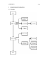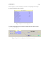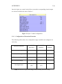
1
Gerald Villavicencio Chávez IEC 61850 DEMONSTRATION SYSTEM WITH NETCON 500 AND VAMP PROTECTION RELAYS Information Technology 2012 FOREWORD I would like to thank to all the people that have supported and helped me during my study time at VAMK and during the development of this thesis project. First of all, I would like to thank my supervisor in VAMP Oy, Olavi Vähämäki, for giving me the opportunity to make this thesis project and also for his guidance during its development. Secondly, thanks to Seppo Sauna-aho for the long explanations he gave me in relevant topics related to the implementation of the project. Also, I would like to thank Antti Virtanen, my thesis supervisor, for his support and help during my studies at VAMK and especially during the completion and documentation of my thesis project. Finally, thanks to my family, for always being there for me. Vaasa, 4.6.2012 Gerald Villavicencio VAASAN AMMATTIKORKEAKOULU UNIVERSITY OF APPLIED SCIENCES Degree Programme in Information Technology ABSTRACT Author Title Year Language Pages Name of Supervisor Gerald Villavicencio Chávez IEC 61850 Demonstration System with Netcon 500 and VAMP Protection Relays 2012 English 46 + 1 Appendix Antti Virtanen This thesis work was made in cooperation with VAMP Oy. The main purpose of this thesis was to configure the Netcon 500 RTU for implementing a demonstration system that consists in an automated network of Intelligent Electronic Devices that provide protection to substation faults and report events to a SCADA simulator using mainly the IEC 61850 protocol. The development of this thesis involves some theoretical knowledge of power generation and distribution, and familiarization with the configuration of the SPABus and IEC 61850 protocols, VAMP relays and the Netcon 500 RTU. This thesis contains the basic theory for the development of the system, an overview of the demonstration system and a configuration guide as an attachment that contains all the configuration steps of the development. The results obtained from the development process of this thesis project were satisfactory because I successfully implemented a demonstration system for training VAMP customers in the configuration of protection functions, in the utilization and configuration of the IEC 61850 and SPA-Bus protocols and in the utilization of Simple Tester for monitoring VAMP relays. Based on the results obtained, I can conclude that VAMP Oy has from now on a working and suitable environment for giving complete training courses of their protection relays. Keywords Netcon 500, IEC 61850, SCADA, substation CONTENTS 1 INTRODUCTION ......................................................................................... 8 1.1 Brief Introduction to IEC 61850 ............................................................. 8 1.2 VAMP Ltd ............................................................................................. 8 1.3 Netcontrol .............................................................................................. 9 2 BACKGROUND AND PURPOSE.............................................................. 10 3 THEORETICAL BACKGROUND ............................................................. 11 3.1 Power Generation ................................................................................. 11 3.2 Distribution Substation ......................................................................... 11 3.3 Communication Networks .................................................................... 12 3.3.1 OSI Model ................................................................................ 13 3.3.2 TCP/IP Model ........................................................................... 14 3.4 Protocols .............................................................................................. 14 3.4.1 SPA-Bus ................................................................................... 14 3.4.2 IEC 60870-5-101 ...................................................................... 15 3.4.3 IEC 61850 ................................................................................ 15 3.5 Hardware ............................................................................................. 18 3.5.1 Disconnect Switch and Circuit Breaker ..................................... 18 3.5.2 Protection Relays ...................................................................... 19 3.5.3 Remote Terminal Unit .............................................................. 19 3.5.4 SCADA .................................................................................... 19 4 DEMONSTRATION SYSTEM................................................................... 21 4.1 Introduction.......................................................................................... 21 4.2 Hardware ............................................................................................. 21 4.2.1 Components for the simulation of faults .................................... 22 4.2.2 VAMP 50 ................................................................................. 22 4.2.3 VAMP 255 ............................................................................... 23 4.2.4 Netcon 500 ............................................................................... 23 4.3 Software ............................................................................................... 25 4.3.1 Tera Term ................................................................................. 25 4.3.2 Vampset.................................................................................... 26 4.3.3 Netcon Configuration Utility (NCU2) ....................................... 26 4.3.4 Simple Tester ............................................................................ 27 4.4 Connections ......................................................................................... 27 4.5 Simple demonstration of GOOSE communication ................................ 29 4.6 Overcurrent protection implemented with IEC 61850 ........................... 30 4.7 Overvoltage protection ......................................................................... 32 4.8 Arc overcurrent protection implemented with IEC 61850 ..................... 34 4.9 Monitor and control of an SPA-Bus protection relay ............................ 36 4.10 Monitor and control of IEC 61850 protection relays ............................. 37 4.11 Results of Monitoring the IEDs with the Simple Tester ........................ 39 5 RESULTS OF THE DEVELOPMENT ....................................................... 41 6 CONCLUSIONS ......................................................................................... 42 REFERENCES ..................................................................................................... 44 APPENDICES ABBREVIATIONS AC Alternating Current ACSI Abstract Communication Service Interface ARP Address Resolution Protocol AVC Automatic Voltage Control CDC Common Data Classes CID Configuration IED Description CPU Central Processing Unit DC Direct Current DI Digital Input DNP Distributed Network Protocol DO Digital Output GOOSE Generic Object Oriented Substation Events GPS Global Positioning System GSSE Generic Substation State Events HMI Human Machine Interface ICD IED Capability Description IEC International Electrotechnical Commission IED Intelligent Electronic Device ICMP Internet Control Message Protocol ISO International Organization for Standardization NCU2 Netcon Configuration Utility NFE Network Front-End NI Network Input NPC Network Projector Protocol NTP Network Time Protocol OSI Open System Interconnection RARP Reverse Address Resolution Protocol RTU Remote Terminal Unit SCADA Supervisory Control and Data Acquisition SCD Substation Configuration Description SSD System Specification Description SCL System Configuration description Language SNTP Simple Network Time Protocol SV Sampled Values TCP/IP Transmission Control Protocol / Internet Protocol UDP/IP User Datagram Protocol / Internet Protocol VI Virtual Input VO Virtual Output XML Extensible Markup Language LIST OF FIGURES Figure 1. Distribution substation p. 12 Figure 2. OSI Layers p. 13 Figure 3. Composition of the IEC 61850 data model p. 16 Figure 4. Overview of the IEC 61850 Functionality and Profiles p. 17 Figure 5. VAMP 50 p. 22 Figure 6. VAMP 255 p. 23 Figure 7. GW 502 – Front panel ports p. 24 Figure 8. SIO 508 p. 25 Figure 9. Tera Term p. 25 Figure 10. Vampset p. 26 Figure 11. NCU2 p. 26 Figure 12. Simple Tester. p. 27 Figure 13. Connection diagram p. 28 Figure 14. Simple GOOSE communication p. 29 Figure 15. Overcurrent protection p. 31 Figure 16. Overvoltage protection p. 33 Figure 17. Arc overcurrent protection p. 35 Figure 18. Monitor and control of an SPA-Bus IED p. 36 Figure 19. Monitor and control of IEC 61850 IEDs p. 38 Figure 20. Data points obtained with Simple Tester p. 39 Figure 21. Analogue values in the Netcon 500 p. 40 8 1 1.1 INTRODUCTION Brief Introduction to IEC 61850 Since the utilization of intelligent electronic devices for the automation of power stations, customers and manufacturers have been searching for an ideal communication protocol adopted worldwide. In 1995, the International Electrotechnical Commission (IEC) started a project with sixty specialists from different countries for the creation of a future proof protocol with high interoperability between devices from different vendors. This new protocol was denominated IEC 61850. /7/ Nowadays, the IEC 61850 protocol has been implemented in power automation products by the most important manufacturers all over the world. VAMP Ltd implemented this protocol in 2008 and currently is one of the most required by customers from different countries. The successful results from the implementation of this protocol in VAMP have led into the need of having a demonstration system for training the customers in the utilization of IEC 61850 protocol and VAMP protection relays. /18/ 1.2 VAMP Ltd VAMP Ltd is a company established in Finland that specializes in protection relays, arc flash protection and measuring and monitoring units for power systems. Nowadays, VAMP products are used in nearly 80 countries to protect applications from overhead line feeders and substations to power plants and industrial power systems. All VAMP products have been developed according to the latest international standards and regulations. /17/ 9 1.3 Netcontrol Netcontrol is a Finnish company founded in 1991 and has its head office in Helsinki. This company supplies SCADA systems and related communication equipment for different applications like electric utilities, district heating plants, railway contractors, power transportation, oil & gas refining, and public or private water treatment and distribution plants. Netcontrol also offers services like support and helpdesk, system implementation, training and consultation. /12/ 10 2 BACKGROUND AND PURPOSE This thesis work was assigned to me by VAMP Oy. The purpose of this thesis was to develop a demonstration system that uses mainly the IEC 61850 protocol, and SPA-Bus protocol. This system is composed by the Netcon 500 (RTU), three VAMP protection relays (VAMP 255 and VAMP 50) and SCADA simulator software (Simple Tester). The development of this thesis work included the construction of a demonstration system, familiarization with the IEC 61850, IEC 60870-5-101 and SPA-Bus protocols, configuration process of VAMP relays for protection against substation faults and configuration process of Netcon 500 RTU for the communication between the relays and for reporting events, digital and analogue measurements to the Simple Tester software. The main concern of this thesis was to configure the Netcon 500 as a data concentrator system for the relays and as aprotocol translator between the protocol used by the relays and the protocol used by SCADA simulator. As mentioned earlier the configuration of overcurrent, overvoltage and arc overcurrent protection functions and familiarization with multiple protocols were important parts of this thesis, which were approached mainly from a practical perspective. 11 3 3.1 THEORETICAL BACKGROUND Power Generation The utilization of alternating current (AC) for the generation of electricity was a crucial factor in the development of current power generation and distribution systems. In comparison with early years when direct current (DC) was utilized, modern power generation and distribution systems can increase the voltage in power transmission lines to reduce the current, which at the same time reduces the size of conductors and distribution losses. This advantage not only was better from the economical point of view, but was also important for power transmission over long distances. /6/ The main components of a modern power generation and distribution system are generating stations, transmission lines and distribution stations. In generating stations, power is generated from other types of energy, being the most utilized worldwide: coal, natural gas, nuclear and hydroelectric. After the power is generated, large transformers are used to increase the voltage level before is transmitted over transmission lines. Transmission lines carry the power over long distances and deliver it to local substations for distribution. In local substations, voltage level is reduced to be delivered to the end-user. /6/ 3.2 Distribution Substation Distribution substations are responsible for the distribution of power to the endusers located nearby; among the end-users are industrial, commercial and residential customers. A distribution substation could be mainly composed by a transformer to step-down the voltage level, a voltage controller, busses (distribution grids) for distributing the power to different places, disconnect switches and a circuit breaker. However, in order to prevent accidents that could cause human or economic losses, protection and monitoring devices are basic components for all types of power substations. The integration of protective and monitoring devices 12 (protection relays and a SCADA system) through communication protocols constitutes an automated network to respond to real time events in order to maintain uninterrupted power services to the end-users. Figure 1 gives an overview of the power distribution process from power plants to an end-user and an overview of a distribution substation. /4; 5/ Figure 1. Distribution substation. /20, 43/ 3.3 Communication Networks One of the most important steps in the implementation of a communication network in a substation is to determine which protocol is going to be used for the communication between IEDs. There are two types of protocols for substation automation: serial-based and Ethernet based. In general terms, is difficult to determine which type is better because their benefits are based on the type of application. However, nowadays Ethernet based protocols are proving that they can perform the same job as serial protocols more efficiently. /1/ 13 3.3.1 OSI Model In the early 1980s companies realized the importance of using networking technology, which led to a fast expansion of his usage. By the mid-1980s these companies began to experience problems for the exchanging of information due to the different implementation and specification of their networks. /3/ To solve the network incompatibility issue, the International Organization for Standardization (ISO) developed the Open System Interconnection (OSI) reference model. This model established a set of standards for compatibility and interoperability among network technologies produced by companies around the world. /3/ The OSI model consists in a structure of seven layers that explains how information travels throughout a network. Figure 2 shows the layer structure of the OSI model and explain some functions of each layer. 7 Application Provides network services to application processes. 6 Presentation Provides services like character code translation, data conversion, data compression and data encryption. 5 Session Establishes, manages, and terminates sessions between applications. 4 Transport Ensures that data is delivered successfully. 3 Network Defines the path that data should take. 2 Data Link Provides reliability in the transmission of data from one node to another over the physical layer. 1 Physical Is concerned with the transmission of binary data and physical aspects of network communication. Figure 2. OSI Layers. 14 3.3.2 TCP/IP Model The TCP/IP model was created by the U.S. Department of Defense (DoD) and it was developed as a robust network capable of resisting severe war conditions. Afterwards, the TCP/IP model turned into the standard in which the Internet is based on. This model consists in 4 layers called Application, Transport, Internet and Network Access (or Link). /3/ Application layer ensures that data is packed correctly before it is passed on to the next layer. Some of the application layer protocols are File Transfer Protocol (FTP), Trivial File Transfer Protocol (TFTP), Network File System (NFS), Simple Mail Transfer Protocol (SMTP), Telnet, Simple Network Management Protocol (SNMP) and Domain Name System (DNS). Transport layer provides logical connection between a source host and a destination host and services like connection-oriented communication, byte orientation, reliability, flow control, congestion avoidance and multiplexing. Internet layer is responsible of selecting the best path through the network for packets to travel. Some of the Internet layer protocols are Internet Protocol (IP), Internet Control Message Protocol (ICMP), Address Resolution Protocol (ARP) and Reverse Address Resolution Protocol (RARP). Network Access layer makes possible the encapsulation of IP datagrams into frames for transmission purposes and maps the IP addresses to the corresponding physical addresses. /3/ 3.4 Protocols 3.4.1 SPA-Bus SPA-Bus is a fieldbus protocol used for distributed protection, control and event reporting systems. This protocol can be utilized for the communication between several slave units such as protective relays, control units and alarm units and a master unit. SPA-bus uses asynchronous serial communication (1start bit, 7 data 15 bits + even parity, 1 stop bit) and the common data transfer rate is 9600 b/s. The messages transmitted in the bus consist of ASCII characters. /16/ 3.4.2 IEC 60870-5-101 The IEC 60870-5-101 (also known as IEC-101) protocol was designed by the International Electrotechnical Commission for the supervision of power transmission and production applications. This protocol is meant to be used for the communication between SCADA and substation automation systems, and is mainly utilized in Europe. /10/ The IEC-101 protocol uses 3 layered modified OSI-model where layers 3 to 6 are implemented in the application layer (EPA-model). This protocol supports half and full-duplex communication up to 64 kbits/s and several communication configurations: point-to-point, multiple-point-to-point, multiple party line and redundant line. There are two types of communication modes for this protocols, unbalanced (master requests all data from slave) and balanced (slave device sends message spontaneously). /10/ 3.4.3 IEC 61850 IEC 61850 is the latest standard for the design of electrical substation automation prepared by the International Electrotechnical Commission’s (IEC) Technical Committee 57. The main goal of this standard is to provide interoperability between IEDs from different suppliers. In comparison with preceding communication protocols, IEC 61850 was designed to operate over modern networking technologies and has an unprecedented amount of functionalities /15/. The following are some of the important components and characteristics that make IEC 61850 unique and one of the best standards in his field: 16 Data Modelling Approach The IEC 61850 standard has a virtualized data model that consists in a structural organization of physical device, logical device, logical node, data and data attribute /15/. Figure 3 shows the class model of the ACSI. Figure 3. Composition of the IEC 61850 data model. /8, 18/ The data model also includes common data classes (CDC) that describe the type and structure of the data within the logical node. There are CDCs for status information, controllable analogue set point information, status settings, and analogue settings. /15/ 17 Communication Service Mapping The Abstract Communication Service Interface (ACSI) models of the IEC 61850 standard define services for communication or information exchanging between IEDs. These services are mapped to a sub-set of protocols and are used according to the application. Figure 4 gives an overview of the functionality and profiles of the IEC 61850 protocol. /15/ Figure 4. Overview of IEC 61850 Functionality and Profiles. /9, 22/ One of the sub-protocols more widely used is the Generic Object Oriented Substation Event (GOOSE). This protocol uses a publisher-subscriber mechanism on multicast to provide communication between IEDs. 18 Substation Description Language Substation Configuration Language (SCL) is based on the eXtensible Markup Language (XML) and describes the configurations of IEDs. Some of the SCL files are system specification description (SSD), IED capability description (ICD), substation configuration description (SCD), and configured IED description (CID). These files are constructed using the same methods and format but are used for different kind of applications. /15/ In general, SCL provides flexibility in the management of the IEDs configuration. Some of the most important benefits of this technology are that allows the storage of the configurations, enables the off-line development of the configuration files, permits the sharing of the IED configuration among users and suppliers and allows the preparation of configuration files without requiring a network connection to the IED. /15/ 3.5 Hardware There are multiple hardware components for the protection of a distribution substation, being the following the most relevant ones in the construction of this demonstration system: 3.5.1 Disconnect Switch and Circuit Breaker These two devices are utilized in power substations, although both are switches is important to realize the difference between them. Disconnect switches are used to isolate electric devices once the power has been cut-off, on the other hand circuit breakers are used to cut the power in emergency situations. Usually a disconnect switch is operated manually, while a circuit breaker will respond automatically to the trip signals. /4/ 19 3.5.2 Protection Relays Protection relays are intelligent electronic devices utilized in power generation, transmission and distribution in utility and industrial applications. Among the many protection functions they perform, some of the most relevant ones are: overcurrent, overvoltage and arc fault. In a substation, protection relays are connected to the power transmission lines for measuring current. When the values of current or voltage are not between the normal limits, the relay will emit a trip signal to perform the corresponding task (according to the relay configuration) like open a circuit breaker. /20/ 3.5.3 Remote Terminal Unit A Remote Terminal Unit is an electronic device that works as an intermediary for the communication of IEDs and a monitor and control system (SCADA). The main function of an RTU is to collect and store data from the IEDs and transmit it to a SCADA for reporting, controlling and supervision. /2/ The hardware of an RTU is basically composed by a CPU and a volatile memory, a non-volatile memory for data storing, I/O ports for the interaction with other devices and a SCADA, a power supply, a watchdog timer and real time clock. RTUs also requires software to perform their functions, some of the basic programs needed are a real time operating system, drivers for the communication with a SCADA and with IEDs, and a SCADA application for functions like scanning inputs, data processing and storing. /2/ 3.5.4 SCADA The acronym SCADA stands for Supervisory Control and Data Acquisition. A SCADA system provides remote control and management solutions in industrial processes, infrastructure processes or facility processes. /2/ A SCADA System includes the following components: 20 Human-Machine Interface (HMI) The HMI processes the data obtained from the RTU and represents it graphically to the operator. Supervisory System The supervisory system is a computer used to acquire information and perform control functions. Remote Terminal Units (RTUs) Communication network A communication network provides the necessary connections for the communication between a supervisory system and the RTUs. /2/ 21 4 DEMONSTRATION SYSTEM 4.1 Introduction The demonstration system has been essentially built and configured to provide training to VAMP customers in the utilization of IEC 61850 protocol and VAMP protection relays, however also counts with a small demonstration in the utilization of SPA-Bus protocol. The configuration process of this system was performed for: The monitoring and controlling of an SPA-Bus protection relay using the Netcon 500 and Simple Tester The monitoring and controlling of IEC 61850 protection relays using the Netcon 500 and Simple Tester A simple demonstration of GOOSE communication Overcurrent protection using the IEC 61850 protocol in its implementation Overvoltage protection Arc overcurrent protection using the IEC 61850 protocol in its implementation All the configurations for overcurrent, overvoltage and arc overcurrent faults were applied to provide effective protection to a distribution substation that ideally has one main feeder line and two outgoing feeders. Each of the feeder lines count with a disconnect switch and a circuit breaker, which are represented as objects in each of the protection relays. 4.2 Hardware The hardware used in the construction of the demonstration system includes basic components for the simulation of faults and IEDs for the protection, monitoring, and controlling of a substation. 22 4.2.1 Components for the simulation of faults Voltage transformer: This single phase transformer is used for the simulation of overvoltage faults and has a maximum output value of 28.70 VAC. Current transformer: This single phase transformer is used for the simulation of overcurrent and arc overcurrent faults, and has a maximum output value of 1.75 A. LED and light sensor: These components are used for the simulation of an arc overcurrent fault. For the light detection of the sensor is necessary that the LED has a minimum output value of 8000 lux. Toggle switch: This switch is used for the demonstration of a basic GOOSE communication between two IEDs. 4.2.2 VAMP 50 VAMP 50 (Figure 5) is a relay mainly used for current measurement, overcurrent protection and earth-fault protection; however it can be equipped with an arc sensor interface module for arc flash protection. It also can be equipped with modules for extension of DI/DO channels and various communication module adapters. This relay can communicate using the following protocols: Modbus RTU, ModbusTCP, Profibus DP, IEC 60870-5-103, IEC 60870-5-101, IEC 61850, SPA-Bus, Ethernet/IP and DNP 3.0. /19/ Figure 5. VAMP 50. /17/ 23 4.2.3 VAMP 255 The Vamp 255 (Figure 6) relay has been implemented with all the required protection stages for power distribution. This relay can measure phase and line voltages and currents, frequency, reactive and apparent power, and power factor and has support for many protocols like: IEC 60870-5-103, Modbus TCP, Modbus RTU, Profibus DP, TCP/IP, SPA-bus (slave) and optionally IEC 61850. /20/ Figure 6. VAMP 255. /17/ 4.2.4 Netcon 500 The Netcon 500 is basically composed by a connection rack and a GW 502. The rack may have place for 3, 7 or 14 cards, one of the racks is for the GW 502 and the others are to connect different types of I/O modules like SIO 508, IO 64, DI 64, DO 32 and AI 16. The rack also distributes voltage from the GW 502 to the I/O modules. /11/ Netcon GW 502 The Netcon GW 502 (Figure 7) is the central processing and communication unit of the Netcon 500 and can perform functions like communication concentration and protocol translation provided by the Network Front End (NFE) application. Protocol conversion is usually used for the communication of a control and monitor system (SCADA) and IEDs that use different protocols. The data concentrator application is used to hold data from several IEDs and allows highly efficient data communication. /13/ 24 The front panel of GW 502 includes one V.24 console port, two CPU Ethernet ports, one USB port and an Ethernet switch (four 10/100BaseT ports and one 10BaseFX port). /13/ Figure 7. GW 502 – Front panel ports. /13, 1/ The back panel of the GW 502 includes connectors for power supplies, GPS signals, multirack adapters, I/O busses and serial ports. /13/ Netcon SIO508 The Netcon SIO 508 (Figure 8) is a serial port server module for the Netcon 500. The SIO 508 card provides more serial port connectivity to the GW 502. The front panel of this card includes a V.24 console port and a 10 base-T Ethernet port and the back panel includes eight serial ports (port 2 – port 9), power inputs, I/O bus and GPS interface. /14/ 25 Figure 8. SIO 508. /14, 1/ 4.3 Software The following list of software applications have been used for the configuration of the IEDs (protection relays and RTU) and as a SCADA simulator. 4.3.1 Tera Term Tera Term (Figure 9) is an open source and free software for terminal emulation. This program emulates different types of computer terminals from DEC VT100 to DEC VT382 and supports telnet, SSH 1 & 2 and serial port connections. Figure 9. Tera Term. 26 4.3.2 Vampset Vampset (Figure 10) is a free software tool used for the configuration of VAMP relays and other VAMP products. This software also incorporates tools for analyzing data recorded by the relays. Figure 10. Vampset. 4.3.3 Netcon Configuration Utility (NCU2) NCU2 (Figure 11) is a configuration tool that can be used to configure graphically Netcon NFE/NPC products. This software also allows uploading the configuration to the electronic devices via Ethernet communication. Figure 11. NCU2. 27 4.3.4 Simple Tester Simple Tester (Figure 12) is a software tool developed by Vamp Ltd for the simulation of a SCADA system. This software permits to establish a connection with VAMP products using different kind of protocols (DNP 3.0, ModBus, SPABus, IEC 60870-5-103, IEC 60870-5-101 and EthernetIP) for gathering information and performing control functions. The testing of the IEC 61850 protocol is using other software called IEC Simple Tester. Figure 12. Simple Tester. 4.4 Connections The first connections performed in the construction of this system were the ones related to the demonstration of the protection functions. The voltage transformer was connected to the first line-to-line voltage input of both VAMP 255 relays, the current transformer was connected to the second phase input current of the VAMP 255 and the VAMP 50, and the light sensor was connected to the first arc sensor input of one of the VAMP 255 relays. This relay also had its digital inputs one and two connected to the internal control voltage through a toggle switch. 28 The cables and modules used for the connection of the protection relays and the Netcon 500 were according to the protocols utilized and the interfaces available. In order to connect any device via Ethernet to the GW 502, first is necessary to connect the CPU Ethernet port to the Ethernet switch. The communication between the GW 502 and the SIO is only via Ethernet, which means that is also required to use an RJ-45 cable (1) to connect the CPU Ethernet port of the SIO 508 and the Ethernet switch of the GW 502. For the connection of the relays that use the IEC 61850 protocol and the Netcon 500 was required to use an external Ethernet switch due to the lack of ports in the GW 502. The relay that uses the SPA-Bus protocol was connected to the serial port 2 of the SIO 508 card using an optic fiber/RS-232 module (2). The connection between the SCADA simulator and Netcon 500 was established using an RS-232 cable (3) to the serial port 6 of the SIO 508 card. The cables are numbered according to Figure 13. Figure 13 shows an overview of how IEDs are connected and the protocols they use. Figure 13. Connection diagram. 29 4.5 Simple demonstration of GOOSE communication The simple demonstration of GOOSE communication has been prepared as an introduction to the configuration of the IEC 61850 protocol and GOOSE protocol for communication between IEDs. This demonstration was implemented by configuring the IEC 61850 settings and the GOOSE settings in both VAMP 255 relays and it consists in turning on and off the LEDs A and B of a VAMP 255 configured as publisher using the digital inputs 1 and 2, the internal voltage control and a toggle switch. At the same time this publisher relays sends signals (virtual outputs 3 and 4) to the second VAMP 255 relay configured as subscriber to turn its LEDs A and B as well. Figure 14 gives an overview of the GOOSE data points connected and transmitted for this demonstration. Figure 14. Simple GOOSE communication. 30 4.6 Overcurrent protection implemented with IEC 61850 “Overcurrent protection is used against short circuit faults and heavy overloads. The overcurrent function measures the fundamental frequency component of the phase currents” /20, 54/. In VAMP relays, the protection stage will activate the start signal whenever any of the phase currents measured exceeds the user’s pick-up setting of a particular stage, and if the time elapsed since the activation of the start signal exceeds the operation time delay, the trip signal will be then activated. This protection function has three independent stages: 1 st Overcurrent Stage (I>), 2nd Overcurrent Stage (I>>) and 3rd Overcurrent Stage (I>>>) and each of them is configured separately. These three stages can be configured separately with different parameters for providing overcurrent protection for different situation faults. /20/ The demonstration of overcurrent protection in VAMP relays has been prepared to provide training in its configuration for a power distribution application. In a distribution substation, an overcurrent fault in any of the outgoing feeder lines could be solved by opening the circuit breaker of the main feeder line. However, this is not an optimal solution for real applications because that will leave the whole distributed area without power. The ideal configuration for real distribution systems consists in being able to determine and solve the fault in the specific feeder line, so it will affect as less end-users as possible. The configuration of the overcurrent protection in this system has been implemented with the most optimal approach to real applications. The two relays (VAMP 255 and VAMP 50) that are ideally connected to the outgoing feeders have been configured for 1st overcurrent protection and have as a pick-up value 1200 A. At the same time, the relay that simulates a connection to the main feeder line has been configured for the 1st and 2nd overcurrent protection. However, the 1st overcurrent protection will be blocked if an overcurrent fault is detected in any of the relays connected to the outgoing feeders; this configuration assures that the circuit breaker of the main feeder line will not open in case the fault is only in any 31 the outgoing feeders. The 2 nd overcurrent protection has been configured as a backup protection function in case that the overcurrent situation was not solved by any of the protection relays in the outgoing feeders and the current has increased continuously. The 2nd overcurrent stage has a pick-up setting of 1700 A. The configuration of the overcurrent protection includes also the GOOSE protocol in its implementation. As it can be seen in Figure 15, the signals of the 1st overcurrent stage in the relays connected to the outgoing feeder are sent via GOOSE messaging to the GOOSE subscriber to block its 1 st overcurrent stage. Figure 15 gives an overview of the configuration of the overcurrent protection. Figure 15. Overcurrent protection. 32 4.7 Overvoltage protection “The overvoltage function measures the fundamental frequency component of the line-to-line voltages regardless of the voltage measurement mode (2LL+Uo, 3LN, 1LL+Uo/LLy, 2LL/LLy)” /20, 106/. The selection of voltage measurement modes depend on the application and on the available voltage transformers (for more detailed information of the voltage measurement modes in VAMP relays refer to the VAMP 255 User Manual listed in the references). In VAMP relays, the start signal is activated whenever any of the three line-to-line voltages exceeds the user’s pick-up setting of a particular stage and if the overvoltage fault remains longer than the user’s operation time delay, the trip signal is activated. This protection function has three independent stages: 1st Overvoltage Stage (U>), 2nd Overvoltage Stage (U>>) and 3rd Overvoltage Stage (U>>>) and each of them is configured separately. These three stages can be configured separately with different parameters for providing overvoltage protection for different situation faults. /20/ The demonstration of overvoltage protection in VAMP relays has been prepared to provide training in its configuration for a power distribution application. In a distribution substation, constant voltage is guaranteed by an automatic voltage control (AVC) device. However, some problem with the normal performance of this device could cause overvoltage in the distribution system, which could cause expensive damage. Protective relays can be used as back-up devices in case of an overvoltage situation. The configuration of the overvoltage protection in this system has been implemented with the most optimal approach to real applications. Both VAMP 255 relays have been configured to provide overvoltage protection and in comparison to overcurrent and arc overcurrent protection, its implementation doesn’t require GOOSE communication. The two relays measure the voltage level of the main feeder line and the circuit breaker has been configured to open in case this level exceeds the pick-up setting. 33 Figure 16 gives an overview of the configuration of the overvoltage protection function. Figure 16. Overvoltage protection. 34 4.8 Arc overcurrent protection implemented with IEC 61850 The arc overcurrent protection is used against arc flashes. “The function is based on simultaneous light and current measurement” /20, 136/. In VAMP relays, the start signal is activated whenever any of the arc inputs is in high state, and if any of the phase currents exceeds the pick-up setting, the relay will trip immediately. This protection function has three separate stages for the different types of current inputs: ArcI> for phase-to-phase arc faults (IL1, IL2 and IL3), ArcIO1> for the phase-to-earth arc faults and ArcIO2> for phase-to-earth arc faults. The difference between ArcIO1 and ArcIO2 is that they have different residual currents as inputs: IO1 and IO2 respectively. /20/ An arc flash is not a common fault in power distribution applications; however when it happens could cause a substantial damage, fire or injury. The massive energy released could rapidly vaporize the metal conductors involved and could cause other severe explosions of devices located nearby. Nowadays, arc protection devices are a basic component of a substation considering the amount of damage that an arc flash could cause. The configuration of the arc overcurrent protection in this system has been implemented with the most optimal approach to real applications. Both VAMP 255 relays have been configured to provide protection against arc faults; however the light information signal is different in both configurations. The arc overcurrent stage has been optimized in this demonstration system by utilizing the GOOSE protocol. The relay that simulates a connection to the outgoing feeder will detect the light with the arc sensor and send this parameter via GOOSE message to the relay that is connected to the main feeder line. These relays will measure if the current input exceeds the pick-up setting, if so, they will trip and open their circuit breakers almost simultaneously. 35 Figure 17 gives an overview of the configuration of the arc overcurrent protection function. Figure 17. Arc overcurrent protection. 36 4.9 Monitor and control of an SPA-Bus protection relay The monitoring and controlling of an SPA-Bus protection relay was not one of the most important goals of this system, however it was implemented as future reference for the configuration and training of serial-based communication protocols. In order to implement this demonstration was necessary to configure the VAMP 50 relay with the SPA-Bus settings and configure the Netcon 500 for protocol translation from IEC-101 to SPA-Bus. The demonstration consists in using the IEC-101 protocol with the Simple Tester software to gather information from digital SPA-Bus items and to control a disconnect switch, which is represented in VAMP relays as object 3. The digital SPA-Bus items used in the demonstration are: Virtual Output 1 (VO1), Virtual Output 2 (VO2), Virtual Output 3 (VO3), Virtual Output 4 (VO4) and 1st Overcurrent Stage (I>). Figure 18 gives an overview of the monitoring and control of an SPA-Bus IED using Simple Tester. Figure 18. Monitor and control of an SPA-Bus IED. 37 4.10 Monitor and control of IEC 61850 protection relays The monitoring and controlling of IEC 61850 protection relays was implemented to provide training to VAMP customers in the utilization of the IEC 61850 protocol in VAMP relays and in the communication between an SCADA system and a network of IEC 61850 IEDs. In order to implement this demonstration was required to configure the IEC 61850 settings in the three VAMP relays and to configure the Netcon 500 for protocol translation from IEC-101 to IEC 61850. The demonstration consists in using the IEC-101 protocol with the Simple Tester software to gather information from digital IEC 61850 data points and to control a disconnect switch, which is represented in VAMP relays as object 3. The digital IEC 61850 data points utilized in this demonstration are different for each VAMP relay: VAMP 255 (Subscriber): 1st Arc Overcurrent Stage 1st Overcurrent Stage 2nd Overcurrent Stage Virtual Output 1 Virtual Output 2 Virtual Output 3 Virtual Output 4 VAMP 255 (Publisher): Digital Input 1 Digital Input 2 1st Arc Overcurrent Stage 1st Overcurrent Stage 38 1st Overvoltage Stage Virtual Output 1 Virtual Output 2 Virtual Output 3 Virtual Output 4 Arc sensor 1 VAMP 50: 1st Overcurrent Stage Virtual Output 1 Virtual Output 2 Virtual Output 3 Virtual Output 4 Figure 19 gives an overview of the monitoring and control of IEC 61850 IEDs using Simple Tester. Figure 19. Monitor and control of IEC 61850 IEDs. 39 4.11 Results of Monitoring the IEDs with the Simple Tester The results obtained with the Simple Tester software were partially satisfactory. It was possible to gather the state value from all the digital IEC 61850 data points and from all SPA-Bus items; however it was not possible to gather the status of current and voltage measurements (analogue data points). Respecting the control operation, it was possible to control the disconnect switch in the three relays using Simple Tester. Figure 20 shows that Simple Tester was able to read multiple data points from the IEDs. Figure 20. Data points obtained with Simple Tester. 40 Although it was not possible to gather the values from the analogue data points using the Simple Tester software, it was necessary to confirm that there was no problem with the configuration of the Netcon 500. Figure 21 shows that the Netcon 500 is receiving data from the Vamp255_Publisher relay corresponding to the phase current L2 (984 A), the voltages U12 and U23 (2789 V) and U0 (0 V). This shows that the configuration process of the analogue data points was correct; however Simple Tester is not able to read them. Figure 21. Analogue values in the Netcon 500. 41 5 RESULTS OF THE DEVELOPMENT Almost all objectives of the development process of this thesis project were achieved successfully. I managed to build a demonstration system that will be used for the training of VAMP customers in: The configuration of VAMP relays for overcurrent, overvoltage and arc overcurrent protection functions. The configuration of SPA-Bus and IEC 61850 protocols in VAMP relays. The utilization of GOOSE communication between VAMP relays against overcurrent and arc overcurrent faults. The monitoring of digital data points and the manipulation of objects in VAMP relays through the Netcon 500 RTU using Simple Tester and using the IEC 60870-5-101 as master protocol. Finally, I successfully prepared a configuration guide that contains all the necessary steps for the configuration of the Demonstration System. The configuration guide is the Appendix 1 of this document. 42 6 CONCLUSIONS The completion time of this thesis project assigned by VAMP was approximately five months, during this time I implemented almost all the requirements specified for the project. The successful implementation of this thesis project represents that VAMP Oy has from now on a working environment for giving a complete training to their customers in the utilization and configuration of VAMP relays and especially in the utilization of the IEC 61850 protocol, which was the main objective of this project. As mentioned before, there was one requirement that was not fulfilled. The task consisted in showing the analogue measurements (current and voltage) in the Simple Tester software. Even though I was not able to complete this task, I determined that the problem was the communication between the Netcon 500 and Simple Tester; apparently the Simple Tester was not implemented correctly for gathering analogue data points through the Netcon 500. REFERENCES /1/ Arash Shoarinejad. GE Energy Network Reliability Products and Services. Communication Protocols in Substation Automation and SCADA. http://www.atrakenergy.com/Resources/PSC-2004.pdf /2/ Boyer Stuart, A. 1993. SCADA: Supervisory Control and Data Acquisition. Instrument Society of America, Research Triangle, NC. /3/ CCNA 1. CISCO. Accessed: 8.8.2011. http://cisco.oamk.fi/materiaalit/vanha_historia/v3.1/sem1/chapid=null/rloid=null/ rioid=null/knet/311053022401441/coursetoc.html /4/ Electrical substation. Wikipedia. Accessed: 5.8.2011. http://en.wikipedia.org/wiki/Electrical_substation /5/ Electric power distribution. Wikipedia. Accessed: 5.8.2011. http://en.wikipedia.org/wiki/Electricity_distribution /6/ Electric power transmission. Wikipedia. Accessed: 5.8.2011. http://en.wikipedia.org/wiki/Electric_power_transmission /7/ IEC 61850-SER ed2.0. Technical Committee 57, International Electrotechnical Commission. /8/ IEC 61850-7-2 ed2.0. Technical Committee 57, International Electrotechnical Commission. /9/ IEC 61850-8-1 ed2.0. Technical Committee 57, International Electrotechnical Commission. /10/ IEC 60870-5-SER ed1.0. Technical Committee 57, International Electrotechnical Commission. /11/ Netcon 500. Netcontrol Oy. Accessed: 20.8.2011. http://www.netcontrol.fi/index.php/download_file/view/174/512/ /12/ Netcontrol Oy. Accessed: 1.8.2011. http://www.netcontrol.fi/ /13/ Netcon GW502. Netcontrol Oy. Accessed: 20.8.2011. http://www.netcontrol.fi/index.php/download_file/view/181/512/ /14/ Netcon SIO508. Netcontrol Oy. Accessed: 20.8.2011. http://www.netcontrol.fi/index.php/download_file/view/191/512/ /15/ Ralph Mackiewicz. SISCO, Inc. Technical Overview and Benefits of the IEC 61850 Standard for Substation Automation. Accessed 18.8.2011. http://www05.abb.com/global/scot/scot313.nsf/veritydisplay/ 04519389e504d7ddc12576ff0070704d/$file/ 3bus095131_en_iec61850_overview_and_benefits_paper_general.pdf /16/ SPA-Bus Communication Protocol V2.5 Technical Description. ABB Oy. Accessed 15.8.2011. http://www05.abb.com/global/scot/scot229.nsf/veritydisplay/ 811733b652456305c2256db40046851e/$file/spacommprot_en_c.pdf /17/ VAMP Oy. Accessed: 1.8.2011. http://www.vamp.fi/ /18/ VAMP Oy. 2007. VAMP implements IEC 61850. Accessed 10.8.2011. http://www.vamp.fi/Customer%20journals/Protection%20and%20control%202_2 007.pdf /19/ VAMP 50 User Manual. VAMP Oy. Accessed 19.8.2011. http://www.vamp.fi/Manuals/English/VM50.EN011.pdf /20/ VAMP 255 User Manual. VAMP Oy. Accessed 19.8.2011. http://www.vamp.fi/Manuals/English/VM255.EN024.pdf APPENDIX 1 1(36) Demonstration System – Configuration Guide VAMP Ltd / Gerald Villavicencio / 5.10.2011 APPENDIX 1 2(36) CONTENTS 1 INTRODUCTION ....................................................................................... 3 2 CONNECTION DIAGRAM ....................................................................... 3 3 CONFIGURATION PROCESS.................................................................. 4 3.1 Flowchart .............................................................................................. 4 3.2 Configuration of VAMP Relays ........................................................... 5 3.2.1 Configuration of Object 1 and Object 3 ................................... 5 3.2.2 Configuration of Protection Functions..................................... 7 3.2.3 Configuration of IEC-61850 ................................................... 11 3.2.4 Configuration of SPA-Bus ...................................................... 16 3.3 Configuration of Netcon 500 .............................................................. 17 3.3.1 Basic Settings .......................................................................... 17 3.3.2 Configuration of NFE File ...................................................... 20 3.3.3 Uploading of NFE file ............................................................. 35 APPENDICES APPENDIX 1 1 3(36) INTRODUCTION This configuration guide intends to cover all the necessary steps for the configuration of the demonstration system. In the most general terms, the configuration process is divided into the configuration of VAMP relays and the configuration of Netcon 500. 2 CONNECTION DIAGRAM In order to start the configuration process is necessary to have a physical overview of the demonstration system. The following diagram shows how the IEDs of the demonstration system have been connected after they have been configured. Figure 1. Connection Diagram. This diagram also contains the following fundamental information for the configuration of the Netcon 500: ports utilized in the SIO 508 and IP addresses of the GW 502, SIO 508 and protection relays. APPENDIX 1 3 3.1 CONFIGURATION PROCESS Flowchart 4(36) APPENDIX 1 3.2 5(36) Configuration of VAMP Relays The configuration process of VAMP relays is divided into configuration of protection functions and configuration of IEC 61850 and SPA-Bus protocols. All configurations for VAMP relays were performed using the Vampset version 2.2.76. 3.2.1 Configuration of Object 1 and Object 3 The configuration of a circuit breaker (object 1) and a disconnect switch (object 3) are different in power distribution applications. The circuit breaker is configured to open immediately when a fault is detected and the disconnect switch is configured to be operated manually when there is no load. To open the circuit breaker automatically is necessary to create logics to connect the trip signals of the protection functions to a virtual output using an OR gate. Figure 2. Logics for the configuration of the circuit breaker. APPENDIX 1 6(36) Once the logics are created, in the Objects menu the corresponding virtual outputs are selected to define the states of object 1. Figure 3. Object 1 control configuration. To operate the disconnect switch is required to connect the object states to virtual outputs using an RS flip-flop. Figure 4. Logics for the configuration of the disconnect switch. APPENDIX 1 7(36) Once the logics are created, in the Objects menu the corresponding virtual outputs are selected to define the states of object 3. Figure 5. Object 3 control configuration. 3.2.2 Configuration of Protection Functions The following table shows the configuration stages enabled and configured for each relay: VAMP 255 VAMP 255 VAMP 50 Subscriber Publisher Publisher 1st Overvoltage Stage (U>) x x - 1st Overcurrent Stage (I>) x x x 2nd Overcurrent Stage (I>>) x - - Arc Overcurrent Stage x x - Network Input Arc Sensor 1 (NI) (S1) Protection Function *Arc Input in use - Table 1. Overview of protection stages enabled in the protection relays. APPENDIX 1 8(36) With the exception of arc overcurrent stage, the protection stages enabled in more than one relay have been configured with the same parameters. As it can be seen from the table, VAMP 255 subscriber and VAMP 255 publisher have different arc input parameter. In the Scaling menu, set the scaling values for current and voltage transformers (CT primary 1000 A, CT secondary: 1 A, VT primary: 10000 V and VT secondary: 50 V). These values are suitable considering that the maximum input current in the demonstration system is approximately 1.75 A and the maximum input voltage is approximately 28.70 VAC. Figure 6. Scaling menu. APPENDIX 1 9(36) There are two important and common settings in the configuration of the overvoltage, overcurrent and arc overcurrent protection stages. These two settings are to enable the stage and to set the pick-up setting. The necessary parameters for the protection functions are configured in the corresponding menus. Figure 7. 1st Overvoltage Stage menu. The configuration of the 1 st overcurrent stage also requires defining the delay curve family and the delay type. These parameters were set to Definite Time (DT) in this system. Figure 8. 1st Overcurrent Stage menu. APPENDIX 1 10(36) Figure 9. 2nd Overcurrent Stage menu. The configuration of the arc overcurrent stage also requires to set a third parameter called arc input in use. As it is shown in Table 1, this parameter is Network Input (NI) in the VAMP 255 Subscriber and Arc Sensor 1 (Arc1) in the VAMP 255 Publisher. Figure 10. Arc Overcurrent Stage menu. APPENDIX 1 11(36) 3.2.3 Configuration of IEC-61850 The configuration of the IEC 61850 protocol in the protection relays starts with setting a descriptive IED name in the IEC 61850 main config menu. The names assigned to the relays for easy recognition are: Vamp255_Publisher, Vamp255_Subscriber and Vamp50. Figure 11. IEC 61850 main configuration menu. The next step is to set the network parameters and select IEC 61850 as Ethernet port protocol. The network mask and gateway address are the same for all relays. Figure 12. Protocol configuration menu. APPENDIX 1 12(36) For the utilization of the IEC 61850 data points, is necessary to set “Yes” in the “Dataset 1” column and in the “In use” column. Due to the small amount of data points required, only the Dataset 1 has been used in all relays. Figure 13. IEC 61850 data map menu. The configuration of the Buffered Report Control Block 1 is performed in the IEC 61850 BRCB configuration menu. The parameters for Dataset and Report ID can be left as default because they are names utilized by the standard and are easy to recognize, however the buffer overflow option should be set to “No”. Figure 14. IEC 61850 BRCB configuration menu. APPENDIX 1 13(36) The configuration of the GOOSE communication can be divided into publisher configuration and subscriber configuration. All options related to the configuration of GOOSE communication are found under the GOOSE menu. Publisher Configuration In the GOOSE configuration menu, it is required to enable the publisher function, assign a MAC address and assign an application ID. The MAC address is a common parameter for publishers and subscriber and the application ID must be different for each publisher. Figure 15. GOOSE configuration menu of VAMP 255. Figure 16. GOOSE configuration menu of VAMP 50. APPENDIX 1 14(36) In the GOOSE GCB1: DATA POINTS menu is possible to select the signals to be transmitted to the subscriber relay. Once all the signals have been selected all should have status “OK”, if not the signal has not been enabled in the IEC 61850 data map menu. Figure 17. GOOSE Publisher configuration menu of VAMP 255. Figure 18. GOOSE Publisher configuration menu of VAMP 50. Note: The indexes mapped to signals in the GOOSE Publisher Data Set are important parameters for the configuration of the subscriber function. APPENDIX 1 15(36) Subscriber Configuration In the GOOSE configuration menu, the subscriber function should be enabled and the MAC address assigned must be equal to the utilized in the configuration of the publisher relays. Figure 19. GOOSE Subscriber configuration menu of VAMP 255. In the GOOSE Subscriber: DATA POINTS menu, it is possible to set the required parameters to receive the signals. These parameters are the application ID of the publisher configurations and the data index mapped to signals in the GOOSE publisher data sets. Figure 20. GOOSE Subscriber Data Points menu of VAMP 255. Note: The signals received by the GOOSE subscriber are mapped to network inputs (NI). APPENDIX 1 16(36) 3.2.4 Configuration of SPA-Bus In the PROTOCOL CONFIGURATION menu, the SPA-BUS protocol must be selected as remote port protocol. Figure 21. Protocol configuration menu. In the SPABUS CONFIGURATION menu, the SPA-Bus settings are left as default. Figure 22. SPABUS Configuration menu. APPENDIX 1 3.3 17(36) Configuration of Netcon 500 The configuration of the Netcon 500 is divided into basic settings, network settings and configuration of the NFE file. It is important to mention that the Netcon 500 contain many features that can be enabled or configured, however this guide is focusing only in the necessary settings for the configuration of the demonstration system. 3.3.1 Basic Settings For configuring the basic settings of the Netcon 500 is necessary to connect the console cable to the console port of the GW 502 and use the Tera Term program. Figure 23. Serial port parameters to connect to the GW 502 card. Note: The COM port number may not be the same. APPENDIX 1 18(36) Once the connection has been established, it is required to log in to apply any changes to the settings. The login name is – the commonly utilized in Linux systems – root and the password is vamp. Figure 24. Login Settings. The hostname can be modified in the hostname file. This file has the following path: /etc/conf.d/hostname. Figure 25. Hostname file. APPENDIX 1 19(36) The network settings of the GW 502 can be modified in the net file, which has the following path: /etc/conf.d./net/. Figure 26. Network settings of GW 502. The only basic configuration that needs to be applied to the SIO 508 card is to modify the network settings: IP address and network mask. This configuration is performed by connecting the console cable to the SIO 508 card and using the Tera Term. The serial port settings for the SIO 508 console port are: 9600 baud rate/8 data bits/no parity/1 stop bit/no flow control. Figure 27. Network settings in SIO 508. APPENDIX 1 20(36) 3.3.2 Configuration of NFE File The first step in the configuration of the NFE file is to add the Netcon 500 (GW 502) and the SIO 508. New devices are added by right-clicking on NETCON and left-clicking on the corresponding names. Figure 28. Add Netcon 500 device. Figure 29. Add SIO 508 device. Once the devices are added, the software will display them with their corresponding ports. The TCP/IP port shown in the Netcon 500 device may be deleted because it won’t be needed for this specific type of configuration. Figure 30. Delete TCP/IP port. APPENDIX 1 21(36) The configuration of the Netcon 500 device starts by adding a virtual port. A new virtual port is added by right-clicking on the device name. Figure 31. Add virtual port. When a virtual port is added, the communication protocol used for this port must be selected. In the Port tab, select IEC 61850/m. Once this protocol has been selected, the Channel backup and IEC61850/m tabs will appear next to the Port tab. However any settings are changed in these two tabs. Figure 32. Select IEC 61850/m protocol. APPENDIX 1 22(36) For virtual ports mapped to the IEC 61850 protocol is required to add a station. Stations hold further and fundamental information of an IED that uses the IEC 61850 protocol. A new station is added by right-clicking the virtual port. Figure 33. Add a station. Once a station is added, some configurations must be performed in the IEC61850/m tab and in the I/O settings tab. In the IEC61850/m tab, the first step to perform is to import the ICD file. After opening the file to be imported, three dialog boxes will appear. The first dialog box asks if you want to select more files in other directories, which should be answered with a “no”. The second dialog box will show the path of the ICD file that is being imported, is just required to press the “ok” button. Finally, the third dialog box will give the option to add a description. If the name of the ICD file is descriptive enough, there is no needed to add a description. Figure 34. First dialog box. APPENDIX 1 23(36) Figure 35. Second dialog box. Figure 36. Third dialog box. When the ICD file has been successfully imported, select the ICD file just imported in the Configuration option. In the station type option, select “Buffered reporting with predefined dataset”, as report address select the option related to Buffered Report Control Block 1 and as report data set select Data Set 1. Figure 37. Settings of the ICD file. APPENDIX 1 24(36) Once the settings have been applied correctly in the IEC61850/m tab, the IEC 61850 data points will be listed in the I/O settings tab. Figure 38. IEC 61850 data points. However, in order to be able to manipulate remotely a disconnect switch (object 3) is necessary to add a command. This new command is added by selecting the I/O points only option, and adding the following object address: - Vamp255_SubscriberRelay/Obj3CSWI3$CO$Pos$Oper Instead of writing this object address is easier to drag a similar object address and delete the part that is no needed. Figure 39. Adding a command for the manipulation of object 3. APPENDIX 1 25(36) Note: The configuration for the other two relays that use the IEC 61850 protocols is basically the same. From the connection diagram is seen that the ports for the connection of the physical media of the Spacom protocol and the IEC-101 telecontrol protocol are in the SIO 508. This requires adding two more virtual ports for these two protocols for the internal communication between the SIO 508 and the GW 502. Once a new virtual port is added, select Spacom protocol and enable the Virtual Ethernet port option. Also, is necessary to set the IP address of the SIO 508 and assign a port number. Figure 40. Virtual port settings for SPA-Bus protocol. In the Channel tab, is recommended to set the parameters Timeout value to 10 and Max retries to 1. Also, the double commands option has to be enabled. Figure 41. Channel settings for the virtual port of the SPA-Bus protocol. APPENDIX 1 26(36) In the Priority tab, the recommended settings for the poll time priorities are 1, 3, 10 and 3600 seconds. Figure 42. Priority settings for the virtual port of the SPA-Bus protocol. As in the configuration of the IEC 61850 protocol, it is also necessary to add a station to hold further information of the Spacom protocol. Once a new station is added to the virtual port, in the Type option select VAASAE. Figure 43. Settings for the station of the SPA-Bus protocol. APPENDIX 1 27(36) In the I/O Settings tab, enable the data points and set the corresponding spacom channel, spacom code, spacom index and count. Figure 44. I/O settings for the SPA-Bus protocol. Note: The count parameter of Digital Output 1 is 2 because this data point refers to the disconnect switch, and this component can have two states: open and close. In the Events tab, set the event numbers for each of the data points on and off events. Figure 45. Events settings for the SPA-Bus protocol. APPENDIX 1 28(36) The configuration of the IEC-101 protocol is divided into the configuration of basic parameters and configuration of the cross reference, which is fundamental for the protocol translation. Add a new virtual port and in the Port tab change the default port and channel to 110 and select the protocol IEC-101/s. Also, is necessary to set the IP address of the SIO 508 and assign a port number. Figure 46. Virtual port settings for IEC-101 protocol. APPENDIX 1 29(36) In the IEC-101/s tab change the parameters for link address, link address size, common address size and IOA size. Also, the link acknowledgement type is short fixed and the data priority is Class1. The rest of the parameters are left as default. Figure 47. Basic settings for the IEC-101 protocol. APPENDIX 1 30(36) In the Channel / Commonaddress tab, add the native channels and common addresses of all stations. Also, select the option Use version 2 (XR2). Figure 48. Channel definition for the IEC-101 protocol. APPENDIX 1 31(36) In the Cross-reference (XR2) tab, it is recommended using consecutive host (address index) numbers for the common data types and is also preferable to change the default host address of the station mainline status. Also, is necessary to enable all data points and the station mainline status and change the host type of the command added from single command to double command. Figure 49. Cross-reference configuration for Vamp_Subscriber. Note: The configuration process for the cross reference of channels 102 and 103 is basically the same. APPENDIX 1 32(36) The configuration of channel 104 is also similar to the configuration of the previous channels. The difference is that the data point related to the command for the operation of object 3 will have two parameters: 73O1 (open state) and 73O2 (closed state). However, as it is shown in Figure 50 is only necessary to enable and configure the data point mapped to the open state. Figure 50. Cross-reference configuration for Vamp50. The final important step is to configure the ports of the SIO 508. From the connection diagram, it is known that port 2 is used for the communication with the Spa-Bus protocol and port 6 is used for the communication with the IEC-101 protocol. In the Port tab of the port 2, select 7 data bits and even parity. Figure 51. Settings for the SPA-Bus protocol port. APPENDIX 1 33(36) In the Remote Port tab of the port 2, set the IP address of the GW 502 and set the local port assigned to the virtual port of the Spa-Bus (Spacom) protocol. Figure 52. Settings for the SPA-Bus protocol remote port. In the Port tab of the port 2, select 8 data bits and none parity. Figure 53. Settings for the IEC-101 protocol port. APPENDIX 1 34(36) In the Remote Port tab of the port 2, set the IP address of the GW 502 and set the local port assigned to the virtual port of the Spa-Bus (Spacom) protocol. Figure 54. Settings for the IEC-101 protocol remote port. APPENDIX 1 35(36) 3.3.3 Uploading of NFE file Once the NFE file has been configured, this file must be uploaded to the Netcon 500. The uploading process of the NFE file is via Ethernet communication, which means that is necessary to set a suitable IP address and network mask for the computer. In the Telnet menu option of the NCU2, enable the restart automatically after upload option and set the IP address and password (nematic). Then, select the configuration that you want to upload (Netcon 500 or SIO 508) and press the button PC selected –> NFE. Figure 55. Uploading the NFE File to the GW 502. APPENDIX 1 36(36) Figure 56. Uploading the NFE File to the SIO 508. The uploading process to the SIO 508 card will show a “restart failed” message, however this is a problem of the NCU2 software and can be ignored. APPENDICES APPENDIX 1: Cross-reference configuration for Vamp255_Subscriber APPENDICES APPENDIX 2: Cross-reference configuration for Vamp255_Publisher APPENDICES APPENDIX 3: Cross-reference configuration for Vamp50 APPENDICES APPENDIX 4: Cross-reference configuration for SPA-Bus protocol APPENDICES APPENDIX 5: Logics of Vamp255_Subscriber relay APPENDICES APPENDIX 6: Logics of Vamp255_Publisher relay APPENDICES APPENDIX 7: Logics of Vamp50 relay