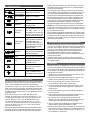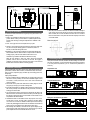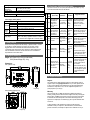
1
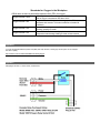
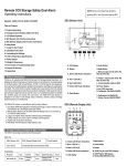
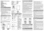
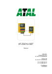
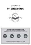
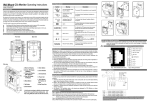
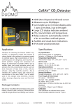
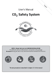
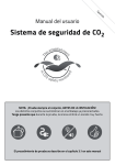
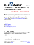
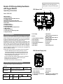
NOTE: Remove Air Intake Plug (N) before
Remote CO2 Storage Safety Dual Alarm
with Oxygen Monitor
Operating Instructions
powering SEU. Use Plug when cleaning SEU.
SEU (Sensor Unit)
A
B
Model: RAD-0200
O
Table of Contents
1. Product Instructions
2. Package Content Check & Main Unit View
3. LCD Display Symbol
4. SEU (Sensor Unit) Function Instructions
5. RDU (Remote Display Unit) Function Instructions
6. Safety Notes
7. Caring For Product
8. Installation Instructions
9. Customizing Settings
10. CO2 & O2 & Temperature Specifications
11. Relay Outputs
12. Weight & Dimensions
13. Fault Codes & Troubleshooting Guide
13. Support & Warranty
C
D
E
F
G
H
I
N
|
M
1. Product Instructions
A. LCD display
Thank you for selecting the RAD-0200 CO2 and O2 Monitor. It is designed to
detect the presence of carbon dioxide and oxygen in the ambient air to protect
people in confined spaces. High concentrations of CO2 or low concentrations
of oxygen in confined spaces are dangerous, and may lead to health problems
ranging from headaches and fatigue to asphyxiation and death.
The RAD-0200 is widely used to protect workers and employees in CO2
storage areas, breweries, wineries, cellars, beverage dispensing areas, and
fast food outlets. It has both audible and visual alarms which activate when
CO2 or O2 concentrations reach user-defined levels. Detection of high levels
of CO2 will also activate 2 relays that could be used for a fan or air-conditioning
system to ventilate the confined space, and reduce CO2 concentration and
add O2 concentration in the area.
B. Buzzer
The RAD-0200 CO2 & O2 Monitor is cost-effective and has many features:
1. Dual Beam NDIR (Non-Dispersive Infrared) technology is used to
measure CO2 concentration up to 50,000ppm (parts per million) and
electrochemical technology to measure O2 concentration up to 30%.
2. With the SEU (Sensor Unit) and RDU (Remote Display Unit), it can
connect multiple RDUs for safety notices.
3. Large LCD display clearly indicates ambient CO2& O2 concentrations.
4. Relay outputs can control a fan to ventilate confined spaces.
5. Audible and visual alarm indications.
6. IP65 Water Proof Protection of SEU (Sensor Unit).
Z
L
C. Green LED (Power indication)
D. Red 1 LED( AL1 )
E. Red 2 LED( AL2 )
F. Yellow LED( Fault indication)
G. Reset Button
H. Enter Button
K
J
I. Mode Button
J. Relay 2 output (red & white: NO,
Blue & white: NC)
K. Relay 1 output (red & white: NO,
Blue & white: NC)
L. Communication Cable to RDU
M. Power Supply
N. CO2 entry
O. O2 entry
Z. Gas Calibration Port
RDU (Remote Display Unit)
P
Q
R
S
T
U
V
2. Package Content Check & Main Unit View
The RAD-0200 package comprises the following parts:
W
Main Unit:
SEU( Sensor Unit)
RDU (Remote Display Unit)
Panel holders
User manual
8 meters (26 feet) communication cable
Accessories:
Plug lock
1 pcs
Screw
10pcs
Nail cable clip
10 pcs
Warning signs
2 pcs
Expansion
plug
10 pcs
Y
X
P. Green LED (Power indication)
U. Mode Button
Q. Red 1 LED (AL1 )
R. Red 2 LED ( AL2)
S. Yellow LED ( Fault indication)
T. LCD display
V. Enter Button
W. Buzzer
X. RJ45 Plug for next RDU (Output)
Y. RJ45 Plug for SEU (Input)
3. LCD Display Symbol
Symbol
Meaning
Description
CO2
Concentration ppm Ambient CO2 concentration
(Parts Per Million)
O2 Concentration
Ambient O2 concentration
Alarm
Alarm icon
Diagnostics
CO2/O2 First
Alarm level
CO2/O2 Second
Alarm level
Calibration
Recover Factory
Setting
ESC
Test communications between
the SEU and RDU
Relay 1 will be triggered when the
CO2 concentration exceeds the
first alarm level or O2
concentration drops below the
first alarm level, the Red 1 LED
will flash, and buzzer will sound.
Relay 2 will be triggered when
CO2 concentration exceeds the
second alarm level or O2
concentration drops below the
second alarm level. The Red 1 &
Red 2 LEDs will flash, and the
buzzer will sound.
Calibrate the CO2 / O2 sensors
when the accuracy deviates from
the actual concentration.
Recover factory default settings
and cancel customized settings.
Indicate the CO2 leakage once
the CO2 level is above the
second alarm level.
Hi
The CO2 concentration is above
5%, or the O2 concentration is
lower than 30%.
Fan
If CO2 > CO2 Alarm Level or
O2<O2 Alarm Level, fan will run.
triggered. When CO2 concentration drops below the first alarm level, or O2
concentration raises to the first alarm level, the red 1 LED will stop blinking
and the buzzer will stop beeping.
If the concentration of CO2 continues to rise above the second alarm level,
or the concentration of O2 drops below the second alarm level, the red 1 and
red 2 LED’s will both flash together, the tempo of the buzzer will increase,
and the second relay will be triggered. When the CO2 concentration drops
below the first alarm level the red 1 and red 2 LED’s will stop blinking, and
the buzzer will stop beeping. However, the yellow FLT LED will stay on to
show an event has occurred until the RAD-0200 is restarted with the reset
button RAD-0200 or the AC adapter is unplugged and reconnected.
The green LED will light continuously when the power is normally supplied.
Warning: If the ambient CO2 concentration reaches the second alarm level
on SEU & RDU, there will be a safety notice “ESC” displayed on the LCD.
Careful action, such as ventilating the space, must be taken before entering
the room where the SEU is placed.
If the communication cable between the SEU & RDU isn’t connected properly,
the fault LED on the SEU will blink. To fix this, reconnect the cable. If the cable
is accidently inserted into the output port on the RDU, after one minute “Er7”
will flash on the LCD. Unplugging the cable and plugging it into the Input port
will normally correct the problem.
5. RDU (Remote Display Unit) Function Instructions
The RDU (Remote Display Unit) should be placed outside the CO2 storage
room during use. The RDU is connected to the SEU with a CAT5 cable. An 8
meter (26 ft.) cable is supplied, although up to 3 daisy-chained RDUs over 76
meters (250 ft.) using CAT5 cable has been tested. The RDU should be
placed where it can be conveniently observed before entering the room
where the SEU is located. The RDU is a repeater, and displays the
measurements made by the SEU on an easy-to-read digital LCD along with
important safety information.
The RDU has “DIAG” function. The “DIAG” can test the communication
between the SEU and RDU. Resetting the RAD-0200 CO2 and O2 Monitor is
only available from SEU.
6. Safety Notes
Warning: Your safety is very important to us. To ensure to use the product
correctly and safety, please read these warnings and the entire User Manual
before using the product. Otherwise, the protection provided by the equipment
may be impaired. These warnings provide important safety information and
should be observed at all times.
1. Handle the device carefully; do not subject the product to impact or shock.
Otherwise, this may cause the accuracy to drift.
4. SEU (Sensor Unit) Function Instructions
2. Do not place the unit or the adaptor near a heat source. Heat can cause
distortion of the unit, which may result in an explosion or fire.
The SEU (Sensor Unit) should be placed in a room where the CO2 is likely to
accumulate or O2 reduced, such as a room where CO2 canisters or tanks are
stored. The large LCD displays the ambient CO2 & O2 concentration.
3. Do not touch the exposed electronic circuitry of the device under
any circumstances, as there is danger of electric shocks.
The SEU has the “DIAG”, “AL1”, “AL2”“CALI”, “ReFactSet” function. The
“DIAG” function executes communication tests between the SEU and RDU.
The user can do the calibration under the “CALI” mode when necessary. If
data-setting is done incorrectly, the user can use the “ReFactSet” back to the
original factory setting.
There are two alarm levels: “AL1” and “AL2”. Both alarm levels are
adjustable. The first alarm level of CO2 can be set to 5,000ppm, 1%, 1.5%,
2%. The default first alarm level is 1.5%. The first alarm level of O2 can be
set to 18%, 18.5%, 19%, 19.5% or 20%. The default first alarm level is
19%.The second alarm level of CO2 can be set to 1.5%, 2%, 2.5%, 3%,
3.5% or 4% CO2. The default second alarm level is 3%. The second alarm
level for O2 can be set to 16%, 16.5%, 17%, 17.5% or 18%. The default
second alarm level for O2 is 17%.
When the RAD-0200 CO2 &O2 Monitor detects CO2 concentration exceeds
the first alarm level or O2 concentration drops the first alarm level, the red 1
LED will blink and the buzzer will sound intermittently, and the relay will be
4. Use only the included power adaptor. Improper power adaptors or power
sources can cause serious damage to the product, or result in injury or
death to the user.
5. Use the “DIAG” function to verify the communication between SEU and
RDU works normally.
6. Make sure that the power adaptor is secured tightly by a plug lock so the
power adapter cannot be disconnected accidently or by hand.
7. Do not enter into the room directly if there has safety notice “ESC”
displayed on the LCD of SEU & RDU. Careful and protective action must
be taken before entering the room where the SEU is installed.
8. Take care of cable connection between SEU and RDU. Make sure the
cable from SEU is connected into the INPUT port of RDU.
9. Ensure the external power supply to a ventilation fan is tested while the
relay is working. If there has no power to the fan, the relay will not turn it on,
which may result in potentially dangerous high CO2 concentration or low
O2 concentration in a confined space.
Power Supply
for fan
Fan for
Ventilation
SEU (Sensor unit)
RDU
Display
8m(26ft) comm. cable
Power
Adapter
Door
RDU
Display
gas tanks
7. Caring For the Product
To receive the maximum benefit from using this product, please observe the
follow guidelines.
1. Repair - Do not attempt to repair the product or modify the circuitry by
yourself. Please contact your local dealer or a qualified repairman if the
product needs servicing, including the replacement or calibration of the
sensors.
to the 2nd/3rd RDU
(optional,daisy chain)
7. When the power has been connected, The SEU and the RDU will begin to
work. Please use the “DIAG” function to verify the communication between
SEU and RDU, the four LED’s will blink and buzzer will sound on SEU &
RDU. Communication is ready when the information displayed is the same
on the SEU & RDU.
Mount the plug lock
2. Note -- The oxygen sensor must be replaced every 3 years.
3. Cleaning - Disconnect the power before cleaning. Clean with a damp cloth
only. Do not use liquid cleaning agents such as benzene, thinner or
aerosols, as these will damage the device.
4. Maintenance – We recommend testing the communication between the
SEU and RDU under the ‘DIAG” function to verify the SEU and RDU are
working properly. If the four LED’s blink and the buzzers sound
simultaneously, it indicates that SEU and RDU work normally.
When the LCD displays a safety icon “ESC”, please take immediate
protective action to check if a CO2 leak has occurred. We suggest a
calibration and thorough function check at least yearly to make sure that
the RAD-0200 CO2 and O2 Monitor is working properly.
8. Installation Instructions
Please carefully take out the SEU (Sensor Unit), RDU (Remote Display Unit),
panel holders, network cable connector, communication cable, user manual,
plug lock, screws, expansion plugs, nail cable clips, and warning poster from
the package.
Step-by-Step Installation:
1. Choose a suitable location to install the SEU. Fix a panel holder on the wall
with the four screws (included); the recommend installation height is about
0.45 meters (1.5 feet) from the floor and as close to the manifolds and
valves as possible.
2. Put the SEU on the panel holder. Remove the Air Entry Plug from the air
entry port (N). Save plug for use when cleaning SEU.
3. Fix another panel holder in a suitable location outside the monitored space
with screws (included). Push the RDU onto the panel holder, and stick the
warning poster next to RDU.
4. The communication cable is pre-wired to the SEU. Route the cable to the
RDU and fixed the communication cable to the wall by nail cable clips, and
then plug the cable into the input port on the RDU. Communication is now
ready between the SEU and RDU.
5. The RAD-0200 CO2 and O2 Monitor has two relay outputs: one is for AL1
and the other is for AL2. The relay cable is pre-wired to the SEU. Relays
can control a fan or blower to ventilate monitored space when necessary
and the relay will be triggered when the CO2 concentration exceeds the first
alarm level or O2 concentration drops below the first alarm level.
6. After finishing the installation, Connected the AC power adapter into the
electrical supply outlet. Mount the Plug lock by expansion plugs so that the
power adapter cannot be disconnected without use of tools.
9. Customizing Settings
Once power has been connected, the SEU and RDU will begin to monitor the
CO2 & O2 concentration. In order to the get the timely alarm safety information
or to meet personal requirements, you can customize the parameters as
necessary.
Temperature ºC/ºF:
1. Press “Enter” to switch between ºC and ºF temperature.
Using the DIAG function:
PRESS
PRESS
MODE
ENTER
1. Press Mode until the “DIAG” icon flashes
2. Press Enter, the four LED’s will blink on the SEU and the buzzer will sound
3. The four LED’s will blink and buzzer will sound simultaneously on the RDU
Setting the CO2 First Alarm parameter:
PRESS
PRESS
MODE
ENTER
1. Press Mode until the “AL1” icon flashes
2. Press Enter. The “AL1” icon will show on the LCD
3. Press Mode to go through 5,000ppm, 1%, 1.5%, 2% CO2 alarm levels
4. Press Enter again to save the setting
Setting the CO2 Second Alarm parameter:
Using the O2 CALI function:
“ZEr” Calibration means the SEU is saturated in nitrogen gas.
PRESS
PRESS
MODE
ENTER
“SPA” Calibration means the SEU is saturated in 21% Oxygen (outdoor air).
1. Press Mode until the “AL2” icon flashes
2. Press Enter. The “AL2” icon will show on the LCD
3. Press Mode to go through 1.5%, 2%, 2.5%, 3%, 3.5%, 4% CO2 alarm levels
4. Press Enter again to save the setting
Note: The second alarm level must always be higher than the first alarm level
when customizing the alarm level parameters.
PRESS
PRESS
MODE
ENTER
1. Press Mode until the “AL1” icon flashes
2. Press Enter. The “AL1” icon will show on the LCD
3. Press Mode to go through 18%, 18.5%, 19%, 19.5%, 20% O2 alarm levels
4. Press Enter again to save the setting
ENTER
PRESS
PRESS
ENTER
MODE 10s
Note: Before doing either a “ZEr” or ” SPA” calibration, wait at least 5 minutes for
the O2 level inside the SEU to stabilize. For Zero calibrations, a calibration bag
connected to a nitrogen gas cylinder is typically used
Using the ReFactSet function:
PRESS
MODE
Setting the O2 Second Alarm parameter:
PRESS
PRESS
MODE
ENTER
1. Press Mode until the “ AL2” icon flashes
2. Press Enter, the “AL2” icon shows on LCD
3. Press Mode to go through 16%, 16.5%, 17%, 17.5%, 18% O2 alarm levels
4. Press Enter again to save the setting after selection
Note: The second alarm level for CO2 must be HIGHER than the first alarm level.
The second alarm level for O2 must be LOWER than the first alarm level.
Otherwise, the alarms will not function as expected.
Using the CO2 CALI function:
“ZEro” Calibration means the SEU is saturated in nitrogen (0% CO2) gas.
“SPAn” Calibration means the SEU is saturated in 40,00ppm (4%) CO2.
PRESS
PRESS
MODE
ENTER
PRESS
MODE 10s
1. Press Mode until the CO2 and “CALI” icon flashes.
2. Press Enter. The “CO2”, “CALI” and “ZEro” icons will show on the LCD.
Press and hold Mode for at least 10 seconds, The “CALIBRATING” and “ZEro”
icons will flash simultaneously. The calibration will be done automatically. After
about 3 minutes the LCD will display “Pass” or “Fail”. If “Fail”, please try again.
3. Press Enter until the “CO2”, “CALI” and “SPAn” icons will show on the LCD.
Press and hold Mode for at least 10 seconds. The “CALIBRATING” and “SPAn”
icon will flash simultaneously and the calibration will be done automatically. After
about 3 minutes the LCD will display “Pass” or “Fail”. If your unit fails calibration,
please try again before calling support.
Note: Before starting either a “ZEro” or ”SPAn” calibration, wait at least 5 minutes
for the CO2 level inside the SEU to stabilize. For calibration, gas cylinders
connected to calibration port Z should be used.
PRESS
ENTER
PRESS
MODE
1. Press Mode until the “ReFactSet” icon flashes.
2. Press Enter, and then press Mode to choose either “Yes” or “No”.
3. Press Enter again to save the setting.
Note: If the user sets the data or calibrates the sensor incorrectly, use the
ReFactSet (recover the factory Setting) to come back the default factory
setting.
10 .Specifications
CO2 & O2 & Temperature specifications:
CO2 & O2 Specification
CO2: 0 - 50,000ppm (5%) display
Measurement Range
O2: 0- 30% display
CO2: 10ppm at 0~10,000ppm;
100ppm at 10,001~50,000ppm
Display Resolution
O2: 0.1%
CO2: ±100ppm or ±5% of reading, whichever is
greater
Accuracy
O2: Better than ± 3% of FS over 0.1 to 30%
Repeatability
ENTER
PRESS
MODE
The O2 CALI function is as same as CO2, except that the “O2” icon flashes to
signify calibration of the oxygen sensor.
Setting the O2 First Alarm parameter:
PRESS
PRESS
Temperature
Dependence
Pressure
Dependence
CO2:±20ppm @400ppm
O2: Less than ±1.0%
±0.2% of reading per °C or ±2ppm per °C, whichever
is greater, referenced to 25°C
0.13% of reading per mm Hg
CO2: <60 seconds for 90% response to step change
O2: <30 seconds for 90% response to step change
CO2: 5000ppm, 1 / 1.5 / 2 % , Default AL1= 1.5%
AL1 (First Alarm
Level)
O2:18%,18.5%,19%,19.5%,20%, Default AL1=19%
CO2: 1.5 / 2 / 2.5/ 3 / 3.5 / 4 % , Default AL2= 3%
AL2 (Second Alarm
Level)
O2: 16%,16.5%,17%,17.5%,18%, Default AL2=17%
Sound Alarm
80db@10cm
Warm-Up Time
<60 seconds at 22°C
Temperature Specifications:
Temperature Range
0°C to 50°C (32°F to 122°F)
Display Resolution
0.1°C (0.1°F)
Display Options
°C/°F
±1°C(±2°F) when CO2 concentration is below first
Accuracy
alarm level
Response Time
20-30 minutes (case must equalize with environment)
Response Time
13. Fault Codes &Troubleshooting Guide
Operating Conditions:
Operating
0°C to 40°C ( 32°F to 104°F)
Temperature
Humidity Range
0 ~ 95% RH non-condensing
Storage Conditions:
Storage Temperature -20°C to 60 °C (-4°F to 140°F)
This section includes a list of Frequently Asked Questions for problems you may
encounter with the RAD-0200 CO2 &O2 Monitor.
LCD
No Fault
Icon
Power Supply & Relay Output:
Power Supply
AC adapter 110/220 VAC
Voltage
100 ~ 240 VAC
Frequency
50 / 60 Hz
AC Input
Power
1 W maximum @ 115 VAC 60 Hz
Requirement 2 W maximum @ 230 VAC 50 Hz
Voltage
6VDC
AC/DC
Output
Power
3.0 W
Peak Input Current
0.5 A from 6 VDC
Two Relay output: Relay 1 operates at alarm 1 for
Relay Output
CO2 or O2, Relay 2 operates at alarm 2 for CO2 or
O2. Peak Current< 2A@30 VDC or 250 VAC,SPDT.
RDU
Indication
Suggested Actions
1
“Er3” flash
“Er3” flash Fault Fault LED
LED blink, blink,
Buzzer beep Buzzer
beep
This error will disappear
when the temperature
returns to the range
between 0°C and 50°C
( 32°F to 122°F)
2
some wrong
measurement or
Er4 the sensor has
exceeded its
expected life
“Er7” flash
“Er4” flash Fault LED
Fault LED blink, blink,
Buzzer beep Buzzer
beep
Please unplug the AC
adapter and reconnect it. If
the “Er4” always appears,
please contact with the local
dealer.
3
“Er7” flash
“Er5” & “Er6”
Fault LED
Er5 EEPROM System flash, Fault LED
blink,
blink, Buzzer
Er6 Problem
Buzzer
beep
beep
Please unplug the AC
adapter and reconnect it. If
the “Er5, Er6” always
appear, please contact with
the local dealer.
①Please unplug the AC
“Er7” flash,
adapter and reconnected
Fault LED
it.
“Er7” flash,
Fault LED blink, Blink,
②Check the RJ45 plug is
Buzzer
Buzzer beep
connected into the INPUT
beep
port of RDU,if the “Er7”
displays on the RDU only.
4
Internal Data
Er7 Transmission
Error
5
①Please unplug the AC
adapter and reconnect it If
the “Er8” still appears,
The accuracy of
“Er8” flash
please contact with the
CO2& O2 sensor “Er8” flash Fault Fault LED
local dealer.
Er8 may deviate from LED blink,
blink,
②Please
calibrate the unit,
the actual
Buzzer beep
Buzzer
concentration.
beep
after the calibration, If the
“Er8” still appears, please
contact with the local
dealer.
12. Weight & Dimensions
Weight: SEU (Sensor Unit):1200 g (include cables)
RDU (Remote Display Unit): 120 g
Dimensions:
SEU (Sensor Unit)
SEU
Indication
The ambient
temperature has
exceeded the
Er3 temperature
range 0°C to
50°C ( 32°F to
122°F)
11. Relay outputs
There are two relay output for this item. Relay 1 operates at alarm 1 for CO2
or O2, Relay 2 operates at alarm 2 for CO2 or O2. The relay 1 will be
triggered when CO2 concentration exceeds the first alarm level or O2
concentration drops the first alarm level. The relay 2 will be triggered when
CO2 concentration exceeds the second alarm level or O2 concentration
drops below the second alarm level.
Description
(of the fault)
14. Support & Warranty
Support
mm[inch]
RDU (Remote Display Unit)
The quickest way to obtain technical support is via email. Please send all
support enquires to [email protected]. In your email, please include
a clear, concise definition of the problem and any relevant troubleshooting
information or steps taken so far, so we can duplicate the problem and
quickly respond to your inquiry.
Warranty
This unit comes with a 1YEAR (warranty period) limited manufacturer’s
warranty, starting from the date the unit was shipped to the buyer. During this
period of time, CO2Meter.com warrants our products to be free from defects
in materials and workmanship when used for their intended purpose and
agrees to fix or replace (at our discretion) any part or product that fails under
normal use.
To take advantage of this warranty, the product must be returned to
CO2Meter.com at your expense. If, after examination, we determine the
product is defective, we will repair or replace it at no additional cost to you.
mm[inch]
This warranty does not cover any products that have been subjected to
misuse, neglect, accident, modifications or repairs by you or by a third party.
No employee or reseller of CO2Meter.com’s products may alter this warranty
verbally or in writing.
Returns
If the product fails under normal use during the warranty period, an RMA
(Return Material Authorization) number must be obtained from
CO2Meter.com. After the item is received, CO2Meter.com will repair or
replace the item at our discretion.
To obtain an RMA number, please call CO2Meter.com at (385) 256-4910.
When requesting an RMA number, please provide the reason for return and
original order number.
If we determine that the product failed due to improper use (water damage,
dropping, tampering, electrical damage etc.) or abuse, or if it is beyond the
warranty period, we will inform you of the cost to fix or replace your device.
If you are returning your device due to a warranty claim (with an RMA
number) and you still have the unit original package, please use it to ship
your unit to us. Please make sure to include the provided RMA number on
the outside of the box, preferably on the shipping label. Make sure you
secure the unit inside the package properly to prevent any damage during
transit that could void your device’s warranty. Finally, please ship your device
to the address shown under the “Contact Us” section below. CO2Meter.com
will not, under any circumstances, be responsible for your shipment
expenses and no refund will be issued for shipping charges necessary for
you to ship the unit to us.
Liability
All liabilities under this agreement shall be limited to the actual cost of the
product paid to CO2Meter.com. In no event shall CO2Meter.com be liable for
any incidental or consequential damages, lost profits, loss of time, lost sales
or loss or damage to data, injury to person or personal property or any other
indirect damages as the result of use of our products.
Contact us: We’re here to help!
If the troubleshooting guide above doesn’t help you solving your problem or
for more information, please contact us using the information below.
[email protected]
(386) 256-4910 (M-F 9:00am–6:00pm EST)
www.co2meter.com
CO2Meter, Inc.
131 Business Center Drive, A-3
Ormond Beach, FL 32174
Phone: 386-872-7665 | Fax: 866-422-2356
Ref. No.:012013
Appendix A
CO2 level maximum standards in the US and worldwide.
For workplaces that fall under OSHA guidelines, you should monitor the display to assure that the CO2 level over an 8-hour day does is not over the 5,000ppm TWA
exposure limit.
Note the 30,000ppm STEL exposure limit is the 2nd alarm level by default (3% CO2). This level can be lowered in the settings, but for worker and first-responder
safety should never be raised.
Standards for Oxygen in the Workplace
OSHA does not have a permissible exposure limit (PEL) for oxygen.
Oxygen less than 19.5%
Oxygen less than 18%
Oxygen less than 15%
Oxygen less than 12%
OSHA regulations define an oxygen-deficient atmosphere as one
with an oxygen concentration less than 19.5%.
Progressive onset of fatigue and other symptoms, Effects
accelerate with exertion. O2 levels insufficient to sustain life
indefinitely.
Loss of reason, judgment, coordination. Dimming vision, nausea,
vomiting, gasping for breath.
Immediate unconsciousness. Asphyxiation within minutes.
Progressive brain damage leading to death unless rescued.
Appendix B
To conform with the National Boiler Inspection Code (NBIC) CO2 safety standards, 2 warning signs must be posted. You can download
them here for printing:
http://co2meters.com/Documentation/Other/NBIC-CO2-Warning-Sign.pdf
Appendix C
Wiring Diagram for Alarm 1 to control 120VAC, 10A exhaust fan.