1
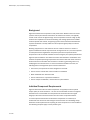
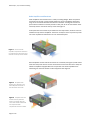
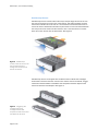
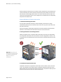
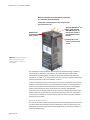
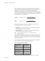
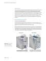
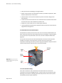
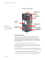
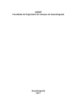
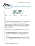
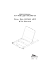
A/V Installation Cooling
A Description of the Effects of Thermal Dynamics
in Cooling Rack Enclosures
Summary
This paper is a practical guide to thermal and fluid dynamics
of audiovisual equipment installations in rack enclosures. A discussion
of the cooling mechanisms used in various A/V components and resultant
airflow is followed by configuration examples of passive convection and
forced air rack enclosures.
Best practices are illustrated along with common pitfalls when designing
rack configurations.
White Paper | A/V Installation Cooling
Background
High-end entertainment components rarely travel alone. Modern movie and music
systems now require network connections via switches and routers, and typically
contain some amount of digital storage. These components connect to high quality
receivers and amplifiers for immersive listening and viewing experiences. Satellite
receivers provide live content, and gaming systems have interactive entertainment.
A power conditioner is usually added to ensure optimal signal quality from all the
components.
Stacking equipment in a rack enclosure set into a wall or stored in a closet is a
popular installation method. Proper thermal management of an A/V rack is important
to avoid performance degradation and prevent premature component failure.
Components must be climate controlled to ensure longevity and optimal performance.
High-end A/V installations must balance function with aesthetics. Installations must
maintain acceptable operating temperatures around the clock and under maximum
loads but should not interfere with the owner’s comfort by generating noise or by
modifying the local environment. To ensure consistent installation success, the
following thermal management topics must be understood.
•
•
•
•
•
How each A/V component has been designed to cool itself
How to use the natural flow of hot air within an installation
When additional fans should be used
How to select fans for a particular installation
How to verify the installation, and monitor for system failures
Individual Component Requirements
High-end electronic audio and video components are typically tuned for optimal
output quality in one environment — the one most comfortable for the test engineer.
Deviation from a comfortable room temperature environment alters the signal
integrity of the audio and video streams and can reduce component lifetime.
To create optimal environments for electronic components it is necessary to
understand how common chassis designs cool themselves. This knowledge helps
determine the best placement and spacing for each component in a rack installation.
The following examples apply to most product types.
2 of 24
White Paper | A/V Installation Cooling
Satellite and Cable Tuners
Most video tuners have large vent arrays on the top of the chassis with very few
bottom vents. This vent design allows cold air to drop into the chassis from the top
and rise out above hot electronics. See Figure 1. This is especially true for standard
definition devices but might not apply to high definition devices.
It is good practice to keep at least one rack unit of clearance above these
components to allow fresh air to enter this airspace and give hot air an easy exit path.
Figure 1 Satellite and cable
receivers typically exhaust hot
air through vents located on
top of the chassis
DVR and Blu-ray Players
Video recorder and high definition playback devices tend to use one or two fans
located at the rear of the chassis to clear hot air from the inner cavity. Air enters the
chassis from the bottom or sides and exhausts straight out the rear. The exhaust fan
is usually visible on the back panel. See Figure 2.
Before installing these players, the location of intake vents must be noted and kept
free from obstructions.
Figure 2 DVR and Blu-ray
players typically intake cool air
from the bottom and sides and
exhaust hot air through vents
located on the back of the
chassis
Page 3 of 24
White Paper | A/V Installation Cooling
Audio Amplifiers and Receivers
Audio amplifiers and receivers have a variety of cooling designs. Most use passive
convection and contain a large vertical heatsink to cool hot amplifying electronics.
Large vents are located beneath and above this heatsink. Leaving one rack unit of
space above and below a receiver provides a clear path for air to enter bottom vents
and easily exit the area above the top vents. See Figure 3.
If adequate clearance cannot be provided for these components, small fan units are
available to help exhaust amplifiers. These fans usually sit on the top vents to pull air
out of the amplifier and redirect the air to an unblocked space.
Figure 3 Common audio
amplifiers use passive convection
to intake air from the bottom and
exhaust out the top of the chassis
Some amplifiers use the sides of the chassis as a heatsink (see Figure 4) while others
have fans that pull air in from the rear and exhaust out the front. Be sure to verify the
airflow of amplifiers equipped with fans and prevent rear intake amplifiers from
exhausting into the front intakes of other equipment. See Figure 5.
Figure 4 Amplifiers with
chassis as a heat sink must
have adequate clearance in
the side areas of the rack
Figure 5 Amplifiers with rear
intakes must be placed so
there is no conflict with the
rack’s bulk airflow and should
not be placed below
components with front intakes
Page 4 of 24
White Paper | A/V Installation Cooling
Gaming Consoles
Gaming consoles have strong internal fans for cooling. Most gaming consoles pull air
from the front, sides and sometimes from the bottom. Air is almost always exhausted
out the rear of the chassis. Air surrounding the chassis must be cool and all vents
must have adequate clearance. See Figure 6.
Figure 6 Gaming consoles
typically intake cool air from
many surfaces and exhaust hot
air through vents located on the
back of the chassis
Network Switches
Network switches have a variety of cooling designs. Small switches typically have side
vents for passive convection while large switches have fans that pull air in one side of
the chassis and exhaust out the other side. Other switches pull air in from the rear
and exhaust out the front, or vice versa. Be sure to power on the switch to verify the
airflow before installation. See Figure 7.
Figure 7 Network switches
have various cooling designs
that must be determined before
installation
Page 5 of 24
White Paper | A/V Installation Cooling
Kaleidescape Servers
Kaleidescape servers contain internal fan arrays that pull large volumes of air from
the front and exhaust air out the rear of the chassis. This design supplies the hard
drives with a reliable stream of cool air. It is essential that the front intake vents on
servers be clear of obstructions. Servers require at least 1 inch of clearance between
the front panel on the server and the rack door, with a rear clearance of 2 inches.
Rear vents must also be clear of obstructions. See Figure 8.
Figure 8 Kaleidescape
servers intake cool air from the
front and exhaust hot air
through vents located on the
back of the chassis
Kaleidescape servers are shipped with slot fillers known as blank disk cartridges
when fewer hard drives than the maximum are ordered. If there are blanks, stagger
hard drives between blanks to distribute heat dissipation between adjacent hard
drives and increase drive lifespan. See Figure 9.
Figure 9 Staggering disk
cartridges with blank
cartridges reduces disk
temperatures and can increase
the lifespan of the drives
Page 6 of 24
White Paper | A/V Installation Cooling
Kaleidescape servers have high airflow. In dusty environments or environments with
pets, the front intake vents can become clogged. It is important to examine the front
vents every 4 months for blockages. Blockages can result in high hard drive
temperatures and premature failures.
Kaleidescape Players
Kaleidescape players contain quiet temperature-controlled fans to cool the
electronics. Air enters players from the front and is exhausted out the rear. Players
move much less air than servers but also require 1 inch of clearance in the front and
2 inches at the rear. Blockages to airflow or high temperature air entering the intake
vents can cause the internal fans to work harder and make more noise. See
Figure 10.
Figure 10 Kaleidescape
players intake cool air from the
front and exhaust hot air
through vents located on the
back of the chassis
Kaleidescape mini players are designed for flexible installations. Mini players can be
rack mounted, wall mounted, or mounted behind the back of the display itself. Cool
air is drawn through the front panel and frontmost bottom vents. Several exhaust
vents are located on the rear panel, both sides, and at the back of the bottom
surface. See Figure 11.
When installing mini players on walls or behind display panels, orienting the front
panel to face down provides the best cooling since natural convection is assisting the
internal fans in this orientation.
Figure 11 Kaleidescape mini
players intake cool air from the
front face and exhaust hot air
through vents located on the
back and sides of the chassis
Page 7 of 24
White Paper | A/V Installation Cooling
Kaleidescape Mini Systems
The Kaleidescape Mini System contains hard drives and high power electronics. The
Mini System has a quiet, temperature-controlled fan array to cool the hard drives and
electronics. Intake vents are located at the front and bottom of the chassis. Exhaust
vents are located at the rear and right side of the chassis. See Figure 12.
Figure 12 Kaleidescape Mini
Systems intake cool air from the
front and bottom, and exhaust
hot air through vents located on
the back and right side of the
chassis
The Mini System ships with a rack mount kit that provides air ducts to pull cool air in
the front. See Figure 13.
Figure 13 Kaleidescape Mini
Systems rack mount kit provides
air ducts to pull air in
Page 8 of 24
White Paper | A/V Installation Cooling
Successful Rack-Mounting Configurations
There are two common, successful A/V rack cooling methods.
•
•
Passive convection
Forced air
Both designs remove heat from the rack by moving air through the rack. The more air
that moves through the rack, the closer the internal rack temperature is to the
temperature of the air pulled into the rack. This section describes how to cool the rack
using each method and how to avoid mistakes that can cause racks to become too
hot.
Passive convection designs are usually preferred when possible because this cooling
method does not require fans. Passive convection designs are less expensive, silent,
and do not rely on components that can degrade and fail over time.
Forced air designs provide cooler rack temperatures and can handle more heat.
These designs are typically used for dense or hidden installations.
Passive Convection Rack Design
Passive convection rack designs are reliable, cost effective and silent but they have
limited heat capacity and require lots of open space both inside and outside the rack.
This cooling design relies on the difference in density between cool air and warm air
to create airflow through the rack. Hot air is less dense and rises above colder air.
Components typically run hotter in a passive convection rack compared to a forced air
rack because the air in the rack must be sufficiently hot before it will rise out of the
rack.
A passive convection rack operates like a chimney. The intake vents are located at
the bottom and the exhaust vents at the top. The hottest components, for example,
the amplifiers, are like the fire at the base of the chimney and are placed in the
bottom rack shelves to create a strong upward draft. Bottom placement also provides
the hot components with the coolest air. If possible, wide, deep racks are
recommended for passive convection designs to reduce drag on the upwardly
rising air.
Well-designed Passive Convection Installation
Components in the top shelves are heated by hot air from the lower components. It is
important to measure the air temperatures surrounding components in the upper
portion of the rack. Components with small internal fans and front intakes, such as
Kaleidescape players, can be placed in the upper shelves as long as the disc trays are
accessible. These players are less affected by higher temperatures inside a rack
because these players pull in cool air from the front of the rack instead of from inside
the rack.
Vent plates are perforated panels screwed onto the front of a rack that allow air to
move in or out of the rack. Vent plates can provide power hungry or hot components
Page 9 of 24
White Paper | A/V Installation Cooling
with a fresh supply of cool air but too many vent plates can degrade the chimney
effect and placing vent plates near components with internal fans can cause air
recirculation (see Figure 15). Vent plates between components in the upper shelves
can provide cool air to those components if necessary but should not be placed in the
middle of the rack or the chimney action will be degraded.
When placing vent plates, use the following guidelines:
•
•
•
Place vent plates at the top and bottom areas of the rack.
Avoid placing vent plates directly above or below equipment with front intakes.
Be sure components without internal fans have adequate vent clearances. Use
blanking plates (not vent plates) in the middle of the rack to provide space above
and below the components.
A well-designed passive convection rack puts ample spacing between components
that do not contain internal fans, and vent plates are kept to the lower region of the
rack. See Figure 14.
Amplifier
Figure 14 Example of a welldesigned rack with passive
convection cooling provides
ample space above and below
components
In the example, the amplifier has a vent directly below it and plenty of space above to
allow cool air to rise through the chassis. The ample spacing between components
gives the slow moving hot air streams exiting each component a chance to mix with
colder air pulled in from the bottom, therefore preventing trapped hot air and the
creation of hot spots. The Kaleidescape 3U Server and players are located in the top
Page 10 of 24
White Paper | A/V Installation Cooling
shelves where the internal rack air is hottest. These components can be stacked and
are less affected by the hotter internal air because they draw reliably cool air in from
the front of the rack through internal fans. The rack is wide with plenty of open vent
area at the top and bottom of the rack, and placed in a shaded area of an adequately
temperature controlled room.
Common Mistakes for Passive Convection
1. Obstructions Choking the Airflow
For the passive convection chimney to work effectively, there must be a large
unobstructed pathway from the bottom of the rack to the top, both in the rear and at
the sides of the rack.
Common examples of obstructions include rear-mounted components like network
switches or rack shelves that extend all the way to the back of the rack.
2. Placing Vent Panels in the Wrong Position
Placing vent plates near a component with internal fans can create air recirculation.
This component will breathe in its own exhaust as well as degrade the chimney. This
is especially true for Kaleidescape servers because of the powerful internal fans. See
Figure 15.
Stacking
without
vent spacing
Figure 15 Intake vents near
components with internal fans
in a passive convection rack
design can cause air
recirculation
Blanking
plate no
vents
3. Insufficient Component Clearance
Insufficient clearance for top/bottom vented units does not allow cool air in and hot
air out. This situation occurs when there is insufficient clearance above exhaust or
below intake vents for components without internal fans. Components with top vents
should have at least one rack unit of space above them.
Page 11 of 24
White Paper | A/V Installation Cooling
4. Compound Heating
This problem occurs when hot exhaust air from a lower component flows directly into
the intake vents of the component above, for example, when two amplifiers are
stacked on top of each other. The bottom amplifier exhausts hot air out the top
directly into the bottom intake vents of the upper amplifier. The upper amplifier then
operates much hotter than the lower amplifier.
Place the upper amplifier on a rack shelf with full bottom plate (no vents) to prevent
compound heating. See Figure 16.
127°F (53°C) exhaust air
Figure 16 Compound heating
occurs when hot exhaust air from
a lower component flows directly
into the intake vents of the
component above
Amplifier B
Unit B operates 27°F (15°C)
hotter
Amplifier A
100°F (38°C) exhaust air
directed into intake of
Amplifier B
73°F (23°C) intake air
5. Improper Room or Closet Cooling
With a passively-cooled rack, the room or closet temperature must be much cooler
than the internal rack temperature to keep air moving inside the rack. If the room is
not properly cooled, temperatures both in the rack and in the room will continue to
rise, potentially over the course of hours or days after the installation is complete.
Windows and sun exposure also affect rack temperature. Be sure to factor heating
from the sun when calculating whether the cooling system for the room is sufficient.
Sunlight can also heat the rack enclosure significantly, especially if shining on a large
portion of the rack, through a transparent front door, or on the back of the rack.
6. Too Much Heat
If the heat output from the housed electronics exceeds 1,700 BTU/hr (500 W), a
passive convection design is not sufficient. Rack manufacturers specify the best ways
to set up their racks for passive convection and how much heat their racks can
handle. If the passive rack air temperature is measuring above 95°F (35°C) at the
top vents, fans must be added to implement a forced air rack design.
Page 12 of 24
White Paper | A/V Installation Cooling
Note:
Multiply the inefficiency (100% - efficiency in %) of an amplifier by the total
rated power to determine the amplifier’s heat output.
Forced Air Rack Design
A forced air rack design uses fans or blowers to remove heat by creating pressure
differences that ensure a steady flow of air through the rack enclosure. This design is
typically used for dense rack installations where considerable heat is generated
inside the rack or where space constraints cannot support passive convection.
Forced air can maintain cooler temperatures for electronic components because of
the increased amount of air flowing through the rack.
The installation designer has greater aesthetic control when using forced convection
because the vertical placement of specific components has little effect on the overall
cooling performance unless a component is blocking the main airflow path of an
intake vent or the rack’s exhaust fans.
When designing a forced air rack, the most important design features are 1) the
placement of vent plates, and 2) the type and size of exhaust fans. Vent plates are
perforated metal plates attached to the front of the rack. Vent plates allow air to flow
into the rack from the environment. They come in various “open area” designs, the
more open area, the easier for the air to travel in. Vent plates with the most open area
are typically added at the bottom of the rack. Those with lesser open area are usually
placed in the middle to prevent the bulk of the airflow from entering the middle of the
rack and skipping the lower electronics.
When placing vent plates, use the following guidelines.
•
The total open area of all vent plates should be equal, at minimum, to the
combined intake area of all exhaust fans.
•
Vent plates should not be placed in the upper region of the rack, otherwise the
bulk of the airflow will skip the electronic components in lower shelves.
•
Blanking plates can be used to provide clearance for electronics vented at the top.
Well-designed Forced Air Installation
Figure 17 shows correct placement of various electronic components in a forced air
rack design.
Page 13 of 24
White Paper | A/V Installation Cooling
Waste heat fluctuates from 2,000 BTU/hr (600 W) (idle)
to 7,000 BTU/hr (2000 W) (full load)
Temperature controlled fans keep the rack quiet when
the electronics are idle
Blanking plate
to give fan intake
plenty of space
Three 200 CFM (340 m3/hr)
fans in parallel produce
600 CFM (1,000 m3/hr)
total air flow, capable of
cooling amplifiers under
full load
Blocking strip for side
vents to prevent short air
circuits
Figure 17 Example installation
with proper vent placement
and fan sizing in a forced air
rack design
The example has more equipment than the passive convection design, producing
approximately 2,000 watts (7,000 BTU/hr) of waste heat with two fully loaded
multichannel amplifiers. Airflow calculations determine that 600 CFM (cubic feet
per minute) or 1,000 m3/hr (cubic meters per hour) of airflow is required to keep the
internal temperature of the rack below 85°F (30°C).
To prevent large fan losses caused by drag, the rack must maintain at least 2 inches
between the rear door and the rear of any component. Cables must be organized to
prevent any obstruction in the vertical flow of air in the sides of the rack. Blanking
plates maintain clearance above components with top vents. Kaleidescape
components are stacked to conserve space and there is nothing blocking their front
intakes. Note that the top side vents have been blocked to prevent air recirculation
and the top four shelves are vacant to provide the rack exhaust fans with adequate
clearance at fan intakes.
Calculating Rack Airflow
The amount of airflow required for the system must be carefully calculated to ensure
that the internal rack temperature remains below 85°F (30°C) under full load. Too
little airflow can result in high internal rack temperatures, and too much airflow can
be noisy and distracting.
Page 14 of 24
White Paper | A/V Installation Cooling
When calculating airflow, the total heat output produced by all of the electronic
components must be addressed. Each component has heat output information on a
safety sticker or in the user manual. (Note that power dissipated through
loudspeakers is not heat output into the rack. Amplifier heat output is found in the
user manual by multiplying the inefficiency (100% - efficiency in %) of an amplifier by
the total rated power of the amplifier.) The formula below can be used to determine
the required airflow for a rack installation.
Imperial
Airflow in CFM = 0.94 ×
Heat Output in BTU/hr
85°F - Room Temperature in °F
Metric
Airflow in m3/hr = 3.00 ×
Heat Output in W
30°C - Room Temperature in °C
For example, if heat output is 7,000 BTU/hr and the room temperature is 73°F,
the required airflow is 0.94 × (7000/12) = 550 CFM.
•
Heat Output: The sum of all heat released by the electronic equipment into the
internal airspace of the rack when at full load.
•
Room Temperature: The air temperature of the air entering the rack system
(measured directly in front of the intake vent plates).
Note:
CFM = cubic feet per minute; m3/hr = cubic meters per hour;
BTU/hr = watts x 3.4
Higher altitudes require greater airflow because of the reduced air density. Heat is
removed from the rack by air molecules. Less heat is removed from the rack when
there are fewer air molecules (lower density air). See Table 1 for airflow adjustment
factors for given altitudes.
Find the installation altitude, then multiply the calculated airflow by the adjustment
factor to determine the required airflow at higher altitudes.
Table 1 Airflow Adjust Factors for Altitude
Installation Altitude
Adjustment Factor
Sea Level
1.00
2,000 ft (600 m)
1.05
4,000 ft (1,200 m)
1.15
6,000 ft (1,800 m)
1.25
8,000 ft (2,400 m)
1.35
10,000 ft (3,000 m)
1.45
For example, at 8,000 ft, the adjusted airflow is 550 CFM × 1.35 = 740 CFM.
Page 15 of 24
White Paper | A/V Installation Cooling
Selecting Fans
Once the required rack airflow has been calculated, the correct fans must be chosen.
Fans always operate below the manufacturer’s specified airflow numbers when
installed. Published airflow numbers are “free air” flow, this means that the fan is
floating in free space without any obstructing objects nearby. When placed in a rack
system, the fan will have to fight the drag created when air moves through vents or
small channels, or changes flow direction, or suddenly contracts or expands. It is good
practice to add an additional 15% to the rack airflow calculation to account for
performance losses attributed to drag and gradual degradation due to aging of fan
bearings.
Common Mistakes of Forced Air
1. Fans in Series Do Not Add Up
When two fans are “in series” the first fan intakes air from the surroundings and
blows air into the rack while the second exhausts air out of the rack. Fans in series do
NOT produce double the airflow unless system drag is large.
A fan moving 50 CFM of air located at the intake area of a rack and a 50 CFM fan at
the rack exhaust can only move a maximum of 50 CFM through the rack. When fans
are placed in series, the sensitivity to obstructions is reduced but the total airflow is
not increased. To achieve 100 CFM, two 50 CFM fans have to be placed side by side,
or “in parallel” as far apart as possible. See Figure 18.
Fans in series
Fans in parallel
Fan B
50 CFM
50 CFM
Fan C
50 CFM
Fan D
50 CFM
100 CFM
Figure 18 Fans in series do
NOT produce double the
airflow; fans in parallel
combine airflow production
Fan A
50 CFM
Fan A and Fan B are in series with a
maximum system airflow of 50 CFM
Page 16 of 24
Fan C and Fan D are in parallel with a
maximum system airflow of 100 CFM
White Paper | A/V Installation Cooling
2. Improper Use of Fans in Parallel
Fans in parallel must be of equal power or airflow rating. A weak fan with low airflow
located next to a strong fan with high airflow will result in air recirculation through the
weak fan. The strong fan pulls air through the weak fan, reversing the airflow of the
weak fan and undermining the intended airflow of the rack installation.
Fans in parallel must also be placed on the same temperature control circuit to
prevent one fan from operating at higher speeds than the other.
Lastly, when fans are placed in parallel a fan failure drastically reduces the overall
rack airflow because the failed fan acts as an inlet. Airflow enters the failed fan and
skips the electronics in this situation. See Figure 19.
Working fan
Failed or a weaker fan
Turbulent
recirculation
air in rear
of components
Figure 19 Air can be
recirculated by using unequal
fans in parallel with unequal
ratings
3. Obstructing Fan Inlets
Fans operate far below published airflow if objects are placed near their intake areas.
In addition, fan noise increases substantially when objects are placed in front of the
intake because of the air turbulence created. See Figure 20. It is good practice to
keep objects at least one fan diameter away from the fan intake area.
d
d
Figure 20 Obstructed fan inlets
degrade fan output
Page 17 of 24
The Kaleidescape players are too close
to the fan inlet and should be located
lower in the rack, at least one fan diameter
away from the inlet.
Airflow is reduced and noise is
increased when blockages are
within a fan diameter of the intake.
White Paper | A/V Installation Cooling
4. Misguided Airflow
Rack enclosures might require modification by the installer for forced air designs
because racks are often shipped in a passive convection configuration. All vents in
the upper portion of the rack must be blocked for forced air designs when the exhaust
fan is located at the top.
Upper vents are typically located on the side walls or rear door. A top mounted
exhaust fan pulls most of the airflow through these vents and bypasses the
electronics components. The same is true for oversized vent panels located in the top
or middle of the rack. See Figure 21.
Good design practice is to seal the entire rack, and then add vent panels or remove
seals where air intakes should be located. There must be a solid door at the rear of
the rack.
Unblocked top vents
undermine forced
convection airflow
Top vent
Top vent
Figure 21 Top vent air is shortcircuited if vents are not blocked
5. Weak Fans or Constricted Airflow
If an electronics cabinet is extremely dense, has obstacles that create many turns in
the end-to-end airflow path, or the required rack airflow exceeds 500 CFM, the 15%
compensation for performance losses caused by drag might not be high enough. A
radial fan or blower might be a better option than typical axial fans designed for A/V
rack systems. Radial fans are more powerful and better able to overcome drag but
rarely appear attractive on paper with a free air flow of approximately half an axial fan.
A radial fan can have half the free air flow of a similar sized axial fan but double the insystem flow if the system drag is significant.
If the system has been installed and the airflow is not sufficient, use the following
points to troubleshoot the rack airflow.
Page 18 of 24
White Paper | A/V Installation Cooling
•
•
Verify that all fans are blowing in the right direction.
•
Confirm that the rack top vents intended for passive convection designs have
been blocked.
•
Increase the size of the intake vents. The combined area of all intake vents should
be at least the size of the combined fan intake areas.
•
•
Replace fans with models that can handle higher pressures.
Search for and remove any constrictions caused by oversized components, cable
bundles, blocked vents or rack doors.
Try using radial fans (blowers) with equivalent airflow or add fans in series with the
original fans. See Figure 18.
6. Choked Airflow in the Frontal Airspace
Components that extend past the front of the rack can constrict airflow between the
front of the rack and any front door. When front doors are installed, it is good practice
to have vents at the top and bottom of the door, and in the middle if feasible. See
Figure 22.
The total vent area for the front door should equal the total area of all vent plates
installed on the front of the rack plus the total vent area of all front intake
components. Recessing rack rails to provide a large space between component fronts
and the inside surface of the front door is also recommended.
Upper
inlet
2 inches
(5 cm)
1 inch
(2.5 cm)
Figure 22 Proper clearances
must be maintained to prevent
choked airflow
Lower
inlet
7. Lack of Periodic Cleaning
If the rack is located in a dirty environment, the intake vents for the rack and
components can become clogged with dust. The wire chases can also become dirty.
Educating home owners on cleaning procedures helps ensure that the rack system
consistently operates at peak efficiency.
Page 19 of 24
White Paper | A/V Installation Cooling
Temperature Monitoring and Design Verification
Design Verification
The final installation step is to perform a thermal design verification under the
following conditions:
•
The rack must be installed in its final location. (Testing in the shop before
installation is error prone.)
•
All electronics must be active and fully loaded and in the state that produces the
highest heat output for at least 2 hours.
•
All rack doors must be closed and fans must be running from the intended control
circuit if present.
Air temperatures must be tested at rack intake and exhaust vents at a minimum.
Temperatures of each component intake must also be measured if possible. Simple
mercury thermometers or basic digital temperature sensors with 2 degree accuracy
can be used. Air temperature probes should not touch any component surface.
Figure 23 shows typical test points.
1) Air exiting the enclosure — The recommended temperature of air exiting the
enclosure is 85°F (30°C) or lower.
2) Air entering the enclosure — Verify that the intake air is at the expected room
temperature, around 73°F (23°C) or lower.
3) Air at intake vents for each component — Hot spots can form in areas where air is
trapped inside the rack; so it is important to measure the air intake temperatures at
each component. Be sure these air temperatures are below the maximum ratings for
the components.
Page 20 of 24
White Paper | A/V Installation Cooling
Test Points for Design Verification
Exhaust temperature
(inside rack)
Top component
intake temperature
Front intake
temperature
High power component
intake temperature
Figure 23 Temperature
measurement locations
include air intake and exhaust
points as well as component
intake vents
Secondary rack intake
temperature
Rack intake temperature;
verify temperature
is at the designed
room temperature
Temperature Monitoring
Because environmental and physical changes in a household affect electronic
installations, in-system thermal monitoring and alerting is recommended. A
monitoring system can alert the system administrator of rack and HVAC failures, as
well as overheating caused by pet fur clogging air intake vents, a new thermostat
setting, or some other circumstance. A monitoring system can substantially reduce
the cost of such failures.
Two classes of monitoring systems are available, local and remote.
Local systems are typically integrated into a fan control circuit that can kill power to
the rack electronics if the internal air temperature rises to a damaging level (113°F or
45°C is a typical trip point).
Remote systems can provide real time and historical temperature data to both owner
and dealer via the Internet. These systems can also provide the following advantages.
•
•
Page 21 of 24
Generate email alerts if temperatures elevate to a warning condition.
Enable proactive action because the dealer can perform periodic checks to verify
that the rack is operating in a stable manner consistent with design goals.
White Paper | A/V Installation Cooling
•
Reduce system downtime because the dealer is automatically alerted if a
suspicious situation occurs. Diagnostic services such as component temperature
history can speed debugging thermal problems.
Kaleidescape Alerts are an example of a remote monitoring system included with A/V
equipment. This service provides current and historical temperatures of each
component in the system via the Kaleidescape Extranet. The system administrator is
alerted of elevated temperatures through email. Monitoring systems built into rack
components are cost-effective and can be used to monitor the temperatures of
surrounding environments indirectly which helps protect other equipment as well.
Conclusion
A successful rack installation requires knowledge of the equipment installed, some
planning, and thorough verification. The cooling design of each component and
proper vent clearances must be considered. Airflow calculations determine the
necessary fan configuration, eliminating guesswork and time consuming
experimentation. Design verification ensures the exhaust temperature is within
acceptable range and that there are no unexpected hot spots inside the rack.
Two simple and successful rack cooling designs are passive convection and forced
air. Passive convection is silent and does not rely on fan components that can fail
over time. Forced air rack designs rely on air movers such as fans or blowers. Forced
air rack designs are required for racks in tight spaces or with high heat output.
Regardless of the rack design, thermal monitoring equipment can help prevent
cooling system failures resulting in damaged equipment. Local and remote
monitoring systems are often complementary. Some A/V equipment offers built-in
remote temperature monitoring that allows dealers to check the environment of the
installation indirectly. These systems allow dealers to offer proactive assistance to the
clients and additional thermal protection.
Rack installation is one of the last steps in the transaction between customer and
dealer. The installation is the final impression. Successful thermal installations
improve the relationship between customer and dealer by maintaining a pleasant
living environment and improving the lifetime of the owner’s equipment.
Page 22 of 24
White Paper | A/V Installation Cooling
References
Çengel, Yunus A.. 1997. Introduction to Thermodynamics and Heat Transfer.
New York: Irwin/McGraw-Hill.
Ebm-papst. Compact Fans for AC and DC, Catalogue 2008. St. Georgen: ebm-papst.
Kordyban, Tony. 1998. Hot Air Rises and Heat Sinks: Everything You Know about Cooling
Electronics. New York: The American Society of Mechanical Engineers.
Mälhammar, Åke. Natural Convection and Chimneys.
http://www.frigprim.com/articels2/parallel_plchim.html (accessed June 4, 2010).
Mälhammar, Åke. Convection and Air Properties, Altitude Impact.
http://www.frigprim.com/articels3/Airprop2.html (accessed June 4, 2010).
Roknaldin, Farzam. 2008. Practical Electronics Cooling Analysis, Modeling and Measurement.
Santa Clara: Applied Thermal Technologies.
Schluter, Bob. 2002. Controlling the Temperature Inside Equipment Racks.
http://middleatlantic.com/pdf/ThermalManagement.pdf (accessed June 4, 2010).
Schluter, Bob. 2008. Thermal Management: the HOT topic.
http://www.connectedhometechnology.com/article/thermal-management-hot-topic
(accessed June 4, 2010).
Sergent, Jerry E. & Al Krum. 1998. Thermal Management Handbook: for Electronic Assemblies.
New York: McGraw-Hill.
White, Frank M. 2003. Fluid Mechanics fifth edition. New York: McGraw-Hill Higher Education.
Page 23 of 24
This document is for informational purposes only. Kaleidescape makes no representations or warranties, express or implied,
regarding the accuracy or completeness of the information contained herein and Kaleidescape shall have no obligation to provide
updates to this information in the future. Copyright © 2010 Kaleidescape, Inc. All rights reserved. Kaleidescape and the
Kaleidescape logo are trademarks of Kaleidescape, Inc. and are registered in the United States and certain other jurisdictions.
Other trademarks and trade names are owned by third parties and may be registered in some jurisdictions.
Kaleidescape Part No. 111-0014-00 Rev 1.