1
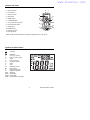
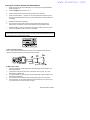
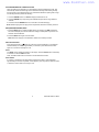
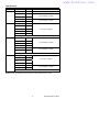
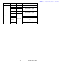
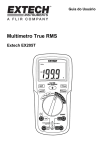
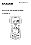
www.burntec.com User's Guide Multimeter with IR Thermometer Extech EX210 www.burntec.com Introduction Congratulations on your purchase of the Extech EX210 Autoranging Multimeter. This meter measures AC/DC Voltage, AC/DC Current, Resistance, Diode Test, and Continuity plus noncontact InfraRed Temperature. Proper use and care of this meter will provide many years of reliable service. Safety This symbol adjacent to another symbol, terminal or operating device indicates that the operator must refer to an explanation in the Operating Instructions to avoid personal injury or damage to the meter. WARNING This WARNING symbol indicates a potentially hazardous situation, which if not avoided, could result in death or serious injury. CAUTION This CAUTION symbol indicates a potentially hazardous situation, which if not avoided, may result damage to the product. MAX 600V This symbol advises the user that the terminal(s) so marked must not be connected to a circuit point at which the voltage with respect to earth ground exceeds (in this case) 600 VAC or VDC. This symbol adjacent to one or more terminals identifies them as being associated with ranges that may, in normal use, be subjected to particularly hazardous voltages. For maximum safety, the meter and its test leads should not be handled when these terminals are energized. This symbol indicates that a device is protected throughout by double insulation or reinforced insulation. PER IEC1010 OVERVOLTAGE INSTALLATION CATEGORY OVERVOLTAGE CATEGORY I Equipment of OVERVOLTAGE CATEGORY I is equipment for connection to circuits in which measures are taken to limit the transient overvoltages to an appropriate low level. Note – Examples include protected electronic circuits. OVERVOLTAGE CATEGORY II Equipment of OVERVOLTAGE CATEGORY II is energy-consuming equipment to be supplied from the fixed installation. Note – Examples include household, office, and laboratory appliances. OVERVOLTAGE CATEGORY III Equipment of OVERVOLTAGE CATEGORY III is equipment in fixed installations. Note – Examples include switches in the fixed installation and some equipment for industrial use with permanent connection to the fixed installation. OVERVOLTAGE CATEGORY IV Equipment of OVERVOLTAGE CATEGORY IV is for use at the origin of the installation. Note – Examples include electricity meters and primary over-current protection equipment 2 EX210-EU-EN-V2.1-08/10 www.burntec.com CAUTIONS • Improper use of this meter can cause damage, shock, injury or death. Read and understand this user manual before operating the meter. • Always remove the test leads before replacing the battery or fuses. • Inspect the condition of the test leads and the meter itself for any damage before operating the meter. • Use great care when making measurements if the voltages are greater than 25 VAC rms or 35 VDC. These voltages are considered a shock hazard. • Warning! This is a Class A device. This device can cause interference in residential areas. • Always discharge capacitors and remove power from the device under test before performing Diode, Resistance or Continuity tests. • Voltage checks on electrical outlets can be difficult and misleading because of the uncertainty of connection to the recessed electrical contacts. Other means should be used to ensure that the terminals are not "live". • If the equipment is used in a manner not specified by the manufacturer, the protection provided by the equipment may be impaired. • This device must not be used by children. It contains hazardous objects as well as small parts that the children could swallow. • Do not leave batteries and packing material lying around unattended; they can be dangerous to children. • In the event that this device will be stored for an extended period of time, remove the batteries. • Expired or damaged batteries can be hazardous to skin. Use suitable hand gloves in such cases. • Do not short-circuit the battery. Do not place the battery near a fire. 3 EX210-EU-EN-V2.1-08/10 www.burntec.com SAFETY INSTRUCTIONS This meter has been designed for safe use, but must be operated with caution. The rules listed below must be carefully followed for safe operation. 1. NEVER apply voltage or current to the meter that exceeds the specified maximum: Input Protection Limits Function Maximum Input V AC/DC, Resistance, Diode Test, Continuity 600 VDC/AC rms μA or mA AC/DC 200mA fused A AC/DC 10A fused 2. USE EXTREME CAUTION when working with high voltages. 3. DO NOT measure voltage if the voltage on the "COM" input jack exceeds 600V above earth ground. 4. NEVER connect the meter leads across a voltage source while the function switch is in the current, resistance, or diode mode. Doing so can damage the meter. 5. ALWAYS discharge filter capacitors in power supplies and disconnect the power when making resistance or diode tests. 6. ALWAYS turn off the power and disconnect the test leads before opening the covers to replace the fuse or batteries. 7. NEVER operate the meter unless the back cover and the battery and fuse covers are in place and fastened securely. 8. If the equipment is used in a manner not specified by the manufacturer, the protection provided by the equipment may be impaired. 4 EX210-EU-EN-V2.1-08/10 www.burntec.com Controls and Jacks 1. IR Thermometer 2 2. Laser Pointer 3. 2000 count LCD 3 4. MAX button 8 4 5 5. MODE button 6. FUNCTION switch 7. mA, µA and 10A input jacks 9 10 6 8. IR Thermometer button 9. HOLD button 11 12 7 10. RANGE button 11. Positive input jack 12. COM input jack 1 Note: Tilt stand, test lead holders, and battery compartment are on rear of unit. Symbols and Enunciators Continuity µ m A k M Ω V AC DC ºF ºC MAX AUTO HOLD SCAN Diode test -6 micro (10 ) (amps) -3 milli (10 ) (volts, amps) Amps 3 kilo (10 ) (ohms) 6 mega (10 ) (ohms) Ohms Volts Alternating current Direct current Degrees Fahrenheit Degrees Centigrade Maximum Autoranging Display hold IR temperature in progress 5 EX210-EU-EN-V2.1-08/10 www.burntec.com Operating Instructions WARNING: Risk of electrocution. High-voltage circuits, both AC and DC, are extremely dangerous and should be measured with great care. 1. ALWAYS turn the function switch to the OFF position when the meter is not in use. 2. If “OL” appears in the display during a measurement, the value exceeds the range you have selected. Change to a higher range. AC/DC VOLTAGE MEASUREMENTS CAUTION: Do not measure DC voltages if a motor on the circuit is being switched ON or OFF. Large voltage surges may occur that can damage the meter. 1. Rotate the function switch to the VAC or VDC position. 2. Insert the black test lead banana plug into the negative COM jack. Insert the red test lead banana plug into the positive V jack. 3. Touch the black test probe tip to the negative side of the circuit. Touch the red test probe tip to the positive side of the circuit. 4. Read the voltage in the display. AC/DC CURRENT MEASUREMENTS 1. Insert the black test lead banana plug into the negative COM jack. 2. Press the MODE button to indicate “DC” or “AC” on the display. 3. For current measurements up to 2000µA, set the function switch to the µA position and insert the red test lead banana plug into the µA/mA jack. 4. For current measurements up to 200 mA DC, set the function switch to the mA position and insert the red test lead banana plug into the µA/mA jack. 5. For current measurements up to 10A DC, set the function switch to the 10A position and insert the red test lead banana plug into the 10A jack. 6. Connect the test leads in series with the circuit under test. 7. Apply power to the circuit. 8. Read the current in the display. 6 EX210-EU-EN-V2.1-08/10 www.burntec.com RESISTANCE MEASUREMENTS WARNING: To avoid electric shock, disconnect power to the unit under test and discharge all capacitors before taking any resistance measurements. Remove the batteries and unplug the line cords. 1. Rotate the function switch to the Ω position. 2. Insert the black test lead banana plug into the negative COM jack. Insert the red test lead banana plug into the positive Ω jack. 3. Touch the test probe tips across the device under test. 4. Read the resistance in the display. CONTINUITY CHECK WARNING: To avoid electric shock, never measure continuity on circuits or wires that have a voltage potential. 1. Rotate the function switch to the position. 2. Insert the black lead banana plug into the negative COM jack. Insert the red test lead banana plug into the positive jack. 3. Press the MODE button to indicate“ " on the display 4. Touch the test probe tips to the circuit or wire you wish to check. 5. If the resistance is less than the continuity threshold, the audible signal will sound. DIODE TEST 1. Rotate the function switch to the green position. 2. Insert the black test lead banana plug into the negative COM jack and the red test lead banana plug into the positive jack. 3. Press the MODE button to indicate “ “and “V” on the display. 4. Touch the test probes to the diode under test. Forward voltage will typically indicate 0.400 to 0.700V. Reverse voltage will indicate “OL”. Shorted devices will indicate near 0V and an open device will indicate “OL” in both polarities. 7 EX210-EU-EN-V2.1-08/10 www.burntec.com NON-CONTACT INFRARED TEMPERATURE MEASUREMENTS 1. Rotate the function switch to the IR position. The upper right four digit temperature display will switch on. 2. Press the MODE button to select °F or °C. 3. Aim the infrared sensor (top of meter) at the surface to be measured. 4. Press and Hold the IRT button to turn on the IR thermometer and laser pointer. The laser pointer identifies the surface spot to be measured and “SCAN” will flash in the display. 5. Read the temperature in the display. 6. The area of the surface to be measured must be larger than the spot size as determined by the distance to spot size values listed in the specification table. 7. button to turn the IR thermometer and laser pointer off. “HOLD” Release the IRT and the final measured value will remain in the display. WARNING: Do not directly view or direct the laser pointer at an eye. Low power visible lasers do not normally present a hazard, but may present some potential for hazard if viewed directly for extended periods of time. IR Spot to Distance Diagram The 4:1 spot to distance ratio determines the size of the measured surface area with respect to the distance the meter is held away from the surface. 1” @ 4” 20mm @ 80mm 2” @ 8” 4” @ 16” 40mm @ 160mm 80mm @ 320mm IR Measurement Notes 1. 2. 3. 4. 5. The object under test should be larger than the spot (target) size calculated by the field of view diagram. If the surface of the object under test is covered with frost, oil, grime, etc., clean before taking measurements. If an object's surface is highly reflective, apply masking tape or flat black paint to the surface before measuring. The meter will not make measurements through glass steam, dust, and smoke. To find a hot spot, aim the meter outside the area of interest then scan across (in an up and down motion) until the hot spot is located. 8 EX210-EU-EN-V2.1-08/10 www.burntec.com AUTORANGING/MANUAL RANGE SELECTION When the meter is first switched on, it automatically enters the AutoRanging mode. This automatically selects the best range for the measurements being made and is generally the best mode for most measurements. For measurement situations requiring that a range be manually selected, perform the following: 1. Press the RANGE button. The “AUTO” display indicator will turn off. 2. Press the RANGE key to step through the available ranges until the range desired is selected. 3. Press and hold the RANGE button for 2 seconds to exit manual ranging. Note: Manual ranging does not apply to the Temperature, Diode and Continuity functions. MAX (MAXIMUM READING) MODE 1. Press the MAX button to activate the MAX mode. The display icon "MAX" will appear. The meter will display and hold the maximum reading and will update only when a new maximum value is detected. 2. Press the MAX button again to exit the mode. Note: Max does not apply to the Resistance, Diode and Continuity functions. DISPLAY BACKLIGHT Press and hold the IRT button for 2 second to turn the backlight on. The backlight will automatically turn off after approximately 10 seconds or press and hold the button again for 2 seconds to manually turn it off. HOLD The HOLD function freezes the reading in the display. Press the HOLD button momentarily to activate or to exit the HOLD function. Note: The HOLD button does not function in the IR measurement mode. AUTO SLEEP If no button is pressed the auto sleep feature will place the meter in sleep mode after approximately 15 minutes of operation. If this happens, press any button to wake the meter or switch the meter to OFF if it no longer in use. 9 EX210-EU-EN-V2.1-08/10 www.burntec.com Maintenance WARNING: To avoid electric shock, disconnect the test leads from any source of voltage before removing the back cover or the battery or fuse covers. WARNING: To avoid electric shock, do not operate the meter until the battery and fuse covers are in place and fastened securely. This MultiMeter is designed to provide years of dependable service, if the following care instructions are followed: 1. KEEP THE METER DRY. If it gets wet, wipe it off. 2. USE AND STORE THE METER IN NORMAL TEMPERATURES. Temperature extremes can shorten the life of the electronic parts and distort or melt plastic parts. 3. HANDLE THE METER GENTLY AND CAREFULLY. Dropping it can damage the electronic parts or the case. 4. KEEP THE METER CLEAN. Wipe the case occasionally with a damp cloth. DO NOT use chemicals, cleaning solvents, or detergents. 5. USE ONLY FRESH BATTERIES OF THE RECOMMENDED SIZE AND TYPE. Remove old or weak batteries so they do not leak and damage the unit. 6. IF THE METER IS TO BE STORED FOR A LONG PERIOD OF TIME, the batteries should be removed to prevent damage to the unit. BATTERY and FUSE Replacement WARNING: To avoid electric shock, disconnect the test leads from any source of voltage before removing the battery cover. 1. Turn power off and disconnect the test leads from the meter. 2. Open the rear battery/fuse compartment by removing the Phillips head screw on the lower rear of the meter. . 3. Pull down on the cover to release the latch and then lift it off. 4. Remove the old battery or fuse and install a new one of the correct rating. 5. Place the battery/fuse cover back in place. Secure with the screw. WARNING: To avoid electric shock, do not operate the meter until the battery cover is in place and fastened securely. NOTE: If the meter does not work properly, check the fuses and replace the battery to make sure that they are still good and that they are properly inserted. You, as the end user, are legally bound (EU Battery ordinance) to return all used batteries, disposal in the household garbage is prohibited! You can hand over your used batteries / accumulators at collection points in your community or wherever batteries / accumulators are sold! Disposal: Follow the valid legal stipulations in respect of the disposal of the device at the end of its lifecycle 10 EX210-EU-EN-V2.1-08/10 www.burntec.com Specifications Function Range Resolution DC Voltage 200 mV 0.1 mV 2V 0.001V 20V 0.01V 200V 0.1V 600V 1V 200 mV 0.1 mV 2V 0.001V 20V 0.01V 200V 0.1V 600V 1V AC Voltage Accuracy ±(0.8% reading + 6 digits) ±(0.5% reading + 2 digits) ±(0.8% reading + 2 digits) ±(1.0% rdg + 6 digits) All AC voltage ranges are specified from 5% of range to 100% of range DC Current 200 μA 0.1 μA 2000 μA 1 μA 20 mA 0.01 mA 200 mA 0.1 mA 2.000 0.001 A 10 A 0.01 A ±(1.5% reading + 5 digits) ±(2.5% reading + 5 digits) Note:10A for 30 sec max AC Current 200 μA 0.1 μA 2000 μA 1 μA 20 mA 0.01 mA 200 mA 0.1 mA 2.000 0.001 A 10 A 0.01 A ±(1.5% rdg + 5 digits) ±(3.0% reading + 5 digits) Note: 10A for 30 sec max o o o o NOTE: Accuracy is stated at 18 C to 28 C (65 F to 83 F) and less than 75% RH. 11 EX210-EU-EN-V2.1-08/10 www.burntec.com Function Range Resolution Resistance 200 Ω 0.1 Ω 2 kΩ 0.001 kΩ 20 kΩ 0.01 kΩ 200 kΩ 0.1 kΩ 2 MΩ 0.001 MΩ 20 MΩ 0.01 MΩ Temperature IR Accuracy ±(0.8% reading + 5 digits) ±(0.8% reading + 2 digits) ±(2.5% reading + 8 digits) -20 to 0°C ±4°C 0 to 93°C ±(2.0%rdg or 2°C) 93 to 230 -5 to 32°F 0.1°C/°F ±(3.0%rdg or 3°C) ± 8°F 32 to 200°F ±(2.0%rdg or 4°F) 200 to 446°F ±(3.0%rdg or 6°F) 12 EX210-EU-EN-V2.1-08/10 www.burntec.com Enclosure Diode Test Double molded Test current of 0.9mA maximum, open circuit voltage 2.8V DC typical Continuity Threshold 20 to 50Ω, test current <1.5mA Input Impedance 10MΩ VDC/VAC AC Response Average responding ACV Bandwidth 40Hz to 1000Hz IR Spectral response 6 to 16µm IR Emissivity 0.95 fixed IR distance ratio 4:1 Laser pointer Class 2 laser < 1mW power; Wavelength is 630 to 670nm Display 2,000 count backlit liquid crystal display Overrange indication “OL” is displayed Auto Power Off 15 minutes (approximately) Polarity Automatic (no indication for positive); Minus (-) sign for negative Measurement Rate 2 times per second, nominal Battery One 9 volt (NEDA 1604) battery Fuses mA, µA ranges; 200mA 250V ceramic fast blow A range; 10A 600V ceramic fast blow Operating Temperature -10ºC to 40ºC (14ºF to 122ºF) o o o o Storage Temperature -10 C to 60 C (14 F to 140 F) Operating Humidity Max 80% up to 31ºC (87ºF) decreasing linearly to 50% at 40ºC (104ºF) Storage Humidity <80% Operating Altitude 2000 meters (7000 ft) maximum Weight 260 g (9.17oz) Size 147x76x42 mm (5.8x2.9x1.6”) Safety This meter is intended for origin of installation use and protected, against the users, by double insulation per IEC/EN 61010-1:2001 and IEC/EN 61010-031:2002 to Category III 600V; Pollution Degree 2. Approvals CE Copyright © 2010 Extech Instruments Corporation (a FLIR company) All rights reserved including the right of reproduction in whole or in part in any form. 13 EX210-EU-EN-V2.1-08/10