1
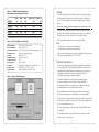
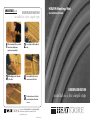
QUICKSTARTguide
HSUFM Heating Mat
UNDERFLOOR HEATING
installed in a few simple steps
1
3
After cleaning the floor, coat the
entire base with primer
(purchased separately).
When happy, secure the mats
to the floor.
2
4
5
Installation Guide
Loosely lay out the lengths of
mat,
Secure and bury the return
connectors into the floor.
UNDERFLOOR HEATING
Position and secure the heat
probe away from other heat
sources.
Telephone: 0117 923 5375 Fax: 0117 923 5374
Victoria Road, Avonmouth, Bristol BS11 9DB
www.heatstore.co.uk
ISSUE 2M 0708
installed in a few simple steps
Contents
IMPORTANT SAFEGUARDS
Do’s & Don’ts
3
Technical data and wiring diagrams
4
Testing
5
Electrical connections
5
Choosing the correct mats
6
Subfloor Preparation
7
Installing mats
9
Covering system
11
Warranty
14
th
Sign off sheet and 17 Edition checklist
15
WHEN USING ANY ELECTRICAL APPLIANCE, BASIC SAFETY
PRECAUTIONS SHOULD ALWAYS BE FOLLOWED.
PLEASE READ ALL INSTRUCTIONS CAREFULLY
AND RETAIN FOR FUTURE REFERENCE
IF IN ANY DOUBT ABOUT THE INSTALLATION OR USE OF THIS
PRODUCT, CONSULT A COMPETENT ELECTRICIAN.
Do’s and Don’ts
Do
l
Thoroughly read this installation guide before starting your project.
l
Use a multi-meter to test the heater/s, before, during and after
covering.
l
Ensure the system is protected by a suitable RCD device (30mA).
l
Ensure that all heating cable and connections are fully encased with
tile adhesive or levelling compound under the floor covering.
l
Install multiple heaters in parallel.
l
Release the cable from the mesh to ensure full coverage in awkward
areas.
l
Ensure that all electrical works conform to Part ‘P’ of the Building
Regulations and current IEE Wiring Regulations.
Don’t
l Cut, shorten, cross or join any part of the heating cables.
2
l
Power up the heaters until the cable has been fully encased and the
wet trade have been allowed to fully dry out.
l
Install the heaters in walls or ceilings under any circumstances.
l
Install the floor sensor close to other heat sources such as radiator
pipes.
l
Spot fix tiles when fixing slabs or large tiles, all floor coverings should
be fully bedded in when fitting.
l
Lay cables closer than 30mm to each other or conductive parts.
l
Install mats if the ambient temperature is below 5ºC.
3
Testing
Figure 1: 160W/m2 Heating Mat wiring
Information and technical specification
COVERAGE
LENGTH
WIDTH
WATTAGE @ 14W/m
1.0m2
1.3m2
2.0m2
4.5m2
7.0m2
9.7m2
2.0m
2.6m
4.0m
9.0m
14.0m
19.4m
0.5m
0.5m
0.5m
0.5m
0.5m
0.5m
160W
200W
320W
720W
1100W
1500W
HSUFM100
HSUFM130
HSUFM200
HSUFM450
HSUFM700
HSUFM970
RESISTANCE ±10%
362Ω
278Ω
183Ω
80Ω
52Ω
37Ω
Figure 2: Technical Data and materials
HEATING ELEMENT:
OUTER INSULATION:
ELECTRICAL INSULATION:
PROTECTIVE LAYER:
VOLTAGE:
MAXIMUM LOADING:
IP RATING OF CABLES:
OUTPUT RANGE:
APPROVALS:
WIRE THICKNESS:
CABLE FLEXIBILITY:
Teflon insulated resistance wires
PVC tested up to 90°C
100% aluminium earth shield and tinned copper screen
Fibreglass mesh above the cable
240V AC - 50Hz
15W per linear metre
IPX7
160W to 1552W
BEAB component approved wire and CE marked
Variable between 2.7mm and 3.2mm
Minimum allowable cable radius 18mm
Figure 3: Typical Circuit Diagram
Test your heating cable with a multimeter before removing the packaging
material to confirm that you have received the product in full working
order. The Ohm rating for each cable should agree to those in Figure 1
above.
AT
THIS POINT, THE CABLE MUST NOT BE CONNECTED TO A POWER SUPPLY TO TEST IT.
The black coldtail is double insulated and carries an earth screen (silver
braid), live and neutral wires. Exposing the ends of these wires will allow
the continuity tests to be carried out with a functional multimeter.
This test should also be done before, during and after tiling.
Tests
• Live to neutral = ohms value as listed opposite.
• Live to earth and neutral to earth = both infinity.
If your tests do not conform to the expected results before, during and after
tiling, please contact Heatstore on 0117 923 5375.
Electrical connections
All work must comply with current IEE wiring regulations and installations
must comply with Part ‘P’ of the Building Regulations. Consult your Local
Authority Building Control Department regarding their requirements for
certification or check with an electrician qualified to issue Part ‘P’
certification regarding your individual installation.
The heater’s coldtail has to be wired into a thermostat with floor
temperature limitation such as Heatstore’s 16Amp HSUFMCN
thermostat/timer. Please see the separate user instructions inside your
thermostat box for the wiring details of the thermostat.
Run the coldtail connection and floor sensor cable in separate plastic
conduit or trunking from your heated floor to the thermostat position.
Up to 2 heaters can be wired straight into the thermostat. A connection box
will be required if installing 3 or more heaters. Ensure that multiple heaters
are wired in parallel, not in series.
The mains power supply must be protected by a suitable RCD (30mA and
up to 4.8kW).
The thermostat should be connected to the power supply via a suitably
rated fused spur or circuit breaker.
4
5
Should the total loading from a combination of heaters exceed the
Amperage rating of the thermostat, the system will require multiple
thermostats or we would recommend the installation of a suitable rated
contactor which would allow the heating system to be run through a single
thermostat for ease of control.
If heating a bathroom or a similar room, the thermostat should be placed
outside of the bathroom on the wall, and the floor should be controlled on
the floor sensor only. The Heatstore HSUFMCN thermostat is IP30 rated.
If the thermostat is placed outside the room to be heated, or inside a
cupboard, the thermostat will have to be reprogrammed (when first
switched on) to only monitor the floor sensor that has been placed into the
heated floor space. If you are unsure how to proceed at any stage of the
installation process, please contact Heatstore on 0117 923 5375.
Choosing the correct combination of mats
When using any suitable floor covering including tiles, carpet, vinyl or
wood. (Please note a levelling compound will be required for use with any
floor covering other than tiles, and for use with mosaic tiles the system
should always be covered with a levelling compound). These systems can
be laid directly onto wooden or insulated concrete bases. They can provide
a complete heating system in well insulated areas and a supplementary
heating system in most other circumstances.
Calculating coverage:
Calculate the total floor area you have in your room (in m2), and then
deduct any areas where underfloor heating can not be laid such as any
floor fixed furniture including baths, shower trays, kitchen units, central
islands etc. This will give you your free floor area.
In normal circumstances we would recommend deducting between 5 and
10% from the your total free floor space that you wish to heat, to give you
the square meters of heating mat that you should install. For areas above
7m2 we would recommend only deducting 5%.
Example: You wish to heat a well insulated lounge that has a well
insulated concrete base and will have ceramic tile covering. You would
take the overall area of 9.5m2 and then deduct any floor fixed units which
in this case take up 1m2. You would then proceed as follows:
From Figure 1 on page 4, the ideal mat combination for this area is one
7.0m2 mat and one 1.0m2 mat.
Although 100% floor coverage is achievable, we recommend leaving a
border of 20mm–50mm around the perimeter of the room as the heating
cables should not touch the walls, kickboards etc.
We would recommend planning your installation out before starting to lay
your heating mats. It is also a good idea to photograph your mat layout
before tiling for future reference.
Sub-floor Preparation
This product can be installed directly onto insulated concrete or old tile
surfaces, wooden floors can be reinforced using 18mm WPB plyboard,
10mm insulation boards or suitable tilebacker boards providing that the
base is fully secured and level.
The sub-floor should all be of the same construction to ensure the system
performs evenly. If the floor construction is not uniform you should use
10mm insulation boards or similar to provide a uniform base.
Heatstore can provide 10mm insulation boards if your sub-floor is not
correctly insulated. The sub-floor should be insulated to current building
regulations and as insulation improves the performance and efficiency of
the system the running cost will be reduced. If there is little or no insulation
within the sub-floor we would recommend using a suitable layer of
insulation. If using insulation boards, the boards should be fixed to
manufacturer’s recommendations (fixed to concrete using flexible tile
adhesive or fixed over wood using galvanised screws with washers).
When the sub-floor is fully secured and level, fitting of the heating system
can commence.
Suitable carpets, vinyl, mosaic tile and floating wooden floor coverings can
be installed above this product, providing that the cables are laid no closer
than 90mm apart when secured and the heaters are then covered with
12mm of flexible levelling compound that we can also supply. The subfloor will also need to be sealed.
9.5m2 – 1m2 = 8.5m2 floor space remaining to heat.
8.5m2 – 5% = 8.07m2 is the coverage of heating mats you required.
6
7
Fig 4: Step 1
Figure 4: Step 1 Apply the primer (purchased separately) evenly
across the whole floor surface that will be heated. This product can prevent
up to 20% heat loss through the subfloor and although less effective than
insulation boards, it does not significantly add to the build height of the
system.
Provide adequate ventilation when applying the primer and avoid walking
over it whilst it is drying (this should take no more than 2 hours).
Suitable carpets, vinyl, mosaic tile and floating wooden floor coverings can
be installed above this product, providing that the cables are laid no closer
than 90mm apart and when secured, the cable is then covered with 12mm
of flexible levelling compound that is available from Heatstore.
Installing the 160w/m2 Heating Mat System
Test each mat with a multi-meter before unpacking to ensure your have
received your product in full working order. See page 5 for testing
instructions. Draw a plan of how you intend to fit your mat(s).
Figure 5: Step 2 Roll out your mat onto your floor. Cut across the
fibre glass mesh when you reach an obstruction, carefully avoiding the
heating cable, you can then rotate the mat through 180° and start laying it
in the opposite direction.
Fig 5: Step 2
In awkward areas the heating cable can be removed from the fibre glass
mesh and laid loosely to ensure the heating system fits your room. When
doing this, try to keep the spacing between the cables similar to that on
your mat to maintain an even output across the floor area and never let
the cables touch or cross. The cables should be secured to the floor with
double sided tape or a hot glue gun.
Figure 6: Step 3 Once in position, remove the backing from the
adhesive tape attached to the underside of your mat/s and secure to your
base. Any loose cable or mesh can be secured by using a hot glue gun or
masking tape. Try to avoid air pockets if taping by pinching the tape tight
around the cable. Multiple heaters are laid in the same way and they do
not join together, they have to be laid in parallel.
The cables should never be less than 30mm apart whether they are on the
heating mat or laid loosely on the floor. If you find that you have to lie the
cable separated from the mat in rows less than 30mm apart to fit your
room, STOP, as the matting is too big for your area. The heating cable can
8
9
Fig 6: Step 3
not be cut to shorten itself without destroying it.
Figure 7: Step 4 The return joint at the end of the heating cable and
the connection between the heating cable and the cold tail have to be kept
straight and must be laid within the floor area beneath your tiles or chosen
floor covering. These will have to be chased into the sub-floor to ensure
they rest at the same height as the top of the heating cable. These must not
be covered with tape, but do have to be fully encased in tile adhesive or a
levelling compound.
Figure 8: Step 5 The floor sensor (contained inside the thermostat
box), should be placed halfway between two runs of the heating element.
The sensor wire must not cross the heating cable and should be placed
approx. 400mm into the heated floor space. The sensor cable can be
extended up to 50m using a twin sheathed high temperature PVC cable
and the connection between the two wires must be waterproof and fully
insulated. The floor sensor should be placed into a length of suitable close
ended conduit (8–12mm diameter) so that it can be easily replaced if
required.
When placing the floor sensor, avoid areas affected by other heat sources,
such as hot water pipes and areas that will be covered with furniture at a
later date.
Multiple heaters can be installed in one room but must be connected in
parallel (they do not join together). Up to 2 cables can be wired into the
back of the thermostat. More than 2 cables will require a connection box.
If your system exceeds the Amperage rating of your thermostat, additional
thermostats can be used or you can install a contactor or similar device to
allow the heating system to operate safely through a single thermostat for
ease of control.
Fig 7: Step 4
Test each heater with a multimeter again before covering and if not
covering right away, protect the heating system by placing cardboard or
carpet on top of it and avoid unnecessary traffic within the area.
Adding flooring over the system
Take care to avoid dropping sharp objects or tiles onto the cable, do not
stack or cut tiles across the cabled area and wear soft soled shoes if you
must walk on it.
10
11
Fig 8: Step 5
push the adhesive along the cable rather than against it. Care should be
exercised to prevent damage to or dislodging of the mats. Ideally, lay
carpet or cardboard on top of the exposed cable and use this as a crawl
board to avoid damaging the system. Although the cable is reinforced, it is
ideal that the trowel does not make contact with the cable itself.
If a tile needs to be moved after placement this must be done carefully to
avoid damaging the heating cable.
Never use the heater to ‘dry out’ the tile adhesive. The system must not be
turned on until the adhesive, grout and/or levelling compound is
completely dry. This would normally take at least seven days, but please
refer to the appropriate manufacturers instructions for confirmation.
Test the resistance and continuity of the heating mats individually to
confirm they are undamaged after covering.
Wiring can now be completed but no power should be applied to the
system until the adhesive, grout and/or levelling compound is completely
dry. (Please refer to manufacturers recommendations for details of drying
times.)
Check the resistance and continuity of the heater with a multimeter
regularly during installation. If the resistance changes or the heater goes to
open circuit, the cable has been damaged during the installation of the
floor covering.
Please ensure that thermal blocking is avoided when the system is in use.
This occurs when the heat produced is trapped and has no way of
escaping from the surface of the floor. This can cause the system to
overheat in the thermally blocked area and can, in extreme cases, have
adverse effects on the heating system and of the floor covering.
Levelling compound can be supplied to encapsulate the underfloor heating
system. (Mosaic tiles, carpets, vinyl and wood coverings require a layer of
suitable levelling compound 12mm from base level).
Thermal blocking can be caused by placing items onto the heated floor
surface that act as efficient insulators and do not allow heat through, such
as rubber-backed rugs, bean bags, flat bottomed furniture or similar
equipment. Furniture should have an air gap (not including legs) of a
minimum of 10mm to avoid thermal blocking.
Whether using flexible levelling compound or tile adhesive to cover your
mat you should avoid leaving air pockets around the cable. In no
circumstances should slabs or tiles be laid with dabs of adhesive, they must
always be fully bedded in.
Thermal blocking is not usually a problem within floors where the system
has been covered with levelling compound or tile adhesive and tiles but
you should be aware of the potential problems it can cause.
Flexible tile adhesives and grouts used must be suitable for underfloor
heating. Please refer to the manufacturers instructions to confirm suitability.
The floor should be grouted with a flexible grout, and particular care
should be taken not to damage the heating system when cleaning out any
grout lines.
Avoiding thermal blocking and ensuring that any remedial work carried
out at a later date does not damage the underfloor heating system will
ensure that your system works to its full capacity for the lifetime of the
flooring.
If using flexible tile adhesive, a plastic notched trowel should be used to
12
13
CAUTION
Wiring and 17th Edition information
This completed installation guide must be left with the installer’s labelled
wiring diagram, heater plan and thermostat user manual to help satisfy the
requirements of the 17th Edition IEE Wiring Regulations (section 753). All
these items should be kept together and fixed near the relevant distribution
board.
l 240V AC Electric 100% earthed underfloor heating has been installed
in:
In addition to the details contained within this instruction manual, it is also
the installer’s obligation under the 17th Edition to provide the following
information to be left at the distribution board:
l DO NOT pierce the floor above the system with nails, screws or other
fastenings.
Details of the depth the heating system is laid beneath the floor covering.
A location diagram confirming where the heating units are laid and their
individual power rating.
Details of any conditions that were taken into account when installing the
system, such as heating free areas, areas left unheated for future
penetrative fixings and other heat sources.
Heatstore’s contact details in case of any future repairs being required to
the system.
l DO NOT reduce the area of the heated floor or cover with high density
thermal material.
l TAKE CARE when replacing or changing floor covering.
Date when heating mat(s) installed:
Purchased at:
Town:
Product codes: HSUFM
Tests: Resistance Rating PASSED n
Total Wattage of system:
Depth (mm) heating cables laid at:
Location of installation diagrams:
Warranty
NOTE any specific installation conditions:
Heatstore provide a 15 year manufacturers warranty on all underfloor
heating cables and mats.
Heatstore accept no liability, either express or implied, for any
consequential losses incurred as a result of a heating installation that has
not been carried out as instructed in this installation guide.
Installation carried out by:
Company Name/address:
Installer:
Signed:
Electrical work completed by:
Company Name/address:
IP
Installer:
ZONE FIFTEEN YEAR
x7 2
Signed:
WARRANTY
Waste electrical products should not be disposed of with household waste. Please recycle
where facilities exist. Check with your local authority or retailer for recycling advice.
14
15
Insulation Test PASSED n