1
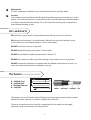
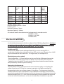
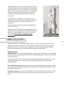
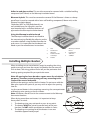
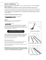
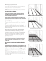
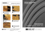
Installation
Manual
IMPORTANT: Read this manual before installation.
Incorrect installation could damage the heater and
invalidate your warranty.
Technical Help line: 0845 345 2288
Your Warmup Undertile Heater has been designed so that installation is quick and
straightforward but as with all electrical systems, certain procedures must be strictly
followed. Please read the manual carefully and check the sizing guide at the back of the
manual to ensure that you have the correct heater for the area you wish to heat.
Contents
Page 1 - 3 Important Points / Do’s and Dont’s
Page 3 - 4 The Heater – Technical Specification
Page 4 - 5 Electrical Provisions
Page 5 - 6 Subfloor Preparation
Page 6
Installing Multiple Heaters
Page 7 - 9 Heater Installation
Page 10
Testing the heater and final connections.
Page 11
Tilers Guide
Page 12
Notes
Page 14
Floor Plan
Page 15
Electrician test sheet
Page 16
Warranty
Page 17
Homeowners Guide
Using the manual
It is important that before during and after the installation that all the requirements are
met and understood.
If the instructions are followed, you should have no problems. If you do require help at
any stage, contact our helpline:
0845 345 2288
You may also find a copy of this manual, wiring instructions, a list of frequently asked
questions and more helpful information on our website: www.warmup.co.uk
Important points
1
Read the manual
More often than not, issues with Warmup® Systems not functioning properly can be
traced directly back to not following the instruction manual. Please ensure that you read
and follow the instruction manual carefully. If you are not sure about any part of the
installation process, please contact the Technical Team for further assistance.
1
2
Check the size of the room
Check and double check that your Installation Plan has the correct measurements. Each
heater is made to a set length and cannot be cut. If the measurements change, this may
affect the size heaters you will require. If you find that the heaters are not the correct
size or you have any queries, contact Warmup for further assistance.
3
Qualified Electrician
As with all electrical projects governed by Part P regulations, all mains electrical
connections must be undertaken by a certified electrician. All work must conform to the
current IEE wiring regulations.
4
RCD (Residual Current Device) - there to protect
The Residual Current Device (RCD) is designed to help prevent electrical shock.
All underfloor heaters must be wired via a 30mA RCD as per BS7671:2008 wiring
regulations.
5
Remember to cover all the heating wire and joints
Both the cold tail and end joint of the heater must not be bent and should be thoroughly
protected from damage. The joints should be recessed into the floor so that they sit at
the same level as the heating element and cannot be damaged.
DO NOT tape over the joints but ensure that they are completely embedded in the tile
adhesive. Ensure that all of the heating wires have been embedded in adhesive and
covered by tiles. Never leave any of the joints or heating element exposed.
6
Thermal blocking
This can occur when heat produced is trapped and cannot escape from the surface of
the floor. DO NOT install under cabinets and other furniture or fixtures with solid bases
that will be permanently installed and attached to the floor.
7
Floor covering
The Warmup Dual-wire heaters are designed for use under ceramic, quarry or natural
stone tiles. If you are using any other type of floor covering, contact the Warmup
Technical Team for further assistance.
8
BEWARE - Damage
Ensure that you plan the layout so that any drilling during tiling will not damage the
heating wire. Care must be taken to ensure that during the course of the installation that
no damage is caused by, for example, falling objects, sharp objects, or walking on the
heating element.
9
Test, Test and Test again!
The system should be tested before, during and after its installation. See page 10 for the
electrician testing guide.
10
Tile Adhesive and Grout
Always use tile adhesive and grout suitable for use with underfloor heating (Must
contain flexible adhesive)
2
11
Allow to dry
DO NOT commence installation on a concrete floor that has not fully dried.
12
Insulate
The insulation levels of a floor will affect both the performance and running costs of the
heater. For minimum heat loss, we recommend the use of the Warmup insulation board
or similar insulated tile backer board. This will reduce the running costs and provide a
more efficient heating system.
Do’s and Don’ts
DO maintain a gap of at least 70mm between the heating wire runs at all times.
DO ensure that the heater is installed at least 50mm from any other heating sources
such as chimneys and conductive parts, such as water pipes.
DO NOT install on stairways or up walls.
DO NOT bend the heating wire under a 25mm radius.
DO NOT install heater if ambient temperature is below 5°C.
DO NOT cut, shorten or allow any of the heating wire to touch or cross at any time.
DO NOT remove the protective wax paper from the double-sided tape all at once , it is
easier to remove the protective wax paper as you go.
The heater Technical Specification
B
A - Coldtail (3m)
B - Coldtail joint
C - Heating element
D - End joint
C
A
D
The heater consists of a fixed length of heating wire terminated at one end by a sealed
end joint and the other by a 3m power supply cable (cold tail).
The cores and earth braid are sliced in a waterproof joint assembly to the supply
conductors and earth conductor of the cold tail.
3
KIT
Cable
Length
(m)
Wattage
Amps
Ohms
150W/m²
approx
90mm
spacing
Prowire 2
22.22
300
1.30
176.38
2m²
Prowire 3
33.33
450
1.96
117.56
3m²
Prowire 4
44.44
600
2.61
88.17
4m²
Prowire 5
55.56
750
3.26
70.53
5m²
Prowire 6
66.67
900
3.91
58.78
6m²
Prowire 10
111.11
1500
6.52
35.27
10m²
Voltage : 230Vac - 50Hz
Minimum Bending radius - 25mm
IP Rating - IPX7
Minimum Spacing - 70mm
Maximum Spacing - 100mm
All Undertile heaters have been tested and approved in accordance with:
EN60335-1-2002
EN60335-2-96-2002
EN50366:2003
Electrical Provisions
As with all electrical projects which are subject to Part P Building Regulations, all electrical work must be carried out by a certified / qualified Part P electrician. All work
must confirm to current IEE wiring regulations - BS 7671:2008.
Installing an RCD
The electrician must install a dedicated 30mA RCD or use an existing RCD. A
combination “double pole switched” fused/spur RCD may be used. No more than 4.8kW
may be connected to each 30mA RCD. For larger loads, use multiple RCDs.
Electrical accessories needed
• Electrical Back Box - A 35mm back box may be used for the all Warmup thermostats.
• Junction Box - If installing more than two heaters a junction box will be required.
• Conduit or plastic trunking- The wiring to the thermostat should be chased into the wall protected by conduit or plastic trunking.
Connecting the thermostat
The thermostat must be connected to the mains electrical supply via a double pole
isolator fused spur or RCD that has a contact separation in all poles providing full
disconnection under over-voltage category III conditions . The thermostat should be
installed within the room to be heated. In most bathroom installations the thermostat
cannot be located within the bathroom itself as the thermostat is IP20 rated and must be
located outside of Zone 2. In such cases the thermostat must be fitted to the outside of
an internal wall of the bathroom, as close to the under floor installation as possible.
4
The installation of more than one product will require
ALL the cold tails to be connected to the thermostat in
parallel and NOT in series. Installations involving more
than two (2) heating wires may require a junction box.
The cold tail consists of three (3) wires: live, neutral
and earth, which should be connected within the
thermostat.
The thermostat is rated up to 16 amps. For larger
installations exceeding 16 amps multiple thermostats
may be required or it may be possible to use a
Contactor.
For further advice Contact the technical department
on 0845-345-2288.
Once the electrical connections have been made, the
electrician must complete the relevant electrical forms
which are to be displayed on or near the consumer
unit as per BS 7671:2008 - 17th Edition wiring
regulations.
Subfloor preparation
When tiling a floor, it is important that the design, construction and preparation of the
subfloor are carried out correctly. All work should comply with the relevant standards
for flooring tiling. This manual is only intended as an outline guide for ceramic tiling.
Further information can be found from the tile adhesive manufacturer.
SUBFLOOR TYPES
Timber Subfloor: Secure existing floorboards. Floor boards should then be over boarded
with a Warmup insulation board (min 10mm) or WBP plywood (Min 18mm) screwed down
at 200mm centres.
Fixing Ply directly to joists will not provide a stable floor finish to accept the tiles. Fixing
18mm tongue and groove then over boarding with WBP plywood or the Warmup
Insulation board.
Un-insulated Concrete: Warmup recommends an insulated tile backer board (min 10mm)
such as the Warmup board is fixed to the concrete base using flexible tile adhesive as per
Manufacture instructions.
Insulated concrete: This must be completely dry, smooth and level. If insulation is under
the concrete slab additional insulation may be required to ensure the efficiency of the
heater.
5
Adhesive and glue residue: This must be removed or covered with a suitable levelling
compound (min 10mm) or the Warmup insulation board.
Bitumen Asphalt: This must be removed or covered. If the Bitumen is there as a damp
proof layer it must be covered with a latex self levelling compound (10mm min) or the
Warmup insulation board.
Chipboard, MDF or OSB (flake boards) are
not suitable bases for tiling this must be
over boarded with a sufficient thickness of
plywood or the Warmup insulation board.
Using the Warmup insulation board
The Warmup insulation boards are fitted to
the concrete using flexible tile adhesive and to
a wooden subfloor using flexible tile adhesive
and screws. It is important that the boards are
fitted as per the manufactures instructions.
1.
2.
3.
4.
Tiles
Flexible Tile
Adhesive
Prowire Double
sided Tape
Prowire
Installing Multiple Heaters
When installing two or more heaters, begin by reading the sizing
guide to ensure you have the correct size heaters for the area you
wish to heat. The sizing guide will also tell you the perimeter and
heating spacing required for your particular room.
Note: All spacing has been based on square areas for calculation
purposes, Therefore, actual spacing will vary according to the
shape of the area to be heated.
Mark out the spacings and lay the first heater. Do not cover with the
fibre glass tape at this point as you may wish to adjust the spacing
later on.
Lay the second heater in the remaining area using the same perimeter
and heating wire spacing as the first heater.
Note: All heaters should start in the same area next to the Warmup
thermostat location.
When laying more than one heater, it is important to keep
these points in mind :
1. The heating wires may not touch or cross at any point.
2. The heaters MUST be joined in parallel only at the junction box. Do NOT attach one heater to another in series.
3. The heating wire spacing for all the heaters in an area
should be approximately equal.
6
5.
6.
7.
Warmup Insulation
Board
Flexible Tile
Adhesive
Subfloor
Heater Installation
Ensure that you have completed the necessary subfloor preparations specified on page 5
before proceeding.
Before commencing installation, test the resistance of the heater (see page 10).
Calculate the total area (m²) of you room deducting any areas where units are to be fitted or
the heating element will not be laid. Allow a 50mm perimeter.The table on page 4 can be
used as a guide as it shows approximate m2 coverage of each cable when laying at 150W/m2
(spacing 90mm).
Formula Calculating the required spacing
Area to be heated (m²) x 1000 = spacing(mm)
Cable Length
Example
Room = 4m² (2m x 2m)- Less perimeter of 50mm
Area to be heated - 1.9m x 1.9 m = 3.61m²
3.61m² x 1000 = 81mm
44m
In order to attach the double-sided tape to the subfloor
you must ensure that the surface is dry, clean and free
from dust. If the tile adhesive used requires a primer, follow
the manufacturer’s instructions.
Do not commence installation on a
concrete floor that has not fully dried
Smooth, clean and dry floor
Attach the double-sided tape at an approximate distance
of about 50cm. The tape should be laid in the oppposite
direction to the heating element runs, observing the
50mm perimeter from the wall.
Reinforcing loop area
In the areas where the heating wires loop a second line
double-sided adhesive tape should be attached.
Attach the double sided tape to the floor
Each loop should sit fully on the adhesive tape to prevent
the wire from lifting.
NOTE: DO NOT space the the heating cable closer than 70mm
or further than 100mm apart.Spacing should be kept uniform
to ensure an even spread of heat across the area.
Mark out spacing intervals
7
Removing the protective film
Loosen the protective film from the tape in the area
where you want to start the installation.
NOTE: Do not remove all of the protective film at
the start of the installation.
Gently pull the power supply cable from the box.
Do not remove the spool from the box as this will
cause the heating wire to twist.
Remove a section of the protective film
After 3 metres of cable have been removed, you will
reach the point at which the power supply cable joins
the heating wire.
The joint should be secured to the floor at the start
point.
The wire should be laid at the correct spacings in
parallel lines back and forth crossing over the runs of
double sided tape.
Lay wire out from start point
Adjust the spacing between the cable if required
to ensure that the heating cable/s fit your room.
In order to achieve even coverage of the balance of
the area to be heated, you may at this stage need
to adjust some of the wire spacing that you have
previously secured.
Once the heating wire layout has been completed,
Apply the fibre glass tape over the runs of doublesided tape.
Do not cover the entire cable with the fibre glass
tape.
Lay out wire in parallel lines
Depending on the requirements of the tiler, it may be
necessary to chisel out or “chase” short channels in the
subfloor to minimise the increased height presented
by the power cable, the end joint and the floor probe
conduit.
Before chiselling the area, ensure that the heating
wire and power supply cable are out of the way. Fit
the power supply cable into the channels and secure
with fixing tape.
Fix fibre glass tape
8
Depending on the requirements of the tiler, it may be
necessary to chisel out or “chase” short channels in the
subfloor to minimise the increased height presented
by the power cable, the end joint and the floor probe
conduit.
Before chiselling the area, ensure that the heating
wire and power supply cable are out of the way. Fit
the power supply cable into the channels and secure
with fixing tape.
Step 4:
Install the floor sensor and conduit supplied with
the Warmup thermostat.
Lay the floor sensor wire at least 300mm from the
wall. The floor sensor should be centred between
two of the heating element runs and should extend a
minimum of 150mm into the heated area.
The floor sensor should be installed into a flexible
conduit to allow for a new sensor to be easily fitted
should a fault develop.
Please note, the sensor conduit may be taken into a
connection box where it may be extended up to 50
metres to the thermostat location. The sensor must be
run in a separate conduit -it must be separated from
other cabling.
When positioning the sensor avoid hot water pipes
in the floor or draughty places such as external
doorways as this may affect the temperature reading.
9
30cm from wall
Install the Warmup® Thermostat
The power cable consists of conductors coloured brown(live), Blue(neutral) and
green/yellow (earth). These should be connected in accordance with current wiring
regulations.
Ensure that the heaters have been tested before any connections are made to the
electrical supply.
Please review information on page 4 & 5 before proceeding.
Test the heater(s)
You must test the heater before during and after installation of the final floor finish to
ensure that the heaters have not been damaged during the installation.
Using a multimeter test the resistance of each individual heating element.
Set the multimeter to 200 ohms and test the heater across the Live and Neutral.
At 20°C between live and Neutral the heater should read
Model
Resistance
PROWIRE 2
177 ohms
PROWIRE 3
118 ohms
PROWIRE 4
88 ohms
PROWIRE 5
71 ohms
PROWIRE 6
59 ohms
PROWIRE 10
35 ohms
Check resistance using multi-meter
A +/- 5% Ohm reading tolerance is allowed under manufacturing guidelines.
If the heater resistance reading is open circuit or above/below the allowed tolerance.
DO NOT TILE contact the technical helpline on 0845 345 2288.
All test results must be recorded on the control card at the back of the manual.
NOTE: DO NOT WIRE THE HEATING ELEMENT TO THE MAINS WHILE THE HEATING
ELEMENT IS STILL ON THE REEL.
10
Tiling the floor
The tile adhesive and gout must include an additive for flexibility and be suitable for use
with underfloor heating. Refer to the adhesive manufacture’s instructions for usage.
2 part flexible adhesive is best.
Check that the heating element is secure. Tile as normal, taking care not to damage or
dislodge the heating wire with the trowel or with tiles.
If tiling with mosaic slate or similar tiles it is
advisable to cover the heating wire with a
latex self -levelling compound before tiling.
When using a notched trowel, gently comb
the adhesive in straight lines in the same
direction as the runs of wire.
If possible use a plastic trowel.
Do not allow the trowel to make contact with
the heating wire while applying the adhesive.
Use sufficient adhesive to ensure that there
are no voids or hollows under the tile.
If a tile has been positioned incorrectly, take
great care not to damage the heating wire
when lifting.
Remember that tiles must not be lifted once
the adhesive is dry, as this will damage the
heating wire. Do not store or cut tiles on top
of the heating wire. Do not allow chippings or
dust to contaminate the floor during tiling.
Care must always be taken not to damage the
wire during the tiling process. Use a piece of
carpet or a dust sheet as a crawl-board to prevent the heating wire being damaged by your
feet or knees during the tiling process.
Use correct adhesive and grout
Tile as usual
During the tiling process, check the resistance
of the heater with a multimeter at regular
intervals.
If the heater goes open circuit DO NOT
CONTINUE - call the technical helpline 0845
345 2288.
Grout the floor as soon as possible as per the
manufactures instructions.
Do not store tiles on heater
11
Notes
12
Floor Plan
13
13
Floor Plan
14
15
Warranty
Terms and conditions apply
REGISTER YOUR HEATER ONLINE AT: www.warmup.co.uk
THE LIFETIME ELEMENT OF THIS GUARANTEE DOES NOT EXTEND TO THERMOSTATS WHICH ARE COVERED
BY SEPARATE GUARANTEES. THIS GUARANTEE DOES NOT AFFECT YOUR STATUTORY RIGHTS.
Warmup® Undertile Heater is guaranteed by WARMUP PLC (“Warmup”)to be free from defects in materials and
workmanship under normal use and maintenance, and is guaranteed to remain so subject to the limitations and
conditions described below.
The UNDERTILE HEATER is guaranteed for the LIFETIME of the floor covering under which it is fitted, except as
provided below (and your attention is drawn to the exclusions listed and the end of this guarantee).
The lifetime guarantees applies:
1. Only if the unit is registered with Warmup within 30 days after purchase. Registration can be completed
online at www.warmup.co.uk. In the event of a claim, proof of purchase is required, so keep your invoice
and receipt - such invoice and receipt should state the exact model that has been purchased ; and
2.
Only if the heater has been earthed and protected by a Residual Current Device (RCD) at all times.
Thermostats are guaranteed for a period of 3 YEARS from the date of purchase, except as provided below.
Neither guarantee continues if the floor covering over the heater(s) is damaged, lifted, replaced,repaired or
covered with subsequent layers of flooring.
This guarantee period begins on the date of purchase. Registration is confirmed only when confirmation is sent
by Warmup PLC. During the period of guarantee Warmup will arrange for the heater to be repaired or (at its
discretion) have parts replaced free of charge. The cost of repair or replacement is your only remedy under this
remedy under this guarantee which does not affect your statutory rights.
Such costs does extend to any cost other than direct costs of repair or replacement by Warmup and does not
extend to costs of relaying or repairing any floor covering or floor.
If the heater fails due to damage caused during installation or tiling, this guarantee does not apply. It is therefore
important to check that the heater is working (as specified in the installation manual) prior to tiling.
WARMUP PLC SHALL IN NO EVENT BE LIABLE FOR INCIDENTAL OR CONSEQUENTIAL DAMAGES, INCLUDING BUT
NOT LIMITED TO EXTRA UTILITY EXPENSES OR DAMAGE TO PROPERTY.
SafetyNet Installation Guidelines:
If you make a mistake and damage the new heater before laying the floor covering,
return the damaged heater to Warmup within in 30 days along with your original
dated sales receipt. WARMUP WILL REPLACE ANY PRE-TILED HEATER (MAXIMUM 1
HEATER) WITH ANOTHER HEATER OF THE SAME MAKE AND MODEL - FREE.
TM
Please note:
(i) Repaired heaters carry a 5 year warranty only. Under no circumstances is Warmup responsible for the repair or
replacement of any tiles / floor covering which may be removed or damaged in order to affect the repair.
TM
(ii) The SafetyNet Installation Guarantee does not cover any other type of damage, misuse or improper
installation due to improper adhesive or subfloor conditions. Limit of one free replacement heater per customer
or installer.
(iii) Damage to the heater that occurs after tiling, such as lifting a damaged
tile once it has set, or subfloor
TM
movement causing floor damage, is not covered by the SafetyNet Guarantee.
Register your Warmup® warranty online at www.warmup.co.uk
16
Homeowners Guide
Thank you for choosing to install Warmup underfloor heating we are sure that you will enjoy living
with the comforts of underfloor heating in your home.
End User Checklist
Please check that you have the following documents.
1. Floor Plans
2. Electrical Test Sheets
3. Thermostat Instructions
If you have not received any of the above documents contact your installer who will be able to
provide the relevant information.
User Information
You may want to test that the heaters are working correctly prior to programming the thermostat
fully. This can be done by setting the thermostat into a manual mode and allowing the appropriate
time for the floor to heat up.
Always allow 7-10 days for tile adhesive/ grout to dry fully before switching the heaters on.
Heat up times
Subfloor
Heat Up time (approx)
WBP plywood
45min
WBP plywood with Warmup Insulation
Board
20min
Insulated Concrete (insulation under
screed)
2-5 hours
Concrete with 10mm Warmup Board
25min
un-insulated Concrete
2-8 hours
Thermal blocking
This can occur when heat produced is trapped and cannot escape from the surface of the floor. Do
not install under furniture or fixtures with solid bases that will be permanently installed or attached
to the floor. Any furniture should have a min of 10mm clearance. Rugs should be avoided, as they
act as an insulator reducing the efficiency of the installation.
Energy saving
A few tips to save energy
•
Use the thermostat in a program mode to ensure that the heaters are only heating the floor
when needed.
•
DO not set the thermostat temperature too high. 28°C is more than adequate for most installations.
•
Ensure that the thermostat is programmed to be off at times when the heaters will not be
needed.
If you require further assistance contact Warmup Technical on 0845 345 2288.
17
Warmup Plc
702 Tudor Estate
Abbey Road, London
NW10 7UW
0845 345 2288
0845 345 2299
[email protected]
www.warmup.co.uk
Scan and visit our website
V2.0
The WARMUP word and associated logos are trade marks. © Warmup Plc.2007-Regd.TM nos. 1257724,4409934,4409926,5265707.E & OE.