1
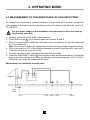
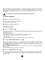
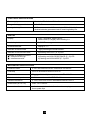
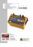
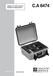
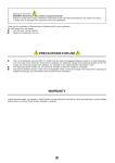
■
CONTRÔLEUR DE TERRE
■
EARTH TESTER
■
ERDUNGSPRÜFER
■
STRUMENTO DI CONTROLLO DELLA TERRA
■
CONTROLADOR DE TIERRA
C.A 6423
FRANCAIS
Mode d'Emploi
ENGLISH
User's Manual
DEUTSCH
Bedienungsanleitung
ITALIANO
Libretto d'Istruzioni
ESPANOL
1
Manual de Instrucciones
English
Meaning of
symbol: Warning!
Consult the User’s manual before using the instrument.
You have just acquired an Earth Tester and we thank you for your confidence.
To get the best service from your instrument:
- read carefully this user’s manual,
- respect the safety precautions in it,
- stick the label corresponding to your language on the back of the instrument.
SAFETY IN USE
■ Before connecting up the C.A 6423, check that no dangerous voltage is present at the
earth to be measured.
■ Before opening the battery compartment, ensure that no measurement lead is connected
to the instrument.
WARRANTY
Unless notified to the contrary, our instruments are guaranteed from any manufacturing
defect or material defect. They do not bear the specification known as the safety specification.
Our guarantee, which may not under any circumstances exceed the amount of the invoiced
price, goes no further than the repair of our faulty equipment, carriage paid to our workshops.
It is applicable for normal use of our instruments, and does not apply to damage or destruction
caused, notably by error in mounting, mechanical accident, faulty maintenance, defective
use, overload or excess voltage.
Our responsability being strictly limited to the pure and simple replacement of the faulty parts
of our equipment, the buyer expressly renounces any attempt to find us responsible for
damages or losses caused directly or indirectly.
Our guarantee is applicable for twelve (12) months after the date on which the
equipment is made available. The repair, modification or replacement of a part during the
guarantee period will not result in this guarantee being extended.
15
SUMMARY
Page
16
1. PRESENTATION
......................................................................................................................................................
...........................................................................................................................................................
17
3. OPERATING MODE ..............................................................................................................................................
3.1. Measurement of resistance of an earth point ..................................................................
3.2. Measurement of resistance ...........................................................................................................
3.3. Fault signals ..............................................................................................................................................
18
18
19
20
4. SPECIFICATIONS
...................................................................................................................................................
21
5. MAINTENANCE .........................................................................................................................................................
5.1. Normal cleaning .....................................................................................................................................
5.2. Calibration check ...................................................................................................................................
5.3. Repair ............................................................................................................................................................
24
24
25
25
6. TO ORDER
26
2. DESCRIPTION
....................................................................................................................................................................
1. PRESENTATION
Autonomous and watertight, this tester is a worksite instrument designed for earth resistance
measurements. It is particularly suited to measurements in difficult conditions such as when
there are stray voltages present, high telluric currents, high value auxiliary electrode
resistances, etc...
For ease of use, this instrument has the following features:
■ a single press button to trigger the measurement
■ an autoranging system for measurement range switching
■ a large digital display which is readable even in shadow
■ three indicators that signal the presence of faults which can lead to errors during measurement
■ three colour coded screw terminals to simplify connection of leads
■ an attached connection rod
16
2. DESCRIPTION
1
2
3
4
5
6
7
8
9
10
11
Measurement input terminal E (green)
Measurement input terminal S (blue)
Measurement input terminal H (red)
Attached rod S - H for 2 wire resistance measurement
2000 count digital LCD
Low battery indicator
Reverse connection indicator
Current circuit fault indicator (E - H)
Voltage circuit fault indicator (E - S)
Indicator of presence of interference on voltage circuit (E - S)
Measurement press button
2
1
4
3
6
8
5
11
9
10
7
17
3. OPERATING MODE
3.1 MEASUREMENT OF THE RESISTANCE OF AN EARTH POINT
To measure the resistance of an earth conductor, the so-called "62% method" is in general
recommended. This measurement requires the use of the items in the Earth Kit (see Ch.6:
TO ORDER).
Cut the power supply to the installation and disconnect it from the earth by
opening the earth bar!
1. Connect terminal E to the earth to be measured.
2. Check that the bar 4 is not present between terminals S and H.
3. Drive in (completely if possible) the input earth rod H at a distance "a" from the earth point
(E) to be measured.
Note: this distance is further for a deep and extended earth point (larger range of influence).
4. Drive in the rod S at 62% of the distance between the earth E and the rod H (the rods S,
H and the earth point must be in line).
5. Connect the rods to their respective terminals with the leads.
6. Press the "MEASURE" button 11 and hold the button during measurement. Check that
none of the three indicators are flashing, otherwise, check the wiring (see Ch.3.4: FAULT
SIGNALS) and make the measurement again.
Measurement of resistance of earth point
earth bar
E
E
S H
S''
S
S'
H
earth
point
0%
52 %
18
62 % 72 %
100 %
Checking the measurement
7. Note the displayed value.
8. Wait for a few moments and then re-measure.
9. Move rod S by 10% towards H, along the line between the earth point E and the rod H.
Measure and note the result.
10. From its initial position, move rod S by 10% towards E, along the line between the earth
point E and the rod H.
If the three values are of the same order of magnitude, the earth measurement is correct. If
not, increase the distance "a" and repeat the measurements.
Do not forget to reconnect the earth point after the measurement.
3.2 MEASUREMENT OF RESISTANCE
This measurement can be performed to determine the coupling resistance between two earth
points. For example, between the neutral and ground earth points (EDF distribution).
Cut the power supply of the installations. For measurement of the coupling
resistance, disconnect the earths!
1. Short-circuit terminals S and H using the bar provided 4 .
2. Connect terminal E to the earth of the ground, and terminal H to the earth of the neutral.
3. Press the "MEASURE" button 11 and hold down until the measurement is displayed.
Check that none of the three indicators are flashing, otherwise check the connections (see
Ch.3.4: FAULT SIGNALS) and repeat the measurements.
2-wire resistance measurement
E
earth
bar
S H
earth 1
earth
bar
earth 2
19
NB: In the case of low value resistances, it becomes necessary to take into account the
resistance of the leads (approx. 22.5 mW /m for those supplied as accessories). To overcome
the resistance of the leads, we advise the use of a (4 pole) Earth/Resistivity Tester, on 4-wire
connection.
Do not forget to reconnect the earth points after measurement.
3.3 FAULT SIGNALS
■ Display of a negative measurement
Reversal of rods H and E or rods S and E
Re-connect the leads correctly
■ Displayed measurement value is 1--Overrange (R > 2000 W )
Check the connections
■ Flashing of FAULT light 8
Fault in current circuit (E - H). Flashing indicates that the voltage between the terminals E and
H is greater than 30 Vpeak.
This may mean that:
- the resistance of the current circuit between E and H is too high,
- the interference voltage in the circuit (E - H) is too high,
- the fuse is blown.
Check the rods, the leads, the connections and the fuse (see Ch.5.1.3).
■ Flashing of HIGH RESISTANCE indicator 9
Fault in the voltage circuit (E - S). At the start of the measurement, the instrument
automatically checks the resistance between E and S. If this is greater than 50 kW , the
indicator 9 begins to flash. This means that the measurement is likely to be very affected by
the resistance of the voltage circuit.
NB: The indicator flashes throughout the measurement, even if the resistance falls below
50 kW during it.
Check the rods, the leads and their connections.
■ Flashing of HIGH NOISE indicator 10
Presence of interference voltages in the voltage circuit. Flashing indicates noise greater than
13 Vpeak between terminals E and S. These interference signals disturb the measurement.
Move the rods.
20
4. SPECIFICATIONS
REFERENCE CONDITIONS
Temperature
23°C ± 3 K
Relative humidity
45% < RH < 55%
Supply voltage
10.5 V ± 0.2 V
Auxiliary resistances RH, RS and RE
nil
AC and DC interference voltages
nil
Electric field
< 1 V/m
Magnetic field
< 40 A/m
METROLOGICAL SPECIFICATIONS
Measurement range
(automatic range)
Resolution
Measurement current
(square signal 128 Hz)
Accuracy
Empty voltage
0.00...19.99 W
0.01 W
10 mA
± 2%rdg ±1 pt
£ 42 Vpeak
20.00...199.9 W
0.1 W
1 mA
± 2%rdg ±1 pt
£ 42 Vpeak
200.0...1999 W
1W
100 µA
± 2%rdg ±3 pt
£ 42 Vpeak
Response time
between 4 and 8 s depending on measurement conditions
DISTORTION QUANTITIES
Operating limits
Max variation
-10...+55°C
± (1% rdg ± 1 pt) per 10°C
Temperature
Relative humidity
20...90%
± 2% rdg ± 5 pt
Operating voltage
8.8...12.5 V
± (1% rdg ± 1 pt) per Volt
50 kW
± 1% rdg per 10 kW ± 4 pt
0.00...19.99 W
30 kW
± 1% rdg per 10 kW ± 2 pt
20.00...199.9 W
30 kW
± 1% rdg per 10 kW ± 2 pt
200.0...1999 W
50 kW
± 1% rdg per 10 kW ± 2 pt
0...20 V (3)
negligeable
AC interference voltages on H
0...23 Vrms or 32 Vpeak
± 2% rdg ± 2 pt
AC interference voltages on S
0...9 Vrms or 13 Vpeak
± 0.5% rdg ± 2 pt
Voltage circuit load (1)
Current circuit load (2)
DC voltage
(1) Resistance measured or resistance of rod E + resistance of rod S + resistance of leads
(2) Resistance measured or resistance of rod E + resistance of rod H + resistance of leads
(3) Possible flashing of HIGH RESISTANCE indicator above 4.5 V
21
ELECTRICAL SPECIFICATIONS
Power supply
8 batteries R6 alkaline 1.5 V or 8 accumulators
Range of voltage permitted
8.8...12.5 V
Average battery life
1800 measurements of 15 seconds (at 23°C ± 3 K, with 8
alkaline batteries) permanent test of remaining battery life.
DISPLAY
Display
LCD, 7 segments, height 18 mm,
2000 counts (3½ digits), direct reading in W
Low battery indicator
"LO BAT" message
Overload indicator
display of 1 ---
Indicator of lead reversal
- sign preceding the measurement
Indicator of current circuit fault
by flashing red FAULT (E -H) LED
Indicator of voltage circuit fault
■ Resistance too high
■ Interference noise
by flashing red HIGH RESISTANCE (E - S) LED
by flashing red HIGH NOISE (E - S) LED
MECHANICAL SPECIFICATIONS
Protection index
IP 54 in accordance with IEC 529 and NF EN 60 529
Free drop
25 cm in accordance with IEC 68-2-32
Shock resistance
50 gn (gn = 9.81 m/s²) in accordance with IEC 68.2.27
Resistance to impacts
IK 04 in accordance with NF EN 50 102
Vibration resistance
± 1 mm, from 10 to 55 Hz in accordance with IEC 68.2.6
Dimensions (W x H x D)
238 x 136 x 150 mm
Connection of leads
on 3 colour coded terminals for f 4 mm banana plugs or
6 mm spade clips
22
CLIMATIC CONDITIONS
Humidité enin%%
HRRH
Humidity
100
90
80
70
60
50
40
30
20
10
Temperature
Température
- 40
- 20
0
20
40
Domaine nominal
de référence
Nominal
reference
range
Domaine d'utilisation
Operating
range
Domaine de
stockage
Storage
range
CONFORMITY WITH STANDARDS
Electrical safety (in accordance with IEC 1010-1)
- Double insulation
- Installation category III
- Degree of pollution 2
- Service voltage 42 Vpeak
Electromagnetic compatibility
■ Emission (in accordance with EN 50081-1)
■ Immunity (in accordance with EN 50082-1)
23
60
80
in°C
°C
en
5. MAINTENANCE
For maintenance, use only specified spare parts. The manufacturer will not be
held responsible for any accident occurring following a repair done other than
by its after sales service or approved repairers.
5.1 NORMAL CLEANING
5.1.1 Cleaning
Preferably use a damp cloth or a sponge slightly moistened with soapy water. Do not use
alcohol, petrol or other products based on hydrocarbons.
5.1.2 Replacing batteries or accumulators
The test of remaining battery life is automatic and permanent. At the first appearance of the
"LO BAT" message, the instrument still has sufficient power for a few measurements. The
batteries must be changed within a short time.
Before changing the batteries, ensure that no lead is connected to the instrument.
All the batteries must be replaced at the same time.
Do not mix together batteries and accumulators.
Undo the attached screws located under the instrument which give access to the battery
compartment. Replace the 8 used batteries by 8 new ones of the same type, according to the
polarity. Refit the cover of the battery compartment.
5.1.3 Replacing the fuse
The indicator may be flashing because the fuse protecting the current circuit has blown. To
check, short-circuit terminals E and H (with bar 4 open and the measurement leads
disconnected). If the FAULT light still flashes, the fuse must be changed. To do this, remove
the cover of the battery compartment, unscrew the fuse holder and pull out the fuse. Replace
it with a new one of the same type (0.1 A - 250 V). Refit the battery cover.
5.1.4 Storage
In case of prolonged non-use, remove the batteries from their compartment. Store the
instrument only in the specified environmental conditions (see Ch. 4: SPECIFICATIONS).
24
5.2 CALIBRATION CHECK
It is essential that all measuring instruments are regularly calibrated.
For occasional daily use, we recommend that an annual calibration be carried out.
When the instrument is used continuously every day, we recommend that calibration is
carried out every 6 months.
For calibration and repair of your instrument, please contact our COFRAC-BNM accredited
laboratories :
- CHAUVIN ARNOUX Pont l’Evêque- France :
- MANUMESURE Lyon - France :
(33) 31 64 51 11
(33) 78 26 68 04
Or the CHAUVIN ARNOUX subsidiary or Agent in your country
5.3 REPAIR
Repairs under or out of guarantee: Please return the product to your distributor.
25
6. TO ORDER
■ C.A 6423 EARTH TESTER ...........................................................................................
supplied with batteries, carrying strap and User’s manual
Accessory for C.A 6423:
■ Shoulder bag ............................................................................................................................
ref. P01.1270.13
ref. P01.2980.06
Spares for C.A 6423:
■ Carrying strap .......................................................................................................................... ref. P01.2980.05
■ HBC fuse 0.1 A - 250 V (pack of 10) ...................................................................... ref. P01.2970.12
■ Battery 1.5 V alkaline LR6 (pack of 8) ................................................................... ref. P01.1007.74
Measurement accessories:
■ PRESTIGE EARTH ACCESSORIES Kit
Semi-rigid bag comprising:
- two T shaped smooth rods
- 100 m of red lead on reel
- 60 m of blue lead on reel
- 10 m of green lead on reel
- ground of 1 kg
.............................................................
Spares for measurement accessories:
■ Semi-rigid bag .........................................................................................................................
■ Smooth T shaped rod ........................................................................................................
■ 100 m red lead on reel ......................................................................................................
■ 60 m blue lead on reel .......................................................................................................
■ 10 m green lead on reel ...................................................................................................
26
ref. P01.1018.24
ref.
ref.
ref.
ref.
ref.
P01.2980.26
P01.1018.29
P01.2950.45
P01.2950.44
P01.2950.41