1
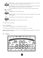
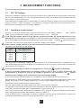
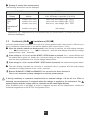
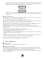
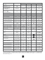
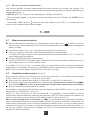
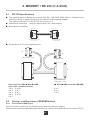
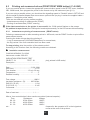
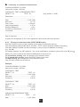
■
■
■
■
■
C.A 6541
C.A 6543
Mégohmmètres
Megohmmeters
Megohmmeter
Megaohmmetri
Megaóhmetros
FRANÇAIS
ENGLISH
DEUTSCH
I TA L I A N O
E S PA N O L
Notice de fonctionnement
User's manual
Bedienungsanleitung
Libretto d’Istruzioni
Manual de Instrucciones
1
English
Meaning of the ! symbol
Warning ! Please refer to the User’s Manual before using the instrument.
In this User’s Manual, the instructions preceded by the above symbol, should they not be carried out
as shown, can result in a physical accident or dammage the instrument and the installations.
Meaning of the
symbol
This device is protected by a double insulation or by a reinforced insulation. No linking is required from
the protection earth terminal to ensure the electrical security.
Meaning of the
symbol
WARNING! Risk of electric shock.
The voltage of parts indicated with this symbol can be ≥ 120 V DC. For safety reasons, this symbol
lights up on the LCD screen as soon as a voltage is generated.
Thank you for purchasing a C.A 6541 or C.A 6543 megohmmeter.
To get the best service from this instrument :
■ read this user’s manual carefully
■ respect the safety precautions detailed
!
SAFETY PRECAUTIONS
!
■
Observe the conditions for use : temperature, humidity, altitude, pollution level and place of use.
■
This instrument can be used on category III installations with voltages not exceeding 600 V in
relation to the earth. Category III meets with the severe reliability and environmental requisites
corresponding to permanent use on fixed industrial installations (see EN 61010 Ed. 95)
■
Use connection accessories with overvoltage category and service voltage that are above or equal
to that of the test instrument (600 V Cat III). Only use accessories that comply with the safety
standards (EN 61010-2-032).
■
Observe the correct value and type of fuse (see § 8.1.3) at risk of damaging the device and rendering
your guarantee void.
■
Select the OFF position on the selector switch when the device is not in use.
■
Check that none of the terminals are connected and that the selector switch is set to OFF before
opening up the instrument.
■
All repairs and metrological verification procedures must be carried out by qualified personnel.
32
CONTENTS
1. PRESENTATION ............................................................................................................................. 34
1.1 Megohmmeters ...................................................................................................................... 34
1.2 Accessories ............................................................................................................................ 34
2. DESCRIPTION ................................................................................................................................ 36
2.1 Unit overview .......................................................................................................................... 36
2.2 Display .................................................................................................................................... 37
3. MEASUREMENT FUNCTIONS ...................................................................................................... 39
3.1 AC / DC Voltage ..................................................................................................................... 39
3.2 Insulation measurement ......................................................................................................... 39
3.3 Continuity (40 Ω
) / resistance (400 kΩ) .......................................................................... 40
4. SPECIAL FUNCTIONS .................................................................................................................. 41
4.5
4.6
4.7
2nd Button .............................................................................................................................. 41
V-TIME /
Button ................................................................................................................. 41
R-DAR-PI / R (t) Button .......................................................................................................... 41
✻ / ALARM Button ................................................................................................................. 43
▼
4.1
4.2
4.3
4.4
/ SMOOTH Button ............................................................................................................. 44
▲
▼ Button ................................................................................................................................ 44
SET- UP function .................................................................................................................... 44
5. USE ................................................................................................................................................. 47
5.1 Measurement procedure ........................................................................................................ 47
5.2 Insulation measurement ......................................................................................................... 47
5.3 Continuity measurement ........................................................................................................ 48
5.4 Resistance measurement ...................................................................................................... 48
5.5 Capacitance measurement .................................................................................................... 48
6. MEMORY / RS 232 (C.A 6543) ...................................................................................................... 49
6.1 RS 232 Specifications ............................................................................................................ 49
6.2 Saving / recalling values ( MEM/MR button) ......................................................................... 49
6.3 Printing out measured values (PRINT/PRINT MEM button) (C.A 6543) ............................... 52
6.4 Printing with the serial-to-parallel adapter ............................................................................. 54
7. SPECIFICATIONS .......................................................................................................................... 54
7.1 Reference conditions ............................................................................................................. 54
7.2 Specifications per function ..................................................................................................... 54
7.3 Power supply .......................................................................................................................... 58
7.4 Environmental conditions ....................................................................................................... 58
7.5 Mechanical specifications ...................................................................................................... 59
7.6 Conformity to international standards .................................................................................... 59
8. MAINTENANCE .............................................................................................................................. 59
8.1. Upkeep ................................................................................................................................... 59
9. WARRANTY ................................................................................................................................... 60
10. TO ORDER ..................................................................................................................................... 61
11. ATTACHMENT .............................................................................................................................. 152
11.1 Front view ............................................................................................................................. 152
11.2 Examples of applications ..................................................................................................... 153
11.3 Accessories .......................................................................................................................... 156
33
1. PRESENTATION
1.1
Megohmmeters
Megohmmeters C.A 6541 and C.A 6543 are portable instruments, each housed in robust casing with
lid and operating on batteries (C.A 6541), or on a rechargeable battery and the mains (C.A 6543).
They can be used to measure :
■
voltage
■
insulation
■
continuity
■
resistance
■
capacitance
These megohmmeters contribute to the safety of electrical installations and equipment.
Their functioning is micro-processor controlled, for data acquisition, processing, displaying measurements,
memory storage and the printing of results (C.A 6543).
They offer a number of advantages such as:
■
digital filtering of insulation measurements,
■
running measurements with the help of a remote control probe,
■
automatic voltage measurement in all functions,
■
automatic detection of external AC or DC voltages on the terminals, before or during measurements,
which prohibits or stops measurement, no matter what function you’re in,
■
threshold programming in each function, triggering audible alarms,
■
timed control of measurement duration,
■
fuse protection of the device, with defective fuse detection,
■
operator safety thanks to the automatic discharge of the residual high voltage on the tested device,
■
automatic device switch-off to save the batteries (C.A 6541) or the rechargeable battery (C.A 6543)
■
the battery wear indicator (C.A 6541) or the battery charge status indicator (C.A 6543),
■
a large back-lit LCD with comprehensive range of symbols, easily read by the user.
The C.A 6543 has the following additional features:
■
Integral rechargeable battery (recharged from the mains)
■
Operation directly powered from the mains
■
128 kB memory, real time clock and serial interface
■
Piloting of the instrument from a PC (with the optional MEGOHM VIEW software)
■
Printing in RS 232 or Centronics mode
1.2
Accessories
■ Remote control probe (optional, see § 11.3)
This probe plugs in via a specific connector.
It can be used to carry out all measurements, the yellow button operates in just the same way as the
device’s START/STOP button.
A push button, on the back of the probe, enables you to light up the measurement point (approx. 500 lux
illumination) : a useful feature since insulation measurements are made on dead installations, hence in
darkness.
34
■ “Megohm View” PC software (option for the C.A 6543)
The PC software makes it possible to:
- retrieve data from memory, to plot graphs of the changes in insulation as a function of the time over
which the test voltage is applied, R (t),
- to print out protocols of personalised tests depending on the user’s needs,
- to create text files for use on spreadsheets (ExcelTM, ...),
- to set up and control the instrument entirely via the RS 232.
The minimum configuration recommended for the PC is a 486DX100 processor.
■ Serial printer (option for the C.A 6543)
This compact printer enables you to print out test results directly on-site, whether you’ve saved them or
not.
■ Serial-to-parallel adapter
The RS232/Centronics adapter available as an option makes it possible to convert the serial interface
(RS232) into a parallel printer interface (Centronics), which enables direct printing of all measurements
on A4 format office printers without having to resort to using a personal computer.
35
2. DESCRIPTION
2.1
Unit overview
Refer to the pictures of the device in Appendix § 11, found at the end of this user’s manual.
2.1.1
➁
➂
➃
3 x 4 mm ∅ safety terminals labelled: “ + ”, “ G “ and “ - “
Next to the “ - “ terminal, there are 2 additional terminal contacts for the connection of the remote
control probe (3 contact connector)
Rotary selector switch with 9 positions:
■ Off : instrument is off
■ MΩ - 50 V
: insulation measurement up to 200 GΩ
■ MΩ - 100 V
: insulation measurement up to 400 GΩ
■ MΩ - 250 V
: insulation measurement up to 1 TΩ
■ MΩ - 500 V
: insulation measurement up to 2 TΩ
■ MΩ - 1000 V : insulation measurement up to 4 TΩ
■ 400 KΩ : resistance measurement
■ 40 Ω
: continuity measurement
■ SET-UP :set-up of the device configuration
1 yellow START / STOP button: start/stop of the measurement
6 buttons (C.A 6541) or 8 buttons (C.A 6543) in elastomer, each with a first and a second function:
Selection of the second function (in yellow italics below each button)
2nd
First function: before insulation measurement use to choose the type of measurement
desired from amongst normal measurement, the dielectric absorption ratio (DAR)
R-DAR-PI and the polarisation index (PI). After measurement it displays R, DAR, PI and
capacitance (µF).
Second function: Show / hide the interval values of insulation resistance, test voltage
R (t)
and time-stamping, following a time-controlled test (buttons V-TIME and ▲
▼ can also be
used).
V-TIME
✻
ALARM
▼
➀
C.A 6541 and C.A 6543
First function: When measuring insulation, it displays the time elapsed since the
beginning of the measurement, then the exact voltage generated. When carrying out
Resistance or Capacitance measurement, this button has no effect. In MR (memory
recall), it displays the date and the time at which the measurement was memorised, the
exact test voltage and the OBJ : TEST number.
Second function: activation/deactivation of “time-controlled” test mode
First function: to turn display back-lighting on and off
Second function: to activate/deactivate the alarms programmed in SET-UP
First function: to select a parameter to be modified
SMOOTH Second function: to stop/start smoothing of displayed values during insulation testing
36
▲
▼
First function: to increase the flashing parameter being displayed. To move about the
list of interval insulation measurements, in the R(t) function.
Second function: to decrease the flashing parameter being displayed. To move about
the list of interval insulation measurements, in the R(t) function.
If the ▲ and ▼ buttons are held down, the movement between parameters is fast.
■ C.A 6543 Only
MEM
MR
➄
First function : to save measured values
Second function: to recall saved data (this function is independent of the rotating
switch position)
PRINT
First function: for the immediate printing of measurement results
PRINT
MEM
Second function: for printing of memory contents
Back-lit liquid crystal display
2.1.2
C.A 6543 only
➅
Mains plug (direct operation on AC network/ battery recharge)
➆
RS 232 serial INTERFACE male plug (9 pin) for connection to a PC or printer
Note : The battery compartment (C.A 6541) or the rechargeable battery compartment (C.A 6543) is
situated inside the unit casing.
2.2
Display
37
2.2.1 Digital display
The main display indicates values when carrying out insulation measurement (resistance, DAR and PI,
capacitance), and continuity and resistance measurement.
The small digital display indicates the voltage measured or applied by the instrument.
During insulation measurement, the elapsed time or the output voltage is displayed.
After recording a set of data (C.A 6543), the small display also indicates the time and date in MR
(memory recall) mode. It also indicates the memory address with the OBJ. TEST number (see § 2.2.3.
Symbols).
2.2.2 Bar graph
The bar graph is active for insulation measurement (0.1 MΩ to 1 TΩ). It also serves to indicate the
battery charge, as well as the free memory space - one segment representing approximately 100 groups
of saved values.
2.2.3 Symbols
MEM/MR Memory address (C.A 6543): the number is displayed above, on the small digital display.
OBJ : TEST Memory address (C.A 6543), the number is displayed above on the small digital display.
COM
Flashes on the screen when data is transmitted to the serial interface (C.A 6543) or remains
permanently displayed if there is a problem during transfer.
DAR/PI
Indicates the mode chosen before insulation measurement or the results of these
measurements.
Dangerous voltage generated, V > 120 V.
!
External voltage present, symbol is activated after pressing START, if V > 25 VAC ±3 V or >
35 VDC
Activation of “time-controlled test” mode or clock adjustment when in SET-UP (C.A 6543)
2nd
Indicates that the second function of a button is to be used
Flashes if the battery voltage (C.A 6541) or the rechargeable battery (C.A 6543) is low. The
batteries should be replaced or the rechargeable battery should be recharged (See § 8
Maintenance).
The voltage is displayed on the small digital display for 2 seconds whilst the instrument
switches on. The main display indicates “ bat “. This test is carried out internally on a load
corresponding to that during functioning.
0
Signal that lead compensation is in effect
Warning buzzer is activated
Indicates that the automatic switch-off function has been deactivated
SMOOTH
Smoothes the insulation measurements displayed
REMOTE
Remote control via an interface (C.A 6543). In this mode, all the buttons and the rotary
switch on the instrument are non-functional , except for in the case of switching off the
instrument.
FUSE HI
Flashes if the “ + “ input fuse is defective.
FUSE -G-
Flashes if the “ G “ input fuse is defective.
38
3. MEASUREMENT FUNCTIONS
3.1
AC / DC Voltage
Select any insulation, resistance or continuity measurement position with the rotary selector switch and
the device is automatically in AC / DC voltage measurement mode. The voltage is permanently measured
and is shown on the small display.
Proceeding with a measurement is prohibited if an external voltage is present at the terminals before
pressing START / STOP. Similarly, if an interference voltage is detected during measurement, the
measurement is stopped and the voltage indicated.
3.2
Insulation measurement
As soon as one of the MΩ positions has been selected, the main display shows “- - - - MΩ”, and the
small display indicates the voltage present at the device’s + and - terminals.
!
!
If the external voltage present at the device’s terminals exceeds the thresholds shown on the
table below, then pressing the yellow START / STOP button does not bring about insulation measurement
but instead triggers a discontinuous audible signal (beep, beep, beep, ...) and the ! symbol flashes for
2 seconds, then the device goes back to automatic voltage measurement.
If the external voltage present at the device terminals is below the thresholds shown below, then
insulation measurement can go ahead:
Test
voltage
Max voltage allowed
for measurement
50 V
100 V
250 V
500 V
1000 V
8V
16 V
50 V
50 V
50 V
Pressing START immediately begins the measurement. The measurement value is displayed on the
main digital display and on the bar graph. An audible beep is given out every 10 seconds to indicate that
measurement is in progress.
!
If the generated voltage is liable to be dangerous (> 120 V), the
symbol is displayed.
If, during insulation measurement, an external voltage > 25 V AC ±3 V or 35VDC is detected, the
measurement is stopped as long as the voltage is applied to the instrument. The ! symbol
flashes and the voltage value is indicated on the small digital display.
If the measurements fluctuate greatly, it is possible to use the SMOOTH function (see § 4.5).
By pressing the V-TIME button during measurement you can alternate between displaying, on the small
display, the duration of the voltage measurement and the exact voltage generated (see § 4.2).
Pressing the STOP button stops the measurement.
After the measurement has been stopped the main result remains displayed.
It is possible to scroll down all the other results available on the main display using the R-DAR-PI button.
This button can also be used before measurement is begun (see § 4.3).
If the “Time-controlled test” mode has been selected, the R (t) button makes it possible to access all the
saved interval measurements automatically. (see § 4.2 and 4.3).
If the ALARM function is activated, a buzzer is triggered as soon as the measurement crosses the
threshold programmed in the SET-UP configuration menu (see § 4.4).
39
■ Display of values after measurement
The following information may be displayed:
R-DAR-PI button
Main
Display
V-TIME button
Small
display
Small display
if the MR button is pressed (C.A 6543)
Resistance
DAR
PI
duration (min. sec)
duration (min. sec)
duration (min. sec)
date, time, test voltage, OBJ : TEST
date, time, test voltage, OBJ : TEST
date, time , test voltage, OBJ : TEST
Capacitance*
R(t)
duration (min. sec)
last voltage
*
Capacitance (µF) measurement is only displayed after the measurement is finished and the circuit
has been discharged.
3.3
Continuity (40 Ω
Ω)
) / resistance (400 kΩ
Continuity measurement is carried out on the 40 Ω current position (with a test current > 200 mA up to
20 Ω), resistance measurement on the 400 kΩ position (with a test current < 6 mA).
■ Once the selector switch has been turned to one of these 2 positions, the main display indicates
Ω (for resistance ) and the small display indicates the voltage
- - - - Ω (for continuity) or - - - - kΩ
present on the + and - terminals.
!
If the voltage is > 3 V AC/DC and the START / STOP button is pressed, the ϕ symbol flashes and
the audible alarm gives out beeps (for 2 seconds) telling you that the measurement was denied,
then the device goes back to its normal voltage measurement.
!
If the voltage is < 3 VAC and the START / STOP button is pressed, the measurement goes ahead.
■ The main display indicates the continuity or resistance value in progress and the small display
indicates the voltage present on the + and - terminals.
!
Buttons R-DAR-PI, V-TIME and SMOOTH are not active for these functions.
There is no automatic polarity change for continuity measurement.
!
If, during continuity or resistance measurement, an external voltage > 25 V AC ±3 V or 35VDC is
detected, the measurement is stopped whilst the voltage is applied to the instrument. The !
symbol flashes and the voltage value is indicated on the small digital display.
If the ALARM function is activated, a buzzer is triggered as soon as the measurement crosses the
threshold programmed in the SET-UP configuration menu.
40
4. SPECIAL FUNCTIONS
4.1
2nd
Button
Use this button to select the second function activated by the buttons, it is always associated with the
2nd symbol.
This symbol disappears upon pressing the function button chosen, except if the ▼ button is activated.
In this case, it only disappears when the 2nd button is pressed again or if other function buttons are
pressed. This allows you to rapidly decrease parameters with the ▼ button, without having to press the
button every time.
2nd
4.2
V-TIME /
Button
■ First function V-TIME
With this button, all the secondary information available can be displayed on the small display.
For insulation measurement:
- The time elapsed since the start of the measurement
- The voltage between the instrument’s + and - terminals
- Date, time, test voltage and OBJ :TEST number in memory recall mode (MR)
For resistance or continuity measurement:
- Voltage between the instrument’s + and – terminals
- Date, time, test voltage and OBJ :TEST number in memory recall mode (MR)
■ Second function
(time-controlled test)
- The small display indicates the measurement duration programmed in SET-UP, the
up. Pressing the START button commences measurement.
symbol lights
- The measurement duration is set to 15 minutes by default (programmed in during manufacturing).
- As soon as the measurement is commenced, the small display counts down the remaining duration of
the measurement.
Once this duration reaches zero, measurement stops.
As the time-controlled test is carried out, interval samples (resistance/voltage values as a function of
time) are automatically saved.
The time between each sample is set to 30 s by default, but this value can be changed in the SET-UP menu.
The samples are displayed with the R (t) function (see § 4.3) as long as a new measurement has not
been commenced. With each new measurement, the previous sample value is erased from the memory.
These sample values are saved with the last value of the resistance if used with the MEM (memory
storage) function.
!
If the selector switch’s position is altered, or if the STOP button is pressed during measurement,
then measurement is interrupted.
This function is only active for insulation measurement.
4.3
R-DAR-PI / R (t) Button
■ First function R-DAR-PI
The R-DAR-PI button allows automatic measurement of the Polarisation Index (PI) and the Dielectric
Absorption Ration (DAR).
These two parameters are particularly useful when monitoring the ageing of insulation on electrical
machines or on long cables for example.
41
On these kinds of parts, measurement is disturbed at the beginning due to interference currents
(from capacitive charges, dielectric absorption) which eventually cancel each other out. Therefore,
in order to get an accurate measurement of the leakage current that is representative of the insulation,
it is necessary to carry out the measurement over a long period of time so as to reduce the influence
of any interference currents when measurement is commenced.
Next we calculate the ratios such as the PI or the DAR :
PI = R 10 min / R 1 min (2 values to take down during a 10 min. measurement)
DAR = R 1 min / R 30 s (2 values to take down during a 1 min. measurement)
The quality of insulation depends on the results found.
DAR
PI
State of the insulation
< 1.25
<1
Inadequate, even
<2
dangerous
< 1.6
<4
Good
> 1.6
>4
Excellent
■
Using the R-DAR-PI function
During or after measurement, the R-DAR-PI button allows you to scroll through the following values:
- DAR (for measurements lasting > 1 min)
- PI (for measurements lasting > 10 min)
- Capacitance in µF (only after the measurement has stopped and the circuit has been discharged)
- Insulation resistance in MΩ, GΩ or TΩ
Automatic measurement of DAR or PI:
If the R-DAR-PI button is pressed when in voltage measurement mode before proceeding with a
measurement, then the following is displayed:
- - - - MΩ
↑
→
DAR - - - -
→
PI - - - -
Depending on the choices (DAR or PI), the measurement goes as follows:
a) DAR : press START → the DAR symbol flashes and the display indicates “- - - -” as long as the
calculation of the coefficient is not possible (t < 1 mn).
e.g. :
DAR
- - - -
After 1 min, measurement stops and the main display automatically shows the DAR value.
During or after measurement, the R-DAR-PI button can be used to see the insulation measurement
carried out, but it does not give the PI value since the measurement has not lasted long enough.
b) PI : press START → the PI symbol flashes and the display shows “- - - -” as long as the calculation
of the coefficient is not possible (t < 10 mn).
e.g. :
PI
- - - -
After 10 min, measurement stops and the main display automatically shows the PI value .
During and after measurement, the R-DAR-PI button makes it possible to display the DAR (after
1 min), the PI (after 10 mn) and the insulation measurement.
42
Note : If during DAR or PI measurement (automatic or not), a high external interference voltage
becomes present, or the insulation resistance goes off the device’s measurement range, then
the DAR or PI measurements are interrupted and the screen indicates:
DAR
MΩ
or
PI
MΩ
Note : The 10 min/ 1 min measurement durations for PI calculation can be modified in the SETUP menu (see § 4.7), allowing adaptation to possible changes in standards or to suit a particular
application.
■ Second function R (t)
The R(t) button is used to access the interval insulation resistance values as a function of time, after a
measurement in “Time-controlled test” mode
(see § 4.2).
The time between each saved sample is programmed in the SET-UP menu.
This function is also available on model C.A 6541 which has neither a read-write memory for saving
measured data, nor an interface for data retrieval from the instrument by a PC.
On the C.A 6541, up to 20 samples can be recorded by the instrument during
measurement when
sampling at the rate chosen in SET-UP (the default value is 30 seconds).
It is possible to save more than 20 samples, available processing memory space permitting.
On the C.A 6543, the number of samples that can be saved is only limited by the read-write memory
space available.
After pressing the R(t) button, the instrument is in display mode:
- the small display indicates the time 00:30 (if the sampling frequency is 30 s)
- the main display shows the corresponding R value.
Using the V-TIME button it is possible to alternate between the time and voltage (on the small display),
associated with the R value on the main display.
▲
The ▼ button is used to scroll down through the all the samples saved during measurement. This makes
it possible to read off the information in order to draw out R(t) and an V(t) graphs.
This makes it possible to carry out R(t) analysis on-site, without a printer or a PC.
Pressing the R(t) or the R-DAR-PI again exits from this function
4.4
✻ / ALARM Button
First function ✻
■
This function allows the display back-light to be turned on or off.
■ Second function ALARM
Activates/deactivates the ALARM function. The corresponding symbol is displayed when activated.
If this function is activated and the high or low threshold value programmed in the SET-UP menu is
crossed, the ALARM symbol flashes and the buzzer (if activated) sounds continually.
It is possible to program a different limit in each function and these limits will be stored in memory after
the device is switched off.
43
/ SMOOTH Button
▼
▼
4.5
■ First function
Used to select the desired parameter to be modified – the selected parameter flashes.
▲
It is modified using the ▼ button (see § 4.6).
■ Second function SMOOTH
Used to activate a digital filter for insulation measurement. It only has an effect on the displayed values
(which are smoothed) and not the actual measurements.
This function is useful for instances when the displayed insulation values are highly unstable, brought
about due to a capacitive component in the tested element for example.
4.6
▲
▼
Button
This function is used to change the flashing parameters being displayed, or to consult R (t) values (see
§ 4.3).
As a general rule, two figures (day, month, hour , min., sec., OBJ, TEST) flash.
The ▲ and ▼ functions have a “follow-on” mode, i.e.: as soon as the high or low modification limit is
reached, the parameter to be modified switches automatically to the following low or high limit.
■ First function ▲ : By pressing the button briefly, the displayed number can be increased unit by
unit.
When pressed for a longer time, the number is increased at a faster rate.
■ Second function ▼ : By pressing the button briefly, the displayed number can be decreased unit by
unit.
When pressed for a longer time, the number is decreased at a faster rate.
Unlike all the other second functions of other buttons, it is not necessary to press the 2nd button
each time to get to the ▼ function. The 2nd symbol remains displayed and thus valid for the ▼
function (only), as long as the user does not deactivate it by pressing 2nd or another button.
4.7
SET- UP function
This function, found on the rotary selector switch, is used to alter the device configuration by directly
accessing the parameters to be modified.
After having selected SET-UP with the rotary selector switch:
- all the display segments are lit up for 1 second,
- the software version number is displayed
- the instrument serial number is displayed
- PUSH comes up on the small display and btn on the main display, inviting the operator to press a
button.
▼
The SET-UP function is used to directly access the parameters to be modified, by pressing the
corresponding button:
- After having pressed a button, the figures or the symbols corresponding to the selected function
appear on the screen.
- The figures or the symbols that can be modified flash on the screen. The usual modification procedure
using the and ▲ buttons should be followed.
▼
- All the parameters are immediately and permanently saved.
The table on the following page defines the buttons that are functional when in SET-UP, and the
corresponding display with the possible range of adjustment.
44
Parameters
Command button
to modify
Display
main
Duration of
“ time-controlled test”
1st and 2nd times for
PI calculation
Time between interval
samples in
“ time-controlled test “
R-DAR-PI
second time
(10 min)
R (t)
small
symbols
values
15 : 00
min. sec,
1 - 59 min
first time
(1 min)
min : sec
00 : 59
00 : 30
min : sec
5 s - 10 min
Limit for MΩ-50 V
ALARM
50 kΩ
50 V
ALARM <
2 k-200 G and </>
Limit for MΩ-100 V
ALARM (2nd press)
100 kΩ
100 V
ALARM <
4 k-400 G and </>
Limit for MΩ-250 V
ALARM (3rd press)
250 kΩ
250 V
ALARM <
10 k-1 T and </>
Limit for MΩ-500 V
ALARM (4th press)
500 kΩ
500 V
ALARM <
20 k-2 T and </>
Limit for MΩ-1000 V
ALARM (5th press)
1000 kΩ
1000 V
ALARM <
40 k-4 T and </>
Limit for 400 kΩ
(resistance measurement)
ALARM (6th press)
100 kΩ
rES
ALARM <
0.01-400 kΩ
and </>
Limit for 40 Ω
(continuity measurement)
ALARM (7th press)
2Ω
Cont
ALARM <
0.01-40 Ω and </>
Time
V-TIME
Date (European version)
V-TIME (2nd press)
17.03
Version : USA, European
12 :55
hh(0-23)
mn (0-59)
1999
dd.mm .yyyy
V-TIME (3 press)
USA/Euro
Memory wipe
MEM then MEM (2 s)
cLr
ALL
MEM
Selective wiping of
MEM then
▲
▼
cLr
OBJ : TEST
MEM +
number
OBJ : TEST
memory
Baud
Buzzer
Auto switch-off
Compensation
▼
rd
and
and MEM (2 s)
USA/Euro
Barring of insulation test
Barring of insulation test
Barring of insulation test
Barring of insulation test
Barring of insulation test
300...9600
or "parallel"
PRINT
9600
✻
On
On / OFF
On / OFF
✻ (2
✻ (3
nd
press)
On
rd
press)
----
bAUd
On
✻ (4
th press)
then START
On / OFF
0
then ▲ and START (value if START)
Default configuration
00...99
and 0.01-5 Ω
DFLt
SEt
th
On
50 V
On / OFF
th
On
100 V
On / OFF
th
On
250 V
On / OFF
th
On
500 V
On / OFF
th
On
1000 V
On / OFF
✻ (5 press)
✻ (6 press)
✻ (7 press)
✻ (8 press)
✻ (9 press)
The values shown on this table, in the “ Display / main” and “Display / small” columns, are the default
values programmed in during manufacturing. In case they are accidentally changed, it is possible to get
them back: see § 4.7.4.
45
4.7.1 Wiping the memory
In SET-UP, press the MEM button:
- The MEM symbol flashes
- The small display indicates ALL
- The main display indicates cLR
To wipe the entire memory, press the MEM button again for 2 seconds:
- The MEM symbol is displayed without flashing
- The main display indicates FrEE
▼
To wipe the contents of a specific OBJ : TEST number:
▲
- Select the number using the and ▼ buttons
- cLr remains displayed on the main display
Press the MEM button again for 2 seconds to wipe the contents:
- The OBJ : TEST number is indicated on the small display
- The main display indicates FrEE
4.7.2 Signaling speed in Bauds (RS 232)
In SET-UP, press the PRINT button.
The main display indicates the signalling speed in bauds, either 300, 600, 1200, 2400, 4800, 9600 or
Parallel.
On the small display, baud appears. The value can be changed using the ▲ and ▼ buttons.
The display of “Parallel” means that parallel mode has been selected, for printing on a parallel printer via
the serial-to-parallel adapter (RS 232-Centronics).
4.7.3
Lead resistance compensation
In SET-UP, press the
The
0
✻ button three times:
symbol appears and the small display indicates On. It is possible to select OFF with the
▲
▼
button. In this instance, the lead resistance will not be subtracted when carrying out continuity measurement.
To memorise the lead resistance:
- Connect them together and press START (in SET-UP position 0 )
- The resistance of the leads will be memorised and indicated on the main display
Note :
- This value is stored in memory, even when the instrument is switched off.
- The lead compensation only comes into effect when carrying out continuity measurement.
- To activate/deactivate this function, simply select On or OFF on the small display with the ▲ button.
▼
- The memorised value will be stored and displayed on the main display, but can be activated or
deactivated, depending on what the small display indicates.
- Values between 0 and 5 Ω can be saved for leads compensation. Beyond this value, nothing is saved.
4.7.4
Default device configuration
In SET-UP, press the
✻ button four times:
- The small display indicates SEt (flashing).
- The main display indicates DFLt
Press START to select the default configuration settings (see the previous table).
46
4.7.5 Barring of insulation measurement
This function prohibits insulation measurement from being carried out at certain test voltages. This
makes it possible the entrust the instrument to less experienced operators, for specific applications for
example (telephone ...).
In SET-UP, press ✻ 5 times or more (depending on voltage to be barred):
- The test voltages appear in succession on the small display with the
main display.
✻ button and On/OFF on the
- Choose On or OFF using the ▲
▼ button for each test voltage, to bar (OFF) or to reinstate (On) the
access to the insulation tests at these voltages.
5. USE
5.1
Measurement procedure
■
Start up the device by selecting the corresponding position (MΩ, 40 Ω
or 400 kΩ) with the
selector switch. All the segments on the LCD screen are displayed, then the battery (or rechargeable
battery) voltage.
■ Connect the leads to the + and – terminals and the points of measurement.
■ The input voltage is constantly measured and displayed on the small display.
If an external voltage is present that is greater than the thresholds described in § 5.2, 5.3 and 5.4,
then measurement is prohibited.
■ Pressing START/STOP starts measurement.
■ Pressing START/STOP once again stops measurement. The last result remains displayed until the
next measurement or turn of the selector switch.
If a voltage > 25 VAC or 35 VDC is detected during all measurements, the instrument indicates this
voltage on the small display, the warning symbol flashes and the measurement in progress is stopped.
Note : There are several special functions that can be used. (see § 4).
5.2
Insulation measurement (see § 3.2)
When using this function, the instrument can measure insulation from 1 kΩ to 40 GΩ at a test voltage
of 50 V, 100 V, 250 V and up to 1 TΩ at 500 V and 1000 V.
■
■
Select, with the rotating switch, MΩ-50 V, or MΩ-100 V, or MΩ-500 V, or MΩ-1000 V
Ω-50
Connect the instrument to the insulator to be tested. If the voltage present exceeds 8 V for MΩ
Ω-100 V, or 25 V at all the other test voltages, then measurement is prohibited.
V, or 16 V for MΩ
■ Start the measurement and read-off the results.
It is possible to scroll through the results on the main display with the R-DAR-PI button, or on the small
display with the V-TIME button (see § 3.2).
Using R (t) when carrying out a ‘time-controlled test’, it is possible to scroll through the interval
measurement values saved at the sampling rate specified in SET-UP. These samples are available until
another measurement is got underway or the selector switch is turned. (see § 4.3)
When measuring high levels of insulation (> 1 GΩ
Ω), it is advised that the guard terminal should be
used to eliminate the influence of surface leakage currents. The guard is connected, between the two
measurement contact points, to the surface susceptible to surface currents, i.e. dusty or damp cable or
transformer insulation. In this case, croc-clips are preferable to test-probes held in the hand. (see § 11).
As soon as insulation measurement is stopped, the test circuit is automatically discharged over the
instrument’s internal resistance.
47
5.3
Continuity measurement (see § 3.3)
In this function, the measurement current is > 200 mA from 0 to 20 Ω and > 140 mA from 20 to 40 Ω.
This measurement serves to test the low resistance of PE ground cables for example.
The measurement ranges increase automatically up to 40 Ω with a maximum resolution of 0.01 Ω.
■
■
■
■
Select 40 Ω position with rotary switch
Connect the instrument to the test object
If the voltage present is > 3 V, then measurement is prohibited
Start the measurement and read-off the results.
NOTE : It is possible to compensate for the lead resistance (see § 4.10.3)
!
The R-DAR-PI and V-TIME buttons are not active for this function.
There is no automatic polarity change in continuity measurement.
5.4
Resistance measurement (see § 3.3)
In this function, the measurement current is limited to 6 mA. The measurement ranges increase
automatically in increments up to 400 kΩ with maximum resolution of 0.01 Ω.
■ Select 400 kΩ position with the rotary switch
■ Connect the instrument to the test object
■ If the voltage present is > 3 V, then measurement is prohibited
■ Start the measurement and read-off the results
During measurement, the potential difference at the input is indicated on the small display (useful for
measurement of multi-junction components: thyristors, high voltage diodes...).
The open circuit voltage is equal to the voltage of the battery (C.A 6541) or rechargeable battery voltage
(C.A 6543).
!
NOTE : the R-DAR-PI and V-TIME buttons are not active in this function.
5.5
Capacitance measurement
Capacitance measurement is automatically carried out during insulation measurement, and is displayed
after the measurement is stopped and the circuit is discharged, using the R-DAR-PI button.
48
6. MEMORY / RS 232 (C.A 6543)
6.1
RS 232 Specifications
■
The signalling speed in Bauds can be set to 300, 600, 1200, 2400, 4800, 9600, or “Parallel” for the
printing of results on parallel printers via the optional serial-to-parallel adapter.
This setting is carried out in the SET-UP menu (see § 4.7)
■
Data format: 8 data bits , 1 stop bit, without parity, Xon / Xoff protocol
■
Serial printer connection
Front view
Front view
2
2
3
3
5
5
9 pin male connector
to serial printer
9 pin female connector
to C.A 6543
■
Connection to a PC or to a parallel printer.
➀
➂
9-pin connector to C.A 6543
9-pin connector to PC
➁
25-pin connector
25-pin connector to PC or
serial-to-parallel adapter
Necessary links DB9 ➔ B25 (➀
➀ → ➁)
(null cable - standard modem) :
1 ➔ 8 6 ➔ 20
2➔2 7➔5
3➔3 8➔4
4 ➔ 6 9 ➔ 22
5➔7
6.2
■
➁ → ➂ ):
DB25 ➔ DB9 conversion (➁
2➔3
3➔2
7➔5
Saving / recalling values ( MEM/MR button)
6.2.1 First function MEM (save)
With this function results may be recorded on the device’s read-write memory.
These results are stored under addresses defined by an object number(OBJ) and a test number (TEST).
49
An object represents a ‘box’ into which we can place 99 tests. Thus, an object can represent a machine
or an installation upon which a certain number of various measurements (insulation, resistance, continuity)
are carried out.
1. When the button is pressed, the MEM symbol flashes and the small display indicates the first free
OBJ : TEST number, e.g. 02 : 01. The main display indicates FrEE.
The OBJ number is the same as that of the last saved measurement, but the TEST number goes up
in 1’s.
▼
and ▲
It is always possible to modify OBJ : TEST with
▼.
If the user happens to select a memory address that is already occupied, then OCC appears on the
main screen.
If a new OBJ is selected, TEST goes back to 01.
2. By pressing MEM once again, the present measurement results will be recorded in the selected
memory address (occupied or otherwise). The MEM symbol stops flashing and remains displayed.
The time and the date of this recording are memorised with the available data (R, V, t).
If a button other than MEM or the selector switch is activated before pressing MEM a second
time, the instrument exits from MEM mode without having saved the results.
3. If a time-controlled test has been carried out, interval values (samples) are available (see § 4.3). They
are automatically saved under the same OBJ : TEST number as the final measurement.
■ Estimation of the memory capacity:
Total memory space :
128 kb
Data management :
Free memory space :
8 kb
120 kb
An insulation measurement result takes up approximately 80 bytes.
For a “time-controlled test” , a sample takes up 10 more bytes.
A resistance or continuity measurement takes up 26 bytes.
It is therefore possible to record about 1500 insulation measurements or about 4000 resistance or
continuity tests.
■ Free memory space
This function is automatically activated when a result is saved.
Press MEM once in order to get the following free OBJ. TEST number; the bar graph indication is in
proportion to the available free memory space.
- If the entire memory is free, all of the bar graph segments show up.
- If the entire memory is full, the left arrow to the left of the bar graph flashes.
- As soon as the saving is over with, the bar graph disappears.
Each segment of the bar graph equates to approximately 50 recordings.
■
When the button is pressed, the MR symbol is displayed (without flashing).
The small display indicates the last OBJ : TEST number to be assigned, e.g. 02 :11.
02 “11” flashes opposite the TEST symbol, the usual modification procedure using the
buttons should be used to select the desired OBJ : TEST number.
50
▼
6.2.2 Second function MR
With the MR function it is possible to recall any saved data from the memory, no matter the position of
the rotary selector switch.
and ▲
▼
If a new is OBJ is selected, TEST is automatically set to the maximum memorised number.
▼
At this stage it is possible to consult the entire memory with the
and ▲
▼ buttons, since the
measurement values corresponding to the selected OBJ : TEST number are displayed on the main
display. It is possible to scroll down through them with the R-DAR-PI button.
The V-TIME button is active and gives access to the date / time / V / OBJ-TEST number for each
result.
If the recording selected by the OBJ : TEST number corresponds to a time-controlled test, the R
(t) values can be accessed by pressing the R (t) button. The small display changes and indicates
min : sec (time of 1st sample) and the symbol
flashes on the screen. You can scroll through the
other samples with the ▲ .button.
■
▼
To exit from R (t) mode and return to the normal memory recall mode (OBJ : TEST), press R (t)
or R-DAR-PI again.
!
To exit the MR function, press the MR button once again or turn the selector switch.
51
6.3
Printing out measured values (PRINT/PRINT MEM button) (C.A 6543)
If you use a serial printer, choose the appropriate communication speed in the SET-UP menu, between
300...9600 bauds, then program the printer to the format run by the instrument (see § 6.1).
If you are using a parallel printer, you should set the signalling speed to “Parallel” when in SET-UP and
use the serial-to-parallel adapter that comes as an optional item (to plug in series the supplied cable +
adapter + Centronics printer cable).
There are two different printing modes possible :
- Instantaneous printing of measurement (PRINT)
- Printing of recorded data (PRINT memory)
!
If the data transmission to the printer is successful, the COM symbol flashes on the screen.
If a problem is experienced, the COM symbol remains permanently on the LCD screen without flashing.
6.3.1 Instantaneous printing of measurements (PRINT button)
Following a measurement or after accessing values in MR mode, use the PRINT function to print-off the
measurement results.
Pressing the button brings about the printing of:
- 1 set of measurements (U/R/DAR/PI/date/time) for normal tests,
- the R(t) values if the ‘time-controlled test’ has been used.
To stop printing, alter the position of the selector switch.
According to the function used, the following models are obtained:
■
Insulation measurement
CHAUVIN ARNOUX C.A 6543
Instrument number: 000 001
INSULATION RESISTANCE TEST
(only printed in MR mode)
OBJECT : 01
TEST : 01
Description : .................................................
.....................................................................
Date : ......................................... 31.03.1998
Start time: .......................................... 14 :55
Test duration: ....................... 15 min. 30 sec
Temperature : ............................. °C .........°F
Relative humidity : .................................... %
Test voltage : ..................................... 1000 V
Insulation resistance (R) : ........ 385 GOhm
DAR (R 1'/R 30") : ............................... 1.234
PI (R 10'/R 1") : ................................... 2.345
Comments: ..................................................
.....................................................................
Date of next test : .......................... /..../.......
After a ‘time-controlled test’ other results are printed (interval samples) :
Time
00 : 30
01 : 00
01 : 30
etc...
Resistance
35.94 GOhm
42.00 GOhm
43.50 GOhm
Voltage
1005 V
1005 V
1005 V
A space for the operator to fill in their signature
comes at the end of the printout.
52
■
Continuity or resistance measurement
CHAUVIN ARNOUX C.A 6543
Instrument number : 000 001
CONTINUITY TEST or RESISTANCE TEST
(only printed in MR)
OBJECT : 01
TEST : 01
Description: ..................................................
.....................................................................
Date : ......................................... 31.03.1998
Start time : ....................................... 14 : 55
Test current : ................................ > 200 mA
Lead compensation : ........................ 0.12 Ω
Potential difference: ............................. 0.9 V
Continuity or Resistance : ................ 0.45 Ω
Comments : .................................................
.....................................................................
.....................................................................
Date of next test : .......................... /..../.......
A space for the operator to fill in their signature comes at the end of the printout.
▼
6.3.2 Printing of memorised data (PRINT MEM button)
Use this function to print out the contents of the device’s read-write memory.
The small display indicates 01 :01 for the OBJ : TEST number (starting address of printing).
The main display indicates the last recording in memory (the end address of printing).
e.g. 12 : 06;
01 flashes opposite the OBJ position, the usual modification procedure should be used (
buttons) in order to define the start/end addresses of the print-out.
To quit without printing, alter the position of the selector switch.
To go ahead with printing, press the PRINT button once more.
To stop printing, alter the position of the selector switch.
Only the main results are printed out.
Example :
CHAUVIN ARNOUX C.A 6543
Instrument number : 000 001
CONTINUITY TEST
OBJECT : 01
TEST : 01
Date : ........................................ 31.03.1998
Start time : .......................................... 14:55
Continuity : ....................................... 0.45 Ω
CONTINUITY TEST
OBJECT : 01
TEST : 02
Date : ........................................ 31.03.1998
Start time: ........................................... 14:55
Continuity : ........................................ 0.91 Ω
INSUALTION RESISTANCE TEST
OBJECT : 01
TEST :
03
Date : ........................................ 31.03.1998
53
and
▲
▼
Start time: ........................................... 14:55
Test duration: ........................ 15 min 30 sec
Temperature : ............................. °C .........°F
Relative humidity: ..................................... %
Test voltage: ...................................... 1000 V
Insulation resistance (IR) : ............ 385 GΩ
DAR (RI 1’/30“) : ................................. 1.234
PI (RI 10’/RI1’) : .................................. 2.345
Comments : .................................................
.....................................................................
.....................................................................
A space for the operator to fill in their signature comes at the end of the printout.
6.4
Printing with the serial-to-parallel adapter
1.
2.
3.
4.
5.
Connect the null - modem RS232 cable to the C.A 6543
Connect the cable to the adapter, then the adapter to the printer cable
Switch on the printer
Switch on the C.A 6543
To start printing out values that haven’t been saved (immediate printing), press PRINT after a
measurement.
6. To start printing out saved measurements, press the “PRINT MEM” button
!
WARNING: This adapter is designed exclusively for use with the C.A 6543 and is not suitable
for any other application.
7. SPECIFICATIONS
7.1
Reference conditions
Influence quantity
Reference values
Temperature
23°C +/- 3°K
Relative humidity
45 to 55 %
Supply voltage
9 to 12 V
Frequency range
DC and 15.3...65 Hz
Parallel resistance on the resistor
0 µF
Electric field
nil
Magnetic field
< 40 A/m
7.2
Specifications per function
7.2.1
Voltage
Measurement range
1... ... 1000 V
Resolution
Frequency range
1V
DC / 16 ... 420 Hz
54
■ Accuracy : ±1% R ±3 cts, AC sinusoidal or DC voltage
■ Input resistance : approx. 750 kΩ
! WARNING: This instrument is Cat III 600 V, according to EN 61010-1 + A2 (ed. 95). It shall not be
connected to voltages > 600 V in relation to the earth.
7.2.2 Insulation resistance
■ Method: Voltage-current method according to EN 61557-2 (ed. 02/97)
■ Nominal output voltage: 50, 100, 250, 500, 1000 VDC
■ Open-circuit voltage : ≤ 1.1 x Vn ± 5 V (50, 100, 250, 500, 1000 V)
■ Nominal current: > 1 mADC at the nominal voltage
■ Short-circuit current: < 6 mADC
■ Max. overvoltage: Urms max. = 1200 V AC and DC for 10 seconds between the “+” and “-” terminals
660 V AC and DC between the “G” and “-” or “G” and “+” terminals
■ Measurement ranges :
50 V
: 2 kΩ... 200 GΩ
100 V : 4 kΩ... 400 GΩ
250 V : 10 kΩ... 1 TΩ
500 V : 20 kΩ... 2 TΩ
1000 V : 40 kΩ... 4 TΩ
Range
2 ... 999 kΩ
1.000..3.999
MΩ
Resolution
Voltage
4.00..39.99
MΩ
40,0..399,9
MΩ
10 kΩ
100 kΩ
1 kΩ
400...999 MΩ
1.000..3.999
GΩ
1 MΩ
4.00..39.99
GΩ
40.0..399.9
GΩ
10 MΩ
100 MΩ
50, 100, 250 50, 100, 250 50, 100, 250, 50, 100, 250, 50, 100, 250,
500, 1000 V 500, 1000 V 500, 1000 V 500, 1000 V 500, 1000 V
Accuracy
±(5% L +3 ct)
50, 100, 250,
250 V,
500, 1000 V 500, 1000 V
±(15% L +10 ct)
DC voltage measurement after insulation test
■ DC Voltage range: 25...1000 V
■ Resolution : 0.5% VDC
■ Accuracy: ±1% R ±3 cts
■ Voltage Vs load curve
Capacitance measurement (following the discharging of test object)
■ Range : 0.005...4.999 µF
■ Resolution: 1 nF
■ Accuracy : ± (10% + 1 ct)
Graphs showing the typical changes in test voltage as a function of the load
50 V test voltage
60
Ouput voltage (V)
50
40
30
20
10
0
100
90
80
70
400...999 GΩ
1.000...3.999
TΩ
1 GΩ
60
50
Resistance k
55
40
30
20
10
0
100 V test voltage
120
Ouput voltage (V)
100
80
60
40
20
0
100
90
80
70
60
50
40
30
20
10
0
Resistance k
250 V test voltage
300
Ouput voltage (V)
250
200
150
100
50
0
250
200
100
150
50
0
Resistance k
500 V test voltage
600
Ouput voltage (V)
500
400
300
200
100
0
500
400
200
300
Resistance k
56
100
0
1000 V test voltage
1200
Ouput voltage (V)
1000
800
600
400
200
0
1000
600
800
400
200
50
Resistance k
■ Typical settling time of the measurement as a function of the elements tested
These values include the influences on the auto-range and supply voltage regulation system due to the
charge of the capacitive component.
Non-capacitive load
Load with 1 µF capacitor
1 MΩ insulation
7s
7s
500 GΩ insulation
17 s
20 s
■ Discharge time of the tested element (across a 750 kΩ
Ω internal resistance) up to 25 V
Initial voltage
Discharge time
1000 V
2.8 s
500 V
2.2 s
250 V
1.7 s
100 V
1s
50 V
0.5 s
■ Range of DAR and PI ratios : 0.000 to 9.999
Accuracy: ±5%
7.2.3 Continuity
■ Method: Voltage-current method according to EN 61557-4 (ed. 02/97)
■ Open-circuit voltage: Max. 12.4 VDC (< 15 V with external supply)
■ Short-circuit current: > 200 mADC
■ Max. voltage surge: 1200 V AC and DC for 10 seconds between the “+” and “-” terminals
660 V AC and DC between the “G” and “-” or “G” and “+” terminals
■ Test lead compensation:
R∆ is measured for the test leads in short-circuit when in the SET-UP menu (see § 4.7), this value is
memorised and subtracted from all continuity measurements. The compensation is limited to 5 Ω.
R displayed = R measured - R∆
■ Continuity measurement range: 0.01 to 39.99 Ω
■ Resolution : 0.01 Ω
57
■
■
■
■
Operating current: > 200 mA from 0.01 to 20.00 Ω and > 140 mA from 20.01 to 39.99 Ω
Accuracy : ±3% R ±4 cts
Max inductive load : 5 hrs without damage to the instrument
Max serial mode voltage: 3 VAC/DC; measurement is prohibited above this value
7.2.4 Resistance
■ Method : Voltage-current measurement
■ Open-circuit voltage: max. 12.4 VDC (< 15 V with external supply)
■ Short-circuit current : < 6 mA DC
■ Max. voltage surge: 1200 V AC and DC for 10 seconds between the “+” and “-” terminals
660 V AC and DC between the “G” and “-” or “G” and “+” terminals
■ Max serial mode voltage: 3 VAC or 3 VDC; measurement is prohibited above this value
Range
0.01..39.99 Ω
40.0..399.9 Ω
0.400..3.999 kΩ
4.00..39.99 kΩ
40.0..399.9 kΩ
0.01 Ω
0.1 Ω
1Ω
10 Ω
100 Ω
Resolution
Accuracy
7.3
±3 % R ±3 cts
Power supply
■ The device supply is via:
- 8 x 1.5 V batteries, LR 14 (C.A 6541)
- Rechargeables battery NiMh (C.A 6543)
Recharge: 85 to 256 V / 50-60 Hz (electrical safety: 256 V Cat. III)
Instrument
Measurement
C.A 6541
C.A 6543
Average operating radius
Average operating radius
Insulation measurement:
21, 000 x 5 s measurements
with 20 s pause, for normal load* (1)
5, 000 x 5 s measurements
with 29 s pause, for normal load * (2)
Continuity measurement:
16 000 measurements lasting 5 s
with pause of 20 s at nominal load * (1)
4 000 measurements lasting 5 s
with pause of 20 s at nominal load * (2)
*
Normal load : 1000 V/1 mA
(1) If we assume that a 10 minute long PI measurement is made 5 times a day, the operating radius will be 67 days (or
10 weeks or 2.5 months)
(2) If we assume that a 10 minute long PI measurement is made 5 times a day, the operating radius will be 16 days (or
2.5 weeks or 0.5 months)
■ Recharging time (C.A 6543)
4.5 hours to reach 100% of its capacity (Max. recharge time: 6 hours)
0.5 hours to reach 10% of its capacity (gives operating radius: 1 day approx.)
■ The CA 6543 can make measurements whilst the internal batteries are being recharged from the mains.
7.4
Environmental conditions
■ Operating range
-10 to 40°C, during recharging of batteries
-10 to 55°C, during measurement
20 to 80 % RH
■ Nominal temp. range
0 to 35°C
■ Storage :
-40 to 70°C
10 to 90 % RH
58
■ Temperature influence on measurement accuracy (for all functions)
±0.15 % per °C
■ Altitude: < 2000 m
7.5
■
■
7.6
■
■
■
■
■
Mechanical specifications
Outside dimensions of casing (L x W x H): 240 x 185 x 110 mm
Weight : approx. 3.4 kg
Conformity to international standards
Electrical safety according to: EN 61010-1 + A2 (ed. 95), EN 61557 (ed. 97)
Double insulation:
Pollution level: 2
Installation category: III
Max. voltage in relation to earth: 600 V
7.6.1. Electromagnetic Compatibility
■ Emission: NF EN 55 081 -1 (June 92)
■ Immunity: NF EN 55 082 -1 (June 95)
7.6.2. Mechanical protection
IP 54 according to NF EN 60529 (Oct 92)
IK 04 according to NF EN 50102 (June 95)
8. MAINTENANCE
!
For maintenance, use only specified spare parts. The manufacturer will not be held responsible
for any accident occuring following a repair done other than by its After Sales Service or approved
repairers.
8.1.
Upkeep
8.1.1. Replacing the batteries (C.A 6541)
The battery voltage comes up on the small digital display for 2 seconds when switching on the instrument.
The main display indicates “bAt”. This test is made internally on a load corresponding to that during
functioning.
Before making the measurement, make sure that the
symbol is not flashing on the screen. (after
the switching on stage the battery voltage appears for 2 seconds on the small display).
If this is not the case, it is essential that you should change all the batteries, taking all the necessary
precautions whilst opening the instrument.
!
Check that none of the terminals is connected and that the selector switch is definitely on OFF
before accessing the battery compartment found inside the instrument.
Exact type of batteries specified: LR14 (alkaline)
To open up the instrument, unscrew the 4 captive screws situated on the underside of the case. As soon
as they turn freely, place the instrument on a table and press on the screws to extract the front panel.
Turn over the instrument to entirely remove the front panel unit from the casing. The batteries are then
accessible at the back of the panel unit after having unscrewed the battery compartment’s two screws.
Take care not to damage the seal during removal and replacement of the front panel unit.
59
8.1.2
!
!
Recharging the battery (C.A 6543)
If the
symbol appears flashing, then it is necessary to recharge the battery. Connect the
instrument to the mains AC network via the ➅ connector, charging starts automatically:
■ bAt on the small display and CHrG on the main display, signifies fast charging in progress
■ bAt on the small display and CHrG flashing on the main display, signifies slow charging (starts off
with fast charge, temperature conditions permitting)
■ bAt on the small display and FULL on the main display, signifies that charging is over.
If the instrument is started up and the battery voltage is > 8 V, then the normal use of the device is
permitted.
The battery should be changed by Manumesure or a repairer recognised by CHAUVIN ARNOUX
Changing the battery causes data to be lost from the memory. Press the MEM / MR button and
‘OFF’ is displayed. Procede with a total memory wipe in SET-UP (see § 4.7.1) so the MEM/MR functions
can be used again.
8.1.3 Replacing the fuses
If FUS HI or FUSE -G- flashes on the LCD when switching on or during continuity measurement, then
it is imperative that the corresponding fuses should be changed, taking all the necessary precautions
when opening up the instrument (see § 8.1.1 for opening procedure).
!
Check that none of the terminals are connected and that the selector switch is set to OFF before
opening up the device casing.
Exact types of fuses (on sticker in battery compartment) :
- + terminal fuse F1 (FUS HI) : F 2.5 A time delayed fuse – 1.2 kV - 8 x 50 mm - 15 kA
- G terminal fuse F2 (FUS G) : F 0.1 A fast fuse - 660 V – 6.3 x 32 mm - 20 kA
!
8.1.4 Cleaning
The instrument must be disconnected from any source of electricity.
Use a soft cloth lightly dampened with soapy water. Rinse with a wet cloth and then dry with a dry cloth
or a flow of air. Do not use alcohol, solvents or hydrocarbons.
8.1.5 Storage
If the instrument is not used for an extended time period (longer than two months), remove the battery
and store separately. (C.A 6541).
!
8.1.6 Calibration
It is essential that all measuring instruments are regularly calibrated.
We advise you to check this instrument at least once a year. For checking and calibration of your
instrument, please contact our accredited laboratories (list on request) or the Chauvin Arnoux subsidiary
or Agent in your country.
8.1.7 Maintenance
Repairs under or out of warranty: please return the product to your distributor
9. WARRANTY
Our guarantee is applicable for twelve months after the date on which the equipment is made available
(extract from our General Conditions of Sale, available on request).
60
10. TO ORDER
C.A 6541 ............................................................................................................................... P01.1389.01
Delivered with shoulder bag containing :
2 x 1.5 m safety leads - straight-straight (red + blue)
1 x 1.5 m guarded safety lead (black)
3 x croc-clips (red, blue and black)
1 x black test probe
8 x LR14 batteries
5 x condensed user’s manuals (1 per language)
and this user’s manual in 5 languages.
C.A 6543 ............................................................................................................................... P01.1389.02
Delivered in shoulder bag containing:
2 x 1.5 m safety leads – straight- straight (red + blue)
1 x1.5 m guarded safety lead (black)
3 x croc-clips (red, blue and black)
1 x black test probe
1 x 2 m mains lead
5 x condensed user’s manuals (1 per language)
and this user’s manual in 5 languages.
Accessories :
■ Remote control probe ...................................................................................................... P01.1019.35
■ Set of 2 test probes (red + black) .................................................................................... P01.1018.55
■ Set of 3 x 3 m safety leads (red + blue + black guarded) ............................................... P01.2951.70
■ PC software (C.A 6543) .................................................................................................. P01.1019.38
■ Serial printer (C.A 6543) ................................................................................................ P01.1029.03
■ Serial-to-parallel adapter (C.A 6543) .............................................................................. P01.1019.41
Spares :
■ 3 x 1.5 m safety leads straight-straight (red + blue + black guarded ) ........................... P01.2951.71
■ 5 x croc-clips (red, black , blue, white , green/yellow) .................................................... P01.1018.49
■ Shoulder bag N° 6 for accessories ................................................................................. P01.2980.51
■ F 2.5 A - 1200 V – time delay fuse - 15 kA - 8 x 50 mm (set of 5) ............................... P01.2970.71
■ F 0.1 A - 660 V – fast fuse - 20 kA - 6.3 x 32 mm (set of10) ......................................... P01.2970.72
■ 9.6 V – 2.4 AH – NiMh Rechargeable battery ................................................................ P01.2960.21
■ RS 232 PC cable DB 9F - DB 25F x2 ............................................................................. P01.2951.72
■ RS 232 printer cable DB 9F - DB 9M N°01 ................................................................... P01.2951.73
■ Mains lead (no earth) ...................................................................................................... P01.2951.74
61