1
MANUAL
GEIRS Installation and User’s Manual
Document:
CARMENES-AIV04B-NIR-DCS-MAN01
2
NIR (GEIRS Manual) (v
Prepared:
Name
Centre
Date
Signature
R. J. Mathar
MPIA
December 10, 2015
Revised:
Approved:
Authorised:
Document change record
Issue
Date
Section
/ paragraph
/ page
Change description
0.266
23 Sep 2013
All
first version
2.344
December 10, 2015
All
current version
2.344)
CARMENES-AIV04B-NIR-DCS-MAN01
3
Contents
1 OVERVIEW
7
1.1
Design . . . . . . . . . . . . . . . . . . . . . . . . . . . . . . . . . . . . . . . . . . . .
7
1.2
Interfaces . . . . . . . . . . . . . . . . . . . . . . . . . . . . . . . . . . . . . . . . . .
7
1.3
Operation . . . . . . . . . . . . . . . . . . . . . . . . . . . . . . . . . . . . . . . . . .
8
1.4
Acronyms . . . . . . . . . . . . . . . . . . . . . . . . . . . . . . . . . . . . . . . . . .
8
1.5
References . . . . . . . . . . . . . . . . . . . . . . . . . . . . . . . . . . . . . . . . . . 11
2 INSTALLATION
2.1
12
External Software . . . . . . . . . . . . . . . . . . . . . . . . . . . . . . . . . . . . . . 12
2.1.1
Plx . . . . . . . . . . . . . . . . . . . . . . . . . . . . . . . . . . . . . . . . . . 12
2.1.2
Autotools . . . . . . . . . . . . . . . . . . . . . . . . . . . . . . . . . . . . . . 15
2.1.3
Compilers . . . . . . . . . . . . . . . . . . . . . . . . . . . . . . . . . . . . . . 16
2.1.4
boost . . . . . . . . . . . . . . . . . . . . . . . . . . . . . . . . . . . . . . . . 17
2.1.5
Other . . . . . . . . . . . . . . . . . . . . . . . . . . . . . . . . . . . . . . . . 18
2.2
Obtaining the Source Code and Patterns . . . . . . . . . . . . . . . . . . . . . . . . . 18
2.3
Compilation . . . . . . . . . . . . . . . . . . . . . . . . . . . . . . . . . . . . . . . . . 20
2.4
De-Installation . . . . . . . . . . . . . . . . . . . . . . . . . . . . . . . . . . . . . . . 21
2.5
Configuration of the Operating System . . . . . . . . . . . . . . . . . . . . . . . . . . 21
2.6
2.5.1
Shared Memory . . . . . . . . . . . . . . . . . . . . . . . . . . . . . . . . . . . 21
2.5.2
Subnet . . . . . . . . . . . . . . . . . . . . . . . . . . . . . . . . . . . . . . . . 22
User Configuration . . . . . . . . . . . . . . . . . . . . . . . . . . . . . . . . . . . . . 22
2.6.1
Directory Layout . . . . . . . . . . . . . . . . . . . . . . . . . . . . . . . . . . 22
2.6.2
Path . . . . . . . . . . . . . . . . . . . . . . . . . . . . . . . . . . . . . . . . . 23
2.6.3
Standard Scripts . . . . . . . . . . . . . . . . . . . . . . . . . . . . . . . . . . 24
2.6.4
Shared Memory . . . . . . . . . . . . . . . . . . . . . . . . . . . . . . . . . . . 24
2.6.5
Disk Allocation . . . . . . . . . . . . . . . . . . . . . . . . . . . . . . . . . . . 25
2.6.6
FITS . . . . . . . . . . . . . . . . . . . . . . . . . . . . . . . . . . . . . . . . . 25
2.6.7
info . . . . . . . . . . . . . . . . . . . . . . . . . . . . . . . . . . . . . . . . . 25
2.6.8
Sound Configuration . . . . . . . . . . . . . . . . . . . . . . . . . . . . . . . . 26
3 INVOCATION
3.1
26
From workstation or remotely . . . . . . . . . . . . . . . . . . . . . . . . . . . . . . . 26
4
NIR (GEIRS Manual) (v
2.344)
3.2
Environment Variables . . . . . . . . . . . . . . . . . . . . . . . . . . . . . . . . . . . 29
3.3
Postprocessing . . . . . . . . . . . . . . . . . . . . . . . . . . . . . . . . . . . . . . . 35
4 GRAPHICAL USER INTERFACE (GUI)
37
4.1
Start-up (Standard) . . . . . . . . . . . . . . . . . . . . . . . . . . . . . . . . . . . . 37
4.2
Start-up (Engineering) . . . . . . . . . . . . . . . . . . . . . . . . . . . . . . . . . . . 40
4.3
The GUI’s windows
4.4
. . . . . . . . . . . . . . . . . . . . . . . . . . . . . . . . . . . . 41
4.3.1
Camera control window . . . . . . . . . . . . . . . . . . . . . . . . . . . . . . 41
4.3.2
Command Shell and Log Monitors . . . . . . . . . . . . . . . . . . . . . . . . 48
4.3.3
Real-time Display . . . . . . . . . . . . . . . . . . . . . . . . . . . . . . . . . 50
4.3.4
Telescope control window . . . . . . . . . . . . . . . . . . . . . . . . . . . . . 59
4.3.5
Air Mass Window . . . . . . . . . . . . . . . . . . . . . . . . . . . . . . . . . 61
4.3.6
Time Jitter Windows
. . . . . . . . . . . . . . . . . . . . . . . . . . . . . . . 62
Taking data . . . . . . . . . . . . . . . . . . . . . . . . . . . . . . . . . . . . . . . . . 63
4.4.1
Setting up the camera for an exposure . . . . . . . . . . . . . . . . . . . . . . 63
4.4.2
Taking exposures . . . . . . . . . . . . . . . . . . . . . . . . . . . . . . . . . . 63
4.4.3
Image inspection with the real-time display . . . . . . . . . . . . . . . . . . . 63
4.5
Saving data . . . . . . . . . . . . . . . . . . . . . . . . . . . . . . . . . . . . . . . . . 63
4.6
Object catalogues . . . . . . . . . . . . . . . . . . . . . . . . . . . . . . . . . . . . . . 63
5 COMMAND INTERFACE
64
5.1
Double buffering . . . . . . . . . . . . . . . . . . . . . . . . . . . . . . . . . . . . . . 64
5.2
Parser . . . . . . . . . . . . . . . . . . . . . . . . . . . . . . . . . . . . . . . . . . . . 64
5.3
Command List . . . . . . . . . . . . . . . . . . . . . . . . . . . . . . . . . . . . . . . 65
5.4
Macros . . . . . . . . . . . . . . . . . . . . . . . . . . . . . . . . . . . . . . . . . . . . 82
5.4.1
Aim and Configuration . . . . . . . . . . . . . . . . . . . . . . . . . . . . . . 82
5.4.2
Syntax Checker . . . . . . . . . . . . . . . . . . . . . . . . . . . . . . . . . . . 82
5.4.3
Total Integration Time . . . . . . . . . . . . . . . . . . . . . . . . . . . . . . . 83
5.4.4
Macro Generators . . . . . . . . . . . . . . . . . . . . . . . . . . . . . . . . . 83
5.5
Shell Commands . . . . . . . . . . . . . . . . . . . . . . . . . . . . . . . . . . . . . . 85
5.6
Windows
5.7
. . . . . . . . . . . . . . . . . . . . . . . . . . . . . . . . . . . . . . . . . . 90
5.6.1
Window Classifications and Nomenclature . . . . . . . . . . . . . . . . . . . . 90
5.6.2
srre Readout Mode . . . . . . . . . . . . . . . . . . . . . . . . . . . . . . . . . 91
Tutorial . . . . . . . . . . . . . . . . . . . . . . . . . . . . . . . . . . . . . . . . . . . 101
CARMENES-AIV04B-NIR-DCS-MAN01
5.8
5
5.7.1
read, sync, save . . . . . . . . . . . . . . . . . . . . . . . . . . . . . . . . . . . 101
5.7.2
itime, ctype . . . . . . . . . . . . . . . . . . . . . . . . . . . . . . . . . . . . . 101
5.7.3
crep, set savepath, next . . . . . . . . . . . . . . . . . . . . . . . . . . . . . . 102
5.7.4
save multiple times, sample-up-the-ramp . . . . . . . . . . . . . . . . . . . . . 102
Python Wrapper . . . . . . . . . . . . . . . . . . . . . . . . . . . . . . . . . . . . . . 103
6 FITS OUTPUT
106
6.1
Illustrative Example . . . . . . . . . . . . . . . . . . . . . . . . . . . . . . . . . . . . 106
6.2
Online Keyword Modification . . . . . . . . . . . . . . . . . . . . . . . . . . . . . . . 109
6.3
GEIRS Core Keywords . . . . . . . . . . . . . . . . . . . . . . . . . . . . . . . . . . . 109
6.4
Image Location . . . . . . . . . . . . . . . . . . . . . . . . . . . . . . . . . . . . . . . 115
6.5
Guide Mode . . . . . . . . . . . . . . . . . . . . . . . . . . . . . . . . . . . . . . . . . 117
7 MOTOR CONFIGURATION
7.1
120
Files . . . . . . . . . . . . . . . . . . . . . . . . . . . . . . . . . . . . . . . . . . . . . 120
7.1.1
wheel* . . . . . . . . . . . . . . . . . . . . . . . . . . . . . . . . . . . . . . . . 120
7.1.2
fmacros . . . . . . . . . . . . . . . . . . . . . . . . . . . . . . . . . . . . . . . 122
7.1.3
elements . . . . . . . . . . . . . . . . . . . . . . . . . . . . . . . . . . . . . . . 122
7.2
PANIC Specific . . . . . . . . . . . . . . . . . . . . . . . . . . . . . . . . . . . . . . . 122
7.3
Concurrent Telescope Moves . . . . . . . . . . . . . . . . . . . . . . . . . . . . . . . . 123
8 EXPOSURE TIME
124
8.1
Nomenclature . . . . . . . . . . . . . . . . . . . . . . . . . . . . . . . . . . . . . . . . 124
8.2
Lir with idle break . . . . . . . . . . . . . . . . . . . . . . . . . . . . . . . . . . . . . 124
8.3
frr with idle break . . . . . . . . . . . . . . . . . . . . . . . . . . . . . . . . . . . . . 125
8.4
mer with idle break . . . . . . . . . . . . . . . . . . . . . . . . . . . . . . . . . . . . . 125
8.5
sfr with idle break . . . . . . . . . . . . . . . . . . . . . . . . . . . . . . . . . . . . . 125
8.6
Hardware Windowing . . . . . . . . . . . . . . . . . . . . . . . . . . . . . . . . . . . 125
8.7
Higher resolutions . . . . . . . . . . . . . . . . . . . . . . . . . . . . . . . . . . . . . 126
8.8
Bright Sources . . . . . . . . . . . . . . . . . . . . . . . . . . . . . . . . . . . . . . . 127
9 TROUBLE-SHOOTING
129
9.1
ROE Interface . . . . . . . . . . . . . . . . . . . . . . . . . . . . . . . . . . . . . . . . 129
9.2
Software . . . . . . . . . . . . . . . . . . . . . . . . . . . . . . . . . . . . . . . . . . . 132
9.3
Operating System . . . . . . . . . . . . . . . . . . . . . . . . . . . . . . . . . . . . . 134
6
NIR (GEIRS Manual) (v
9.4
2.344)
External Software . . . . . . . . . . . . . . . . . . . . . . . . . . . . . . . . . . . . . . 134
A BEYOND GEIRS
A.1 Installment of a new ROE IP address
135
. . . . . . . . . . . . . . . . . . . . . . . . . . 135
A.1.1 Using RS232 . . . . . . . . . . . . . . . . . . . . . . . . . . . . . . . . . . . . 135
A.1.2 Using ethernet . . . . . . . . . . . . . . . . . . . . . . . . . . . . . . . . . . . 136
A.2 Image Rotation . . . . . . . . . . . . . . . . . . . . . . . . . . . . . . . . . . . . . . . 137
A.3 Remote Sound . . . . . . . . . . . . . . . . . . . . . . . . . . . . . . . . . . . . . . . 138
A.4 Network Time . . . . . . . . . . . . . . . . . . . . . . . . . . . . . . . . . . . . . . . . 141
A.5 X11 . . . . . . . . . . . . . . . . . . . . . . . . . . . . . . . . . . . . . . . . . . . . . 142
A.5.1 Forwarding . . . . . . . . . . . . . . . . . . . . . . . . . . . . . . . . . . . . . 142
A.5.2 Tunneling . . . . . . . . . . . . . . . . . . . . . . . . . . . . . . . . . . . . . . 142
A.5.3 NX client . . . . . . . . . . . . . . . . . . . . . . . . . . . . . . . . . . . . . . 143
A.5.4 x2go . . . . . . . . . . . . . . . . . . . . . . . . . . . . . . . . . . . . . . . . . 144
A.5.5 Fonts . . . . . . . . . . . . . . . . . . . . . . . . . . . . . . . . . . . . . . . . 144
A.6 FITS . . . . . . . . . . . . . . . . . . . . . . . . . . . . . . . . . . . . . . . . . . . . . 145
A.6.1 Chopping MEF . . . . . . . . . . . . . . . . . . . . . . . . . . . . . . . . . . . 145
A.6.2 ds9loop . . . . . . . . . . . . . . . . . . . . . . . . . . . . . . . . . . . . . . . 145
A.6.3 fits2csv . . . . . . . . . . . . . . . . . . . . . . . . . . . . . . . . . . . . . . . 145
A.6.4 FTOOLS . . . . . . . . . . . . . . . . . . . . . . . . . . . . . . . . . . . . . . 147
CARMENES-AIV04B-NIR-DCS-MAN01
1
7
OVERVIEW
1.1
Design
The Generic Infrared Software (GEIRS) is a software layer written almost entirely in ANSI-C,
which
• assembles parameter lists and commands received from its own graphical interface or other
supervisor software,
• translates these into the firmware language (“patterns”) of the readout electronics (ROE)
• initializes the readout cycles
• and accumulates the frames received from the ADC’s of the electronics as FITS files or X11
images.
The generic attribute of the name illustrates that the core part of the software has been adapted
to generations of the MPIA electronics which controlled various infrared detector chips in the past
20 years. In consequence, the command library is a superset of functionality released for a set of
cameras in the past, and in the future.
The software comprises pieces of instrument and telescope control software written for other observatories, as will become obvious and will be discussed at the subsection affected. Graphical user
interfaces slavishly reflect—following established paradigms of good software practise—underlying
batch processing capabilities, so some of the buttons or menus are either dead-ended, wiped out or
set to invariable constants.
This document summarizes
• the system setup (installation, compilation);
• the graphical user interface for the standalone setup, that is, the system running without
supervision or interference by any camera control software [1]. This might be the least
important part during production (after commissioning);
• the command interface;
A recent version of this document is in this PDF, the subversion system of the source code, and the
GEIRS/version/doc subdirectory of the source code on the computers where GEIRS is installed.
The software is currently developped under openSUSE 13.2 with gcc version 4.8.3, Java JDK 1.8.0 40, perl 5 (version 20) and PLX SDK 7.20.
1.2
Interfaces
The document complements the documents on the camera control software [1], the FITS format
[2], ROE [3], readout patterns [4], installation and pattern generator [5, 6].
8
1.3
NIR (GEIRS Manual) (v
2.344)
Operation
GEIRS is installed by adding drivers of the PLX board at standard places to the Operating System,
configuring the allowable shared memory parameters, retrieving the source code and the pattern
descriptions from a SVN repository, and compiling the source code with the GNU C/C++ compiler.
GEIRS is started with a one-line command to the Operating System with an option to start with
or without interactive GUI support. The configuration of essentially permanent parameters (TCP
interfaces to the ROE, the location of files concerning patterns, sound control, etc.) is done in
the very same startup-script. This needs of the order of five seconds. There is no “initialization
sequence” because essentially all parameters concerning exposures are forwarded later.
Health of the GEIRS command interface and shared memory manager may then and at any latter
time be checked by querying parameters with the status command. More tests by scanning the
log files for prototypical answers from the ROE are possible if initialization tests are needed.
The standard operation of generating the images (that is, generating the FITS files) is to send a
sequence of commands to the GEIRS “shell.” There are configurational commands that specify
ROE parameters like integration times, integration/readout types, repetition factors, location and
size of windows in the geometry, and names of the FITS files. After such preparational step, the two
commands read (start ADC conversion and data transfer between ROE and the host computer),
and save (convert RAM-data to FITS file(s)) define the fundamental cycle of generating the images.
The configuration may be changed after each read-save cycle. This allows the higher level control
software to examine (the quality of) the FITS images before starting another exposure with the
same or modified parameters.
To simplify operations, any sub-sequence of these commands may be packed into macros (ASCII
files in a subdirectory) which are callable by a single command.
GEIRS is shut down by sending a quit command to the command interpreter.1 This leaves the
ROE in its most recently selected idle-mode (until powered off). Instruments specific aspects will
probably be bundled in a set of macro files related to scenarios like calibration/flat- fielding and/or
star magnitudes once the details of the windowing and timing patterns are fixed.
1.4
Acronyms
2MASS
http://www.ipac.caltech.edu/2mass/releases/allsky/index.html
ADC
analog-to-digit conversion
ADU
analog-to-digital unit
ANSI
American National Standards Institute http://www.ansi.org
ASCII
American Standard Code for Information Interchange http://http://en.wikipedia.
org/wiki/American_Standard_Code_for_Information_Interchange
CAHA
Calar Alto Astronomical Observatory http://www.caha.es
CARMENES Calar Alto High-Resolution Search for M Dwarfs with Exoearths with
Near-infrared and Optical Echelle Spectrographs carmenes.caha.es
1
The various ways are to click the shutdown button in the controls GUI, to type in quit in the GEIRS shell, or
to use quit as the argument to the geirsCmd or to the cmd * Linux executables.
CARMENES-AIV04B-NIR-DCS-MAN01
9
ccw
counter clock wise
CPU
Central Processing Unit
cw
clock wise
DAC
digit-to-analog converter
DEC
declination coordinate of the ICRF
DMA
Direct Memory Access
DNS
Domain Name Service
EPICS
www.aps.anl.gov/epics
FIFO
first in first out http://en.wikipedia.org/wiki/FIFO
FITS
Flexible Image Transport System http://fits.gsfc.nasa.gov
FPGA
Field programmable gate array
FWHM
Full width at Half Maximum
GEIRS
Generic Infrared Software
GNU
www.gnu.org
GUI
Graphical User Interface
HDU
header-data unit (of FITS)
HTML
Hypertext Markup Language http://en.wikipedia.org/wiki/HTML
IP
Internet Protocol
ISO
International Organization for Standardization http://en.wikipedia.org/wiki/ISO
LBT
Large Binocular Telescope http://www.lbto.org/
LED
Light Emitting Diode
LINC-NIRVANA LBT Interferometric Camera and Near-Infrared / Visible Adaptive
Interferometer for Astronomy
LN
liquid nitrogen
LN
LINC-NIRVANA
LUCI
LBT NIR spectroscopic Utility with Camera and Integral-Field Unit for Extragalactic
Research http://www.mpe.mpg.de/ir/lucifer
MEF
Multi-extension FITS
MIDAS
Munich Image Data Analysis System http://www.eso.org/sci/software/esomidas/
ftp://ftp.eso.org/pub/midaspub/
MPIA
Max-Planck Institut für Astronomie, Heidelberg http://www.mpia.de
10
NIR
NIR (GEIRS Manual) (v
2.344)
near infrared
NIRVANA Near-Infrared / Visible Adaptive Interferometer for Astronomy
NTP
Network Time Protocol http://en.wikipedia.org/wiki/Network_Time_Protocol
OPD
optical path difference
OT
Online Tool https://panic.iaa.es
PANIC
Panoramic Near-Infrared Camera https://panic.iaa.es
PCI
Peripheral Component Interconnect
PCIe
Peripheral Component Interconnect Express
http://en.wikipedia.org/wiki/PCI_Express
PCI-X
Peripheral Component Interconnect eXtended
http://en.wikipedia.org/wiki/PCI-X
PDF
Portable Document Format
http://en.wikipedia.org/wiki/Portable_Document_Format
PLX
PLX Technology, Sunnyvale, CA http://www.plxtech.com
RA
Right Ascension
RAM
Random Access Memory
RoCon
Readout Controller
ROE
Readout Electronics
RPM
RPM Package Manager http://docs.fedoraproject.org/en-US/Fedora_Draft_
Documentation/0.1/html/RPM_Guide/index.html
ST
Sidereal Time
SVN
Subversion http://subversion.apache.org
TCP
Transmission Control Protocol
http://en.wikipedia.org/wiki/Transmission_Control_Protocol
URI
Universal Resource Identifier
http://en.wikipedia.org/wiki/Uniform_resource_identifier
UT
Universal Time
UTC
Universal Time Coordinated
WCS
World Coordinate System http://atnf.csiro.au/people/mcalabre/WCS/
CARMENES-AIV04B-NIR-DCS-MAN01
1.5
11
References
References
[1] C. Storz, LINC-NIRVANA - Infrared Camera Control Software, lN-MPIA-FDR-ICS-005
(6 Jun. 2005).
[2] M. L. del Fresno, J. A. Caballero, CARMENES - Final design - Data-Image headers, FDR-11A
(01 Feb. 2013).
[3] U. Mall, C. Storz, CARMENES - NIR channel – Readout electronics and software, FDR04C2A. E: in section 2.6.2 the factor 0.5 of the voltage divider is wrong. The actual value for
the CARMENES racks is 0.699. (30 Jan. 2013).
[4] V. Naranjo, LINC-NIRVANA - IR Detector Control Pattern, LN-MPIA-DES-ELEC-007
(5 Apr. 2008).
[5] R. J. Mathar, LINC-NIRVANA - Generic Infrared Software, Pattern Constructor, LN-MPIAMAN-ICS-008 (13 Feb. 2013).
URL http://www.mpia.de/~mathar/public/LN-MPIA-MAN-ICS-008.pdf
[6] C. Storz, V. Naranjo, U. Mall, J. R. Ramos, P. Bizenberger, J. Panduro, Standard modes
of MPIA’s current H2/H2RG-readout systems, in: 2012 Astronomial Telescopes and Instrumentation, Vol. 8453 of Proc. SPIE, Int. Soc. Optical Engineering, 2012, p. 2E. doi:
10.1117/12.927170.
[7] J. R. Ramos, ROCON REad-out Controller Board (Nov. 2009).
URL webdavs://sk1/geirs/roe3MPIA/Roconv3-Draft.pdf
[8] U. Mall, How to change the IP address of the MPIA ReadOut Electronics (19 Feb. 2015).
[9] R. J. Mathar, GEIRS Application Notes, cAHA-MAN-MPIA-GEIRS-0001 (24 Apr. 2015).
[10] I. F. W. Group, Definition of the flexible image transport system (FITS) (2005).
URL http://fits.gsfc.nasa.gov/iaufwg
[11] R. L. White, P. Greenfield, A scheme for compressing floating-point images, Vol. 172 of Astronomical Data Analysis and Systems, ASP, 1999, p. 125.
[12] J. Panduro, V. Naranjo, Linc-nirvana - science detector readout mode comparison, Tech. rep.,
LN-MPIA-TN-ELEC-007 (19 Oct. 2012).
URL
https://svn.mpia.de/trac/gulli/ln/archive/Archive/
LNDocumentation/TechnicalNotes(TN)/Electronics,includingdetectors(ELEC)
/LN-MPIA-TN-ELEC-007-ScienceDetecorReadModeComparison/LN-MPIA-TN-ELEC-007.
pdf
[13] R. Blank, S. Anglin, J. W. Beletic, S. Bhargava, R. Bradley, C. A. Cabelli, J. Chen, D. Cooper,
R. Demers, M. Eads, M. Farris, W. Lavelle, G. Luppino, E. Moore, E. Piquette, R. Ricardo,
M. Xu, M. Zandian, Hr2rg focal plane array and camera performance update, in: A. D.
Holland, J. W. Beletic (Eds.), High energy, optical and infrared detectors for astronomy V, Vol.
8453 of Proc. SPIE, Int. Soc. Optical Engineering, 2012, p. 84531D. doi:10.1117/12.926752.
12
NIR (GEIRS Manual) (v
2.344)
[14] R. J. Mathar, CARMENES - NIR First Stage Pipeline, CARMENES-AIV-04B-NIR-DCSMAN02 (04 Nov. 2015).
URL http://www.mpia-hd.mpg.de/~mathar/public/CARMENES-AIV04B-NIR-DCS-MAN02.
pdf
[15] N. Capitaine, M. Folgueira, J. Souchay, Earth rotation based on the celestial coordinates of
the celestial intermediate pole. 1 the dynamical equations, Astron. Astrophys. 445 (1) (2006)
347–360. doi:10.1051/0004-6361:20053778.
[16] N. C. P. T. Wallace, High precision methods for locating the celestial intermediate pole and
origin, Astron. Astrophys. 450 (2) (2006) 855–872. doi:10.1051/0004-6361:20054550.
[17] A. H. Rots, P. S. Bunclark, M. R. Calabretta, S. L. Allen, R. N. Manchester, W. T. Thompson,
Representation of time coordinates in FITS. time and relative dimension in space., Astron.
Astrophys. 574 (2015) A36. doi:10.1051/0004-6361/201424653.
[18] V. Naranjo, J. Panduro, CARMENES Detector Characteriation – NIR channel - Sensor Array
Mosaic (27 Mar. 2015).
[19] A. M. Fowler, I. Gatley, Noise reduction strategy for hybrid ir focal-plane arrays, in: T. S. J.
Jayadev (Ed.), Infrared Sensors: Detectors, Electronics, and Signal Processing, Vol. 1541 of
Proc. SPIE, Int. Soc. Optical Engineering, 1991, pp. 127–133. doi:10.1117/12.49326.
[20] A. M. Fowler, I. Gatley, Demonstration of an algorithm for read-noise reduction in infrared
arrays, Astrophys. J. 353 (1990) L33–L34. doi:10.1086/185701.
[21] C. Cárdenas, E. Sánchez, CARMENES - NIR channel – Final Optical Design, FDR-TRE028
(24 Apr. 2012).
[22] MPIA, MoCon (Motion Controller Board) Programmer’s Guide, moconProgrammersGuide
(Nov. 2010).
[23] U. Mall, IR ReadOut Electronics Technical Manual, 1st Edition (Jan. 2013).
2
INSTALLATION
2.1
2.1.1
External Software
Plx
The Linux driver for the PCI bus delivered by the manufacturer (PLX) of the main chip on the
OPTPCI board (which is designed by MPIA) is expected to be installed in /usr/src, which needs
root privileges. If these header files and driver libraries are not found at GEIRS compile time, the
software will always run in ROE software simulation.
The following instructions are a summary of the documentation found in the directory Documentation/PLX Linux Release Notes.htm of the driver. You are strongly advised to recompile the
driver each time a kernel update was installed in /usr/src—which happens a few times per year
under a well-maintained operating system.
Details may differ. In particular, the version will change as time progresses. The symbolic link installed below ensures that the header files are always found in /usr/src/PlxLinux/PlxSdk/Include
and that admin/plxload finds the driver to install. We build only the drivers for the two PLX
CARMENES-AIV04B-NIR-DCS-MAN01
13
chips that have been in use by the MPIA electronics: 8311 (newer, PCIe, OPTPCI-e, the relevant
one for LUCI1/2, LN, PANIC and CARMENES) and 9656 (older, PCI-X, OPTPCI, still on duty
on some MPIA computers). The manufacturer’s imprint on the fattest chip onboard the OPTPCI
shows immediately which of the two types is in use.
The PLX drivers are currently not under SVN control. This is third party software and distribution
of the complete SDK package is explicitly not covered by the license.
1. If this follows a fresh installation of the operating system, the kernel drivers in the directory
/usr/src/linux-?.?.? may be missing. This will lead to complaints of the form
make: *** /lib/modules/3.11.6-4-desktop/build: No such file or directory.
make: *** [BuildDriver] Error 2
Stop.
when the PLX driver is installed further down. This is the case if the following test does not
find the build directory of the Linux distribution of the current system:
unamer=‘uname -r‘
cd /lib/modules/${unamer}/build
ls -l include
This usually means that openSUSE was installed without the “developer” version of the
kernel—which is one of the options while installing the OS but not included by default.
This is basically cured by running /sbin/yast2, selecting the Software Management, the
Repositories, and post-installing the kernel-deskop-* packages. On a freshly installed
CentOS 7 the error message was triggered by an incorrect symbolic link to a non-existing
build directory in /lib/modules/3.10.0-123.6.3.el7.x86 64, which had to be repaired.
2. We start from the Linux version distributed by PLX, unbundle everyting in /usr/src and
first set two enviroment variables (which are obviously extracted from the corresponding
portions of the file name):
cd /usr/src
export PLX_SDK_VERSION_MAJOR=7
export PLX_SDK_VERSION_MINOR=20
plxdir=PlxLinux_v${PLX_SDK_VERSION_MAJOR}.${PLX_SDK_VERSION_MINOR}
mkdir $plxdir
# Caution: if you have more than one version, link the one just extracted...
rm ./PlxLinux ; ln -s $plxdir ./PlxLinux
mv PLX_SDK_Linux_v*${PLX_SDK_VERSION_MINOR}*.zip $plxdir
cd PlxLinux
unzip *.zip
tar xf *.tar
cd PlxSdk
export PLX_SDK_DIR=‘pwd‘
make cleanall # if above was done by copying binaries around
If this is release 7.00 or earlier, add the lines
#if (LINUX_VERSION_CODE >= KERNEL_VERSION(3,7,0))
#define VM_RESERVED
(VM_DONTEXPAND | VM_DONTDUMP)
#endif
14
NIR (GEIRS Manual) (v
2.344)
at the beginning of the file Include/Plx sysdep.h. This is strictly only needed for Linux
kernel versions from 3.7 on, as revealed with uname -r, but it does not harm anyway. With
the current CentOS 6.4 based on a Linux 2.6 kernel, compilation will still work with the
PLX SDK 6.50, whereas openSUSE distributions 12.x and higher will need PLX SDK 7.00
or higher. Continue with
if [ ${PLX_SDK_VERSION_MAJOR} -gt 6 ] ; then
# for release versions 7.00 and higher
cd Driver ;
else
# for release versions up to 6.50 inclusive
cd Linux/Driver ;
fi
./buildalldrivers
cd ../PlxApi
make clean ; make
Ensure that real-time properties are preserved by moving ownership to root and that the
general user can read these files while compiling GEIRS:
find
find
find
find
$PLX_SDK_DIR
$PLX_SDK_DIR
$PLX_SDK_DIR
$PLX_SDK_DIR
-type
-type
-exec
-exec
d -exec chmod
f -exec chmod
chown root {}
chgrp root {}
a+rx {} \;
a+r {} \;
\;
\;
The directory layout is then similar to
lrwxrwxrwx 1 root root 14 Jan 27 2012 PlxLinux -> PlxLinux_v7.11
drwxr-xr-x 4 root root 4096 Jan 27 2012 PlxLinux_v7.11
3. To include the driver each time the computer is (re)booted
• Under openSUSE 13.1 and older, copy GEIRS/branch/admin/plxload* to /etc/init.d
and enable it with
cd /etc/init.d
chmod +x plxload8311
chmod +x plxload9656
/sbin/insserv plxload8311
/sbin/insserv plxload9656
• Under CentOS 7 and openSUSE 13.2 and newer, plxload* is copied in the “oldfashioned” way to /etc/rc.d/init.d/, then
chkconfig --level 345 plxload8311 on
• Under CentOS 6.3, insserv is not (yet) available, so plxload* is copied in the “oldfashioned” way to /etc/rc.d/init.d/, and links named S99plxload and K99plxload
back to this file are added in /etc/rc.d/rc5.d.
These steps are not needed and actually fail if no PLX device (read: no OPTPCI board) is
found on the local bus system. Caveat: if this is automatism is not added, each invocation
of GEIRS or any of the tests involving the OPTPCI board (i.e., everything beyond running
GEIRS with ROE in simulation) needs to call either the wrapper script
CARMENES-AIV04B-NIR-DCS-MAN01
15
plxstartup
or
/sbin/service plxload8311 restart
at least once (which needs root privileges).
4. A simple check of successful loading of the driver is that
lsmod | fgrep Plx
contains the Plx8311 entry and that
/sbin/service --status-all
contains a line which mentions PLX driver loaded. If you have root permissions,
cat /proc/vmallocinfo | fgrep Plx
should show three lines for each OPTPCI board plugged into the computer.
Each time the driver is recompiled, all GEIRS versions need to be recompiled because they are
linked with the binaries in the /usr/src directory, Section 2.3.2
2.1.2
Autotools
The GEIRS compilation is based on a recent version of GNU autotools, in particular on autoconf at
least at version 2.68. If your configuration is too old, an update of the autotools ought be installed
in the local user’s directory who will compile GEIRS as follows. First ensure that $HOME/bin is in
$PATH prior to the paths of the (old) tools. Download m4 from ftp://ftp.gnu.org/gnu/m4/ and
install with
tar -xzf m4-1.4.17.tar.gz
cd m4-1.4.17
./configure --prefix=$HOME
make
make install
m4 --version
Then download libtool from ftp://ftp.gnu.org/gnu/libtool/ and install with
tar -xzf libtool-2.4.6.tar.gz
cd libtool-*.6
./configure --prefix=$HOME
make
make install
libtool --version
2
The step that dives into the extern directory of the GEIRS source code can be skipped to save some time,
because none of the external packages links with the PLX driver. The configure, make and make install steps in
the top source need to be redone.
16
NIR (GEIRS Manual) (v
2.344)
Then download autoconf from http://ftp.gnu.org/gnu/autoconf/ and install with
tar -xzf autoconf-2.69.tar.gz
cd autoconf-2.69
./configure --prefix=$HOME
make
make install
autoconf --version
Then download automake from ftp://ftp.gnu.org/gnu/automake/ and install with
tar -xzf automake-1.15.tar.gz
cd automake-1.15
./configure --prefix=$HOME
make
make install
automake --version
For each of the packages grab the most recent versions;3 the versions quoted above are for illustration
only.
2.1.3
Compilers
In case the person to install the operating system did not have have software development in mind
and just went on with the standard distribution, various developer packages will be missing.
c++
The GNU C++ compiler is not distributed with the default layout of openSUSE 13.1. If
which g++
revals that this is the case, use /sbin/yast2, the Software management, search for gcc and postinstall the packages. Include the Fortran packages, because there is still HEASOFT software that
is written in Fortran.
gcj
The GNU Java compiler is not distributed with the default layout of openSUSE 13.1. If
which gcj
revals that this is the case, use /sbin/yast2, the Software management, search for gcj and postinstall all gcj packages.
Under CentOS, there is no such gcj package. This means one would need to compile the (fuller)
version of gcc for example as described in recompileGCC.pdf.
Note that this particular compiler is not needed to compile GEIRS because it will fall back on the
Oracle JDK if that is installed.
3
The exception are machines where TwiceAsNice is to be compiled, which does not work with automake 1.15 yet.
CARMENES-AIV04B-NIR-DCS-MAN01
flex
17
The flex ompiler is not distributed with the default layout of openSUSE 13.1. If
which flex
revals that this is the case, use /sbin/yast2, the Software management, search for flex and
post-install it.
readline The readline library is not distributed with the default layout of openSUSE 13.1. If the
GEIRS installation does not find the header files, it compiles and installs its own copy of the library
in its local directory; this is a waste of time. So it is recommended, if /usr/include/readline/readline.h
is missing, to post-install the package with
• /sbin/yast2 or zypper in readline-devel under openSUSE
• or yum install readline-devel under CentOS.
2.1.4
boost
GEIRS uses the regex package of the boost library. Two major ways of failing to have it have
been detected so far. If the library is not found under openSUSE it suffices to run /sbin/yast2
the Software management submenue, to search for boost and to install the subpackages.
Under CentOS the library can be obtained with
yum install boost boost-devel
under root. On old operating systems the following installations on the local user’s file system may
otherwise be needed:
CentOS or openSUSE with gcc 4.8 Under CentOS 6.3/6.4, the boost library seems to be
incomplete and needs to be installed separately before compiling GEIRS. The source is taken from
http://sourceforge.net/projects/boost/ and compiled with
tar -xzf boost*.tar.gz
cd boost*_0
./bootstrap.sh --prefix=$HOME
./b2 install
CentOS with gcc 4.4 The compilation in the previous paragraph does not work using the old
gcc 4.4.7—which is the CentOS 6.4 default unfortunately still relevant to LUCI—and results in
tons of compiler errors. Since only the regex library will be needed, it suffices to compile this part
alone. Usually this requires to build bjam first. Two installation options:
• If you do not have root access, start from the source from http://sourceforge.net/projects/
boost/files/boost-jam/ and compile bjam with
18
NIR (GEIRS Manual) (v
2.344)
tar -xzf boost-jam*.tgz
cd boost-jam-3*
sh ./build.sh
cd ~/bin
ln -s ~/boost-jam*/bin.*/bjam .
• If you do have root access, run
yum install boost-jam
The regex is then compiled by running bootstrap.sh and b2 as above followed by
cd boost_1_*/libs/regex/build
bjam install
2.1.5
Other
gnuplot Gnuplot will be called to create 2D plots with horizontal and vertical cross cuts and 3D
plots of the detector images if clicking the plot button in the images GUI. If the executable gnuplot
is not found when GEIRS is compiled, all associated graphing functionality will be disabled. The
recommendation is: if
which gnuplot
does not find the executable, install the package
zypper install gnuplot
under openSUSE or the equivalent yum install gnuplot under CentOS.
within GEIRS Further external packages (cfitsio, CCfits, texinfo, sofa and parallel) in the
GEIRS/branch/extern subdirectory are compiled later with the main source code. If the compilation of cfitsio does not suceed because no acceptable Fortran compiler is found, this may
mean that /usr/bin/gfortran is missing. Use
zypper search fortran
zypper install gcc-fortran gcc48-fortran
to install the packages, or the equivalent yum on CentOS.
2.2
Obtaining the Source Code and Patterns
• With subversion (SVN), the current (read: potentially unreliable) source is extracted with a
script like
CARMENES-AIV04B-NIR-DCS-MAN01
19
export CAMHOME=${HOME}/GEIRS
mkdir -p $CAMHOME
cd $CAMHOME
mkdir -p INFO MACROS CATS OBJECTS
# export a branch or the trunk of svn
# cd $CAMHOME ; svn checkout https://svn.mpia.de/gulli/geirs/src/branches/cst cst
# cd $CAMHOME ; svn checkout https://svn.mpia.de/gulli/geirs/src/branches/rjm rjm
cd $CAMHOME ; svn checkout https://svn.mpia.de/gulli/geirs/src/trunk trunk
• If otherwise the source code is available in a gzipped tar ball, move this into the CAMHOME
subdirectory of the observer (Linux account) who will start and run GEIRS and eventually
generate the FITS files with the data. Prepare for the compilation by unbundling it, and
compile the source code:
cd $CAMHOME
unxz -c *_r*.tar.xz | tar x
cd ... # move into the new _r*M-* source directory to be compiled
./INSTALL
If you are an inexperienced user or are installing GEIRS on unsupported Linux flavors, save
a log file so the installation process can be inspected later on:
./INSTALL &> INSTALL.log
This is all done under a generic non-privileged Unix/Linux account. The INSTALL script will
ask for permissions to modify two binaries that have just been compiled with a sudo(1) command. For test environment where GEIRS runs the data acquistion in simulation mode this
is superfluous (and the INSTALL requiest may just be cancelled with CTRL-C). For production code at the telescope it is recommended to set the permissions to stabilize the real-time
behaviour of the data acquistion.4
This needs of the order of five minutes. (This means there is no reason to cheat the installation
by copying binaries or setting links or symbolic links between various Unix/Linux accounts.)
This tar ball and the compilation step is the same for all instruments supported by GEIRS.
Note that many links to the scripts directory are not installed by this step of the compilation/installation, but at the time when GEIRS is started. (The simple reason is that the
scripts that are available should be those depending on the GEIRS version that is run, not on
the most recently compiled version.) The decision on which instrument is started/configured
is not done at compile time but later at startup time.
The detector patterns are obtained by one (or more) of the following depending on the instrument(s)
to be used: 5
cd $CAMHOME/INFO
svn checkout https://svn.mpia.de/gulli/geirs/nirvana/trunk Nirvana # if LN
svn checkout https://svn.mpia.de/gulli/geirs/luci/trunk Luci2 # if LUCI1 or LUCI2
4
5
Permissions can of course also be set by someone else in the bin subdirectory after the INSTALL.
Starting in early 2015, the patterns are also in the tar ball and the following can be ignored.
20
NIR (GEIRS Manual) (v
2.344)
ln -s Luci2 Luci # if LUCI1 or LUCI2
ln -s Luci1 Luci # if LUCI1 or LUCI2
svn checkout https://svn.mpia.de/gulli/geirs/panic/trunk Panic # if PANIC
svn checkout https://svn.mpia.de/gulli/geirs/carmenes/trunk Carmenes # if CARMENES
There is no public read accesss to this repository. Requests to obtain rights on the repository need
to be directed to Florian Briegel at the MPIA. The standard way of distributing the source code
is that the GEIRS maintainer (currently the same as the author of this manual) obtains full access
to the computer on which GEIRS is run, and installs the software there.
The OBJECTS directory is initially empty and may optionally be filled with individual observer’s
catalogues and serves to speed up Calar Alto telescope pointing operations during a night. This is
irrelevant for LBT instruments and CARMENES.
The MACROS and scripts directories are not under SVN and cannot be obtained that way (and do
not need to be obtained that way).
2.3
Compilation
There is only installation support based on the GNU autotools. This works as described in the
file $CAMHOME/branch/INSTALL in the source code, which is particularly designed to be copied and
pasted into a bash-shell after changing to the installation directory (or to be executed). This
contains 16 commands at present and is in general the only thing that needs to be done to upgrade
the GEIRS version.
The installation should not be upgraded while GEIRS is running, because some files at common
places will be replaced by the versions of the release that is compiled—for the same reason as the
one mentioned in Sect. 4.1.
Compile GEIRS separately for each user. Do not cross-link binaries from one account to another,
because the source code uses static variables and these would be shared if the binaries would be run
by the different accounts at the same time (leading to interference effects between the concurrent
GEIRS sessions).
The subdirectories admin and devel are not compiled with a standard installation.
By design, there are GEIRS features that depend on whether the source code is compiled on a
computer with a MPIA IP address or not, for example
• The standard logging level is reduced outside MPIA;
• Default IP addresses change;
• Support of handling temperatures and pressures is reduced outside MPIA for instruments
other than PANIC.
• Lookup for ROE addresses uses a local name server.
If you are meeting error messages of the type multiple definition of ‘java resource .dummy’
you are facing a known bug in the gcc compiler bundle and need either
• to upgrade to a recent version of the gcj package, at least 4.8
CARMENES-AIV04B-NIR-DCS-MAN01
21
• or to install a Oracle JDK (Standard Edition) such that javac is in the path,
• or to patch ecj1 as decribed in my patch.
2.4
De-Installation
Any single GEIRS version suffices to run the instrument.
As with any other software old bugs are removed and occasionally new bugs appear as new versions
are developped.
To de-install a GEIRS version remove the entire subdirectory of $CAMHOME with the subversioned
name, which will be of the format trunk-r* or rjm-r* or cst-r*. If you never want to see it
again also remove the associated compressed tar ball.6 There are no GEIRS specific remnants in
the standard system’s directories like /usr. Versions that are removed disappear from the options
for the start * * and geirs start startup methods.
This is recommended for all versions that have never been used for real-data acquisition at a
telescope—to clean up disk space.
2.5
2.5.1
Configuration of the Operating System
Shared Memory
The following paragraph is only of interest if the GEIRS computer is also running competitive
programs that use shared memory for their databases and similar purposes.
Under openSUSE or CentOS, the available amount of shared memory is indicated by
cat /proc/sys/kernel/shmall
or
/sbin/sysctl -a | fgrep shm
or
ipcs -lm
As root, this may be momentarily changed by (sysctl(8))
sysctl -w kernel.shmall=...
To allow this configuration to persist through rebooting the computer, it is recommended to modify
/etc/sysctl.conf like
kernel.shmall = ...
kernel.shmmax = ...
shmmax is the maximum memory of a single allocatable chunk of shared memory in bytes, and
shmall is the total allocatable shared memory in units of pages (where a page is typically 4096
bytes as indicated by the output of getconf PAGE_SIZE or the number of shmni generated above).
6
This is not recommended for versions that have actually been run in production because one might want to roll
back and recompile if for instance the operating system and the drivers or the compiler have been updated.
22
NIR (GEIRS Manual) (v
2.344)
A full frame of a 2k × 2k chip comprises 4 × 10242 = 4, 194, 304 pixels, which amount to 2 ×
4, 194, 304 = 8, 388, 608 bytes with a 16-bit ADC (LUCI,LINC-NIRVANA) or 4 × 8, 388, 608 =
33, 554, 432 bytes for a mosaic of 4 chips (PANIC) or 2 × 8, 388, 608 = 16, 777, 216 bytes for a
mosaic of 2 chips (CARMENES).
The minimum requirements for the allocatable shared memory is roughly twice these numbers,
because the software uses a scheme of two alternating buffers. These values may be taken from the
shmmanager:wanted lines in the standard output created during startup (Section 3).
A guideline of the shared memory for production where GEIRS runs at most two instruments on
the computer at the same time would be half of the total memory available on the machine. These
numbers are obtained with
cat /proc/meminfo
free
under openSUSE or CentOS. The effect is basically a cap on the number of frames that can be
swallowed at one time, so it puts limits on the “length” of the sample-up-the ramp modes, on the
repetition factors of most modes and the number of pairs of Fowler modes.
2.5.2
Subnet
This subsection is obviously not GEIRS specific but a generic hint to configuration of the host
workstation.
If the rack of the ROE electronics are given IP addresses on local networks, the file /etc/sysconfig/network/ifcfg-e
(typically for openSUSE) on the GEIRS workstation needs to be augmented with the additional
subnet(s) and mask(s) by lines of the format7
IPADDR_ir2=’192.*.*.*/*’
# LABEL_...=’...’
Details depend on how the GEIRS workstation is known to the subnet.8 This is tested by powering
the devices up and pinging the devices from the GEIRS workstation (ping(1)). On behalf of
GEIRS there is no need to add a nameserver for these devices; working with the 4-byte numerical
addresses in the startup-script suffices.
If such entries are missing, GEIRS cannot communicate via Ethernet with these devices.
2.6
2.6.1
User Configuration
Directory Layout
The standard directory layout of the GEIRS installation in the observers file system is a directory
named GEIRS with subdirectories CATS, INFO, MACROS OBJECTS, log and scripts and a selection
of GEIRS versions which have file names that start with cst, rjm, hwplx or trunk and end with a
SVN revision number.
7
For PANIC at CAHA this is 192.168.70.1
At MPIA, the IP address is found with dig +short irws2.ir.lokal @kelu, dig +short elablx05.ir.lokal
@kelu. The subnet mask has width 24.
8
CARMENES-AIV04B-NIR-DCS-MAN01
GEIRS
->
->
->
->
->
->
->
->
->
->
->
23
CATS/
INFO/
MACROS/
OBJECTS/
cst_r707/
hwplx_r616/
log/
rjm_r718/
rjm_r723M/
scripts/
trunk_r694/
Each of the GEIRS versions contains a bundle of C/C++/perl/Java source files and binaries, and
directories for the documentation and so on, after the step of Section 2.2 is finished:
GEIRS/rjm_r723M
-> admin/
-> bin/
-> caha/
-> de/
-> devel/
-> doc/
-> share/
-> test/
-> *.cxx
-> *.h
-> *.pl
-> Makefile.am
-> configure.ac
Some of the files in such a version are linked back to the scripts directory either when the version is
compiled or when GEIRS is started. This concept keeps the mandatory executables at a single place
(the scripts directory) for the benefit of a simple PATH variable, but also keeps them synchronized
with the operators decision to launch a particular version.
2.6.2
Path
It is well advised to add ${CAMHOME}/scripts to the path at the standard location; this would be
export CAMHOME=$HOME/GEIRS
export PATH=${CAMHOME}/scripts:${PATH}
export MANPATH=${CAMHOME}/man:${MANPATH}
in $HOME/.bash_login or $HOME/.bash_profile (but not both) for the bash(1), for example.
Unfortunately there are users who let the environment ignore that setting because they chose their
shells not to be login shells—as revealed by the shopt command.9 In these cases the PATH must be
set in $HOME/.bashrc with constructions like
9
One reason is that the application launcher of openSUSE ignores the files .Xresources or .xinitrc where
one would set the Xterm*.loginShell variable. A simple way to improve this is to add the -ls option to the
24
NIR (GEIRS Manual) (v
2.344)
if [[ $BASH_SUBSHELL -eq 0 ]] ; then
export CAMHOME=$HOME/GEIRS ;
export PATH=${CAMHOME}/scripts:${PATH} ;
export MANPATH=${CAMHOME}/man:${MANPATH}
fi
2.6.3
Standard Scripts
If this is a fresh install, the directory is then populated once with (bash syntax supposed) a set of
scripts like start carmenes:
mkdir -p ${CAMHOME}/scripts
cd ${CAMHOME}/scripts
for instr in panic carmenes luci1 luci2 nirva nirvana sc ; do
for act in start snd cmd ; do
for v in new old ; do
ln -s GENERIC ${act}_${instr}_${v} ;
done;
ln -s GENERIC ${act}_${instr} ;
done;
done;
If a certain class of users should better not start some of the instruments, delete the associated
symbolic link in the scripts directory of the user’s GEIRS installation; this removes the command
from the set of executables of the Linux/Unix account because it disappears from the search list of
the PATH.
The file GENERIC is not just a startup script but a configuration script that defines many of the
variables listed in Section 3.2. These defaults must be edited at least at two places:
1. If a ROE is to be used such that it is not simulated, CAMPORT must be changed to the address
of the ROE. Once the instrument is run in a stable environment, the default address is known
and compiled into the scripts.
2. The CAMROE REV must be set to the existing pattern directory. This must be done even if the
software is used in ROE simulation mode. The default is to use the newest pattern directory
installed on the computer.
2.6.4
Shared Memory
Whereas the setup in Section 2.5 allows some maximum of the memory (real and virtual) to be
dedicated to shared memory blocks by any applications on the computer, GEIRS needs also to
be configured to request some (or all) of this when started. This is done by editing the size
of the variable CAMSHMSZ in $CAMHOME/scripts/GENERIC, likely by setting it to some default of
approximately 2048 depending on the name of the workstation. Typically this will be the integer
obtained from
System->Terminal->Xterm command when editing the openSUSE application launcher with a right-click, and to add
that xterm to the Panel.
CARMENES-AIV04B-NIR-DCS-MAN01
25
cat /proc/meminfo | fgrep MemTotal
divided by 2000—a factor of thousand to transcribe the number of megabytes and a factor of two
to respect the needs of other programs with the thread of swapping.
The main effect of this number is to limit the number of frames that can be held in memory for
the standard non-continuous readout modes before releasing that space at the time of a save.
The GENERIC file uses defaults which are slightly dependend on the name of the workstation on
which GEIRS is run.
2.6.5
Disk Allocation
There is no automated removal of administrative files by the software. Users need to look into the
$CAMHOME/DATA directory, the $CAMTMP and in particular in $CAMHOME/log for obsolete and large
log files left behind.
The amount of space required by various log-files depends in particular on the value assigned to
LOG LEVEL in configure.ac in the source directory. That default level depends on whether the
source code is compiled on a computer with MPIA IP address or elsewhere.
Some files grow without bounds, so it is useful to split them into subfiles in regular intervals (with
crontab(1) for example) one time per day when the instrument is not used. A shell script to
automate this is proposed in GEIRS/<branch>/admin/glogRotate.sh. If
1. glogRotate.sh is copied to $CAMLOG—where CAMLOG is usually $CAMHOME/log—,
2. this is made executable with chmod +x glogRotate.sh, and if
3. the associated entry as proposed in glogRotate.sh is added with crontab -e into the schedule of the usual account that runs GEIRS,
this infinite growth of files is limited by the daily growth.
An alternative with a richer set of options is GNU Rot[t]log.
2.6.6
FITS
2.6.7
info
The info file camera.info is available which is basically supported by adding also
export $CAMHOME=$HOME/GEIRS # assumes default directory layout
export INFOPATH=${INFOPATH}:$(ls -1d $CAMHOME/*/share/info | tail -1)
into the $HOME/.bash login such that
info camera
of info(1) will also find the help file of Section 5.3.
26
NIR (GEIRS Manual) (v
2.6.8
2.344)
Sound Configuration
GEIRS generates sound by playing the audio files in $CAMHOME/<branch>/admin/*.au at certain
events unless
1. the sound level within GEIRS is set to zero in the Options submenue in Figure 6 or with the
sound command (Section 5.3).
2. the sound is muted with the sound/mixer application on the user’s desktop,
3. GEIRS runs on a remote computer and sound is not forwarded to the user’s desktop (Section
A.3),
4. the environment variable CAMAUDIOPLAY was not set (in the startup scripts).
History shows that the people who install GEIRS usually fail to test and install their (remote)
sound configuration on the GEIRS workstation, so the sound volume is initially switched to zero
for new users to avoid any followup problems.10 If the setup is not installed properly and sound is
switched on (measured according to the criteria listed above), it will likely happen that at the first
time a sound is configured to be played, the system call to play that sound will crash, which will
trigger a followup error because this will attempt to play crash.au, which will not succeed and
eventually turn into a recursive endless cascade of sound errors.
The sounds may be changed by replacing the audio files in the GEIRS file system in that directory.
Sound File
doorbell.au
cuckoo.au
bong.au
crash.au
fastbusy.au
whistle.au
sorrydave.au
touchtone.0.au
triggered by. . .
readout finished
macro finished
backup or the ‘shift-and-add’ calculation finished
general error
warning (at changing user level to engineer or if near saturation)
save completed
unrecognized command
disk full
The executables charged with the sound creation are weakly configurable with the two CAMAUDIO
environment variables of Section 3.2.
3
INVOCATION
3.1
From workstation or remotely
Call the $CAMHOME/scripts/start * that matches the instrument name, which is $CAMHOME/scripts/start carmenes for CARMENES. The full path name is not needed, of course, if the environment
has been set up as proposed in Section 2.6.
This will create $HOME/tmp and $HOME/DATA and $HOME/*.log if these do not exist. To relocate
source, data and logging directories, edit the associated environment variables in $CAMHOME/scripts/GENERIC.
The principal ways to control the electronics via GEIRS are
10
Those problems can be re-introduced if software-engineers just copy GEIRS from one user account to the other;
this practise is very bad and entirely discouraged.
CARMENES-AIV04B-NIR-DCS-MAN01
27
1. Interactive manipulation of parameters and exposures with the GUI;
2. Interactive submission of commands with a text interface to the GEIRS “shell” (Figure 10).
This interface is richer than the set of GUI buttons because many commands do not have a
perfectly equivalent button.
3. Commands sent from the computer on which GEIRS is running from the UNIX/Linux shell
with
cmd_carmenes cmd arguments [; cmd arguments. . . ]
snd_carmenes [-s server [:port]] [-p port] cmd arguments [; cmd arguments. . . ]
or
cmd_carmenes_new cmd arguments [; cmd arguments. . . ]
snd_carmenes_new [-s server [:port]] [-p port] cmd arguments [; cmd arguments. . . ]
or
cmd_carmenes_old cmd arguments [; cmd arguments. . . ]
snd_carmenes_old [-s server [:port]] [-p port] cmd arguments [; cmd arguments. . . ]
or
geirs_cmdClient [-s server [:port]] [-p port ] [-v] [-fi|fc] cmd arguments [; cmd
arguments. . . ]
The difference between using or not using the new and old suffixes is that the start script sets
the CAMBIN environment variable to different subdirectories of CAMHOME so one can conviently
keep a set of different GEIRS versions in the CAMHOME subdirectory.
The cmd versions connect to the shared memory database of a GEIRS command interpreter
running on the local machine; no TCP socket is used—as one may guess from the absence
of the corresponding command line options. To this effect it uses the shared memory socket
created by the same user in $CAMTMP when GEIRS was started; this basically avoids interferences if multiple users are running multiple GEIRS instances on the same computer. For the
Luci instruments the standard installation in Section 2.6.3 will create indexed versions cmd luci1 and cmd luci2 of the command, and this may lead to confusion: because cmd looks
up in the user’s ~/tmp/shmsocket to which port to connect, the index of either cmd luci1 or
cmd luci2 does not select the instrument. The instrument is the instrument the Linux/Unix
user calling the cmd actually started most recently.
The snd interfaces and geirs cmdClient are essentially the same, where snd calls geirs cmdClient which is based on TCP sockets. snd are shell scripts and supposedly a little
slower, but they offer a slightly finer control of which shell variables and GEIRS versions are
used while executing a command.
4. Commands sent from a remote computer from the UNIX/Linux shell with
geirsCmd [-s server [:port]] [-p port ] cmd arguments [; cmd arguments. . . ]
The standard port is 8501 for geirsCmd and taken from the port entry in the user’s shared
memory socket on the server for geirs cmdClient.
Using another port—for example for running multiple instances on the same computer—is
supported by starting the cmdClient in GENERIC either with the switch -s server:port or
with the switch -p port or modifying the CAMSERVERPORT before starting.
geirsCmd uses a TCP socket interface which “represents” the same set of commands as the
other interfaces. On the GEIRS computer, the sockets are managed by the cmdServer, which
28
NIR (GEIRS Manual) (v
2.344)
is started by either one of the start* commands or checking the -cmd option in the engineering
GUI (Figure 5). geirsCmd is indeed just a wrapper which uses that socket interface to submit
commands to the cmdServer.
The snd versions and the geirsCmd both use a socket interface for the command and answer.
snd needs an active (=started) GEIRS sessions on the local computer to hook into and uses
the port number registered with the shared memory socket at GEIRS startup as a default,
whereas geirsCmd can contact a GEIRS session running on any remote computer reachable
via the network.
5. A Python interface is available which submits all tasks to the snd nirvana new interface, if
the PYTHONPATH is set up to include the associated directory for example with
export PYTHONPATH=$(geirs_build)/lib/python2.7/site-packages:${PYTHONPATH}
in ~/.bash login somewhere after putting $CAMHOME/scripts into the PATH.
The invocation is
python
>>>import geirs
and
>>>help(geirs)
shows the classes and functionalities which are available (Section 5.8). Alternatively use
pydoc geirs
6. Any other fundamental socket connection. A telnet(1) example looks like
mathar@mathar:~> telnet irws2 8501
Trying 149.217.42.24...
Connected to irws2.
Escape character is ’^]’.
status
GEIRS_reply_2.0 694
itime: 2.7399310505
cycle-type: lir
cycle-repeat: 1
coadds: 1
ctime: 5.4812006566
last-filename: <unknown_not_yet_saved>
next-filename: trash_0001
autosave: off
...
error: NONE
version: carmenes@irws2: trunk-r737M-7 (May 20 2015, 17:48:39) (SINGLE) (/home/carmenes/GEIR
status itime
GEIRS_reply_2.0 20
itime: 2.7399310505
CARMENES-AIV04B-NIR-DCS-MAN01
29
ctype srr
GEIRS_reply_2.0 3
OK
quit
GEIRS_reply_2.0 56
Command return of ’quit’ terminates the camera software
Connection closed by foreign host.
The replies contain a header line starting with GEIRS reply (a version number, a blank, and
the number of bytes in the main body, including any line feeds), plus one or more lines in the
main body.
Brackets indicate that switches and/or multiple command-argument lists are optional. Quotation
marks around the command lists are usually required to avoid that the shell of the operating system
splits the lists.
The server argument is either a simple name of the workstation on which GEIRS is running (if
supported by a DNS) or a plain tcp://x.y.z.w IP specification.
If GEIRS has been started without opening the GUIs, inserting quit for cmd above is the recommended way of shutting GEIRS down.
Note that at GEIRS startup a single (one and only one) command port is activated to which the
server listens. The snd and geirsCmd methods open and close their (client) ports for the duration of
their isolated commands. This ensures (to some degree) proper sequentialization of commands and
answers. The variety of other possible socket connections to that port will become very confused
if a mix of these access methods is used. A standard indicator of that murky situation is that
commands do not receive replies because the port is kept open by another client. In short: do
@emphnot open the port if it is already used by another client.
3.2
Environment Variables
The following shell environment variables may be set in the start * scripts to configure defaults
of the behavior of the software:
CAMERA The master configuration label, which is either Nirvana, Panic, Carmenes, Luci,
Luci2, Luci1, or SIDECAR. Other names are not supported and obsolete.
CAMHOME The top level directory of GEIRS. It contains at least one INFO subdirectory and
one log subdirectory.
CAMBIN The name of the subdirectory of $CAMHOME with the compiled code. This is the bin
subdirectory of a subversion branch name, like /GEIRS/hwplx/bin, /GEIRS/rjm r713M/bin
or /GEIRS/trunk/bin. Whereas the variable CAMHOME usually remains fixed for the operator,
CAMBIN is chosen as one of these subdirectories when GEIRS is started; this allows switching
between different releases of the software. The installation script selects the version with the
highest revision number in the CAMHOME directory.
CAMINFO A subdirectory for configuration purposes, typically $CAMHOME/INFO. The main purpose is to aggregate the pattern (ROE Driver) files prepared in Section 2.2. It also contains
bad pixel masks, and gnuplot command sequences (Figure 22).
30
NIR (GEIRS Manual) (v
2.344)
CAMROE REV The name of a subdirectory of $CAMINFO with the patterns to be applied. If
the variable is not set, a default is used which is equivalent to the name of the camera,
either Panic, Carmenes, Luci2, Nirvana, or Luci1. There may be more than one of these
subdirectories to allow switching between different pattern versions. Examples: Panic or
Panic r74 or Panic r76 for PANIC. Carmenes or Carmenes r5 for CARMENES. Nirvana
or Nirvana r98 for LINC-NIRVANA. Luci1 r19M or Luci2 r20 for LUCI.
CAMTMP The name of the directory for temporary files. If not set explicitly, set to $TMPDIR,
$TMP or $HOME/tmp in that order, depending on whether the enviroment variables TMPDIR or
TMP are set.
CAMPORT IP port of the ROE as a string of the tcp://xxx.xxx.xx.xx:4000 format. Empty or
not set if there is no ROE rack such that this interface will be used in software simulation.
The modification of this address on the ROE side via its interfaces is described in [7, Sec.
4.1.2][8] and Section A.1.
Ethernet
ross−spare
ross
OPTPCIe
/dev/plx00
/dev/plx01
OPTPCIe
/dev/plx00
/dev/plx01
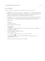
2
ROE 192.168.90.20
2
ROE 192.168.90.20
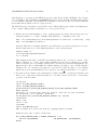
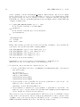
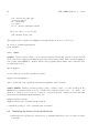
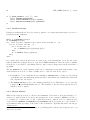
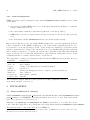
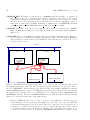
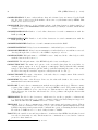
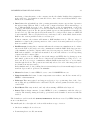
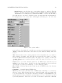
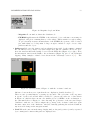
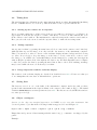
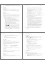
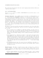
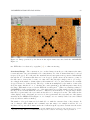
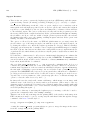
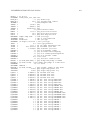
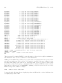
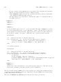
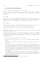
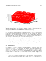
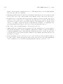
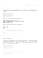
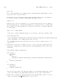
Figure 1: The ROE sends the digitized pixel data of one of the two detector chips through one and
the digitized pixel data of the other detector chip through the other fiber of a fiber pair. Each of
the two CARMENES computers may receive data from any of the ROE’s if GEIRS is configured
with the CAMPORT variable to talk to the ROE that generates the data and if the fiber that streams
the digitized data ends up at the correct OPTPCIe board configured with the DATAINPORT1 and
DATAINPORT2 variables. The two CARMENES ROE’s have the same IP address, which means they
must not be used at the same time on the same subnet.
Wherever GEIRS is run, it must be able to connect to the ROE that controls the detector
via the Internet; the fiber pair from that ROE must lead back to the expected OPTPCIe
board without swapping the two fiber heads. The fiber connection does not use any sort of
network protocol but bare 16-bit data, so it cannot work through any type of hubs, routers
or switches; it must be direct in that sense, allowing only patch panels, ST connectors etc.
to cross between laboratories. Note that the DATAINPORT1 assignments are dynamic: if any
CARMENES-AIV04B-NIR-DCS-MAN01
31
OPTPCIe board is removed from the computer, the remaining one is always addressed as
/dev/plx00.
If a spare ROE rack is available, there are two options to swap it in:
1. remove the old ROE, modify the IP address of the spare to match the default IP address
as instructed in Section A.1, put it into the network,
2. or modify the CAMPORT variable to match the new ROE’s IP address before starting
GEIRS.
Replacement of the ROE rack always requires shutting down and re-starting GEIRS.
DATAINPORT1,DATAINPORT2 Pseudo-device name used by GEIRS to “find” the incoming
stream of pixel data on the OPTPCI board. Almost always plx-00 and plx-01 unless more
than one OPTPCI board are plugged into the computer. The first (left) of the two digits enumerates the OPTPCI boards on the GEIRS worstation starting at 0. The second (the right)
of the two digits enumerates the two fibers/DMA channels, 0 or 1. (The physical layer of the
data/fiber connections from the ROE to the computer comes always with fiber pairs.) For instruments with only one fiber/DMA channel (Luci, Linc-Nirvana, and PANIC or CARMENES
with CAM NDET=1), the second (right) number is always 0, and DATAINPORT1=/dev/plx?0. For
instruments with two fiber/DMA channels (PANIC with CAM NDET=4 and CARMENES with
CAM NDET=2), DATAINPORT1=/dev/plx?0 and DATAINPORT2=/dev/plx?1. The software does
not support feeding the two fibers of one instrument into two different OPTPCI boards, so the
first (left) of the two digits of DATAINPORT1 and DATAINPORT2, represented by the question
mark above, needs to be the same.
CAMSERVERPORT IP port number of the command server. The default is 8501 if not set
otherwise. After GEIRS startup one can test with a command in the style of
nc -v -z server port
from the Unix/Linux shell whether GEIRS is actually using that port. The GEIRS server
can also be asked with get CMDIPPORT what its current port is—but this is not much useful
because to submit the get to the correct server implies that one already knows the port. . . ).
CAMSTATUSPORT IP port number of the status scanner. The startup script sets the standard
port to 8501 for PANIC and CARMENES, to 9501 for LUCI1 and LN, and to 10501 for
LUCI2.
CAMSTATUSHOST Name of the host with the status scanner.
CAMSHMSZ Shared memory (in MBytes) reserved for use by GEIRS, see Section 2.6.4. This is
roughly aligned with the total available RAM of the host computer via
setenv CAMSHMSZ ‘cat /proc/meminfo | fgrep MemTotal | awk ’{printf "%d",$2/2048}’‘
in scripts/GENERIC. The divisor is basically 1024 (to convert kilo-bytes to mega-bytes)
multiplied by some rather arbitrary small factor of the order of 1 or 2. It might be adjusted
if concurrent data acquisitions (more than one GEIRS session) are run by multiple users or
for multiple ROEs at the same time. This sets an upper limit of the number of frames and
images that can be acquired without intermediate save operations.
CAM IDSTR A string generally used in frames of GUIs.
32
NIR (GEIRS Manual) (v
2.344)
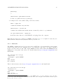
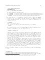
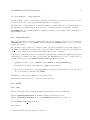
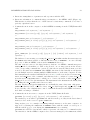
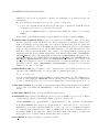
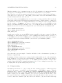
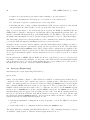
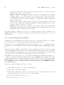
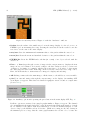
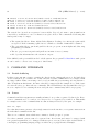
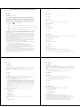
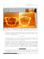
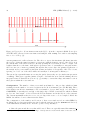
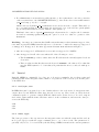
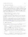
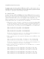
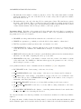
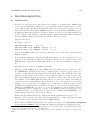
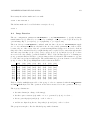
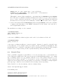
Figure 2: Illustration of the influence of the CAM DETROT90 parameter on the image. From left to
right: CAM DETROT90=0, CAM DETROT90=1, CAM DETROT90=2, and CAM DETROT90=3, each time in
conjunction with CAM DETXYFLIP=0 (pure rotations).
CAM NDET Number of infrared chips, and—with the exception of PANIC and CARMENES—
always 1. If the parameter is set to 1 for CARMENES, the GEIRS software will treat the
entire readout system as if only the SCA1 detector were present, triggering only the ADCs on
one of the two ROE boards, receiving data only through one of the two fibers, showing only
a 2048 × 2048 image and so on.
CAM ROE FWSYNC TLIMIT
CAM DETROT90 A number from 0 up to 3 (inclusive) to trigger rotations of the detector
image by a multiple of 90 degrees to the right. (The fact that these rotations are clockwise
is a consequence of GEIRS using a left-handed X11-type coordinate system acting on some
internal index tables.) Defining a value of zero is equivalent to not setting the variable at all
such that GEIRS falls back to the default of a non-rotated output. This effects both, the views
within the engineering GUI’s described in this manuscript as well as the pixel distribution in
the FITS files. The default for CARMENES is either 1 or 3 to generate a view where the two
detector chips are aligned left-right (not up-down). The design of the detector mount allows
to re-install the detector rotated by 180◦ , so whether the standard is 1 or 3 depends (i) on
the actual way of detector installation and (ii) on the various opinions of interested parties
to flip the wavelength and order axes.
The CARMENES 2-chip layout is special insofar the switch of DET ROT90 from 1 to 3 is
similar to a swap of the fiber heads (at least if the default of CAMDPORTS=2 is used). This
cannot be used for a lazy correction of a wrong fiber connection, though, because features
like the reset windowing (Section 5.6.1) operate on a dedicatedly enumerated order of the two
Hawaii chips: wrong fiber connections let the reset windows appear in the wrong corners of
the display and FITS files.
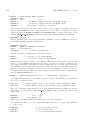
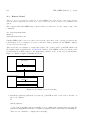
CAM DETXYFLIP If set to 1, this commands a left/right reflection of the images along the
vertical axis. If set to 2, this commands a up/down reflection of the images along the horizontal axis. If not set or set to zero, there is no flip. If set to 3, the two flips are combined
and replaced by a rotation of 180 degrees.
In combination with the previous keyword, this supports eight orientations of detector images—
the basic mean to obtain a (rough) standard image orientation along N and E in the images
(Sect. A.2). Rotations and reflections are not commutative: the rotation will be executed
first.
Note that swap of the two fibers that transport the data from the ROE rack to the GEIRS
computer (on any of the two sides) cannot be replaced or undone by any combination of the
CAM DETROT90 and/or CAM DETXYFLIP keywords.
CARMENES-AIV04B-NIR-DCS-MAN01
33
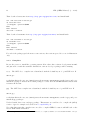
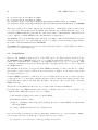
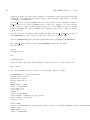
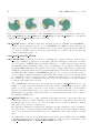
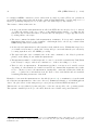
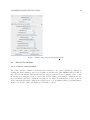
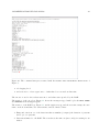
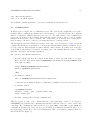
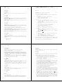
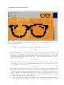
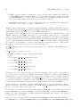
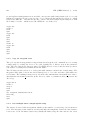
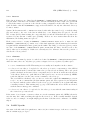
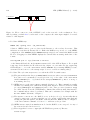
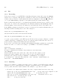
Figure 3: Left: CAM DETROT90=0 and CAM DETXYFLIP=1 (no rotation followed by right-left flip)
or CAM DETROT90=2 and CAM DETXYFLIP=2 (180◦ rotation followed by up-down flip). Second from
Left: CAM DETROT90=0 and CAM DETXYFLIP=2 (no rotation followed by up-down flip) or CAM DETROT90=2 and CAM DETXYFLIP=1 (180◦ rotation followed by right-left flip). Second from Right:
CAM DETROT90=1 and CAM DETXYFLIP=1 (90◦ followed by right-left flip) or CAM DETROT90=3 and
CAM DETXYFLIP=2 (270◦ followed by up-down flip). Right: CAM DETROT90=1 and CAM DETXYFLIP=2
(90◦ followed by up-down flip) or CAM DETROT90=3 and CAM DETXYFLIP=1 (270◦ followed by leftright flip).
CAM BEHIND DATA Switches on a certain suite of tests whether the amount of 16-bit words
received from the ROE exceeds the number expected by the number of pixels and frames.
CAMITIME MULT Read but not used anywhere.
CAMITIME PLUS Read but not used anywhere.
CAM PAT TIMING Values of 0 or 1 indicate timing analysis with old FPGA electronics (version 2 of the MPIA electronics up to and including LUCI1) or of newer electronics (version 3
and equivalent to all cameras this manual is applicable to).
CAM MAX EDTBUFSIZE Defines the size of a single buffer in the ring buffer in units of
kilobytes.
CAMDPORTS The number of PCIe channels and fibers set up for the transfer of the ADC data
from the ROE. This is 1 for all cameras with a single chip (LINC-NIRVANA and LUCI),
2 for PANIC and for CARMENES. The basic advantage of using two channels (which at
the same time implies using both fibers of the connection from the ROE to the computer) is
that the data transfer is more stable.11 If the parameter CAM NDET has been set to 1, GEIRS
silently reduces CAMDPORTS to a value ≤ 1 if this environmet variable was 2.
CAMREADPARTSZ
CAMEOFCONV Indicates a number of end-of-frame bytes generated by the ROE. Not used
nor tested (so the default is zero.)
CAMEOFERR Selects whether errors related to the CAMEOFCONV and/or CAMEOFPCHAN
flags are logged as “hard” errors plus messages on the shell or as warnings.
11
. . . related to the existance of a 128 kB FIFO on the OPTPCI at the end of each channel/fiber that feeds into the
PLX. At a standard readout frame period of 1.3 seconds, the net 16-bit data stream from the ROE to the computer
is 4 × 2 × 20482 /1.3 bytes per second, or 26 MB/sec accumulated by the 4 PANIC chips. With a single 128 kB buffer,
the maximum latency of the DMA transfer to the Linux kernel is 128 × 1024/(26 × 10242 ) sec, or 5 ms. If the data
are distributed over both channels, the effective FIFO capacity is 2 × 128 kB, and the latency allowance is doubled to
10 ms. With the 2 chips of CARMENES, the maximum latencies double to 10 or 20 ms for the counts of channels,
espectively.
34
NIR (GEIRS Manual) (v
2.344)
CAMEOFPCHAN Nonzero values indicate that end-of-frame bytes are inserted by the ROE
into the data of each port as check marks to allow some over/underrun tests by GEIRS. This
feature is not used nor tested.
CAMMODE Takes influence on the buffering scheme of the shared memory (with a number of
buffers then set by the CAMINTFBUFS environment variable). Usually not defined, which means
defaults to zero.
CAMSERIALEOL RD Number of end-of-line characters for serial communication with the
ROE (reading).
CAMSERIALEOL WR Number of end-of-line characters for serial communication with the
ROE (writing).
CAMSERIALSPEED Baud rate of serial communications with the ROE.
CAMSERIALDELAY Delay between transmission of individual bytes on serial lines.
CAMMOTSERDELAY Delay between transmission of individual bytes on serial lines connected
directly (through a line connected to the GEIRS computer) to motors.
CAMBROWSER Full path name to a HTML browser. Only used if the online help is called
with the button as in Section 5.3.
CAMWWW The full path name of the HTML help file for use as in Figure 7.
CAMAUDIOPLAY The name and options of the executable that plays the sound files, for
example paplay, aplay -d 5 -N -q, auplay or audioplay. This specifies the full command
stripped off its final parameter (the file name), such that attaching the name of the sound
file and redirecting the standard output is a valid system call. See also [9].
CAMAUDIOMIX The name of the mixer of the audio files, for example aumix. If the variable
is not set, no mixer will be used.
CAMXSERV The name of the X-server. If not set, the value will default to the content of the
DISPLAY shell environment variable.
MOTPORT Ports for direct communication with the motors (filter wheels etc.). This is a commaseparated list of values, one per MoCon board under GEIRS control. The parameter should
be left blank if GEIRS does not control motors. This means it is only relevant to PANIC,
which addresses the four filter wheels and the cold stop shutter through the first in this
address list.12
TELESCOPE The label of the observatory, which is used to set the geographic coordinates and
to convert from equatorial to topocentric coordinates. Only a few fixed strings are supported:
LBT, CA3.5m, CA2.2m, Lab, GENERIC and some obsolete others.
TEMPORT Port for direct communication with the temperature and pressure sensors. This is
only relevant as a default for the crontab job (i.e., the executable panictempress that reads
PANIC temperatures and pressures if the command line option -i is missing and if the default
IP address of CAHA is not to be used. Only relevant to PANIC.
TMOUT If the variable is set and larger than zero, it indicates that GEIRS should shut down if
it is idle for that many seconds, which means if no commands are received and no buttons
pressed for that duration.
12
At MPIA, the address is found with nslookup elotest.
CARMENES-AIV04B-NIR-DCS-MAN01
35
This list is mentioned for documentation purposes. Not all combinations of cameras and variables
are supported or meaningful. In case of doubt it is recommended not to set a variable.
These variables are set in the startup script and exported, so they are defined in the child suprocesses; they are not exported “up” to the calling operator’s shell—there is no mechanism in Unices
for such modification in the other direction.
The generic strategy in the GENERIC script is to honor (not to change) variables which are already
set when the script is called. This allows users with lesser knowlege of shell scripting to configure/set
the variables at other places, for example immediately before calling the script or in the standard
files like .bashrc or .bash login. Another use of this feature is that one can call GEIRS versions
that are older than the most recent three ones or one can invoke pattern versions that are older
than the most recent one. Here is an example in the case of LN started from a bash(1) shell:
export CAMOLD=bintrunk_r657
export CAMROE_REV=Nirvana_r97
start_nirva_old
A further aspect is that one can run GEIRS sessions in parallel on the same computer by different
Unix/Linux accounts without interference, if the communication channels from the observer tool
to the GEIRS server and from the GEIRS server to the ROE are kept separate, and if the computer
is equipped with at least as many OPTPCI boards as active (=non-simulated) ROE’s:
export CAMSERVERPORT=10501
export CAMPORT=tcp://192.168.0.14:4000
export DATAINPORT1=/dev/plx00
start_luci2_new
export CAMSERVERPORT=9501
export CAMPORT=tcp://192.168.0.24:4000
export DATAINPORT1=/dev/plx10
start_luci1_new
(Note that this is just an example. Variables will differ for the real instrument depending on
hardware configurations!)
In summary: all major parameters are equipped with defaults (which depend on the instrument).
If the defaults do not represent the current hardware configuration—because someone changed
ROE IP addresses, re-plugged fibers and so on—the GEIRS parameters should be changed either
with the Linux shell export commands as illustrated above before calling the start script or by
modifying them through the startup GUI (Section 4.2.)
3.3
Postprocessing
An infinitely rich interface to post-processing the data, starting pipelines or archival systems is
offered by the script or executable located in QueueFiles on the GEIRS computer. (The file
QueueFiles may be anywhere in the $PATH but is usually in $CAMHOME/scripts/QueueFiles.) It
is called at the very end of every save command (but not at the end of saving the intermediate
frames configured by the sfdump command). It receives two parameters, the file name of the
file created by that save command, and a number indicating the number of files expected to be
created by that save command. (The latter offers some means to postpone actions in that script
36
NIR (GEIRS Manual) (v
2.344)
for example if GEIRS constructs a series of files with one window per file.) These two parameters
are available in the script as $1 and $2 in the common Unix/Linux shells, or in the argv vector of
higher programming languages if one would replace the shell script by any binaries.
The features of that architecture are:
• At the point in time when QueueFiles is called, the FITS files are already closed. So instead
of polling the status of the crep counter or any similar status variable, or polling the file
system for any new files that arrive, it is safer and less disruptive to trigger pipeline actions
by adding them to the script.
• The save command is finished when QueueFiles terminates. If foreground commands in
QueueFiles hang, save does not terminate—which might lead to the wrong conclusion that
GEIRS hangs whereas it actually waits.
• As already said, QueueFiles is called synchronously with the save. Within this script, however, further actions may be pushed into background processes such that they are effectively
becoming asynchronous to the GEIRS processing.
• The sync and sync save command wait on the save command, so the delay depends implicitly on the timing chosen within the QueueFiles.
• The QueueFiles must be a valid script and of course be executable as usual in the Unix/Linux
sense. It may be empty—aside from comments etc.—if there is nothing to be done.
• There is only one QueueFiles. If instrument pipelines or monitors need variable actions
depending on other than the two variables forwarded as command line arguments, they either
need to edit/move/remove the QueueFiles dynamically—cautiously synchronized with the
save—, or gather more information from the shell or user environment and use standard
branching/switching statements of the shell.
Examples of actions in the QueueFiles are ds9 calls (Section 4.3.3) or examination of test files with
the script in test/QueueFiles of the source directory. Panic! uses this file to add CAHA ambient
data to the place where forthcoming save processes pick up additional FITS information.13
This interface is a specialized (by time and place of the invocation) call to the operating system.
The system command (Section 5) to the shell offers the more flexible and general interface.
13
An equivalent action for CARMENES was removed for CARMENES in r748 because this needs to be done via
a wget call on their infrared computer which turned out to introduce more jitter in the timing than accepted by the
instrument team.
CARMENES-AIV04B-NIR-DCS-MAN01
4
37
GRAPHICAL USER INTERFACE (GUI)
The software handles all infrared cameras at Calar Alto. Therefore the observer, once having used
one system, will easily feel at home with the other cameras. Changes are introduced only due to
different hardware. The aspects of GEIRS working as
1. a telescope control interface,
2. a motor control interface,
3. a temperature/pressure monitoring system
are partially disabled or virtualized in the Carmenes configuration.
4.1
Start-up (Standard)
It is useful to check with
ps -C geirs_shmmanager
whether someone else is already running GEIRS on the machine. Then the command
start carmenes [-iwin] [-gui] [-disp] [-cmd]
respectively
start carmenes old [-iwin] [-gui] [-disp] [-cmd]
or for the most recent version of the software
start carmenes new [-iwin] [-gui] [-disp] [-cmd]
starts GEIRS. If no command line option is used, all four of them are implicitly activated. If the
-iwin option was present (explicitly or implicitly), it commences with the start-up screen of Figure
4. The controls and/or the image GUI will be opened depending on the presence of the options
-gui and/or -disp. The command server is started depending on the presence of the option -cmd.
The -gui option works only if the command server is either started here or already running.
Error messages of the “Command not found” class indicate that the software may not have been
compiled, installed or simply not integrated into the PATH of the operating system.
The start commands refuse to start GEIRS if the associated TCP port is already in use.
The startup script may replace some files at common places (like in the scripts or INFO directories)
by versions that depend on the GEIRS version that just has been called. It generally does this by
managing symbolic links. The only reason for this breaking of the rules of versioning is that some
other softwares (drivers that access GEIRS from the outside) expect to find them at fixed locations
in the directories.
In the associated shell script, a set of configuration decisions have already been made. Most of the
screen shots of this manuscript show the result of setting CAMFONT to helvetica in scripts/GENERIC,
for example.
The startup script shows the remaining disk file capacity on the initial FITS file directory. The
guideline is that readout electronics, detectors and fiber channels inbound via the OPTPCI boards
38
NIR (GEIRS Manual) (v
2.344)
Figure 4: Startup screen to start GEIRS.
are not shareable resources. The number of GEIRS instances running in simulation is not limited
(apart from details mentioned elsewhere), but the number of GEIRS instances handling any real
ROE or OPTPCI board at a time must never be larger than one. To that purpose, the startup
script runs once geirs cleanup with a test flag, which detects GEIRS processes already running
by this or other users on this computer (see Section 5.5). On a system similar to LUCI with two
GEIRS instances possibly running in parallel, don’t be alarmed if some GEIRS linux processes pop
up here, because this may be the handler of the other arm of the telescope! In the standard case
of running GEIRS for PANIC, CARMENES or LN with a telescope, GEIRS processes should not
appear in the list—anything else means that either
1. local policies of properly shutting down GEIRS have not been communicated well between
observers, or
2. the previous shutdown of GEIRS did not run smoothly. In that case running geirs cleanup—
without the -t option—may be useful to clean up these residuals, before trying again to start
GEIRS.
Some parameters may be edited in Figure 4 at this time:
• Observer Enter your name as observer. This will (i) appear in the FITS files and (ii) toggle
allowances for some commands reserved for engineering purposes. (See Section 5).
• Camera This is a fixed entry here, derived from the name of the startup command.
• Camera-Optic This is fixed here, because the optical elements are not changing properties
as far as GEIRS is concerned.
• Detectors The number of detector infrared chips is fixed here.
• Detector-Output The number of channels used in parallel to shuffle the read-out data
through the ADC chain. This degree of parallelism has major influence on timing and on the
CARMENES-AIV04B-NIR-DCS-MAN01
39
interlacing of data that arrive on the computer via the fiber links. Luckily, this configuration
is also fixed here. (32 channels are announced here; data of the four additional ADC’s of the
AD36 are not transferred.)
• Data Defines through which bus of the operating system the software expects data. Operation
through as many different PCIe boards as the computer hardware allows interfacing to a
set of different ROE electronic boxes. Details depend on the slot assignment on the host
computer. The names /dev/plx-?? are used for historical reasons. They do not correspond
to UNIX/Linux devices in the file system (which appear as /dev/plx/Plx* if installed as
described above). The first placeholder in the name is 0 or larger if more than one OPTPCI
board is installed. The second placeholder is 0, and may be also 1 if the ADC data from the
ROE are also sent in parallel via the second data port.
If this is offline, the software will assume a ROE simulation mode. The two stages of
simulation of data by the pattern generators of the control electronics (without detector) are
then not available either.
• RO-Electronic Setting this to offline will start the software in a simulation mode. Otherwise it is the TCP socket and port for the communication with the ROE. If the data generator
of the OPTPCI board in the computer will be used for test purposes described in [5], but if no
ROE rack is available or if this rack is switched off, some fake address of a non-responding
computer should be inserted here.
In the simulation mode, GEIRS produces fake images and FITS files by placing spots at
randomized positions across all detector chips in the field mimicking a seeing close to one
arcsecond. It does not try to communicate with the ROE via the network or to receive image
data through the fibers. The positions are randomly selected for each of the images; they are
not drawn from any star catalog.
In the simulation mode, the pointing direction is randomly selected from zenith angles between
0 and 60 degrees and no preference in azimuths.
• Motors Irrelevant, because GEIRS does not control CARMENES motors.
• Temp.Controller Irrelevant, because temperatures are neither controlled nor monitored by
GEIRS for this instrument.
• Telescope This entry is fixed, and triggers a selection of geo-positioning data of the observatory that end up as FITS header cards and UT/ST converter parameters in the telescope
control GUI.
• Focal-Ratio This entry is fixed, and only effects writing a FITS header keyword.
• Status This is always offline, because GEIRS does not communicate with the telescope
controls. The virtual pointing and catalog operations described further down are nevertheless
enabled.
The defaults are read from the file $CAMTMP/CAMDEFAULTS which was created by GEIRS during the
most recent shutdown.
The small symbols to the right end of these fields indicate a type of action:
• Circles are multiple choice selectors
• Down-triangles are scroll-down menus
40
NIR (GEIRS Manual) (v
2.344)
• Squares are buttons that toggle binary values changing to green if activated
• Right- or left-triangles are incrementors or decrementors of an editable field
• No such symbol appears for push buttons or text entry fields.
• Asterisks announce opening of additional standalone GUIs. Presence (absence) of the asterisk
shows whether the window will be closed (opened) if the button is pressed.
After you press all Figure 4, the subsystems (most noticably the ROE) are initialized and the
GEIRS window of Figure 6 will appear. At that time all (recent) instrument patterns send commands to the ROE which switch most of the ROE’s LED’s off. The LED’s of the network card of
the ROE cannot manipulated by these software means (and must be taped to shield their light).
The button OK compares the current parameters of the command server with the parameters proposed in the GUI and skips the initialization if the two sets are the same.
Actually both the “Controls” window (Figure 6) and the main display window (Figure 15) may be
suppressed by removing the -gui and the -disp options, respectively, from the call of the shell
in the $CAMHOME/scripts/GENERIC script. These changes in the configuration are available if the
instrument is run in a stable production mode where the pipeline investigates the FITS files that
are produced, such that the quick look at the frames is not needed or replaced by the more common
ds9 viewer.
If some subsystems of GEIRS, like the ROE, the Motors or the Telescope are set or left in a not
available or offline state in Figure 4, some parts of the GUIs described in this manual display
yellow diagonal crosses to provide a visual warning that the corresponding section of the action or
information is in some state of software emulation/simulation.
4.2
Start-up (Engineering)
Alternatively there is an engineering GUI called by
geirs_start
which opens up similar to Figure 5. (The GUI is not available on systems where neither the gcj
compiler nor the Oracle Java compiler was found at compilation time.) This allows experienced
users to edit many parameters on a finer level without editing the GENERIC script, but at a higher
risk of starting GEIRS with modes that are not supported. The program scans a fixed list of
ROE IP addresses and puts those that seem to be online into the selector for the CAMPORT. It puts
subdirectories of CAMHOME that look like compiled GEIRS versions into the CAMBIN selector. If the
Continue/Start button is pressed, the program sets some of the environment variables mentioned
in Section 3; labels in the GUI and environment variables correspond to each other. Then it calls
the shell script scripts/GENERIC with the options set in the third but last line of Figure 5. The
principal rationale for having this GUI is that one can
1. mix hybrid instrument configurations as they frequently occur in the MPIA development
process.
2. swich temporarily to a configuration without editing the GENERIC script.
The major drawback of starting with this GUI is that none of the confirming messages do appear
on standard output as they do with the start* scripts mentioned above.
CARMENES-AIV04B-NIR-DCS-MAN01
41
Figure 5: Engineering startup with geirs start.
4.3
4.3.1
The GUI’s windows
Camera control window
The control window of Figure 6 is the interactive interface to the camera. Fields are changed by
clicking into them, which produces a green frame around the field. (The GEIRS GUIs are build on
the low-level X11 library. This means that any triggers by mouse-over or similar events, or size
modifications by dragging edges or corners that modern desktop environment configurations offer
are not available.) However, editing in the fields is not possible. You always have to type your text
anew, which intermediately changes the background to red, and finish editing by pressing Enter.
In the top row three pull-down menus provide further options:
42
NIR (GEIRS Manual) (v
Figure 6: The camera control window with its drop-down menus.
2.344)
CARMENES-AIV04B-NIR-DCS-MAN01
43
• File Menu
– Re-init ROElec resets the read-out electronics
– System Setup will bring up the initialization window of Figure 4.
– Help Opens a web browser which shows a HTML version of the command list, similar
to Figure 7, equivalent to the contents of Section 5.3. This will fail if the environment
Figure 7: The web browser called by the Help button in Figure 6.
variables CAMWWW and/or CAMBROWSER of Section 3.2 are not configured correctly.
– Close Controls Closes the window of Figure 6. Use this if and only if you are either
knowledgeable of how to re-open the window or never want to see it again.
– Shutdown GEIRS will close GUI’s related to the session and terminate the command
server and shared memory manager. It is equivalent to the quit command (Section 5.3).
This is a swift and recommended way of terminating GEIRS.
• Modules Menu The modules menu starts the different modules, each of which has its own
description section.
– Display: Toggles the status of the image display, Figure 15, i.e., starts it if not shown
and closes it if shown.
– Telescope Telescope control. Only available for PANIC.
– SatCheck Turns on audible saturation warning.
– TempControl Displays a graph with the pressure and various temperatures inside the
dewar This button is only present if the CAMWOTPCTRL is not set in the environment (that
is, in the shell script to start the instrument). The display is passive in the sense that
they show a scan of lines in a special format taken from a log file that is typically fed
44
NIR (GEIRS Manual) (v
2.344)
by a cron(5) job which reads the sensors . GEIRS does not need to be online to store
these. The plot may even be displayed with
cd GEIRS/INFO ; xterm -e gnuplot tmp_gp.panic
if GEIRS is not started.
Irrelevant in the case of LBT instruments or CARMENES which have dedicated subsystems to deal with these house keeping data.
– JitterPlot shows statistics of the frame arrival time jitters, Section 4.3.6.
– New InstrShell Opens a instrument shell window similar to Figure 10.
– Del. InstrShell Closes the instrument shell window.
– DebugLog-Mon. Opens a debug log monitor similar to Figure 11.
– ErrorLog-Mon. Opens an error log monitor similar to Figure 12.
– ROE-Log-Mon. Opens a log monitor similar to Figure 13 showing a history of command exchange with the ROE.
– Cmd-Log-Mon. Opens a log monitor similar to Figure 14.
• Options Menu
– Sound calls up a sound menu, where a specific sound file can be associated with a
variety of different events (such as telescope moves, completion of a read ...).
– Savepath, Macropath, and Objectpath are directories that tell GEIRS where to save
FITS data and where to look for macro and object (astronomer’s pointing coordinate)
files.
Macropath, the default search path for GEIRS macros, is usually set to the MACROS
subdirectory in $CAMHOME.
A default for the CAMPATH is proposed which is derived from the current value of the
directory by replacing the lowest component with the instrument name and an ISO
time stamp of the current date (Figure 8). Pressing cancel keeps the current value—
which is shown in the title bar of the GUI. Editing the path name and pressing ok or
carriage-return may pop up another window which asks to create the directory.
Figure 8: Popup after Selecting Options→SavePath... in the Controls GUI of Figure 6.
At the time when GEIRS is shut down, the values are stored in the files CAMPATH,
CAMMACROS and CAMOBJECTS in the $CAMTMP directory, and retrieved from there at the
next startup.
– Logfile specifies where the log file is kept.
Below the drop-down menus various fields display the status of the camera and allow the setup to
be changed:
• Read setup
CARMENES-AIV04B-NIR-DCS-MAN01
45
– Idle This parameter defines whether the transition from the idle mode to the read mode
is done
∗ abruptly (break, with a sort of immediate termination or break of the idle cycle) or
∗ whether the currently running idle cycle is completed before the read starts (wait,
reaching first a type of break point at the end of the idle cycle before switching to
the read mode).
Using break has the advantage of starting the reading with the least possible overhead,
but it usually leads to visible edge effects in the next frames because the clocking through
the detector was interrupted at some position along the “slow” direction. For this reason this parameter defaults to wait for all instruments. There is an intermediate type
called auto which is equivalent to wait for integration times shorter than some configurable threshold and to break for longer integration times. The associated command is
idlemode in Section 5.3.
– Idle Type The idle mode is the (usually periodic) pattern of voltages applied to the
detector lines (reading and resetting) while the ROE’s ADC’s are switched off such that
no data are actually transferred via the fibers to the workstation. GEIRS supports four
choices:
1. ReadWoConv (Read without conversion) Reads and resets execute the same timing
pattern as in the read mode. The cycle time of these idle cycles is the same as the
main mode, including the prolongations by any integration times; this aspect plays
a major role if the Idle button has been switched to wait.
2. Lir (Line interlaced read) A cyclic repetition of the read-reset-read pattern at the
minimum integration time (which means, the integration time implied by clocking
once through the detector at the current pixel time).
3. Rlr (Reset level read) Resets then reads the detector line by line. There is a single
read of each pixel in this idle pattern, so this is basically clocking once through the
chips in half the time relative to the Lir idle mode.
4. Reset (Reset only) Executes a series of resets.14 No reads are involved and therefore
these idle mode cycles are the quickest available.
With the exception of PANIC the default is Lir for all instruments. The idle patterns are
unaware of any of the three possible subwindow sets of the current read mode (Section
5.6.1), which means timing and resets in the idle cycles are equivalent to full frame
handling of all chips. The associated command is idlemode in Section 5.3.
– Read Mode The different read modes available are described in detail elsewhere [6].
For standard broad band observing this should normally be left at the initial default of
the instrument (which is lir for LN). The GUI sends a ctype command of Section 5 to
the command/interpreter shell.
– IT(s) is the integration time in seconds. The detector is clocked with a rate of 100 kHz,
resulting in a minimum integration time of
2048 × 2048 pixels 2 frames
×
= 2.7 sec
32 channels
100 kHz
(1)
in full-frame mode that reads two frames, this accumulates 2.7 sec like in Figure 6.
– cycT[s] is the total time for one read cycle in seconds.
– # Read / # Resets is the number of reads and resets executed in the current read
cycle.
14
full frame or line by line, I cannot tell. . . RJM 2015-08-03
46
NIR (GEIRS Manual) (v
2.344)
– ieff(elapse time) gives the observing efficiency as the ratio of integration time to cycle
period.
– seff(elapse time) gives the system efficiency as the ratio of time for read-out to elapse
time.
– Repeat is the number of images N with the specified exposure time T which will be
taken each time a read is executed (read-cycle). The total exposure time will then be
N × T seconds. The maximum number of images depends on the computer shared
memory set up in Section 2.5 and the setting of CAMSHMSZ in scripts/GENERIC. The
current sequence number of the reads is displayed to the left (Read button, see below).
Endless may be pressed to start an endless loop of reads. The images are read out
with the current integration time and dumped to the display. They are not saved unless
the autosave option has been activated via the GUI (Figure 9) or autosave command
(Section 5.3). This is useful for positioning the telescope before e.g. starting a macro.
– Read The read button executes a read using the current exposure time and number
of repeats. On completion of a read, the images are not saved unless autosave is
selected under the save option. While the ROE is reset—for example explicitly with the
Re-init ROElec menue or implicitly while a new srre pattern is uploaded—the label
on the button changes from Read to R:. The button is disabled while an exposure is
executed.
– Save The save button saves the most recent image(s) obtained using the currently
defined save options.
– Filename The name of the next file to be saved by pressing the Save button at the
beginning of this line or by issuing a save-command from a script. One can either specify
a name or a root. In the latter case the filename is the root plus a four digit integer,
which will be automatically increment by one each time a save is executed. By specifying
the root, the system looks for the highest free filename. If a filename ends with a number
this number will be increased.
– Save-Options Calls up a save configuration panel, Figure 9, which defines the default
way in which to save images. The file name to be created next is defaulted. The range
of frames to be saved follows in the next line of options. The area is the data section in
pixels, in 1-based FITS coordinates—equivalent to having defined one software window.
The main choices are whether
∗ to save individual exposures as separate disk files, equivalent not to activating any
of the push buttons;
∗ integrated to integrate them (add them up arithmetically) and save only a single
image;
∗ FITS-cube to store the individual frames as layers following the 3-dimensional
FITS cube standard;
∗ MEF to add the -M option to the save command and end up with the multiextension FITS format, were images and subwindows are stored as FITS extensions,
one extension per window
∗ FITS compr. to use the “internal” tile compression registered as a convention of
the FITS standard [10, 11].
∗ dif-intf No longer supported.
∗ sngle frms to add the -S option to the save command, which puts the individual
frames into the FITS files, not the pre-correlated/preprocessed images.
∗ auto-save to save the data automatically (without waiting for a request through a
save via command shell or GUI)
CARMENES-AIV04B-NIR-DCS-MAN01
47
∗ immed.-save to save the data as soon as reading a frame is completed. (The difference to the auto-save is not waiting for macro termination and even starting the
disk transfer before saving the previous frame has finished—used for the dif-intf.)
Note that the save options are overridden by any options specified in observing macros.
For example save -f 2 -i in a macro will integrate from image 2 to the end of the
Figure 9: Save options window
series, and save only a single file, even if the save options specify saving images separately.
Turning on auto-save will execute a save after every read, without clicking on the save
button.
– Test indicates that not the current parameter of the Filename is the root name for
the next image, but simply test. After the test exposure the previous file / root name
is restored (unless Test is activated again). The purpose is to separate one-time test
exposures and a stream of regular exposures easily by file name in the directory of the
operating system.
– Object is the object name which is written into the FITS header under the keyword
OBJECT for the current image. It will be updated automatically if object selection is
done through object files (recommended), or can be changed by hand.
– Sky Clicking on the sky button writes a sky flag into the FITS header, but otherwise
has no effect.
– Comment to be included in the FITS-header.
– Macro Specifies a macro (file with a list of GEIRS shell commands) to be executed by
the macro parser. If the filename has the (recommended) suffix .mac, the filename may
be specified without the .mac extension. The macro file must be in the MACROS directory
specified under the macro path in the options menu (see above) or otherwise be specified
by the full path name. Please refer to Section 5 for the macro syntax and commands.
48
NIR (GEIRS Manual) (v
2.344)
Specification of the macro just provides the file name; the macro is not started yet but
with the button right to the entry field.
– Execute, Pause, and Abort control the execution of observing macros, reads and
running programs. Note, that if a pause or abort is issued, the macro will continue
executing until the current command is completed! Check in the command window to
be sure that the pause is in effect. Clicking on continue will continue executing the
macro after the pause.
While the macro runs, the Execute button turns yellow with an indication of how many
percent of the command lines (including debris like comments, blank lines and so on) in
the macro file have already been executed.
– Disk The green portion of the bar indicates the fraction of the selected disk which is
still available. The GUI issues an audible warning when the disk is getting close to full
(assuming you have not turned off the sounds!).
If the GUI of Figure 6 disappeared, it can be reconstructed with the control command to the
GEIRS shell (Section 5) or using the equivalent forwarding with cmd* or snd* (Section 3.1) from
the Linux shell.
4.3.2
Command Shell and Log Monitors
The Modules→New InstrShell menu starts the interactive command shell interpreter of Figure
10. The window can be closed with the Modules→Del InstrShell button.
The appearance of the Command Shell and logging windows (sizes, colors,. . . ) is defaulted as for Xterminals as set at the standard places in the file system, $HOME.Xdefaults, $HOME/app-defaults
etc.
After the prompt, the GEIRS command shell expects commands from the list reproduced in Section
5, and the terminal echos the responses. The commands send from this window and the commands
created by pushing buttons in Figure 6 are received by the same command manager and effect only
one single set of state variables. Both channels may be used at the same time.
Four additional log monitors may be opened with the Modules menu, illustrated in Figures 11–
14. These are passive displays: they filter lines from the $CAMHOME/log/*.log files; the logging
parameters and amount of information that is stored in these files does not depend on whether the
associated GUI is open or not. (The logging information does depend on the LOG LEVEL definition
in the GNUmakefile while compiling and further on the adjustments by any log commands send
to the GEIRS shell.)
The monitor of the debugging logs, Figure 11, shows
• a time stamp (local time zone of the operating system),
• the user name on the host machine,
• a (failed, due to the failure of SVN to report a version of the software if the SVN repositories
are migrated) attempt to show a source code revision number,
• the file and line number in the source code,
• the function in the source code,
CARMENES-AIV04B-NIR-DCS-MAN01
49
Figure 10: The command interpreter started with the Module→New Instrument Shell menu of
Figure 6.
• a debugging level,
• and some more or less cryptic trace of what has been executed at that time.
The arrows -> and <- show what was sent to and what was responded by the ROE.
The monitor of the error logs, Figure 12, shows the messages tagged with log levels FATAL, ERROR
and WARNING in the debug*.log file.
The monitor of the ROE logs, Figure 13, tracks log/roe*.log, and shows a time stamp, the user
name on the host machine, the camera name, and two kinds of lines:
1. Entry and exit from one of the functions that accumulate (compute) the duration of patterns
and loops over patterns,
2. Patterns submitted to the ROE. The tout shows the timeout (in seconds) for waiting for an
answer.
50
NIR (GEIRS Manual) (v
2.344)
Figure 11: The logging monitor opened with the Module→DebugLog-Mon menu of Figure 6. Another
logfile is opened at UTC midnight, so one needs to close and reopen this GUI after midnight.
Figure 12: The monitor opened with the Module→ErrorLog-Mon menu of Figure 6. Another logfile
is opened at UTC midnight, so one needs to close and reopen this GUI after midnight.
The monitor of the command logs, Figure 14, tracks log/cmd*.log. The inter flags that the line
was generated by a shell script assembled by the command shell with sh -c, and the following i,
c or s means the caller was the interactive gui, a command, or the shell, respectively.
4.3.3
Real-time Display
The display tool, Figure 15 works similar to ds9 or fv tools with some display options and similar statistics. The GEIRS display, however, is completely unaware of world coordinate systems
standards.
The main difference against saving the image as a FITS file and then calling these standard displays
is that one can address any picture in the current memory buffer rather quickly by its index. It
is also easier to navigate through pictures if windowing was used, because GEIRS has no means
to glue a set of subwindows. (geirs2Panic has been written to merge these frames after they have
been stored as FITS files.)
xpa is compiled for example by installing the heatools (Section A.6.4). If xpa available, users can
send a duplicate of each new FITS file that is generated by the save command to an online ds9
application by adding two lines like
Xpaset=‘type xpaset | awk ’{print $3}’‘
cat $1 | $Xpaset ds9 fits
CARMENES-AIV04B-NIR-DCS-MAN01
51
Figure 13: The monitor opened with the Module→RoeLog-Mon menu of Figure 6. Another logfile
is opened at UTC midnight, so one needs to close and reopen this GUI after midnight.
Figure 14: The monitor opened with the Module→CmdLog-Mon menu of Figure 6. Another logfile
is opened at UTC midnight, so one needs to close and reopen this GUI after midnight.
to the QueueFiles shell script (Sec. 3.3). As an alternative to using the type command one may
use the full path of xpaset or make sure by symbolic links that the path contains the executable.
Note that ds9 sometimes needs to read ds9-64 depending on how this was compiled. With that
setup, opening the GUI in Figure 15 may be superfluous.
52
NIR (GEIRS Manual) (v
2.344)
Figure 15: Current Exposure Display. In this example, an image/frame taken from a readout
electronics with open (disconnected) inputs is shown. A single-frame-read mode was chosen to
enhance the visibility of the stripes of the two detector’s channels.
CARMENES-AIV04B-NIR-DCS-MAN01
53
The display tool of Figure 15 shows one frame of the current set of data.
Contrast and offset of the brightness on the screen may be changed by clicking the right mouse
button. The contrast of the new display depends on how far up/down the cursor is in the image
when clicked, and the offset depends on how far to the left or right it is. This modifies the slope and
interception of the function which maps the pixel values, ADU’s, to the brightness. An indication
which color/appearance is equivalent to which pixel value is given by the long color bar right from
the main image, which stretches from the Min-Cut field up to the Max-Cut field. The display uses
a linear map for the translation of ADU’s to brightness by default (i.e., after GEIRS has been
started). A γ-correction with a power law scaling is available by setting the DISP GAMMA value
of the shared memory database to some different value in the range 0 ≤ γ ≤ 100 with the put
command (Section 5.3), for example
put DISP_GAMMA 1.4
The default after GEIRS startup is γ = 1.
The magnified subwindow in the upper right corner is selected by clicking with the left mouse
button at some place in the main window, then moving around with the four arrow (cursor) keys.
So a pre-selection of the region seen in the magnifier window happens with a left mouse click in the
main window, and a finer selection may follow by either left mouse clicks in the magnifier window
or with the arrow keys.
Zooming the main window is done by pressing the minus key (or the minus-key in the auxiliary
keypad or one of the the page-up keys in the auxiliary keypad, or CTRL left mouse button to the
same effect) or the plus key (or the plus-key in the auxiliary keypad or one of the the page-down
keys in the auxiliary keypad, or the equal key, or CTRL plus right mous button to the same effect).
The minus key zooms out and the plus key zooms in. The current region covered by the main
display is indicated by a green square in the auxiliary overview window (which displays a yellow
cross to indicate the current cursor position). The auto-zoom button turns from green to gray
while only a portion of the full detector area is in the main window.
Moving (translating) the region in the main window may be done by click-holding the left mouse
button in the overview window and moving the cursor. Alternatively, CTRL or shift combined
with middle-mouse clicks in the main window moves the region in a direction and with a stride
depending on where the cursor is relative to the center of the main window. The green rectangle
in the overview window indicates the current region visible in the main window.
Clicking on the AZ (autozoom) button is the quickest way to re-center and re-scale the main window
to the full detector region.
Some on-line data processing techniques are available. These techniques affect only the displayed
data, not the raw data saved to disk. In addition there are various helpful options to move the
telescope virtually to certain positions.
• File Menu selects the basic display size:
– 256 changes display window to 256 × 256 screen pixels. The full image is displayed,
binned 8 × 8. Note that in general you will not see your objects in highly binned mode
as they most often will happen to fall between the displayed pixels!
– 512 changes display window to 512 × 512 screen pixels.
– 1024 changes display window to 1024 × 1024 screen pixels.
54
NIR (GEIRS Manual) (v
2.344)
Figure 16: File dropdown Menu
– 2048 changes display window to 2048 × 2048 screen pixels. The display will not fit onto
your monitor screen in this case!
– Display Opens a second display window with a pixel size of 1024 × 1024 in an independent screen.
– Close Closes the window. It can be restarted by selecting display under the module
menu of the camera control window or by the display command (Section 5.3).
• Color Menu selects the colour look-up table for displaying images.
Figure 17: Color dropdown Menu
– gray is a black-and-white colour look-up table.
– temp is the standard “temperature” colour table.
– bb is the standard blackbody colour table.
• MagMode Menu switches between the zoom window and a measurement of the image seeing.
CARMENES-AIV04B-NIR-DCS-MAN01
55
Figure 18: Magnifier dropdown Menu
– Magnifier Zoom window, this is the default mode.
– FWHM-Log Measures the FWHM of the indicated object each time a new image is
displayed, and plots a running history of the values. This is useful for rough focusing.
To get reasonably accurate measurements of the FWHM, the aperture of the box used
(set with radius, see below) must be large enough to include a couple of rows of sky
pixels around the object.
• SubArrays Relocates the frames read as subwindows specified by the subwin command
into the full detector geometry on a black background. The two available choices are (i) to
show the windows that will actually be stored in the FITS files (Figure 19) or (ii) to show
the information sent from the ROE to the workstation (Figure 20) prior to the additional
clipping. Many examples of this look are shown in the “Subarrays” section of [12]. The
Figure 19: Subarray menu of Figure 15 with the “software” windows.
difference between these sets of pixels in the two displays is detailed elsewhere [5].
There is some potential impact on setting up exposures: The cycle time of the exposures
is “spent” by the read-out and ADC conversion to generate the wider set of data shown
in Figure 20, which is then cut into the smaller pieces by GEIRS on the workstation to
the customized slices of Figure 19. Once knowing the geometries of the associated larger
“hardware” windows, one could reconfigure the geometry of the “software” windows to span
the same, entire area of the “hardware” windows, basically gathering the wider field without
any noticeable change in the integration time!
• Pixel When the cursor is in the image display window, the pixel position (x and y seperated
by a comma) and counts at that pixel are displayed here.
56
NIR (GEIRS Manual) (v
2.344)
Figure 20: Subarray menu of Figure 15 with the “hardware” windows.
• Radius Sets the radius of the small cursor box in the image display. See the above note on
FWHM-log about measuring the seeing. Pressing the cuts button lets the result become the
new choice for the cuts of the entire display.
• min/max Show the minimum and maximum values of the pixels within the cursor box.
• mean/dev Shows the mean and standard deviation of the pixels within the cursor box.
• FWHM/flx Shows the FWHM and total flux (in counts) of an object selected with the
cursor box.
• First - + Last Steps through a series of images in the current memory: displays the first
image, moves one backward, one forward or skips to the last. Unless you need to review a set
of images to determine, for example, whether the seeing was good enough to bother saving
the data, just leave this on last. If the Img: in the lower left corner is not set to Img: but to
Frm:, the GUI switches to frames instead of images for display and indexing.
• AZ Clicking on AZ rescales the main image to fill the frame, so the full detector area is visible.
• plot Plots cuts and surfaces through the current image on the display. An auxiliary GUI
as in Figure 21 appears. This button is disabled if gnuplot was not found at compile time
(Section 2.1.5).
Figure 21: Auxiliary options after pressing the plot button in the main display GUI, Fig. 15.
If all five options are activated, five gnuplot graphs similar to Figure 22 appear. The channel
plot is initially 128 thousand pixels wide on the horizontal axis, which is the number of pixels
in one channel for the 2048 × 2048 array distributed over the 32 channels assigned to each
detector chip by the MPIA readout electronics. (Without zooming in, the line density in
the Channel plot is so large that the entire graph assumes the red line color, because the
CARMENES-AIV04B-NIR-DCS-MAN01
57
y-axis scale is taken from the current cuts of the main display. This may be changed with
the autoscale options in Figure 21.) The channel is selected by the current position of the
cursor.
• hist Pushing this button creates a histogram of pixel statistics for the currently selected
frame or image. This button is disabled if gnuplot was not found at compile time (Section
2.1.5). First a temporary FITS file is created on disk. Then an auxiliary GUI appears which
allows to select primarily the coordinates of a rectangle in pixel units over the detectors and
cuts in ADU units. If the continue button in this auxiliary GUI is pressed, the histogram is
shown by calling the fitsImg2Asc program in the extern subdirectory.
Figure 22: Plots derived from the Display GUI after OK in Figure 21.
• RefPix There is a button above the BAD button only visible for instruments with Hawaii2RG chip, and therefore not seen in Figure 15. This offers three states: RefPix, AllPix and
SciPix. The area of 2048 × 2048 pixels of each chip is dissected into the frame 4 reference
pixels wide along each edge, and the interior 2040 × 2040 data pixels that are the relevant
data from the astronomer’s point of view. The button offers to put a mask over either the
reference or the scientifically useful pixels or to show the union of both sets of pixels at the
same time.
• BAD Toggles between displaying the bad pixels (in red) or not. Note that the bad pixels
58
NIR (GEIRS Manual) (v
2.344)
are ignored when determining display cuts only if the bad pixels are turned on. The badpixel mask is a text file stored in $CAMINFO/badpixels.instru, where CAMINFO typically equals
$CAMHOME/INFO, and the instru is nirvana, or carmenes or panic or luci2. The file contains
a list of x and y specifications in the IRAF convention. Each line starts either with the x
and y coordinate of a bad pixel or with the start-x, end-x, start-y and end-y coordinates
of a rectangle of bad pixels. The coordinate pair or quadruple is separated by white space.
Each coordinate is 1-based (as in FITS) and ranges from 1 up to the detector size (2048 for
instruments with a single 2k × 2k chip, 4096 for PANIC). Coordinates that fall outside the
two dimensions of the detector are clipped and effectively ignored. Lines in the file that start
with less than two numbers are skipped.
(The program fitsImg2Asc in geirs2Panic offers an option -b to convert a FITS image into
that ASCII format based on two-sided clipping of the histogram.)
• Cuts Display stretch control, Figure 23. This button brings up a menu with various options
for determining the minimum and maximum display levels. The options include:
Figure 23: Cuts dropdown Menu
– Cuts Allows you to enter your own minimum and maximum display levels in the ”MinCut” and ”MaxCut” windows.
– 67% Sets the display range to cover 67% of the full dynamic range of the data.
– 90% Sets the display range to cover 90% of the full dynamic range of the data.
– med3 Sets the display from (mean - 3σ) to (mean + 3σ).
– med5 Sets the display from (mean - 5σ) to (mean + 5σ).
– 3/10 Sets the display from (mean - 3σ) to (mean + 10σ).
– minmax Sets the display range to cover the full dynamic range of the data.
• Min-Cut and Max-Cut: These windows show the current minimum and maximum levels
used for the display. They will automatically update each time a new image is displayed
except if using the ”Cuts” option.
• Single/R-Sum/R-Ave/TotSum/TotAve, Figure 24. Single will display each individual
read as it comes off the camera. R-sum Adds as many images as implied by the integer
parameter of the auxiliary entry with a boxcar selection of the range. If the integer parameter
equals 1, this is effectively the same as Single. (This type of sliding average is used in financial
markets to smooth data without loosing trends. . . ). TotSum will display the sum of all images
CARMENES-AIV04B-NIR-DCS-MAN01
59
Figure 24: Frame integration dropdown Menu
taken in the current series. TotAve displays the average of all images taken in the current
series. (The sky frame, if one is active, is subtracted off these summation procedures and the
cuts applied thereafter.)
All these actions are virtual for all telescopes outside CAHA and basically irrelevant to
NIRVANA operations.
• Movie Plays a movie of the series of exposures currently in memory.
• Img shows which image in a series of repeated exposures is currently being displayed. One
may select in the pop-up menu a more precise meaning: whether the display shows the frames
enumerated as received by the ROE, or whether the images are shown, which in double- or
multi-correlated modes are differential versions of multiple frames. There is also a Dynamic
option which lets the display show the frames at the start of an exposure but switch to the
images after a time defined by the time difference between the arrival of the frames.
• Sky The sky button (small square) tells the computer to subtract a sky frame from the
images before displaying, and is on when the square appears green. The file used for the sky
frame is specified by entering a name (with the .fits suffix) in the window to the left of
the button. The menu that pops up if one clicks with the left mouse button into the field
proposes in addition two images that are not (yet) on disk but a previous frame in memory.
(One of the options is to mark the current image as the reference for subtractions in the
future, the other is to subtract the image immediately preceeding the current one.) This sky
subtraction also effects the pixel values displayed in the upper part of the window. Be aware
of this when checking count levels / saturation of a displayed image!
4.3.4
Telescope control window
Section 4.3.4 has no relevance to instruments besides PANIC.
Virtual control of the telescope, such as moving to an absolute position or offsetting from the
current position, is done on the telescope control panel. The basic information from the telescope,
such as airmass, UT, and current telescope position is also displayed here. This GUI panel should
start automatically when the GUI is first initialized. If not, you can call it up from the camera
control window (Fig. 6) in the menu Modules→Telescope.
60
NIR (GEIRS Manual) (v
2.344)
Figure 25: Telescope control window
GEIRS keeps some basic set of telescope parameters for the displays and for inclusion in FITS header
keywords. This set of values is not necessarily up-to-date, because GEIRS reads the parameters
from the EPICS interface only if it itself has forwarded one of the telescope commands and if
that action terminated successfully. GEIRS does not poll telescope parameters, which means any
change of pointing coordinates or focus offset and so on by any commands that bypass GEIRS will
not be reflected correctly in GEIRS GUI’s or FITS files up to the next telescope command.
File Menu:
• Airmass: Graphical display of the current airmass and plot of the airmass history for the
currently set object, Section 4.3.5.
• Close: Closes the telescope control panel of Figure 25. This window can be restarted from the
modules menu on the camera control panel, Figure 6, or by the telegui command (Section
5.3).
Moving to an absolute position An absolute position can be entered directly in the RA and
Dec windows. After setting the equinox, the position can be sent to the telescope by clicking on
the move button. The RA and Dec windows also display the current telescope position after each
offset.
Relative offsets Offsets in arcseconds can be supplied in the dx and dy windows. Clicking on
one of the directional buttons in the compass panel will then offset the telescope by the requested
amount. The set zero button zeroes the cumulative offsets (S(dx) and S(dy)), and the 0,0 button
in the centre of the compass returns the telescope to this defined zero position.
CARMENES-AIV04B-NIR-DCS-MAN01
61
Focus The number after the df/mm defines a step size (in mm) for focus changes. Pressing the +
or - buttons changes the focus by one step size unit with the selected sign. The Set focus button
changes the absolute focus to the value between the - and + buttons (again in units of mm).
Object Files An object file can be given in the Object-List window (the .object extension
is not needed, although the file must have it). The search path for this file—usually ending
GEIRS/OBJECTS—may be set in the OPTIONS→ObjectPath... menu of Figure 6. Objects can
be selected with a single click, and set with the set button. Setting an object sends the object’s
coordinates to the RA and Dec windows. These can then be sent to the telescope computer by
clicking on move as described above. A useful feature is that when an object is set, the airmass
panel will display the object’s current airmass in graphical form, though there is no obligation to
actually move to the object. See also Section 4.6 for a description of the format of such an object
catalogue.
4.3.5
Air Mass Window
Section 4.3.5 is only relevant to PANIC, not to any other instrument. The airmass window, Figure
26, graphically displays the airmass of the currently selected object (red dot), as well as a tracing
of the airmass over several hours of time (blue line). The number of hours depends on the width
of the window. This feature is particularly useful when used in conjunction with object files. This
feature is only useful when used in conjunction with object files or in simulation, because GEIRS
has no information on the actual telescope pointing for this instrument. Objects selected and
set from an object file will show their current airmass in the airmass window. The airmass plot
will automatically reset to the current telescope position whenever the GUI queries the telescope
computer for the current position (for example, when a read command is finished). The airmass
window can be turned off by reselecting the Airmass option in the file menu of the telescope control
panel, Figure 25. Using the quit option in the xwindows menu will also close the telescope control
panel!
Figure 26: Airmass over time window
62
4.3.6
NIR (GEIRS Manual) (v
2.344)
Time Jitter Windows
If the software had been compiled with JITTER TEST defined at two places, and if the data are read
via the PLX device —that is, not in simulation mode—, the times of arrival of data packes of a
read are logged, and the differences between these times may be displayed by opening the windows
in Figure 27 and 28 by the JitterPlot menu of Figure 6.
Figure 27: Jitter Statistics Summary
Figure 28: Jitter Statistics Gnuplot Window
The spread of these differences is a rough view on the host computer’s system load and responsiveness, and not useful information to astronomers. To gather good statistics in the usual sense,
the number of repetitions (in Figure 6 for example or set by the command interpreter) of the read
needs to be at least some tens.
An overview of the jitter data is kept in tmp/jitter*.log.
CARMENES-AIV04B-NIR-DCS-MAN01
4.4
63
Taking data
The windows introduced thus far are the environment in which one takes data manually (including
the use of GEIRS macros, see Section 5). This is useful for tests or special calibrations.
4.4.1
Setting up the camera for an exposure
Before you start, make sure you have selected the proper paths for your data etc., see Figure 6 at
upper right. You should also set the root name of the files to be stored on disk, which is also done
in the camera control window. The instrument is completely setup in the camera control window.
Here you select the read-out mode and the exposure times, to name the most important.
4.4.2
Taking exposures
An exposure is taken by pressing the Read button (below centre in the camera control window).
Although this exposes the image, it is only read into the memory of the instrument computer.
There you can use it to take a look at it on the real-time display, measure background level, seeing
etc. there. If you decide to keep the image, you also have to decide on the mode on how to save
the data (e.g. as a FITS cube, individual images, stacked images) by opening the Save-Options
window (Figure 9) with a click of the right mouse button onto the Save-Options button of Figure
6. Once set you save the data by pressing the Save button. Due to the double buffering, an image
may be saved while the next one is already been taken.
4.4.3
Image inspection with the real-time display
The features of the real-time display are described in detail in Section 4.3.3. Please note that you
do not manipulate the raw data on disk with these operations.
4.5
Saving data
The data are stored on one of the disks of the instrument computer under the path you have
specified under SavePath in the Options Menu of the camera control window, Fig. 6. The initial
default is $HOME/DATA set at start-up time in Section 4.1. The files are stored as FITS files and are
not write protected (!).
4.6
Object catalogues
Section 4.6 has only some marginal importance for PANIC, not for any other instrument. An
observer’s private object list in the following format is supported for use in Figure 25:
Object name | Alpha | Delta | Equinox | pm.A | pm.D | mag | Comment
Empty lines and portions of lines starting with the semicolon (;)—comments—are skipped by the
parser.
Example:
64
NIR (GEIRS Manual) (v
2.344)
HD 225023| 0:00:11.8| 35:32:14.0|1950|0.0000|-0.004|6.96|J=7.97
G158-27| 0:04:12.0|-7:47:54.0|1950|-0.056|-1.85|7.43|J=9.31
HD 1160| 0:13:23.1| 3:58:24.0|1950|0.006|-0.013|7.04|J=7.06
HD 3029| 0:31:02.3| 20:09:30.0|1950|-0.0001|0.011|7.09|J=7.25
Gl 105.5| 2:38:07.6| 0:58:57.0|1950|*|*|*|*
HD 18881| 3:00:20.5| 38:12:53.0|1950|0.0001|-0.030|7.14|J=7.12
The vertical bar | is used as a separator between fields. If you don’t want to put in numbers in
some fields, you still have to use a * character as a place holder. The comment field following the
final separator may be empty.
• The required fields are: Name, Alpha, Delta, Equinox. Leading J’s or B’s in the equinox field
are ignored. If the remaining equinox is not a number, a default of 2000 will be assumed.
• The optional fields are: pm.A and pm.D for the two proper motions in alpha and delta, mag
(magnitude), Comment
• The two proper motions pm.A and pm.D are in units of arcsec/century.
• All object list files must have the extension .object
If the 2MASS catalog is available in the local file system, the program TwoMassCnvrt with option
-G can be used to convert a set of targets to this format.
5
5.1
COMMAND INTERFACE
Double buffering
It takes a some amount of time to transfer the data from the camera and save it to the hard-drive
on the workstation. To reclaim some of this otherwise lost time, GEIRS has been configured with
two image buffers. Thus, a new image can be read out while the previous image is being written to
disk. To implement this feature, the macros should be written as in the example above, with a sync
tele after the telescope offset and save commands. The GUI will then only wait until the telescope
move is completed before starting the next read (the save command may still be in progress).
5.2
Parser
Commands and their arguments are usually submitted one per line, separated by line feeds. If two
or more commands are to be send at once, they need to be separated by a semicolon. This makes
for example sense for the commands that are almost always followed by the sync, for example:
save -M ; sync
Note that this format generates only a single answer from the interface, not separate answers from
the individual commands in the list.
There is one command, save, which uses commas to bundle groups of options.
Note that command options cannot be sequeezed into short forms and cannot be swapped with
non-optional arguments nor be clumpped without spaces, as some Unices allow in their shells or
some higher programming languages support with some getopt(3) libraries. Example:
CARMENES-AIV04B-NIR-DCS-MAN01
65
save -zC # wrong syntax !
save -z -C # valid syntax
As a guideline, trailing arguments or options in commands are silently ignored.
5.3
Command List
In this section a complete list of commands is given. The order is lexicographically, not by functionality. These commands and syntax can be used in macros or typed directly into the command
window or submitted with the interfaces of Section 3.1. Use with caution some commands are
better left out of macros! For example, quit will exit a macro at the point it occurs, no further
instructions in the macro will be executed. Also, if interactive is on, and ls, dir, or history are
used in a macro, the macro could stop executing and wait for a carriage return.
The subsequent pages are a PDF reproduction of the “help” page generated by texinfo in various
formats. The intend is to demonstrate to reviewers that this information is indeed available, not to
provide a reference that is anyway accessible with the online software. [For this reason, four pages
of the PDF document have been packed on a single page of the manual; this also helps to realize
that they carry their own internal pagination.]
The options to read this informations are:
1. the File→Help button in the controls menu, Figure 6, if the full path name of a browser
has been set in environment variable CAMBROWSER in the startup file scripts/GENERIC. This
is the same as calling
setenv CAMBIN=${CAMHOME}/<branch>/share
firefox ${CAMBIN}/camera.html
offline.
2. the info(1) command
info -f $CAMHOME/<branch>/share/info/camera.info
opening the screen similar to Figure 29. This may be simplified as described in Section 2.6.7.
3. as a PDF document
cd $CAMHOME/<branch>
texi2dvi --clean --pdf --expand camera.texi
evince camera.pdf
4. the help command entered in the command shell.
This is a generic account of the command interface, and again many of these do not apply to
CARMENES, in particular the commands that interface with the telescope or motor and other
controllers. The commands are either in the category type:USER or type:ENG or type:SUPER; the
commands in the latter two categories are rejected unless one is using the instrument under one of
the engineering observer ID’s or the observer ID master. (The observer ID is configured in the top
field in the GUI of Figure 4.)
66
NIR (GEIRS Manual) (v
2.344)
Table of Contents
Overview . . . . . . . . . . . . . . . . . . . . . . . . . . . . . . . . . . . . . . . . . . . . 1
GEIRS
Command Interface
Generic Infrared Detector Software
Max-Planck Institute of Astronomy, Heidelberg 8 December 2015
Richard J. Mathar [email protected], Clemens Storz
1
abort . . . . . . . . . . . . . . . . . . . . . . . . . . . . . . . . . . . . . . . . . . . . . 1
2
alarm . . . . . . . . . . . . . . . . . . . . . . . . . . . . . . . . . . . . . . . . . . . . 2
3
aperture . . . . . . . . . . . . . . . . . . . . . . . . . . . . . . . . . . . . . . . . . 2
4
autosave . . . . . . . . . . . . . . . . . . . . . . . . . . . . . . . . . . . . . . . . . 2
5
bias . . . . . . . . . . . . . . . . . . . . . . . . . . . . . . . . . . . . . . . . . . . . . . 3
6
cd . . . . . . . . . . . . . . . . . . . . . . . . . . . . . . . . . . . . . . . . . . . . . . . . 3
7
clobber . . . . . . . . . . . . . . . . . . . . . . . . . . . . . . . . . . . . . . . . . . 4
8
continue . . . . . . . . . . . . . . . . . . . . . . . . . . . . . . . . . . . . . . . . . 4
9
control . . . . . . . . . . . . . . . . . . . . . . . . . . . . . . . . . . . . . . . . . . . 4
10
counter . . . . . . . . . . . . . . . . . . . . . . . . . . . . . . . . . . . . . . . . . 5
11
crep . . . . . . . . . . . . . . . . . . . . . . . . . . . . . . . . . . . . . . . . . . . . . 5
12
ctime . . . . . . . . . . . . . . . . . . . . . . . . . . . . . . . . . . . . . . . . . . . 6
13
ctype . . . . . . . . . . . . . . . . . . . . . . . . . . . . . . . . . . . . . . . . . . . 6
14
define . . . . . . . . . . . . . . . . . . . . . . . . . . . . . . . . . . . . . . . . . . . 8
15
delay . . . . . . . . . . . . . . . . . . . . . . . . . . . . . . . . . . . . . . . . . . . . 8
16
dir . . . . . . . . . . . . . . . . . . . . . . . . . . . . . . . . . . . . . . . . . . . . . . 8
17
display . . . . . . . . . . . . . . . . . . . . . . . . . . . . . . . . . . . . . . . . . . 9
18
engstatus . . . . . . . . . . . . . . . . . . . . . . . . . . . . . . . . . . . . . . . 9
35
load . . . . . . . . . . . . . . . . . . . . . . . . . . . . . . . . . . . . . . . . . . . 17
19
engwindow . . . . . . . . . . . . . . . . . . . . . . . . . . . . . . . . . . . . 10
36
log . . . . . . . . . . . . . . . . . . . . . . . . . . . . . . . . . . . . . . . . . . . . . 18
20
exit . . . . . . . . . . . . . . . . . . . . . . . . . . . . . . . . . . . . . . . . . . . . 10
37
ls . . . . . . . . . . . . . . . . . . . . . . . . . . . . . . . . . . . . . . . . . . . . . . 20
21
filter . . . . . . . . . . . . . . . . . . . . . . . . . . . . . . . . . . . . . . . . . . . 10
38
macro . . . . . . . . . . . . . . . . . . . . . . . . . . . . . . . . . . . . . . . . . 20
22
fits . . . . . . . . . . . . . . . . . . . . . . . . . . . . . . . . . . . . . . . . . . . . . 11
39
median . . . . . . . . . . . . . . . . . . . . . . . . . . . . . . . . . . . . . . . . 21
no option . . . . . . . . . . . . . . . . . . . . . . . . . . . . . . . . . . . . . . . . . . . . . . . . . . . . 11
comment . . . . . . . . . . . . . . . . . . . . . . . . . . . . . . . . . . . . . . . . . . . . . . . . . . . . 11
40
next . . . . . . . . . . . . . . . . . . . . . . . . . . . . . . . . . . . . . . . . . . . 22
get . . . . . . . . . . . . . . . . . . . . . . . . . . . . . . . . . . . . . . . . . . . . . 11
41
object . . . . . . . . . . . . . . . . . . . . . . . . . . . . . . . . . . . . . . . . . 23
22.1
22.2
23
24
gui . . . . . . . . . . . . . . . . . . . . . . . . . . . . . . . . . . . . . . . . . . . . . 12
25
help . . . . . . . . . . . . . . . . . . . . . . . . . . . . . . . . . . . . . . . . . . . 12
26
history . . . . . . . . . . . . . . . . . . . . . . . . . . . . . . . . . . . . . . . . 13
26.1
26.2
26.3
history . . . . . . . . . . . . . . . . . . . . . . . . . . . . . . . . . . . . . . . . . . . . . . . . . . . . . . . 13
previous . . . . . . . . . . . . . . . . . . . . . . . . . . . . . . . . . . . . . . . . . . . . . . . . . . . . . 13
previous search . . . . . . . . . . . . . . . . . . . . . . . . . . . . . . . . . . . . . . . . . . . . . . 13
27
idlemode . . . . . . . . . . . . . . . . . . . . . . . . . . . . . . . . . . . . . . 13
28
init . . . . . . . . . . . . . . . . . . . . . . . . . . . . . . . . . . . . . . . . . . . . 14
28.1
28.2
28.3
camera . . . . . . . . . . . . . . . . . . . . . . . . . . . . . . . . . . . . . . . . . . . . . . . . . . . . . . 14
telescope . . . . . . . . . . . . . . . . . . . . . . . . . . . . . . . . . . . . . . . . . . . . . . . . . . . . . 15
wheels . . . . . . . . . . . . . . . . . . . . . . . . . . . . . . . . . . . . . . . . . . . . . . . . . . . . . . . 15
41.1
41.2
42
text . . . . . . . . . . . . . . . . . . . . . . . . . . . . . . . . . . . . . . . . . . . . . . . . . . . . . . . . . 23
no option . . . . . . . . . . . . . . . . . . . . . . . . . . . . . . . . . . . . . . . . . . . . . . . . . . . . 23
observer . . . . . . . . . . . . . . . . . . . . . . . . . . . . . . . . . . . . . . . 23
42.1
42.2
name . . . . . . . . . . . . . . . . . . . . . . . . . . . . . . . . . . . . . . . . . . . . . . . . . . . . . . . . 23
no option . . . . . . . . . . . . . . . . . . . . . . . . . . . . . . . . . . . . . . . . . . . . . . . . . . . . 23
43
optics . . . . . . . . . . . . . . . . . . . . . . . . . . . . . . . . . . . . . . . . . . 23
44
pause . . . . . . . . . . . . . . . . . . . . . . . . . . . . . . . . . . . . . . . . . . 24
45
pipe . . . . . . . . . . . . . . . . . . . . . . . . . . . . . . . . . . . . . . . . . . . 24
46
pkginp. . . . . . . . . . . . . . . . . . . . . . . . . . . . . . . . . . . . . . . . . 25
47
ptime . . . . . . . . . . . . . . . . . . . . . . . . . . . . . . . . . . . . . . . . . . 25
48
put . . . . . . . . . . . . . . . . . . . . . . . . . . . . . . . . . . . . . . . . . . . . 25
29
iniwindow . . . . . . . . . . . . . . . . . . . . . . . . . . . . . . . . . . . . . 15
30
interactive . . . . . . . . . . . . . . . . . . . . . . . . . . . . . . . . . . . . 15
31
itime . . . . . . . . . . . . . . . . . . . . . . . . . . . . . . . . . . . . . . . . . . 16
49
pwd. . . . . . . . . . . . . . . . . . . . . . . . . . . . . . . . . . . . . . . . . . . . 26
32
kill . . . . . . . . . . . . . . . . . . . . . . . . . . . . . . . . . . . . . . . . . . . . . 16
50
quit . . . . . . . . . . . . . . . . . . . . . . . . . . . . . . . . . . . . . . . . . . . . 26
33
lamp . . . . . . . . . . . . . . . . . . . . . . . . . . . . . . . . . . . . . . . . . . . 17
51
read . . . . . . . . . . . . . . . . . . . . . . . . . . . . . . . . . . . . . . . . . . . 26
34
last . . . . . . . . . . . . . . . . . . . . . . . . . . . . . . . . . . . . . . . . . . . . 17
52
repeat . . . . . . . . . . . . . . . . . . . . . . . . . . . . . . . . . . . . . . . . . 26
48.1
48.2
numerical . . . . . . . . . . . . . . . . . . . . . . . . . . . . . . . . . . . . . . . . . . . . . . . . . . . . 25
named . . . . . . . . . . . . . . . . . . . . . . . . . . . . . . . . . . . . . . . . . . . . . . . . . . . . . . . 25
CARMENES-AIV04B-NIR-DCS-MAN01
53
roe . . . . . . . . . . . . . . . . . . . . . . . . . . . . . . . . . . . . . . . . . . . . . 27
54
rotype . . . . . . . . . . . . . . . . . . . . . . . . . . . . . . . . . . . . . . . . . 28
55
rtime . . . . . . . . . . . . . . . . . . . . . . . . . . . . . . . . . . . . . . . . . . 28
56
saad . . . . . . . . . . . . . . . . . . . . . . . . . . . . . . . . . . . . . . . . . . . 28
57
satcheck . . . . . . . . . . . . . . . . . . . . . . . . . . . . . . . . . . . . . . . 28
57.1
57.2
on . . . . . . . . . . . . . . . . . . . . . . . . . . . . . . . . . . . . . . . . . . . . . . . . . . . . . . . . . . . 28
off . . . . . . . . . . . . . . . . . . . . . . . . . . . . . . . . . . . . . . . . . . . . . . . . . . . . . . . . . . . 29
58
save. . . . . . . . . . . . . . . . . . . . . . . . . . . . . . . . . . . . . . . . . . . . 29
59
set . . . . . . . . . . . . . . . . . . . . . . . . . . . . . . . . . . . . . . . . . . . . . 31
59.1
59.2
59.3
savepath . . . . . . . . . . . . . . . . . . . . . . . . . . . . . . . . . . . . . . . . . . . . . . . . . . . . . 31
macropath . . . . . . . . . . . . . . . . . . . . . . . . . . . . . . . . . . . . . . . . . . . . . . . . . . . 32
objectpath . . . . . . . . . . . . . . . . . . . . . . . . . . . . . . . . . . . . . . . . . . . . . . . . . . . 32
60
sfdump . . . . . . . . . . . . . . . . . . . . . . . . . . . . . . . . . . . . . . . . 32
61
sky . . . . . . . . . . . . . . . . . . . . . . . . . . . . . . . . . . . . . . . . . . . . 34
62
sleep . . . . . . . . . . . . . . . . . . . . . . . . . . . . . . . . . . . . . . . . . . . 35
63
sndwin . . . . . . . . . . . . . . . . . . . . . . . . . . . . . . . . . . . . . . . . 35
64
sound . . . . . . . . . . . . . . . . . . . . . . . . . . . . . . . . . . . . . . . . . . 35
65
status . . . . . . . . . . . . . . . . . . . . . . . . . . . . . . . . . . . . . . . . . 35
66
subwin . . . . . . . . . . . . . . . . . . . . . . . . . . . . . . . . . . . . . . . . 36
67
sync . . . . . . . . . . . . . . . . . . . . . . . . . . . . . . . . . . . . . . . . . . . 39
68
system . . . . . . . . . . . . . . . . . . . . . . . . . . . . . . . . . . . . . . . . 41
69
tdebug . . . . . . . . . . . . . . . . . . . . . . . . . . . . . . . . . . . . . . . . 41
67
70
telescope . . . . . . . . . . . . . . . . . . . . . . . . . . . . . . . . . . . . . . 42
70.1
70.2
70.3
70.4
70.5
70.6
absolute . . . . . . . . . . . . . . . . . . . . . . . . . . . . . . . . . . . . . . . . . . . . . . . . . . . . .
relative . . . . . . . . . . . . . . . . . . . . . . . . . . . . . . . . . . . . . . . . . . . . . . . . . . . . . .
focus . . . . . . . . . . . . . . . . . . . . . . . . . . . . . . . . . . . . . . . . . . . . . . . . . . . . . . . .
query . . . . . . . . . . . . . . . . . . . . . . . . . . . . . . . . . . . . . . . . . . . . . . . . . . . . . . . .
extended query . . . . . . . . . . . . . . . . . . . . . . . . . . . . . . . . . . . . . . . . . . . . . .
TECS . . . . . . . . . . . . . . . . . . . . . . . . . . . . . . . . . . . . . . . . . . . . . . . . . . . . . . .
42
43
43
43
44
44
71
telgui . . . . . . . . . . . . . . . . . . . . . . . . . . . . . . . . . . . . . . . . . . 44
72
tempcontrol. . . . . . . . . . . . . . . . . . . . . . . . . . . . . . . . . . . 44
73
temphistory . . . . . . . . . . . . . . . . . . . . . . . . . . . . . . . . . . . 44
74
tempplot . . . . . . . . . . . . . . . . . . . . . . . . . . . . . . . . . . . . . . 45
75
test . . . . . . . . . . . . . . . . . . . . . . . . . . . . . . . . . . . . . . . . . . . . 45
76
use. . . . . . . . . . . . . . . . . . . . . . . . . . . . . . . . . . . . . . . . . . . . . 46
77
ustatus . . . . . . . . . . . . . . . . . . . . . . . . . . . . . . . . . . . . . . . . 46
78
verbose . . . . . . . . . . . . . . . . . . . . . . . . . . . . . . . . . . . . . . . . 47
79
version . . . . . . . . . . . . . . . . . . . . . . . . . . . . . . . . . . . . . . . . 47
80
wheel . . . . . . . . . . . . . . . . . . . . . . . . . . . . . . . . . . . . . . . . . . 47
80.1
80.2
80.3
80.4
80.5
80.6
80.7
80.8
80.9
80.10
81
Basic use . . . . . . . . . . . . . . . . . . . . . . . . . . . . . . . . . . . . . . . . . . . . . . . . . . . .
focus . . . . . . . . . . . . . . . . . . . . . . . . . . . . . . . . . . . . . . . . . . . . . . . . . . . . . . . .
relative . . . . . . . . . . . . . . . . . . . . . . . . . . . . . . . . . . . . . . . . . . . . . . . . . . . . . .
init . . . . . . . . . . . . . . . . . . . . . . . . . . . . . . . . . . . . . . . . . . . . . . . . . . . . . . . . . .
warminit . . . . . . . . . . . . . . . . . . . . . . . . . . . . . . . . . . . . . . . . . . . . . . . . . . . . .
dialog. . . . . . . . . . . . . . . . . . . . . . . . . . . . . . . . . . . . . . . . . . . . . . . . . . . . . . . .
rdb . . . . . . . . . . . . . . . . . . . . . . . . . . . . . . . . . . . . . . . . . . . . . . . . . . . . . . . . . .
aperture . . . . . . . . . . . . . . . . . . . . . . . . . . . . . . . . . . . . . . . . . . . . . . . . . . . . .
optics . . . . . . . . . . . . . . . . . . . . . . . . . . . . . . . . . . . . . . . . . . . . . . . . . . . . . . . .
filter . . . . . . . . . . . . . . . . . . . . . . . . . . . . . . . . . . . . . . . . . . . . . . . . . . . . . . . .
47
48
48
48
49
49
49
49
49
49
xserver . . . . . . . . . . . . . . . . . . . . . . . . . . . . . . . . . . . . . . . . 49
Index . . . . . . . . . . . . . . . . . . . . . . . . . . . . . . . . . . . . . . . . . . . . . . . 50
Chapter 1: abort
1
Overview
Interface to the command server of GEIRS, the Generic Infrared Detector Software of MPIA.
1 abort
type: USER
syntax: abort [-r [-k [#]]] [-m] [-s] [-t] [-a] [-b]
Aborts the execution of read and/or macros.
• -r: abort read only. See Chapter 51 [read], page 26.
• -m: abort macro only. See Chapter 38 [macro], page 20.
• -s: shorten the initial wait time of the sync command and abort the saad command.
Note that the meaning is not that the sync waiting state is prematurely left. It only
means that the optional additional time delay that is an argument of the sync command
is cut to zero and that the sync starts to wait on the termination of its processes without
any artificial further delays. In particular this means that you cannot prematurely
abort a read by an abort if a the sync has already been send to the interpreter. See
Chapter 67 [sync], page 39.
• -t: abort test only. See Chapter 75 [test], page 45.
• -a: abort all processes above here
• -k [#]: kill the read after waiting for # seconds (default is 2s). This tries first a
“smooth” kill via a catchable signal, then enforces the kill.
The default, if no options are used, is to abort everything except save.
The file geirsLstAbort in the directory $CAMTMP (by default this is ~/tmp set in the
start <instr> command) contains the date and time of the last abortion of a read.
If the abort command has been finished, the number of frames that have been received
on the workstation may be too small to create images based on that number of frames,
depending on read mode (correlation type, subsampling frequency, ...) and time between
starting the read and the abort.
In consequence the save may in general fail after abort. A typical example of this situation
is a lir or srr mode with only two reads, where any abort results in only a single remaining
frame (the reset frame), from which no useful information (i.e., image) can be extracted.
Special note to CARMENES programmers: Note that a command sequence like read, sync
cannot be shortcut by sending abort, because sync includes a sync read which enters a
wait state that waits until all the images of the regular integration time have arrived. This
means that effectively the abort would be recognized after the sync returns, and at that
time there is nothing left to abort. This means if you are not sure at some time whether
you would like to wait for the regular passing of the full integration time or perhaps use a
abort later, do not send a sync until you really mean it.
68
Chapter 4: autosave
2
NIR (GEIRS Manual) (v
Chapter 6: cd
2.344)
3
2 alarm
5 bias
type: USER
syntax: alarm [sound] [volume]
type: ENG
syntax: bias [detN] biasname|biasindex [(DACdigits| -V voltage) [(DACdigits| -V voltage)]
. . .]
Plays a ’General Error’ sound. The ’sound’ is an optional file name, where the file must
reside in the admin subdirectory of $CAMHOME/<version>. ’volume’ is in the range from 1
up to 100.
Note that alarm sounds cannot be blocked by setting the volume in the Options->Sound
menu of the controls.
Note: On problems with the audio driver the sound may be switched off in the Options>Sound menu of the controls.
For the MPIA ROE, the detector biases may be set via the detector control board by use
of DAC’s. Changing settings via this command is restricted to the ENG class of operators.
The HAWAII-2 (i.e., Nirvana) detector uses 3 biases (DSub, VReset, VBiasGate) and 1
external bias (extbias).
For HAWAII-2RG (Panic, Luci, CARMENES) detectors, each detector is controlled by
10 biases (DSub, VReset, VBiasGate, VnBias, VpBias, VnCasc, VpCasc, VBiasOutBuf,
RefSample, RefColBuf) and 1 external bias (extbias).
These names of the biases can be written in mixed upper/lowercase characters.
The argument ’detN’ is ’det1’ up to ’det4’, depending on the number of detectors in the
camera. If ’detN’ is given, the biasindex is between 1 and 10 (inclusive); If ’detN’ is not
given, the formula (’biasindex(1..40)’/10+1) defines the detector number. If neither ’detN’
nor ’biasindex’ are given, det1 or the explicit ’biasname’ are used to set the destination.
3 aperture
If the arguments ’DACdigits’ or ’Voltages’ appear more than once, the first bias is addressed
as shown above, and the subsequent values are written to the subsequent biases in order.
type: USER
syntax: aperture [name]
Each DACdigits is an integer between 0 and 4095.
Move the aperture wheel to position ’name’. Actually this is only relevant to PANIC and
moves the cold stop wheel (unless disabled). The named positions are defined in the files
$CAMINFO/wheel#.ext. The available wheel indices ’#’ and the file extension .ext depend
on the actual camera system in use.
If called without a parameter, aperture prints all possible aperture-positions and the current one.
Warning: aperture launches a background process and should be followed by a sync when
used in a macro or when called externally.
4 autosave
The -V may also be written in lowercase -v.
Note that the external bias, one per detector, is set with extbias.
Examples:
bias
bias
bias
bias
bias
bias
bias
bias
bias
bias
det3 4 100 3248 280 #set 3 ADC-values for bias indices 24 to 26.
4 100 3248 280
#set 3 ADC-values for bias indices 4 to 6.
24 100 3248 280
#set 3 ADC-values for bias indices 24 to 26.
Vreset 3248 444
#set 2 ADC-values for bias indices 2 and 3.
det4 Vreset -V 2.8 3248 -V 0.5
#set 3 values for indic. 32 to 34
33
# returns status of det4 (bias indices 31..40)
Vreset
# returns status of det1
det3
# returns status of det3
extbias 2300
# sets the extbias for detector1
det4 extbias 0
# sets the extbias for detector4
If called without argument, the current setting of all detectors is shown.
type: USER
syntax: autosave {yes,on/no,off} [-s] [-f n] [-l n] [-r n1 n2] [-1] [-i] [-d] [-c] [-t] [[-b] or [-g]]
[-p] [filename/devname] , . . . ]
Enables/disables automatic save-operation after/during a read. The switches are explained
with the save-command. If the command is used with arguments, the first one must be
one of {yes,on/no,off}
If called without parameters, the current status of autosave is returned.
Chapter 9: control
4
6 cd
type: USER
syntax: cd [directory]
Changes the directory for save operations, reminiscent of the UNIX cd(1).
The command checks the capacity of the filesystem of the new directory. If the capacity is
below some value, the command issues a warning.
Chapter 11: crep
If the current default filename for the save operations was given as basename ending not
with a digit (see Chapter 40 [next], page 22), and that directory already contains files with
that basename, the number part in the default filename will be increased if this is necessary
to avoid name conflicts. If there is no such file in the new directory, the default filename
stays as it is.
10 counter
Warning: If used without an argument, the new directory is set to the home directory of the
user. The directory of the ’save-path’ and the free disk space in that directory are returned.
Changes the named counter ’name’ according to some ’action’, where actions are:
That means, to determine and check capacity of the current directory, execute cd or even
better pwd. Alternatively, use set or set savepath to obtain more information on the
paths.
The command may fail if someone else created the directory but did not give sufficient
rights to the Unix group or others to switch to that directory.
7 clobber
type: USER
syntax: clobber {yes,no,on,off}
Enables/disables overwriting existing FITS files generated with the common save. The
default is ’no’. The sfdump mechanism always overwrites files, independent of the clobber
flag value.
If called without parameters, the current setting will be printed.
8 continue
type: USER
syntax: continue
Continues a macro and other processing of commands if paused.
9 control
type: USER
syntax: control [-x xserver] [-f font]
Opens the main camera control window (with the selection of readout parameters, the ’read’
and ’save’ buttons, etc).
• -x: X display in which the window is opened (e.g. xt28:0)
• -f: font-family for buttons and fields (e.g. lucida)
5
type: USER
syntax: counter [name [action [set-value/incr-count]]]
• clear: or ’clr’: sets the counter ’name’ to 0
• incr : increments the counter (default 1)
• decr : decrements the counter (default 1)
• set : sets counter to ’set-value’
Examples: (note that the counter EXPO NO is automatically incremented after each ’read’)
counter
counter
counter
counter
counter
counter
# lists the current counters and their values.
EXPO_NO # shows the value of counter EXPO_NO
EXPO_NO clear
# sets the counter EXPO_NO to 0
EXPO_NO incr
# increments counter EXPO_NO
EXPO_NO decr 2 # decrements counter EXPO_NO by 2
EXPO_NO set 99 # sets the counter EXPO_NO to 99
Note: The next read will activate and increment that value to avoid interference with any
concurrent and ongoing save. Saving the current image before a read will use the old
EXPO NO value.
11 crep
type: USER
syntax: crep [n]
syntax: crep [n [#subrep [#subrepskip]]]
Sets the cycle repeat count. This defines the number of images that will be read in a single
read command.
This command is rejected while the camera is busy (i.e., while readout or wheel motions
are in progress) unless it is only a query of the current parameters. Hence a previous call
to sync may be needed in non-interactive modes, for example in macros. see Chapter 67
[sync], page 39 .
Options not specified remain unchanged.
If called without parameters, the current status will be printed and no values will be
changed. If the parameter is larger than supported by the memory allocation, it will be
reduced to the count that is actually available.
If used with CARMENES note that the first pipeline stage generates at most one image for
each read, independent of the value of n. Values larger than n=1 will lead to an apparent
loss of data, because only the last of the read cycles will be fed into the first pipeline stage.
CARMENES-AIV04B-NIR-DCS-MAN01
6
Chapter 13: ctype
Chapter 13: ctype
69
7
12 ctime
• sub-xxx subarray mode in corresponding xxx type; parameters: center-x center-y
size
type: USER
syntax: ctime [time-val]
Returns the cycle time.
This command is rejected while the camera is busy (i.e., while readout or wheel motions
are in progress) unless it is only a query of the current parameters. Hence a previous call
to sync may be needed in non-interactive modes, for example in macros. see Chapter 67
[sync], page 39 .
• spr single-pixel-read, stays on the pixel and clocks as often as the field size of the
channel. Parameters are the x-pos and y-pos.
13 ctype
• subrrr-fmpia subarray in ’rrr-fmpia’ readout type. The three parameters are:
center-x center-y size
type: USER
syntax: ctype name [parameter(s)]
Sets the type of readout cycles of the ROE. The available names and options depend on
the camera.
This command is rejected while the camera is busy (i.e., while readout or wheel motions
are in progress) unless it is only a query of the current parameters. Hence a previous call
to sync may be needed in non-interactive modes, for example in macros. see Chapter 67
[sync], page 39 .
• Valid cycle types for Linc-Nirvana, PANIC and LUCI are: (see Standard modes of
MPIA’s current H2/H2RG RO-systems
• rr-mpia single correlated read (like ’rr’, but fast/line-rst-rd)
• rrr-mpia double correlated read (like ’rrr’, but fast/line-rst-rd.rd)
• lir line interlaced read - a double.correlated read, (like ”rrr-fmpia’)
• msr multiple correlated sampling read (similar ’sample-up-the-ramp’). The parameter is the number of reads on the ramp. NOTE: With ’msr,’ the effective
number of images is one less than the number of reads/frames on the ramp. (all
other cycle types produce a single image)
• lir line.interlaced.read - recommended double.correlated read, (like ”rrr-fmpia’)
• scr single.correlated.read (similar to ’rr’ (first full frame rst))
• dcr double.correlated.read (similar to ’rrr’ (first full frame rst))
• fcr double.correlated.read (similar to ’rrr-mpia’ (fast-line-rst))
• mer multiple-endpoint sampling read, Fowler sampling. The parameter is the
number of reads per edge
• srr sample-up-the-ramp read. The parameter is the number of reads on the ramp,
with a default of 2 if the parameter is not provided. If the current integration time
is too short to accomodate the number of reads (for the current number of pixels,
depending on the subwindow areas), the integration time may be increased by
GEIRS such that the number of reads fit into the integration time (!)
Also note that GEIRS will effectively decrease the number of samples along the
ramp if the number of frames (product of the crep and the number of samples
here) does not fit into the shared memory buffers as defined by the CAMSHMSZ
environment variable at startup time (!)
• mcr multi.correlated.read (cf. ’multi’, but uses coadder) The parameter is the
number of reads before/after integration
Chapter 16: dir
ctype
ctype
ctype
ctype
ctype
ctype
8
srre 7 /home/staff/GEIRS/trunk-r731M/test/srreMask08.carmenes
srre 5 $CAMBIN/../test/srreMask08.carmenes
lir
sfr
srr 12
mer 7 # GEIRS will round this up to an even number...
Note that instruments use only a small subset of these modes in reality.
14 define
type: USER
syntax: define [<parameter> [<specifier>] ]
The define sets parameters. The only parameter currently implemented is ’optics’.
If GEIRS is controlled by some higher-level SW, the command is used to forward parameter
values (for example concerning an optics wheel) that are not controlled by GEIRS, but still
needed by GEIRS (e.g. to know the pixelscale).
The optics resolution names currently used are ’wide’, ’high’ and ’very-high’.
Examples:
define optics [ wide | high | very-high ] # selects a resolution
define optics very
# selects the very-high resolution
define
# prints the current parameters
define optics
# prints the optics status
To make impact in the FITS header, parameters need to be set before the associated read.
15 delay
type: ENG
syntax: delay [crep #]
Set ’delay crep x.x’ before crep read. The final argument is a floating point number in
milliseconds (exact to three fractional digits, ie., microseconds).
The command without argument returns the current status.
16 dir
type: USER
syntax: dir [filenames]
Executes ’ls -l’ in the current directory. The output stops after each page; to proceed with
the next page, enter: <RET>; to abort the output, enter: q<RET>
• rlr reset-level-read; reads the (line-)reset-level by resetting and reading the array
without additional integration time.
• rrr-fmpia rrr-mpia with 100perc. eff. during cycle-repeat (line oriented rd-rst-rd)
• subrrr-mpia subarray in ’rrr-mpia’ readout type. The three parameters are:
center-x center-y size
• orm omega.ramp.mode (cf. ’ramp’). The parameter is the number of reads on the
ramp.
• orrr omega.reset.read.read (cf. ’rrr’, no coadder used).
• omult omega.multiple.endpoints (cf. ’multi’, no coadder). The parameter is the
number of reads before/after integration.
• An additional cycle type for Luci2 and Carmenes is:
• srre sample-up-the-ramp with embedded resets. The first parameter is the number
of reads on the ramp and needs to be >=2. In the same manner as for the srr
mode, the integration time may be increased by GEIRS if the number of reads does
not fit into the integration time that was valid before selecting that mode (!) or
the number of samples along the ramp may be decreased if the frames do not fit
into the RAM buffers (!).
The (optional) second parameter is the name of the ASCII configuration file that
defines the geometry of the reset windows; this file name should preferably be
the full path name. It plays the same role as the argument of the -i of geirs_
srreConfig. (An argument equivalent to the -p of geirs_srreConfig does not
exist because ctype srre always writes the patterns into the currently active pattern directory.) There is a modest shell-type expansion mechanism applied to the
name of the configuration file, which means wild cards like the tilde (for the home
directory) or $CAMBIN etc. will be recognized/expanded.
Note that switching to this srre mode may trigger a full download of an entirely
new pattern to the ROE which typically takes 18 seconds to complete and takes the
same time before the command returns. GEIRS compares the age of configuration
file in the file system with the last time it has updated the pattern in the ROE
to decide whether such a full download is executed. External monitors need to
maintain an appropriate command’s timeout in the interface to GEIRS.
The set of supported modes may change with time. This set is immediately revealed in the
menue after clicking on the Read Mode button of the controls GUI. Examples:
ctype srre
ctype srre 3
Chapter 18: engstatus
9
17 display
type: USER
syntax: display [-p[rivate colors] or -t[ruecolor]] [-c[olors] #] [-o[verlay layer]] [-i[mg.fmt] #]
[-l[ookup] table] [ [-x xserver] -f font] [-n[ice] #]
Opens a GUI with the display of the detector readouts, some detector engineerig capabilities
(data visualisation) and some kind of statistics of ADU variances.
• -c: # of colors {4..240} (default=100)
• -l: color-lookup-table {gray,temp,heat} (default=gray)
• -i: image size {256,512,1024} (default is 256 for Magic/CAHA and Max/UKIRT, 512
for others)
• -x: display in which the window is to be opened (e.g. xt28:0)
• -f: font-family (e.g. lucida)
• -n: nice (reduces the priority value, nice 3 is the default)
• color/-depth-usage:
• -p: without argument: tries to get private colormap
• -t: without argument: tries to get truecolor colormap
• -o: without argument: tries to get visual in overlay layer
Color selection rule (results depend on the X-Server)
• default: try pseudocolor, then try truecolor, then try pseudocolor-overlay-layer
(if a pseudocolor visual is found but results in less than (default/2)-colors of a nonprivate (=default) colormap, than attempt to get a pseudolor visual with a private
colormap)
• with options:
• -p : try private-pseudocolor, then try private-pseudocolor-overlay-layer then try
trueflag
• -t : try truecolor, then try pseudo-color, then try pseudocolor-overlay-layer
• -o : try private-pseudocolor-overlay-layer
18 engstatus
type: ENG
syntax: engstatus
Requests and returns the engineering status from the camera.
There is no useful information returned if the ROE is in simulation mode. Otherwise this
shows the a version stamp of the firmware (FPGA program version)
INFO Seen ROE3 rocon ’DETFPGA’ version ’3 1 7 5’
DEBUG ROE-Electronic version: 33 750 0 2 3 1 7 5;33 750 0 1 (’33 750 0 2’)
INFO ROE-Electronic version: 33 750 0 2 3 1 7 5;33 750 0 1 (’33 750 0 2’)
INFO ROE-Electronic version: 33 750 0 2 3 1 7 5 (’33 750 0 2’)
33 750 0 2 3 1 7 5
70
Chapter 21: filter
10
NIR (GEIRS Manual) (v
Chapter 23: get
19 engwindow
22 fits
type: ENG
syntax: engwin
Opens a separate window that shows some parameters concerning the current pointing and
read-out. The information is already shown in the control pannel (which is more up-to-date
with the recent development).
type: USER
20 exit
type: ENG
syntax: exit [macro]
Synonymous to the quit command. See Chapter 50 [quit], page 26. Shuts down GEIRS, its
GUI’s and servers of the camera software.
If the command is used in a macro and the argument macro is added, the effect is just to
exit (leave) the macro at that point, but without shutting down the other parts of GEIRS.
This is merely a means of type saving because it allows to ignore all the trailing lines in a
macro script from some point on.
21 filter
2.344)
11
22.1 no option
syntax: fits
Prints the FITS-header of the most recent read buffer. If that was already saved, the
command lists the header of that saving; otherwise it shows the FITS information in the
current read buffer.
In the shell, the output stops after each page: to proceed with the next page, enter: <RET>
to abort the output, enter: q<RET>
22.2 comment
syntax: fits comment text
Sets ’text’ in the FITS header as a COMMENT.
23 get
Syntax: In a fmacros-file, comments are started with either the semicolon (;) or with the
sharp (#) and extend to the rest of the line in which they occur. Empty lines are ignored.
Each other line is converted to uppercase letters for further use. In each line, a name (label)
characterizing the compound filter set and the individual wheel positions are separated by
any amount of white space (blanks). If there are more names than wheels in the instrument,
the trailing names are ignored.
Each position (other than the star and the dash mentioned above) refers to a name in
$CAMINFO/elements.instr and to a name in a file $CAMINFO/wheel[0-].instr, a set of
files that enumerate wheels starting at index 0, again with the instrument’s name as the
suffix.
Without arguments filter shows all available filter macros and the current one.
filter starts as background process and should be followed by a sync when used in a
macro. The sync filter is generally insufficient here because the recomputation of the
focus offset on the telescope may cause GEIRS to emit a slave tele pos command which
also should be waited on.
type: USER
syntax: get varname[element] [. . . ]
Reads one or more variables of the shared memory info database. When the ’varname’ is an
array, the entire array is listed. Alternatively, specifying an array-element in [index] reads
only that single array element.
Warning: If the varname is shorted, only the first match in some internal table is returned.
In the instrument shell, a TAB in the command line will autocomplete or list the available
arguments.
Examples:
get CAMERA
get ITIME
get NWHEELS
get AIRMASS
get ROTYPE
get READBUF
get CAMBUSY
get CPAR1
get CREP
get CAMPATH
get CTIME_TOT
get CMDIPPORT
get CTYPE
get DETROT90 DETXYFLIP
get FS_FCAP
Chapter 25: help
Chapter 27: idlemode
type: USER
syntax: filter [position]
Where position is one of the filter macro names defined in $CAMINFO/fmacros.instr and
the suffix .instr is actually .panic because this is the only instrument where (this version
of) GEIRS steers wheels.
The macros in this file define the position of all wheels following:
• ’-’ means: leave this wheel wherever it is.
get
get
get
get
get
get
get
get
get
get
get
get
12
FRAMESPERIMG
HWAWINS
LASTFILE
MACRONAME
MAXIMAGES
NIMAGE
NPIXEL
OBSERVER
OBSGEO-H
TELESCOPE
WMACROS
XDIM YDIM
The start of the current or previous exposure, the number of frames received (up to now)
and the distance between nondestructive reads in the srr or srre modes can be read with
get INT_START_SEC
get NFRAME
get INT_DELTA_SEC
24 gui
type: USER
syntax: gui [-x xserver] [-f font]
Starts the graphical user interface (GUI) for the camera. For the description of the options,
see Chapter 9 [control], page 4.
25 help
type: USER
syntax: help
Prints the list of commands allowed to the current class of the user.
syntax help command
prints information about the specified ’command’, where
• ’syntax’ describes the (various) parameters and switches.
• ’type’
• USER: normal user command
• ENG: engineering command, not needed for standard operations
• SUPER: system safety critical commands. A password is required to use such a
command. (the observer’s name has to be the password)
Parameters in ’[]’ are optional. List of exclusive values are enclosed in ’{}’.
13
26 history
type: USER
26.1 history
syntax: history
syntax !?
Print the GEIRS shell command history.
26.2 previous
syntax !!
Repeats the last GEIRS shell command.
26.3 previous search
syntax !abc
Repeats the last GEIRS shell command that starts with ’abc’.
27 idlemode
type: USER
syntax: idlemode [action] [threshold]
syntax: idlemode type [typeName]
Selects the detector’s idlemode. The usual default is ’wait’ with ’5secs’, but that depends
on the instrument/camera.
Without parameters it returns the current idle mode, which shows how the read wout
terminate the idle mode and what pattern the ROE runs on the detector while the idle
mode is active.
This command is rejected while the camera is busy (i.e., while readout or wheel motions
are in progress) unless it is only a query of the current parameters. Hence a previous call
to sync may be needed in non-interactive modes, for example in macros.
Parameter action
• break interrupts clocking of the idle mode to start the next read immediately
• wait completes full idle cycles and transits seamlessly from idle clocking to clocking of
the readout-pattern.
• auto uses an integration time threshold to switch between the ’break’ and ’wait’ mode.
If the action is set to auto and a number of a threshold follows, the threshold should be a
floating point value representing an integration time. If the integration time is shorter than
the threshold, the idle mode wait is used, otherwise the idle mode break.
If the parameter action is set to default, the default idle mode of the instrument is set.
CARMENES-AIV04B-NIR-DCS-MAN01
14
Chapter 28: init
The parameter typeName sets the idle type. The available choices depend on the camera.
Valid idle types for Lucifer-ROE and MPIA3-ROE are:
• default sets the instrument default idletype
• ReadWoConv uses the current read-out-mode without conversion (this was the default
with previous software releases)
• Reset fast-reset cycles
• Rlr reset-level-read cycles
• Lir fullmpia (interlvd-rd-rs-rd == lir) cycles
Examples:
idlemode
idlemode
idlemode
idlemode
default
type Rlr
wait
break
Chapter 30: interactive
71
15
• -r: ’init camera name -r’ does re-init but also re-setting all important last camera
settings.
Init without parameters returns the states of the instrument parts.TBD
28.2 telescope
syntax init telescope name [-f number] [-s status]
Initialize the telescope.
Valid telescope-names and focal-ratios are defined in
$CAMHOME/src/cameratypes.h
telescope: = {lab,ca3.5m,ca2.2m,ca1.23m,lbt,none}
• -f: focal-ratio = {3,8,10,25,35,45}
• -s: status = {offline,EPICS}
28 init
28.3 wheels
type: USER
syntax init wheels
(Re)initializes one of the three subsystems. The command will be rejected while the camera
(i.e., what the readout electronics is frequently called in this manual) or the telescope
subsystem are in their busy states.
Read the filter/aperture/wheel database and move all wheels to their ZERO (home) position.
28.1 camera
29 iniwindow
syntax: init camera [name] [-r] [-l #chans] [-o optics] [-s status] [-m status] [-t status]
Initialize the camera.
Valid camera names and optics are defined in
$CAMHOME/src/cameratypes.h.
Camera names are not case sensitive and one of
{Panic, Nirvana, Luci1, Luci2, Carmenes}.
If no name is given, the current settings are used and checked.
Examples:
init camera -r [..] re-initializes the camera settings
and the specified options.
init camera [..]
initializes the camera implementing/setting the defaults
Without the option -r, all options which are not set with this init command are set to
default values of this camera.
With the option -r, all current settings of the camera remain as they are, unless they are
overwritten with another option of this command.
• -l: # = {32,4} number of ADC-channels used to read detector.
• -o: optics = {wide,high,very,side,down}
• -s: status = {offline,online} (access to ROE hardware)
• -m: motors = {offline,camera,direct}
• -t: temperature-controller = {offline,camera,direct}
Chapter 32: kill
16
type: USER
syntax: iniwin
Opens a window to setup the camera/telescope configuration. If you leave the window using
the OK-button, the camera, the telescope and the wheels will be initialized if their setup
was changed. The all-button forces a complete new initialization whether or not anything
was changed.
30 interactive
type: ENG
syntax: interactive [{on,off,yes,no}]
If you use the interactive-mode, the outputs in the shell are blocked after 19 lines, until you
enter <RET>. Default is ’yes’. (All shell outputs are blocking if you use interactive=yes, and
you may loose messages in the shell output ring buffer, if you set interactive=no.)
Chapter 35: load
31 itime
33 lamp
type: USER
syntax: itime [time] [-stdout / -stderr] [-o[ffset] #sec] [-m[ultiple] #sec]
type: USER
syntax: lamp ALLOFF
Set the integration time to time seconds. Without any argument it prints the actual
integration-time status.
syntax: lamp L{1|2|3|4|5} OFF
This command is rejected while the camera is busy (i.e., while readout or wheel motions
are in progress) unless it is only a query of the current parameters. Hence a previous call
to sync may be needed in non-interactive modes, for example in macros. see Chapter 67
[sync], page 39 .
syntax: lamp L5 ON {1|2|3|...9}
If either the option -stdout or -stderr is added, the value is additionally printed to the
associated output stream – only useful if called as cmd_xxx itime -stdout .
The options [-o] and [-m] are setting adjusting-factor and offset, which are used (until the
value(s) are set to 0.0) according to formula: used itime = ’-m’ultiple-adjustment + ’-o’ffset
-o 0.0313
-m 0.020
sets adding of constant offset of 0.0313 seconds
sets adjusting itime to a multiple of 0.020 seconds
Rule: adjusted itime always >= given itime,
Exception: (adjusted-time value <= minimal integration time) will always set the minimal
integration time.
Note: These values can be configured by the user staff via the environment variables
CAMITIME_MULT and CAMITIME_PLUS, else the defaults are set to ’no adjustments’, but may
always be changed via this itime command from the user.
32 kill
type: USER
syntax: kill name [-w #.#]
If name is one of the set {display, satcheck, engwin, sdisp, gui, control, telgui, tempcon,
shminfo, iniwin} then a software-terminate flag is set to the named process. All other name
result in syntax errors.
However, setting this flag does not necessarily mean that the process is able to recognize it
since the mechanism works passively (sets a flag).
If name is one of the set {read, save, shell, tele, wheel, filter, lyot, aperture, optics} then first
a ’soft-kill’ signal is sent to the process. If after timeout (default 10 seconds) the process is
still alive, a ’kill -9’ signal is sent to the process.
The option -w #.# following the process name overwrites defaulted timeout to wait for the
process to terminate. The units of the parameter are seconds.
Additionally, PID-entries and serial line flags are cleared, and maybe some other flags that
need a reset.
Note: If name is {macro}, it does not terminate the macro process, but reports only values
of the macro status. If no macro process is alive, it cleans the macro status.
Warning: kill read should hardly ever been used in favor of abort.
17
syntax: lamp L{1|2|3|4} ON
The command is only available if GEIRS is started for PANIC.
Controls the calibration lamps by executing geirs_lamp.sh with the syntax of the common
rflat CAHA command. The rflat is executed on ultra3 if GEIRS is started with TELESCOPE
set to CA2.2m, and on ultra1 if set to 3.5m.
It seems that the rflat does not trigger any telescope motion.
The geirs_lamp.sh also writes the lamp status into a file which is scanned by GEIRS each
time a new FITS file header is created.
All lamps can be switched off at once with the argument ALLOFF. Lamps 1 to 5 can be
individually switched on or off. Lamp 5 can be switched on to a specific power which is
indicated by small integer numbers in the range 1 to 9.
Examples:
lamp
lamp
lamp
lamp
ALLOFF
L3 OFF
L4 ON
L5 ON 3
34 last
type: USER
syntax: last [destfile]
Returns the filename of the most recent image that was saved and stores the filename into
’destfile’. (Relative path names are interpreted relative to the GEIRS start directory. This
is considered a bug and may change in the future.)
Without the parameter, the filename is added to the file ’geirsLstFile’ in the directory
$CAMTMP (which usually is ~/tmp).
35 load
type: USER
syntax: load filename [#n] [#incr]
Loads n single FITS files into the shared memory, starting with the filename given. Only
images in the primary header-data-unit can be read.
If option incr is given this value is always added to the filename-numbering for loading the
next FITS file.
72
Chapter 36: log
18
NIR (GEIRS Manual) (v
Chapter 36: log
2.344)
19
The command has only been used to load a sky/background image that is subtracted from
the master image in the display.
Modulename ’MSG’: without any options sets the log-to-shell output bits. (same bitdefinitions like the logbits)
Since the shared memory frame-buffers are unsigned short integers, the image will not be
correct if the FITS file is encoded with a different BITPIX value. (This basically means
that most of the FITS files created by GEIRS cannot be read that way, because these
store correlated output with 32 bits per pixel.) You also have to switch the cycle type to
reset.read (rr) to see the image.
Module names for the option -main:
On negative n: file is added to shm.
• all - all processes are changed with the new parameter set
• read - only the read process is changed
• save - only the save process
• libplxmpia
• plxMPIA ...
36 log
Modules names for the option -object are:
type: USER, ENG
syntax: log [[module-] | [switch-] option(s)] [modulename | ’all’ | ’MSG’] [value-str [valuestr] [..]]
• all - all modules are changed with the new parameter set
Controls the log-level of the software.
• cstxlib - only the cstxlib module is changed
Only the ENG class of users is allowed to increase logging levels. The standard USER is
limited to change bits in the loglevel and to switch to lower levels (but not below INFO).
Each single UNIX process can be set individually. Additionally most source-files can be set
independently.
The effective log level is the ’or’ed combination of the ’main’-process module and the
’object’/source-file module in the currently running process.
A ’-’ (minus) sign in front of value removes that value from the setting of the selected log
switch. A ’+’ (plus) sign in front of value adds that value to the setting of the selected log
switch. Without any of the two signs in front, that value is set as the new switch. For
-level, all lower loglevel are activated.
Examples:
log
log
log
log
log
log
all STD
all DEBUG
-m -l read VERBOSE
-o -b rdbase VERB1
-o -l rdbase +TRACE
-o -l rdbase -LOWL
log MSG +TRACE
log MSG STD
• rdbase - only the rdbase module is changed
• ...
Values should be given by their strings. It is also possible to use a numerical value, which
will be filtered according to the level/bits options. If the number starts 0x, it is intepreted
as a hexadezimal number, if it starts 0 followed by digits as octal.
String values the for option -level (all in capitals):
• ( F[ATAL],E[RROR],W[ARNING] always active loglevel 0 ).
• I[NFO] - log level 1
• V[ERBOSE] - log level 2
-sets all main/object levels to init-values
-sets all main/object levels to loglevel 3
-sets for process read the loglevel to 2
-sets fpr object rdbase the VERB1 bits
-adds for object rdbase the TRACE level
-removes for object rdbase the LOWL level
• D[EBUG] - log level 3
• T[RACE] - log level 4
• L[OWLEVEL] - log level 5
String values for the option -bits (all in capitals):
• NONE
-adds shell-outputs for all TRACE level logs
-sets shell-outputs to init-state.
• ALL
options:
• STD - the standard initialisation value of the sw-switches
• -m[main] // selects a main-process as module
• DFLT - the default log switch (normal user cannot remove it)
• -o[bject] // selects a source-object as module
With the option -help a listing of all value and module-names is given.
• -l[evel] // controls the logging levels
• -b[its] // controls the switches inside a level
Without additional parameters log save gives the current state of the ’save’-modules settings. Without additional parameters, log alone lists all current states.
• -h[help] // outputs all possible settings (or use tab in shell)
Chapter 38: macro
• nutil - only the nutil module is changed
20
Chapter 39: median
21
37 ls
39 median
type: USER
syntax: ls [switches] [filename]
type: ENG
syntax: median [-r[aw]] [[-stdout] or [-stderr]] [n1 n2] [x1 y1 x2 y2]
Executes ls (UNIX style with options)
Calculates the median of images n1 through n2. Default is all images.
syntax: ls
The options, starting with ’-’, must be the first parameters, i.e, must follow right after the
command and before the indices of the images n[12] or the FITS coordinate specification of
the rectangle, xy[12]. The four parameters of the rectangle coordinates may be given with
or without the two parameters of the frame range. If the corner coordinates of the rectangle
are not provided, all pixels of the image are covered.
Print contents of current save-directory. see Chapter 16 [dir], page 8.
The command may fail if someone else created the directory but did not give sufficient
rights to the Unix group or others to switch to that directory.
ls aa0010.fits
ls -l aa0010.fits
ls
ls *.fits
Results are appended to the file $CAMTMP/median.log. The difference relative to the output
in the message buffer and in the standard output or standard error output is that the file
contains also the integration time [sec] in front of the median value.
Options
38 macro
type: USER
syntax: macro [[-c[lear] | [filename]]
Executes the macro defined in the file filename.
If the -c[clear] option is given alone, the last macroname is just cleared in the parameter
variable (and therefore in GUI).
The file filename contains command lists like any of the command shell. Be careful when
invoking commands like read, telescope or filter that run in the background. Make
sure that the next command does not conflict with the previous or use the sync command.
The default search directory for the macros is defined in the controls-GUI by the Options–
>MacroPath... or by set macropath.
If the filename starts with a slash ’/’, the directory of the MacroPath is not used, else the
filename is appended to the contents of the MacroPath: If the macro test.mac resides in
a subdirectory relative to MacroPath, the syntax is macro subdir/test.
If the given filename does not exist, the software tries to open the file after adding the
extension .mac, and eventually also with the extension .macro.
If the macro file is still not found, the two default paths $CAMHOME/MACROS/filename[.mac]
are tried thereafter. This search hierarchy allows to call standard GEIRS macros, but also
to overwrite them by other macros with the same name in different directories specified by
an explicit macro path.
A macro file length is currently limited to 10.000 lines and the line length limited to 255
characters.
It is possible to add comments to macros starting at a ’#’. Everything from the first ’#’
up to the end of line is chopped before the line is executed. If the first character in a line
is a ’#’, the entire line will be ignored.
Macros refuse to start if any motor motion, read, save or telescope command are currently
active.
• -stdout, -stderr : prints the medians also to the standard output or the standard
error output of the shell of the operating system. Note that this forking of the numbers
to the linux shell is disabled for GEIRS running on computers with MPIA IP addresses,
because printing to standard (error) output may lead to blocking channel behaviour
(hangup of the entire GEIRS processing) if GEIRS has been called from the start_
geirs Java GUI.
• -r[aw] : computes medians on a frame-by-frame basis for all frames in the range of the
images n1 to n2. If the option is missing, images are calculated according to the type of
correlation implied by the readout type that is currently active, then the medians are
defined for these (correlated) images. If the option is given, the medians are computed
for each of the frames that contribute to the images, so the offsets of the reset frames
for example are well visible in the statistics.
Example: ’median’ of 2 images in the buffer
median(1): 2004
median(2): 2003
ave(medians): 2003.50
Example: ’median -raw’ of 2 double-corr. images in the buffer
median(1): 1004 2007
median(2): 1003
2001
ave(medians): 1003.50 2004.00
With the -stdout or -stderr only the resulting
2003.50
or
1003.50,2004.00
is delivered to the data streams.
Note that a richer set of information (median, minimum, maximum, standard deviation) is
also obtained from FITS files on disk by calling fimgstat of the HEASoft package.
CARMENES-AIV04B-NIR-DCS-MAN01
22
Chapter 40: next
Chapter 43: optics
40 next
41 object
type: USER
syntax: next [-t or -n] [filename]
Sets filename as the default filename for the subsequent FITS files. This filename is used
if the subsequent save commands are issued without their optional file name argument.
Automated numbering scheme of FITS files: A file name with an alphabetic letter at the
end (basename) will be extended by a pattern with 4 digits. Basically a single next creates
a name space for up to 9999 FITS files. During each save, GEIRS scans the current output
(save) directory for files which match the pattern of the filename followed by four digits
and the extensions .fits, win....fits, .dump, and increases the largest 4-digit number found
by 1 to create the default file name of the FITS file.
next hugo_
read ...
save ... # no filename, creates hugo_0001.fits if no hugo_????.fits present
read ...
save ... # no filename, creates hugo_0002.fits, because hugo_0001.fits present
read ...
save ... bastian3.fits # creates file bastian3.fits
read ...
save ... # no filename, creates hugo_0003.fits, because hugo_0002.fits present
The naming scheme is preserved during quit (shutdown) and restart operations because
GEIRS stores the active filename in CAMTEMP/tmp/CAMFILENAME during quit and reads it
from there at startup.
Option -t (with or without a file name) tells GEIRS that the next save command should
not use the default file name, but a temporary test file name. After the next save command
the default file name is automatically reactivated, also if there was an error or problem with
the save command. (Multiple sets of options in a single save command are treated as a
single save command. This may lead to cases where the save cannot succeed if that implies
using the same FITS file name multiple times.)
If option -t is given without a filename, the special name ’test’ is used, else it uses the given
filename. Attention: The testfile-filename is not used, if the next save command is given
with a filename; it is only used if save is given without a filename.
To deactivate the previously commanded temporary test filename, you might either just
call
next -n #
without filename argument, or
next -n filename # , where filename will be handled like above, or
next filename # , where filename will be handled like above.
next tests if the ’filename’ already exists in the current path and issues a warning if this is
the case. (The next save will then fail, if the file already exists in the current path, unless
an option for overwriting (Dangerous!) is given.)
If next is used without argument, the command returns the next default and next test
file names, where the one which would be used at the next save command is marked as
’next:’. (The ’test-filename’ shows you also the starting string of the saved files, which are
not queued to automatic storing to tape, etc).
Chapter 45: pipe
24
44 pause
type: USER
syntax: pause [macro]
Stops any command execution; only continue or kill will be executed. With option macro,
pause will only get active if a macro is found running.
Commands/macro will be continued by entering the continue command or may be aborted
by abort.
73
23
type: USER
41.1 text
syntax: object text
Sets ’text’ as OBJECTS in the FITS-header (truncated to 39 chars).
41.2 no option
syntax object
Prints the current object.
42 observer
type: USER
42.1 name
syntax: observer name
Sets ’name’ as observer in the FITS-header (truncated to 39 chars). This name is used as
password for the privileged commands.
42.2 no option
syntax observer
Prints the current observer’s name.
43 optics
type: USER
syntax: optics [wheel-position]
Moves a wheel of the camera optics.
Without parameter all possible positions and the actual positions are printed.
optics starts a background process and should be followed by a sync when used in a macro.
Chapter 48: put
25
46 pkginp
type: USER
syntax: pkginp [-h] [-c] [devicename]
Starts read-in process of GEIRS stream packages. Accepts only devicenames starting with
/dev/. If no devicename is given, the devicename has to be set via the environment
PKGINPORT, else you get an error. (should prevent accidential access of data ports just
used).
• Option -h shows the command usage.
• Option -c first reads all waiting data until a timeout of a a part of a second.
45 pipe
type: SUPER
syntax: pipe [-nowait] [-list] [-timeout #secs] command [par1] [par2] [...]
Send command and parameters directly to the camera-electonics. In the simple format, no
interpreation or limit checking is performed.
• -n[owait] just send command but do not wait for any answer.
47 ptime
type: ENG
syntax: ptime [#]
Sets the base time for the pixel time (which is $ptime in the roe interface).
• for observers ptime [default | slow] # sets the configured base-times for $ptime
• for engineers ptime #val # value >=0 as base-time
• -l[ist] interprets the command and optionally any of the further parameters as the name
of files with a command list. These file names are attached here without their instrument suffixes. The search path is the INFO subdirectory. In this format with the -list,
the usual expansion of lines in the files happens: removal of comments, expansion of
the multipliers, substiution of variables and so on. See the pattern constructor manual
for details.
48 put
• -t[timeout] followed by an integer increases the timeout for the communication to the
ROE to that number of seconds.
48.1 numerical
To turn off the front LED’s of the 3 ROE boards that are under software control, for
example, use the three commands
pipe 33 509 0
pipe 33 911 0 0x0
pipe 33 903 0 0xf
or to turn them on use
pipe 33 508 0
pipe 33 911 0 0x1
pipe 33 903 0 0x1f
In newer pattern versions, there are files ledoff.* and ledon.*, so to the same effect we
may use
pipe -list ledoff
pipe -list ledon
type: ENG
syntax: put [{-i,-f,-d,-s}] offset value
Write ’value’ at ’offset’ into the shared-memory infopage (database).
• -i: ’value’ is an (int) (default)
• -f: ’value’ is a (float)
• -d: ’value’ is a (double)
• -s: ’value’ is a (char*)
48.2 named
syntax: put varname[element] value [varname2[element2] value [...]]
A set of variables held in the shared memory data base may be put (set). The names have
to match the names in the data base in full; abbreviating names is not supported.
When varname is an array, all array elements are set to value. In this case it is almost
always better to adress a single element of the array with the [element] index.
In the instrument shell, a TAB will autocomplete or list the applicable varnames.
74
Chapter 52: repeat
26
NIR (GEIRS Manual) (v
Chapter 53: roe
49 pwd
53 roe
type: USER
syntax: pwd
Prints the current directory for the save operation (UNIX style) and the free space in
Mbytes.
type: USER
syntax: roe [[command] or [parameter value/string]] [-last]
27
Control or status of ROE and pattern parameters.
• ’default’ - sets all parameters controlled by this command to the instrument default
50 quit
type: USER
syntax: quit [macro]
If used without argument, the server leaves the command-shell and terminates all subprocesses (the image display, the control GUI, telescope GUIs, read and save processes ...). In
that way it is synonymous to exit.
The effect of adding the argument macro within a macro is to leave the macro, but not to
terminate GEIRS.
51 read
type: USER
syntax: read [-c]
Read ’crep’ images according to the current cycle type, which means start the program
on the ROE and read the data into the two buffers on the workstation. (If the ROE is in
simulation, create some fake images instead.)
The option -c triggers a continuous read of crep images until abort.
read is a “background” process and should be paired with a sync when used in a macro or
from a batch control program.
If read detects that a read is already running, it refuses to start, and shows (on behalf of
the process that is already busy) the cycle time, repetition factor and current number of
frames in the two alternating buffers in the error message.
In case that smooth termination of that read is not desired, one should consider sending
abort. see Chapter 1 [abort], page 1
• General options:
• ’pread 1234’ - sets pixel read time to 1234ns (nearest value)
• ’pskip 200’ - sets pixel skip time to 200ns
• ’lskip 300’ - sets line skip time to 300ns
• options
• ’crep restart’ - crep loop ROE-macro is doing the cycle-restart.
• ’crep count’ - ROE-macro only counts down the cycles seen but the cycle-loop is
done by pattern-endless
• ’crep endless’ - The ROE-macro only the pattern as an endless loop and the software
will top the ROE.
• ’eop N’ - N is 0 or 1, 0==continuous/1==countdown in ROE2
• ’gap’ - status of $gap, (used to exclude itimegap-pattern)
• ’pxllns’ - status of pixel-pat-table -lines
• ’ffprot N’ - N=1: ff-pers.protection (0: faster subwindowing)
• ’oflwprot N’ - N=1: overflow-persistence protection at ctype end
• commands:
• ’verify’ - checks the SW-state against the HW-state of the ROE3. Output to
$CAMTMP/verify roe3states.log.
• ’eval’ - evaluates with timing
$CAMTMP/timing evals.log.
the
current
roe3state.
Output
to
• parameters:
52 repeat
• ’shortint 1’ - parameter 1 activates, paramaeter 0 de-activates the short subfieldintegration type
type: USER
syntax: repeat # "command arg ..."
Repeat the command as often as given by the integer at the hash (sharp) position. The
command is always executed as a foreground process inside repeat. Background calls are
not possible.
Example:
repeat 2 macro xyz
repeat 2 test
Chapter 57: satcheck
2.344)
28
54 rotype
type: USER
syntax: rotype [g(eirs) or fa(st) or fu(ll) or [plx] or [dgen [#dgendelayVal]]
Read-Out type of the datainterface.
The plx-type defines that data are received via the MPIA PLX-board.
The dgen-type is using the MPIA PLX-board in data-generator mode. The argument dgendelayVal is a 16-bit value: 1 selects the fastest generation and 65535 the slowest generation.
(2-channel-PLX-board in 32bit/PCI-slot: 3 is max. 100Mbytes/sec, 2-channel-PLX-board
in 64bit/PCI-slot: 1 is max. 167 Mbytes/sec) 4-channel-PLX-boards in 64bit/PCI-slot: 1
is max. 335 Mbytes/sec)
If the dgendelay is 20 and crep is 30, 24.8 seconds will be needed for one CARMENES read.
If the dgendelay is 30 and crep is 30, 35.3 seconds will be needed for one CARMENES read.
Without arguments rotype shows the current status.
55 rtime
type: ENG
syntax: rtime [#]
Set the reset time, which is the number of clock tics at the beginning of each cycle-line.
(MPIA electronics only.) This is not yet implemented and does nothing.
This command is rejected while the camera is busy (i.e., while readout or wheel motions
are in progress) unless it is only a query of the current parameters. Hence a previous call
to sync may be needed in non-interactive modes, for example in macros. see Chapter 67
[sync], page 39 .
56 saad
type: ENG
syntax: saad x y d
Shift and add images #2 through #n. Find peak pixel around (x,y) in a box of size d.
Overwrite image#1 with the result of the shift-and-add procedure.
57 satcheck
type: USER
57.1 on
syntax: satcheck on [limit]
Switches the saturation check on. The optional limit uses absolute counts of the A/D
converter. These counts range from about 10000 - 55000. The non-linearity starts at about
40000 counts, which is the default limit. If ’sound’ is on, you get a accoustic warning.
• ’ems 4’ - ROE multisampling with 1, 2, or 4 samples
• ’swms 8’ - SW multisampling with 1,..,n samples (depends on RAM)
• ’simadc 1’ - activates ROE3 data simulation on ADC-FPGAs.
If the additional option ’-last’ in option ’crep <string> -last’ is set, the CTIME-dependent
cycle sync auto-switch is not overwriting the LAST-SYNC state for the larger cycle-times.
If used without options, the status of the ROE parameters is given.
Chapter 58: save
29
57.2 off
syntax satcheck off
Switches the saturation check off. This is recomended at integration times smaller than
about 150 ms. (Magic-Cameras/etc)
58 save
type: USER
syntax: save [-s] [[-f n] [-l n] [-r n1 n2] [-i | -S] [-1] [-d] [-c] [-g] [-p] [-M] [-z] [-C] [filename] [
, ...]]
Save frames in the shared memory according to the actual cycle type (ctype).
A comma delimits saving sets, dumping actually copies of the same data frames.
• -s: save immediately after image completion. Do not wait until the cycles are all
completed but start saving as soon as the correlated frames have arrived.
• -f: save from frame ’n’ (= ’first frame is’)
• -l: save upto frame ’n’ (= ’last frame is’)
• -r: save only frames from ’n1’ through ’n2’. Default is all.
• -i: save the integral of the selected frames. Only the sum of the pixel values over all
the cycle repetitions is saved, associated with an adjustment of the integration time in
the FITS header. This option is ignored for CARMENES.
• -1: stack all images into FITS cubes. This option has no effect if there is only one
image, which means a single image still leads to the standard 2D image format.
• -g: split the data into single DCR-images and write to dest. The variable PKGOUTPORT provides the file name and needs to have dif as a substring.
• -d: do not create FITS-files. Just dump the shared-memory framebuffer.
• -c: overwrite existing files (for this save-operation only).
• -p: save not the actual sequence but the previous one.
Option -p is only meant for interactive usage. It is not a good idea to use it in a macro!
• -M: Create images in the MEF (multi-extension FITS) format. Each subwindow is
placed into an image extension of the FITS files. The primary HDU does not contain
any images, only a header. The option has an additional effect for cameras with more
than one detector chip: subwindows that cross chip borders are further divided along
the chip borders.
The default (not using -M) yields separate files with enumerating suffix wini.fits. For
CARMENES, however, the -M is always (implicitly) activated.
If this option is combined with the -1 option, the extensions are FITS cubes and each
of these contains layers with the sucession of exposures in that subwindow.
• -S: Save the individual frames of what has been read, without regard of the cycle
type (correlation type) that was active during the exposure. The option essentially
unbundles all the implicit associations between the frames; it may be used to implement
pipeline stages that act on these FITS files with refined correction methods beyond the
simple add or fit schemes implemented in GEIRS.
CARMENES-AIV04B-NIR-DCS-MAN01
30
Chapter 58: save
The SAVEMODE keyword will then be set to single.frame.read and will differ from
the value of the READMODE keyword. Also, the NFRAMES will refer to the single
frame count, not the number of (correlating) images.
This option cannot be combined with -i, because -i explicitly requests to combine all
frames into images. The option can be combined with -M and/or with -1.
Example: If
save -1 -S
is used with the lir mode and crep was 3, a PANIC full frame FITS file contains a data
cube of 1:4096,1:4096,1:6 pixels in the primary HDU. If the name of this FITS file is
aa_0001.fits, the heatools command
ftcopy ’aa_0001.fits[*,*,4:5]’ out.fits
would extract slices 4 to 5 of the cube and put them into the file out.fits (which is
created).
• -z: Store images as tile compressed data of the FITS standard. Only enabled if either
the -M is also given, or if -1 is both absent. Otherwise (-1 without -M) is has has no
effect.
• -C: Add CHECKSUM keywords to the header-data units. This is not yet implemented
for all combinations of the other options. Actually the option is currently only making
a difference if -M is also in use.
The option is only available in the command interface, not through the submenue of
the control-GUI.
Note that use of this option assumes that all further handling of FITS files by other
programs, including those triggered by the scripts in the scripts/QueueFiles, are
checksum aware, which means, they either update the value or delete the keyword once
they change keywords or data of the HDU.
Note that the checksum is aware of the keyword notifications scheduled through the
CAMTMP/geirsPhduAdd.* mechanism; so from this point of view it is safe to use the
geirsPhduAdd.* files in conjunction with the -C.
• , : space-comma-space: delimiter for a next complete save-set. (The comma is handled
like a parameter-token!)
If no filename is given, the default filename is used. If the filename is given, it is advised to
let that file name end on a group of digits, because default files names of files created after
this one are basically chosen by incrementing the ASCII letters with some wrap around
after the 9. This is fine as long as one wants to move from files A upwards to Z and from a
to z and from 0 to 9, but becomes ugly if this sort of extrapolation enters the region of file
names with special characters. See Chapter 40 [next], page 22.
With option -b the filename might be a device /dev/pcd1.
Example:
save -p -1 , -p -i , -1 , -i
which saves the previous images as FITS cubes, as an integrated (summed) single fits image,
the current images as FITS cubes, and the current images as integrated images.
After a save the filesystem will be checked. If the capacity is below a certain value you will
get a warning from the system.
Chapter 60: sfdump
32
does not notice if the path name contains some indications of a formatted date. So if the
path name is luci2.20131110 for example during a session in Nov. 10th, GEIRS is shut down
and restarted a month later, the path name still is initially luci2.20131110 in December.
59.2 macropath
syntax: set macropath [pathname]
Echo or set the directory path for macros.
59.3 objectpath
syntax set objectpath [pathname]
Echo or set the directory path for files with object lists (user’s star catalogues).
60 sfdump
type: USER
syntax: sfdump [pathname | off]
Specifies a configuration file with instructions to dump a set of windows of each single frame
to a directory while in any multi-correlated or doubly-correlated read mode.
If the command is used without argument, it just returns the current name of the configuration file. This is an empty string if the dumping is not active.
If the command argument is a three-letter lower-case off, dumping is de-activated and the
previous configuration file name is forgotten. This state is also the initial status at GEIRS
startup for most instruments; for CARMENES however, the default are full frame dumps on
behalf of the initial pipeline stages performed by GEIRS.
Any other argument is interpreted as a file name of a an existing, readable ASCII file with
the configuration parameters. If the pathname starts with a slash, it is interpreted as a full
path name on the GEIRS computer, otherwise as a file relative to $CAMTMP, and if CAMTMP
is not defined either, relative to $HOME/tmp.
The configuration parameters are one per line in the file, following a FITS-style template
syntax as described in the cfitsio manual:
• COMMENT [anything...] lines to be ignored, only for documentation purposes
• WIN[idx] = ’[xstrt:xend,ystrt:yend]’ A portion of the detector image in the standard
1-based FITS syntax. The two brackets, two colons and comma must be present as
single-letters and the entire string must be encapsulated by quotes. The [idx] are
distinct positive integers enumerating the windows.
This window set defined by the WIN keywords usually differs from any of the sets that
are specified with the subwin.
The portions of the areas defined by the WIN keywords that lie outside the regions
that are read out will be filled with zeros.
If there are two WIN keywords with the same index, only the latter one (further down
in the file) will be used.
The indices do not need to be in consecutive integer order; there may be holes. (Actually
all keywords that start with WIN and have a value string with the syntax of the four
Chapter 59: set
75
31
Examples:
save -b -s
immediately batch-stream to PKGOUTPORT-intf.
save -b -s filename immediatelay writes the batch-stream to a file
save -t filename
wirtes as a single FITS-table file
save -g -s
immediately DCR-img-stream to PKGOUTPORT-intf.
save -g -s filename immediately DCR-img-stream to a file
Current PKGOUTPORT interfaces: ’dif’, ’/dev/PCDxx’.
save initiates a “background” process and should be followed by a sync when used in
a macro. Even within a sequence of multiple save following each other, each individual
of them ought to be followed by a sync, because GEIRS maintains at most one set of
parameters at a time and rejects a second save while another one is still on its way.
If the number of frames is insufficient to create the images, save returns an error:
Carmenescarmenes@irws2> save
save: error: framebuffer is empty (read not yet done?)
ERROR error: framebuffer is empty (read not yet done?)
ERROR analyse_wait4pid: exit-status: 62 (if geirs-error: (E_noframe=62) frame-/img-buff
ERROR 62 Command ’save’ returned errorcode = 62: (E_noframe=62) frame-/img-buffer is em
ERROR analyse_wait4pid: exit-status: 62 (if geirs-error: (E_noframe=62) frame-/img-buff
This happens for example in all multi-correlated image modes if the exposure was aborted
before a sufficient number of frames were created to combine them into an image.
59 set
type: USER
59.1 savepath
syntax: set savepath [-u] [-s] [pathname]
Echo or set the directory (path) for saving files.
If the directory does not exist, it is created.
• -u append the string of the date-format YYYYMMDD hhmmss to pathname
• -s create pathname as subdirectory of the current savepath CAMPATH
If an option is present but no pathname, the default pathname will be data.
The effect of defining the new directory is seen in all subsequent commands that are executed
relative to the save path, for example cd . or pwd .
The command may fail if someone else created the directory but did not give sufficient rights
to the GEIRS processes (i.e., to the account that starts GEIRS) to switch to that directory.
If GEIRS is shut down smoothly with quit as it should, the directory is stored in the file
$CAMTMP/CAMPATH such that the next GEIRS session reads it from this file to provide the
new default. Note that this mechanism of resuming the path name of the previous session
Chapter 60: sfdump
33
corner coordinates will be included in the window list.) If these indices are integers,
they are copied into the EXTNAME of the FITS extensions for cross-identification.
• RAWF = T or F (boolean) Use a bare unsigned 16-bit binary format in the endianess
of the GEIRS host, if true, otherwise a FITS format. The default is F (i.e., output
file format is not raw but FITS), if this keyword is missing. The bare format has as
many bytes as the number of pixels in all windows (defined above) multiplied by 2,
where 2 is the number of bytes per pixel. The order of the pixels is first a block for
the first window, then a block for the next window, in the order implied by the WIN
keywords. In each window, pixels of the bottom line (smaller y-coordinates) come first,
pixels of the top line last. Within each line of pixels the order is left-to-right (smaller
x-coordinates first).
• VERB = T or F (boolean) If true, pack a standard (more complete) list of keywords into
the FITS headers. This means that the GEIRS standard FITS keyword list is produced,
and that also the keyword are modified according to the rules of the geirsPhduAdd files.
If false, include only a minimum set of keywords. Writing the minimum set is faster,
and usually sufficient if the files are anyway only scratch image files. The default (if
the VERB specification is missing) is F.
• PERCT = float. If >0 and <0.9, calculate a histogram of values and add these as
PERCT keywords in the assocated headers. The default (if the PERCT specification
is missing) is -1, so this is disabled for performance reasons.
• FDIR = ’string’ The name of a directory to which the files are written. If the keyword
is missing, the default directory is CAMTMP/fits . If the string is empty, the directory
is the same directory (dynamically) as where the other FITS files go. Of course this
should be a directory which is cleaned up with a cron tab entry on a regular basis. The
directory will be created with standard permission mask 022 if it does not exist. Of
course this will fail if the GEIRS operator has insufficient write permission on any of
the parent directories.
• FNAM = ’string’ The base name of the files to be written.
If missing, the default is an empty string.
The full name of the files will be
<FDIR>/<FNAME><4digitFrameNo>.fits if they are FITS files, otherwise
<FDIR>/<FNAME><4digitFrameNo>.
These files are overwritten if existing,
independent of what has been specified with the clobber command.
• TSTMP = ’string’ The name of a file in the FDIR which is touched after each dump.
This is another passive form of signalling to monitoring processes which may poll that
file’s state. If missing, no such time stamp files are created. The file shows the most
recently created FITS or binary file, a time stamp, and the number of subwindows
(extensions) in that file.
• SUBSAMP = integer Subsampling of the frames such that not all frames collected by
the computer are dumped but only a regular subset. The number of frames skipped
in between (not dumped) is one less than the integer. If not specified a number of 1
(effectively no sub-sampling) is used.
• MAXSAMP = integer The maximum number of files to be created for the exposure.
This is another way of defining the subsampling factor through a more dynamic interface than with the SUBSAMP keyword. If the number of frames predicted by the
integer parameter of ctype is larger than the product of MAXSAMP by SUBSAMP,
76
Chapter 61: sky
34
NIR (GEIRS Manual) (v
Chapter 65: status
2.344)
35
SUBSAMP will implicitly be increased such at most MAXSAMP files will be created
by the single frame dumps.
62 sleep
If not specified a number of 99999 (effectively no limit) is used.
type: ENG
syntax: sleep #.#
Suspend execution of shell/macro for ’#.#’ seconds. This is the same as with ’sync none
#.#’. (default about 2 seconds)
• CALLB = ’string’ The name of an executable to be called after the file is created. If
missing or empty, no action is induced. There are two optional placeholders %s and
%d in the string. The first is replaced by the name of the new file, the second by
the increasing number of the frame. This string should be ending on a & to put the
callback in the background. Otherwise, if the callback needs more computation time,
it might block the next round of the callback to be executed. The implementation is
based on system(2) calls, so redirection of its stderr and stdout need some embedding
into sh calls.
Each of these configuration lines may be followed by a slash and a comment. This trailing
part does not matter to GEIRS.
Header cards with other keywords than those listed above are ignored.
The line lengths in the configuration file do not matter much, but the keyword and value
part must not surpass the standard 80 bytes of FITS header lines. (This effectively puts a
limit on the length of the FDIR.)
A rough check that the configuration file is readable is made at the time sfdump is used.
Attempts to open and read the configuration file are done later with the next read.
Example of a well-formed configuration file:
COMMENT xample file like sfdump.cfg
WIN2 = ’[40:100,700:900]’ / first window, EXTNAME WIN2 size 61 x 201
FDIR = ’/tmp/mathar/fits’ / directory of FITS SFR files
FNAM = ’sf’ / the FITS files will be sf0001.fits, sf0002.fits..
WIN5 = ’[80:110,700:900]’ / second window, EXTNAME WIN5; overlaps with WIN2
COMMENT PIDSGL = -1
TSTMP = ’/home/mathar/tmp/last’ / updated with each new frame
RAWF = F / create FITS files
VERB = T / include full FITS information
SUBSAMP = 3 / dump not all but each 3rd frame (skip 2)
CALLB = ’touch /tmp/mathar/cb%d &’ / shallow log trace of callbacks
COMMENT end of xample file
If the keyword above were changed to RAWF = T, files of 2*(61* 201+ 31* 201)=36984 bytes
would be created.
61 sky
type: USER
syntax: sky filename
Writes the filename at keyword SKYFRAME into the FITS-header.
Chapter 66: subwin
63 sndwin
type: USER
syntax: sndwin
Opens the sound selector-window. You may also set the volume and the output-channel.
64 sound
type: USER
syntax: sound [on|off] [-o {speaker|headphone}] [-v {0..100}]
Enables/disables sound after some operations like read, filter, aperture, lyot,
telescope, macro, or as a warning if the saturation check is on. Default is ’off’.
• -o: output = {headphone,speaker}
• -v: volume = {1..100}
With some audio-players only the default volume and speaker is available. See the environemnt CAMAUDIOPLAY (e.g. aplay for linux) and CAMAUDIOMIX (e.g. aumix for linux to
control main-volume).
Without parameters, sound prints the sound status.
65 status
type: USER
syntax: status
syntax: status -a
syntax: status -f cfg-name
syntax: status sub-status-str[;sub-status-str]...
Only one of the three listed alternatives is allowed.
Without options, status returns the instrument specific status list of file status_
cfg.instr. If this file does not exist it returns all possible status information of GEIRS
(like status -a).
• Option: [-a] returns all available parameters of GEIRS
• Option: [-f file] returns all statusses listed in file. The instrument’s extension, e.g.
.lucifer, is appended to the name if no dot ’.’ appears in the name.
• Option: [sub-status-string] only that specific status information
Examples:
36
Chapter 66: subwin
37
status
returns parameter set defined in $CAMINFO/status_cfg.<instru>
status -a
returns all available status information of GEIRS
status -f my.cfg
returns the status set defined in file my.cfg
status subwin
returns coordinates of the 3 sets of subwindows
status roe preamp returns only that specific status of the pre-amplifiers
status state read tells us idle or busy (useful for monitoring)
status opmode
NORMAL (assuming ROE availabble) or ROE-SIM (software simul)
status rotype
plx (the standard online PLX data mode) or dgen etc.
status frame
plx (the standard online PLX data mode) or dgen etc.
status next
returns FITS file name to be generated next
status ctype
returns the cycle (readout type) like lir, srre etc
status crep
returns the currently active repetition factor
status itime
returns current integration time (seconds)
The status returned by some commands (if sent without option) may differ from the response
of status <command> and may depend on the current context. The subwin command alone
returns the current command status, for example!
The status information depends on the SW mode SINGLE/MAIN/INTERFACE.
The status command offers standardized information which is thought to be scanned by
higher-level drivers.
Most subwin commands dealing directly with HW windows are only meant for use with
detector engineering.
66 subwin
xlstart and ylstart are the Cartesian coordinates in FITS style, i.e., each >=1 and with (1,1)
addressing the lower left pixel in the full frame image. The four coordinates refer to the
natural global FITS coordinate system, which stretches from the lower left corner of the
lower left chip in the detector mosaic to the upper right corner of the upper right chip.
type: USER
syntax: subwin clear [SW|HW]
syntax subwin [SW|auto|HW] [#wid xlstart ylstart xsize ysize]
syntax subwin on|off [SW|auto|HW] [#wid]
syntax subwin [HW|SW|DET]
Clears, enables/disables, and sets the software (SW) and/or hardware (HW) subwindows
and translates them to pattern windows.
The union of the harware windows are the data send from the ROE to the GEIRS workstation via the fibers. Hardware means that the patterns run on the firmware of the ROE
determine which pixels or lines of pixels are either skipped or converted while reading the
detector; one of the major side effects of skipping regions is that the shortest integration time
becomes shorter. Pattern windows are the sub-regions of the hardware windows repeated
in each of the 32 readout channels on each detector.
The GEIRS software on the workstation can in addition cut through regions of these hardware windows it received; this post-processing we call SW windowing. (This has no further
essential effect on the integration times.) The result of this 2-stage clipping (hardware, then
software) are basically the pixels displayed in the GUI and saved to the FITS files.
Instead of the intricate manual SW and HW window setup there is the auto option, where
GEIRS assumes that the SW windows are to be acquired from HW windows of minimum
envelopes/areas. So the astronomer defines the result of the geometry of the software
windows, and the GEIRS software converts these windows to (larger) HW windows and
loads the associated pattern windows to the ROE.
The order of the non-numerical parameters (clear, on, off, SW, auto, HW) can be swapped:
the on, off or clear may also be placed after the SW, auto or HW.
(For performance reasons it is recommended to define first the list of SW windows, then to
activate the windows via a single subwin on auto. Background: computation of the pattern
windows and the communication with the ROE is inactive as long as the subwins remain
"off." So one can delay that computation by defining the geometries in the "off" state to
switch them "on" only once at the end.)
subwin on auto will clear all HW windows and then redefine the HW windows for the
instrument via the currently defined list of SW windows.
If the instrument has no HW windows defined/enabled, full frames are read out and windows
are generated by SW windowing.
Subwindows are only added, if the list of subwindows is not yet full and ’#wid’ number is
not yet used for a subwindow, where ’#wid’ of SW windows are overwriting any ’#wid’ of
HW window definition. But if only HW windowing is used the ’#wid’ of the HW-window
definition is used.
Currently the max. subwindows count per list (SW/HW/DET/PAT) is fixed in GEIRS and
is at least a multiple (>2) of the data channels of the detector, currently >= 5*128.
xsize and ysize are width (>=1) and height (>=1) of the window in units of pixels. Because
there is a block buffer size of 512 Bytes configured in the OPTPCIe setup, GEIRS rounds
the two sizes up such that the product is a multiple of 8 pixels, therefore a multiple of 16
bytes, such that the total over all 32 readout channels of each chip is a multiple of 512 bytes.
This means the windows shown in the FITS files may be sligthly larger than the parameters
xsize and ysize submitted by the observer.
If the region of a user window stretches beyond the current detector area (2048x2048 for
LN or Luci, 4096x4096 for PANIC and 4096x2048 for CARMENES), the software issues a
warning and chops off the pixels that fall outside that detector area.
The software windows with different #wid indices may overlap.
There are two variants of handling subwindows that by the operator’s layout stretch across
different detector chips:
• If the code has been compiled with the preprocessor variable GEIRS FITS KEEP SWWIN ENUM
defined in Makefile.am, GEIRS refuses to accept windows that have pixels on
different chips. Also the operator’s integer enumeration of the software windows here
in the subwin command is carried over to the name convention of FITS files and the
EXTNAME definition in MEF files. (This is the default for all instruments.)
• If otherwise the code has been compiled without the preprocessor variable
GEIRS FITS KEEP SWWIN ENUM defined in Makefile.am, GEIRS splits and
re-enumerates windows that have pixels on different chips. The windows are then
CARMENES-AIV04B-NIR-DCS-MAN01
38
Chapter 66: subwin
enumerated contiguously from 1 upwards in the FITS file name and EXTNAME
values.
The software windows are independent of (not shared with) the window set of the sfdump
command and/or the set of the "reset" windows associated with the srre mode.
The command subwin without any parameter shows how many windows of which kind are
currently defined and activated.
If the subwin command changes the set of window geometries, the main GUI with the
images usually shows intermediate garbage until new data have been generated with read
(because the subwin commands modify the index tables which translate the positions of
data in the serial frame buffer of the detector frames of the past into positions of data in the
serialized 2D geometry in the GUI, and these do not match until the new detector frames
have been generated.)
Examples:
• activation control:
subwin off
Any windowing is switched off, resumes full frame
subwin on
HW and SW windowing with current subwindow geometries activated
subwin on SW
SW windowing will be used
subwin off HW
HW windowing will not be used
subwin off SW 1 Deactivate SW window number 1
subwin on SW 2 Activate a previously deactived SW window number 2
• definition of window geometries:
subwin SW 12 1 1 100 100
define geometry of SW window number 12 of dimension
100 by 100 starting at the left lower edge 1,1 and append
it to the list of SW windows, according to unique
#wid=12 and available window definition free space.
subwin HW 12 1 1 320 10
HW window with #wid=12
• clearance of window geometries:
subwin clear
Clear all windowing definitions
subwin clear HW Clear all HW windowing definitions
subwin clear SW Clear all SW windowing definitions
Important:
• Just setting the windows coordinates does not activate windowing. An explicit subwin
on is still needed.
• Removing a single subwindow from the list of known subwindows is not possible. It is
only possible to deactive all of them. Still the deactivation needs to be followed by a
subwin auto on.
AND: If subwindowing is switched on, each subwin command needs to recalculate the whole
subwin-logic. Therefore it is always a good idea to execute first subwin off before changing
subwin properties.
Recommended command sequences:
subwin off
# Deactivates subwindowing. The rationale is that
# if subwin is on, each command has to recalculate
# all windows. So with the "off" we avoid that the next
Chapter 67: sync
40
processes have proceeded. The sync finally is actually waiting until these processes have finished (in some cases triggered by individual timeouts), and responds which the information
collected by the processes during their execution as parallel background processes.
Think of the sync as blocking/delaying all followup commands (even abort!) until sync
itself returns. In practise this means do not send a sync if you may wish to abort the read
at some time in the future.
It returns the last errors of the background processes. If no name or all are specified, these
are all errors, otherwise the errors of the process specified by the command. This allows to
watch immediately the error of a background process.
At each start of a background process it clears its last error.
To clear all last errors of any background process use sync -e.
sync -e [#.#time] waits like sync all [#.#time] but clears on return all previous errors
of the background processes.
#.#time: int/float-value as last argument:
sync waits at least ’#.#’ seconds, before checking on any process to synchronize with. This
is a mean to ensure that even on a busy system a just scheduled command has indeed
started (which may need some time).
If the argument none is present, it does not sync with processes, even if process names are
in the argument list.
If no process parameter is given, sync waits for the termination of all five background
processes listed above and currently running in the system, but not on the macro process.
Without the #time specification the sync waits at least 2 seconds. The signature #.#
indicates that this duration may be specified in a floating point format.
Examples
sync
- synchronizes with all background processes after
waiting a default time .
sync 1.5
- synchronizes with all background processes after
waiting 1.5 seconds.
sync none 0.5
- just waiting 0.5 seconds (no syncs at all!)
This command is needed for writing macros, since commands like read do not block the
execution of the next command. A typical sequence could look like this:
sync -e 0.1
# start of sequence clears last errors
read
# read data
sync
# wait for all still running processes
tele rel 10 10
# move telescope 10" north, 10" east
save -f 2 -i
# save data
sync tele
# wait for the telecope movement
read
# next 2nd read
sync read
# wait for read process
tele rel -10 -10
# move telescope -10" north, -10" east
sync save
# wait for 1st save end
save -f 2 -i
# save next data of 2nd read
sync tele
# wait for tele-movement done
read
# next 3rd read
77
Chapter 67: sync
39
# two "subwin" each recalculate windows before the full
# set of windows has been defined.
[subwin clear
# clears/forgets all tables of previous windows]
subwin SW 1 100 100 200 300 # define/add first subwindow with coordinates
subwin SW 2 300 300 200 300 # define/add second subwindow with coordinates
subwin auto on # recalculate and activate the HW/DET windows
[subwin SW off] # display/save/use all hardware windows
Example: Splitting the full area of the PANIC mosaic into four windows such that they
appear as four different images (even if the MEF option of the savev is not used):
subwin off
subwin clear
subwin SW 1 1 1 2048 2048
subwin SW 2 2049 1 2048 2048
subwin SW 3 1 2049 2048 2048
subwin SW 4 2049 2049 2048 2048
subwin SW on
A quick way of switching to full frame mode, generating images, and returning to the
previous set of subwindows is implemented with the following scheme:
subwin off
# deactivates all subwindows (now fullframe)
...
subwin on
# re-activates the previous subwindows
(or: subwin auto on # recalculates the HW/DET windows
Disable a single software window that was defined earlier:
subwin off
subwin SW 99 off
# disables the softweare windwo with id=99
subwin auto on # activates the windows; window id=99 is now absent
Enable a single disabled SW window:
subwin off
subwin SW 99 on
# enables the SW win of id=99
subwin auto on # activates the HW/DET wins, including id=99
subwin without any parameters or with HW or SW or DET as parameters prints the current
settings.
67 sync
type: USER
syntax: sync [[read] [tele] [filter] [save] [test]] [[none] [all] [macro]] [#.#time]
syntax: sync -e
Waits until the background processes named by the arguments have terminated.
The model of the command execution means that these background processes reply with an
early response to their command. These processes read, tele and so on are in some sort of
common group because they need some time until they finish. After starting any of these
processes, commands like status and get could be used to monitor how far which of these
Chapter 69: tdebug
41
...
If a parameter of sync is macro or all and the sync is started from inside of a macro, this
macro or all string is just removed.
sync macro waits only as a command outside of a macro on the termination of the main
macro-level.
sync all waits on all processes including the macro process. sync none waits on neither
process, only waits for the given time (or 2 seconds for default).
A note on the instruments where GEIRS steers motors: Motor movements may in general
result in a decision to update the CAHA telescope offset if the wheels’ configuration files
indicate that the total contribution to the focal shift is larger than some minimum. In
these cases sync wheel pauses until the motor motion is finished but does not wait until
the telescope command is finished. It is therefore good practise not to use an isolated sync
wheel but either sync or a combined sync wheel and sync tele.
Note: If a background process hangs or died in an unexpected way, it might be necessary
to use a kill [background-process] command to let the sync command return.
68 system
type: USER
syntax: system [’]cmd[’]
Executes any system command, where cmd might be any combination of arguments. On
problems with special characters surround the cmd with the character ’. Example
system ’tvgcmd 0 "\033"’
system tvgcmd
to send escape to tv-guider.
to get information about tvgcmd.
Waits for termination of the system call.
69 tdebug
type: USER
syntax: tdebug [text [anytext [anytext[]]
Writes an entry into the debug ${user}.log file in the format ’2004-05-28 11:23:41.3794 ZD
account (logentry) alltext"
Alltext (limited to roughly 2048-8192 chars) is the concatenation of all the arguments.
78
Chapter 70: telescope
42
70 telescope
2.344)
43
70.2 relative
type: USER
Only relevant for Calar Alto instruments that control telescope pointing via GEIRS (i.e.,
PANIC). For the other instruments the command only has the effect of setting the sky
coordinates in GEIRS’s internal data base such that they appear in FITS headers (unless
removed by the geirsPhduAdd files).
Besides the specific errors listed below, the telescope interface may return the following
error codes:
• 1 TELESCOPE environment variable incorrect.
• 2 Cannot communicate with EPICS
• 3 Wrong t script command
• 4 Bad number of arguments
• 5 TELESCOPE environment variable not set.
• 20 Tracking is OFF.
Warning: These error codes are copied from a file distributed to a private list of users by
the head of the Calar Alto computer department in 10/2014. They are not under GEIRS
control and may change at any time if Calar Alto changes the associated Tcl scripts.
The time out durations are set within the subcommands of the t_command and in that sense
not controled by GEIRS.
70.1 absolute
syntax: tele[scope] abs[solute] hr min sec deg min sec [equinox]
Moves the telescope to an absolute RA/DEC position. hr, min and sec are the alpha
coordinate. deg, min and sec are the delta coordinate.
GEIRS does not check validity or ranges of any of the 6 or 7 numerical parameters, but
forwards them to the t_command t_posit after rounding hr, min and deg down to integer.
If at least one of the deg, min or sec parameters has a negative sign, the sign is moved to
the deg parameter before submitting it to t_command.
If the equinox is not provided, GEIRS inserts a value equivalent to now (when the command
is executed). This may not be not what the astronomer wants, but is compatible with the
software run on CAHA for earlier Omega cameras. It has been argued that the telescope
control software uses the equinox to correct for some Earth polar motions; the author of
this manual here has no opinion on this.
The telescope interface may return the following error codes:
• 40 Incorrect alpha value.
• 41 Incorrect delta value.
• 42 Incorrect epoch.
• 43 Position not reached.
• 44 Telescope keeps on moving.
• 45 Timeout when moving the telescope.
Chapter 73: temphistory
NIR (GEIRS Manual) (v
Chapter 70: telescope
44
70.5 extended query
syntax tele[scope] rel[ative] [[zero] or [dalpha ddelta]]
Moves the telescope by dalpha and ddelta arc-seconds. The numerical value of dalpha is
supposed to include the factor cos(delta) of the current position. (It is removed by GEIRS by
division through the cosine before presenting the value to the t_command t_offset, which
expects a number in the pure right ascension.) The supposed advantage of this manoevre
is that the dithering motions of the instrument can use essentially fixed strides all over the
sky. Again, this appears to be mainly for compatibility with earlier cameras.
’tele rel zero’: sets the relative offset sum to zero
’tele rel’:
shows the relative offset sum.
The telescope interface may return the following error codes:
• 50 Incorrect value in the alpha offset
• 51 Incorrect value in the delta offset
• 52 Alpha and delta positions not reached
• 53 Alpha position not reached
• 54 Delta position not reached
• 55 Timeout while moving to position
tele is a "background" process and should have a sync after it.
70.3 focus
syntax tele[scope] focus [#]
Move the telescope focus by # units (i.e., microns) by sending t_command t_dfocus to the
telescope.
Note that it is impossible (due to some intrinsics of the t dfocus interface in the CAHA
scripting) to move to a focus position that has a negative value on the absolute focus scale.
Example: If the focus position is at 5 units before the move request, and if the argument
focus to this command is -7, the desired final focus position would be -2, and that negative
value cannot be accomplished.
The telescope interface may return the following error codes:
• 30 Incorrect value for the relative focus motion.
• 31 Position not reached.
• 32 Timeout while moving to focus.
At the final stage of each motor motion (individually or in groups via the filter), the
telescope focus is changed from within the motor procedure (unless disabled or the sum of
the focus corrections of the previous and new filters are too small and so on.) It is therefore
not recommended to issue a tele focus while motors are still in motion.
70.4 query
syntax tele[scope] pos[ition]
Reports the telescope coordinates (alpha, delta, hour angle and air mass) by sending t_
command t_request to the telescope.
Chapter 75: test
45
74 tempplot
syntax tele[scope] get[allpositions]
Requests tele pos and tele focus combined.
type: USER
syntax: tempp file {[-x time1 time2],[-f time]} [-y temp1 temp2] [-d xserver]
70.6 TECS
Creates a X11 window plotting temperatures from the log file (that was created by tempcon).
Only relevant to some Calar Alto instruments that have log files in the GEIRS format.
syntax tele[scope]
The horizontal axis are minutes, the vertical axis are temperatures [Kelvin].
Return telescope name and TECS status read from SW database, which means it might not
be up-to-date/the current one.
• -x: time1/time2 = begin/end time on the horizonal axis.
The following command series returns a more reliable/up-to-date status information:
• -y: temp1/temp2 = cuts of lower/upper temperatures in the graph
’tele get; sync tele 0.5; status tele [get]’
The tele command in this form without argument and the status tele do not need a
sync, as they are only reading a status and do not call a ’tele’ function.
71 telgui
type: USER
syntax: telgui [-x xserver] [-f font]
Starts a graphical user interface (GUI) to the telescope. Only used for Calar Alto instruments that control telescope pointing via GEIRS.
• -x: X-terminal or X-server name to connect to.
• -f: font name for menus and buttons
72 tempcontrol
• -f: time= begin time on the horizontal axis
• -d: display on which the window is opened (e.g. xt28:0)
This window will not be closed when the software is shut-down with the quit command.
75 test
type: ENG
syntax: test {std,med,var} [-q #] [[-r n1 n2] or [-r1 n1]]
Computes pixel statistics and appends the result to the file chiptest.log either in $CAMTMP
(usually ~/tmp) or in the current directory:
• std: prints averages and deviations over all pixels in all images of each channel and
the same for the full image (with additional stdv of channels-stdv). This is the default
option if neither med nor var are used.
• med: prints the median of all channels of each image
• var: prints the median of all pixel-averages as a function of time, and the median of all
pixel-variances as a function of time. (Note: this throws an error if less than 2 images
are available!)
type: USER
syntax: tempc(on) [-x xserver] [-f font]
Default: the log file shows results channel-by-channel. The channel order follows the default
orientation of each detector, independent on the user’s flips or rotations. That means the
channel enumeration is usually not trivially related to the display orientation.
Starts the LakeShore temperature controller and logger. Only used for instruments that
are actually controling such a device via GEIRS.
Options:
• -x: X-display name where the window is created (e.g. xt28:0)
• -f: font-family for the display (e.g. lucida)
73 temphistory
type: USER
syntax: temph file [-x time1 time2] [-f time1] [-y temp1 temp2] [-d xserver]
Same syntax and actions as for tempp. see Chapter 74 [tempplot], page 45
• -m: for ’test var’ : de-activates median of variances independent of median-pixel of
averages (takes it from the average-pixel) Default: variance is taken as independent
median value.
• -r n1 n2 : use images n1 through n2 (e.g. ’test var -r 2 11’)
• -r1 n1 : use images n1 through the last (e.g. ’test var -r1 2’)
• -s : use the software subwins for the tests if activated. Instead of the default statistics
looking at the quadrants, the statistics is done by subwindow.
• -q # : use only quadrant or output-channel or SW-subwindow number ’#’, where the
numbering starts at 1 (e.g. ’test var -q 1’). This option is only available with the var
parameter.
CARMENES-AIV04B-NIR-DCS-MAN01
46
Chapter 77: ustatus
Chapter 80: wheel
Warning: the combination -s -q is not allowed.
78 verbose
If the -s option is not used, all HW-read data are accumulated to get the statistics. With
the -s option, statitics is calculated in SW-subwindows, ignoring in which HW channels
these are located.
The defaulted output of the command ’std’ for PYRAMIR (4 channels) for example is:
79
47
type: USER
syntax: verbose {on,off,yes,no}
verbose yes increases the amount of output to the shell.
test std
mean & stdv & n ( 4 outputs, 10 images, \
ctype rrr-mpia, camera Pyramir, itime 1.000000, \
ctime 1.186678, FULL-frame 1, npixel 1048576)
output#1:
2004.20 3.839
2621440
...
output#4:
2004.32 3.921
2621440
output##:
2004.31 3.947 0.121
4
While executing a macro, for example, the system will print every command (and its line
number), so the operator always knows which marco line is being executed. Default is yes.
If no parameter is provided, verbose prints the value of the verbose flag.
79 version
which shows for each ADC-channel the mean, standard devtion and pixel count. The final
line in the output on the GEIRS shell is the ’output##’ line with the ’mean of means’, the
’mean of stddevs’ over the channels, and the ’stddev of the channel-stddevs’.
type: USER
syntax: version
Returns the version string of the GEIRS software.
76 use
80 wheel
type: USER
syntax: use [ [ctype] or [<ctype> [ corrupted, atleast, skip ] [#frames]]
use ctype sets some parameters for the calculation of the given cycle type, given in units
of single frame readouts. Currently this is only used for the mcr (multi-correlated) types,
srr(e)/cntsr, lisrr/licntsr.
type: USER
80.1 Basic use
Examples:
use ctype
use cntsr corrupted 3
use cntsr atleast 10
syntax: wheel [ #wheel [[position-name]
use cntsr skip 2
Move wheel number ’#’ to the named position or return the status information. The ’#’
is the wheel number from 0 up to n (inclusive), as shown by the answer of the command
wheel if used without arguments. Examples:.
# list the parameters of all ctypes
# do not use the last 3 frames before ABORT
# use the aborted image if at least
# 10 frames (default at least 2) are usable
# drop the first 2 frames of any cntsr cycle
Only relevant to some Calar Alto instruments that control motorized wheels by GEIRS.
Usable frames are only checked for an aborted image. It is:
(#_of_read_frames - #_of_corrupted_frames - #_of_skip_frames)
wheel
Returns overview of all wheels;
reads and displays current wheel-positions.
wheel 2
Returns information on wheel 2.
wheel 2 wollaston45
Moves wheel2 to the wollaston45 position.
The syntax without argument just returns the current status.
77 ustatus
If the wheel number is replaced by the string aperture, the command addresses the first
wheel that is in the aper class in the INFO/wheel?.* files. For PANIC this is actually the
cold-stop wheel.
type: ENG
syntax: ustatus
wheel becomes a background process and should be followed by a sync if called from within
a macro.
Returns the user status, one of {astronomer,engineering,superuser}
Chapter 80: wheel
48
Chapter 81: xserver
80.2 focus
80.5 warminit
syntax: wheel focus [on,off,new]
syntax: wheel initwarm
wheel focus [on/off/new] controls the relative focus adjustment for the selected combination of elements. Example:
80.6 dialog
’wheel focus off’
deactivates the focus correction of all
filter-wheels for the subsequent wheel/filter commands,
until it is reactivated.
Example:
’wheel focus on’ (re-)activates the focus correction for
the subsequent filter wheel commands, which are tagged
for CHKFOCUS-correction in the wheelN.<instrument>
configuration files.
49
syntax wheel dialog [on,off]
The syntax with dialog on or dialog off enables or disables warning and error GUI’s.
Dialogs are usually shut off if GEIRS is driven by an external handler and there is no
operator that could click on the buttons.
80.7 rdb
syntax: wheel rdb
Example:
’wheel focus new’ updates the relative focus correction
information to the current wheel positions, for all filters
which are tagged via CHKFOCUS correction in the
wheelN.<instrument> configuration files. Note that this
call does *not* change the on/off state!
Focus correction is always done relative to the last filter combination which was saved at
the last filter-correction action.
Application note: Focus settings beyond the wheel focus control through the program
will remain correct and will lead to correct relative focus corrections, as long as neither
wheel/filter exchanges nor manual focus-changes occur while the GEIRS state is ’wheel
focus off’:
− To enable the correction of the relative wheel focus, after wheel changes and manual
focus settings had been done in ’off’ state, use wheel focus new to discard the previous
information on the relative focus correction that was remembered by the server, and
to update it with the current focus.
− initialisation of wheels does not change focus, but activates the focus correction for the
next wheel usage. (At initialisation time the focus correction is correct.)
wheel rdb re-reads the wheel and wheel-macro database files.
80.8 aperture
syntax: wheel aperture
Yields a list of wheels in the aperture class. For PANIC this is the cold stop wheel.
80.9 optics
syntax: wheel optics
Yields a list of wheels in the optics class. For PANIC this list is empty.
80.10 filter
syntax: wheel filter
Provides a list of filter macro positions.
80.3 relative
syntax: wheel [ #wheel relative #offsetsteps]
wheel 2 rel -25
80.4 init
syntax: wheel init
Moves wheel2 25 steps backwards.
81 xserver
type: USER
syntax: xserver [xserver]
Set default X-display (X-server) name as the default for subsequent displays. At startup of
GEIRS, the initial value is taken from the DISPLAY variable of the startup shell.
If used without argument, the command shows the current value.
80
Index
Index
(Index is nonexistent)
50
NIR (GEIRS Manual) (v
2.344)
CARMENES-AIV04B-NIR-DCS-MAN01
Figure 29: Example of the window opening if info camera is called from the Linux shell.
81
82
5.4
5.4.1
NIR (GEIRS Manual) (v
2.344)
Macros
Aim and Configuration
Macro files are prepared to carry out specific, normally reoccurring, tasks in the spirit of batch processing. The macro utility is sequentially oriented; each line in the macro file contains a command
of the set of Section 5.3 for every action normally assembled by using the camera GUI or typing
commandos into the GEIRS shell.
Empty lines in the macro file are ignored/skipped. The part of lines starting at a hash (#) up to
the end of the line is chopped—and serves to add comments to the macro files. The maximum line
length in the macro files is 256 bytes.
The syntax does not provide conditional and loop capabilities beyond the repeat command of the
GEIRS shell itself. In that respect it does not extend the command interface.
Macros can be nested 5 levels deep, so the macro command may appear in a macro file. The most
economic way to loop through a set of fixed commands a fixed number of times is to write this
set into a macro file, then to call this macro from another “higher level” macro as many times as
wished. In any way, these techniques are based on working with copy-n-paste on the ASCII files of
the macros.
Every macro command may be issued with the prefix cmd carmenes from a UNIX/Linux shell or
with $cmd carmenes from MIDAS.
Macro files are started from the camera control window (lower part, see Figure 6) or with the macro
command to the instrument shell. As a matter of orderly book-keeping, it is recommended to use
the file suffix .mac for all macro files. GEIRS searches first for the macro file with the exact name
provided by the user, and then searches in addition (as a fallback) for that exact name augmented
by .mac. So one may lazily use the file name without suffix in the GUI of Figure 6 and after the
macro command if file names in the directories do have the .mac suffix.
The “macro path” plays the role of a search path for these *.mac files. It is set/changed with
the third pull-down menue of Figure 6 or the associated set macropath GEIRS shell command,
and saved across GEIRS shutdown/startup cycles in the file $CAMTMP/CAMMACROS. If a macro file
is not found in that directory defined by the search path, GEIRS also searches thereafter through
$CAMHOME/MACROS by default. If users store their macros in that MACROS subdirectory anyway, the
“macro path” is not that relevant.
The macro files support DOS-style end-of-line markers of the composite carriage-return and linefeed bytes. In that respect one can copy these files from older Microsoft operating systems without
using dos2unix(1). UTF-16 encoding of the newer Microsoft OS’s is not supported and supposed
to be converted by tools like recode(1) before feeding them into GEIRS.
5.4.2
Syntax Checker
A basic syntax checker for a macro file is called with
geirs MChk macrofilename.mac
which tests many (but not all) lines in the macro file for syntactical correctness. geirs MChk
prints the lines that appear to be incorrect to standard output. It checks only the most common
commands that appear in macros. Commands like status, ls and other commands that produce
CARMENES-AIV04B-NIR-DCS-MAN01
83
detailed output or open windows that needs interpretation by some listening program and do not
make much sense in macros are also reported. Numerical parameter ranges are only checked by
order of magnitude, or even not at all.
Checking all macros in a subdirectory is done with a loop in some bash shell similar to
cd $CAMHOME/MACROS
for f in *.mac ; do
echo $f"..."
$CAMBIN/geirs_MChk $f
done
The main benefit of using the checker is that typographic errors may be detected early, just after
editing the macro file. The GEIRS macro interpreter reads one macro line at a time and executes
it. If the total real time of executing the macro is long, errors in its late parts may lead to much
delayed abortion of the macro. A syntax checker adds some safety and time savings in that type
of scenario.
5.4.3
Total Integration Time
The total integration time in a macro is a sum over all products of the crep arguments and the
itime arguments that are active at the read. It can be calculated by calling
geirs MItime.pl [-q] macrofilename.mac
Using the -q option gives a more quiet output, where the partial sums are not printed. The
macrofilename.mac is either a full path name or the name in the current working directory. If that
file is not found and the CAMHOME environment variable is set, the program tries to locate the
file also in the directory $CAMHOME/MACROS.
This scanner looks for lines of the format
itime seconds
crep count
read
quit
exit
repeat count read
macro othermacrofile
repeat count macro othermacrofile
and accumulates the sum over the products. If the itime argument is zero, it is replaced by (an
estimate of) 1.3 seconds.
5.4.4
Macro Generators
Lengthy macros can essentially be created by any other high level language with loop control. We
provide some examples based on languages that are available on Unices.
84
NIR (GEIRS Manual) (v
2.344)
Shell Here is an example of a bash-shell executable with a double loop which generates 18 readsave cycles—three different values of the ems parameter and six different subframe coordinates. The
bash-script would be put in a file like tst.sh, and generate the macro with chmod +x tst.sh;
tst.sh > tst.mac:
#!/bin/bash
for e in 1 2 4 ; do
echo "roe" ems $e ;
for w in 0 1 2 3 4 5 ; do
echo "subwin auto 1 " $(( w * 128)) $((w * 128)) 128 128 ;
echo "read" ;
echo "sync" ;
echo "save -i -f 2" ;
echo "subwin clear" ;
done ;
done
awk Another example of a double loop put into a file tst.awk and then generating a macro
calling awk as awk -F tst.awk > tst.mac:
BEGIN {
emsarr[1] = 1 ;
emsarr[2] = 2 ;
emsarr[3] = 4 ;
wxy[1] = 0 ;
wxy[2] = 2;
wxy[3] = 3;
wxy[4] = 4;
wxy[5] = 5 ;
for (e in emsarr ) {
printf("roe ems %d\n",emsarr[e]) ;
for ( w in wxy ) {
printf("subwin auto 1 %d %d 128 128\n", wxy[w]*128,wxy[w]*128) ;
printf("read\n sync\n save -i -f 2\n subwin clear\n") ;
}
}
}
m4 A third variant is to save some typing by expansion of m4 macros. If a file tst.m4 contains
#define a m4 macro expo with a roe-subwin-read-sync-save-sync atomic operation
define(expo,
# interpret the first argument as an ems paramter
roe ems $1
# interpret the second and third parameter as the lower left coordinates
# of a window divided by 128
subwin ‘auto 1 eval(’$2‘ * 128) eval(’$3 ‘* 128) 128 128’
read
sync
save
sync
subwin clear
)
CARMENES-AIV04B-NIR-DCS-MAN01
85
# run one exposure with ems=1, then one with ems=2 and another with ems=1
expo(1,1,1)
expo(2,2,2)
expo(1,3,4)
then m4 mloop.m4 > tst.mac generates a file with three exposures.
The same “macro generator” variants could be worked out in many other programming languages.
Driver Loops An alternative is to drive the instrument through the cmd extension interfaces
of the scripts directory (here: cmd carmenes or cmd carmenes new for example) from other programs/interpreters (bash, perl, python, tcl, MIDAS,. . . ). Macros are not needed in such case.
A python script would do this by its os.system calls. An example with three outer loops over a
variable e which feeds the ems setting and five inner loops over a variable w which implements a
marching square subwindow might look as follows:
import os;
for e in [1,2,4]:
os.system(’cmd_nirva_new roe
for w in [1,2,3,4,5]:
os.system(’cmd_nirva_new
os.system(’cmd_nirva_new
os.system(’cmd_nirva_new
os.system(’cmd_nirva_new
os.system(’cmd_nirva_new
os.system(’cmd_nirva_new
os.system(’cmd_nirva_new
os.system(’cmd_nirva_new
ems ’+str(e))
subwin SW 1 ’ + str(w*128) + ’ ’ + str(w*128) + ’ 128 128’ )
subwin on auto’ )
read’ )
sync’ )
save -i’ )
sync’ )
subwin clear’ )
subwin off’ )
In the more familiar bash shell an example might look like
#!/bin/bash
for (( j = 1 ; $j <= 10 ; j++ )) ; do
echo starting exposure $j ;
snd_panic_new read ;
snd_panic_new sync ;
snd_panic_new save ;
sleep 10 ;
snd_panic_new sync ;
echo done exposure $j ;
done
5.5
Shell Commands
After installation of the manual pages (Section 2.6.2), the following documents of programs in the
Linux shell are available by calling man(1), of which we show the first pages:
86
GENERIC(1)
GEIRS
GENERIC(1)
NAME
NIR (GEIRS Manual)
(v
GEIRS
TwoMassCnvrt(1)
2.344)
TwoMassCnvrt(1)
NAME
GENERIC - GEIRS startup script
TwoMassCnvrt - extract positions and magnitude from 2MASS in skymaker format
SYNOPSIS
SYNOPSIS
start_nirva_new [-iwin] [-gui] [-disp] [-cmd]
TwoMassCnvrt [-D 2massdir] [-r RA/h] [-d DEC/deg] [-p px] [-s arcs] [-m mag] [-b {J,H,K}] > sky.list 2>
sky.hdr
start_nirva [-iwin] [-gui] [-disp] [-cmd]
OPTIONS
start_nirva_old [-iwin] [-gui] [-disp] [-cmd]
-D is followed by the location of the directory of the 2MASS catalog. This is without the ???/t*.cat portion
of the file names.
start_luci2_new [-iwin] [-gui] [-disp] [-cmd]
start_luci2 [-iwin] [-gui] [-disp] [-cmd]
-r is followed by the right ascension (in hours from 0 to 24) of the pointing in the center of the FITS plate.
Instead of a floating point number in hours, the RA may also be provided by the standard two-colon hexformat, HH:MM:SS.ss.
start_luci2_old [-iwin] [-gui] [-disp] [-cmd]
start_luci1_new [-iwin] [-gui] [-disp] [-cmd]
-d is followed by the declination (in degrees from -90 to 90) of the pointing in the center of the FITS plate.
Instead of a floating point number in hours, the DEC may also be provided by the standard two-colon hexformat, +-DD:MM:SS.ss.
start_luci1 [-iwin] [-gui] [-disp] [-cmd]
start_luci1_old [-iwin] [-gui] [-disp] [-cmd]
start_panic_new [-iwin] [-gui] [-disp] [-cmd]
-p defines the number of the pixels along x and along y. (We are only dealing with quadratic detector
areas.) The product of this with the pixel scale is the two-sided field of view in which stars of the 2MASS
catalogue must reside to be copied to the output. Warning: this must be the same as the IMAGE_SIZE in
the sky.conf file .
start_panic [-iwin] [-gui] [-disp] [-cmd]
start_panic_old [-iwin] [-gui] [-disp] [-cmd]
start_carmenes_new [-iwin] [-gui] [-disp] [-cmd]
-s is the pixel scale in units of arcseconds per pixel. Warning: this must be the same as the PIXEL_SIZE in
the sky.conf file .
start_carmenes [-iwin] [-gui] [-disp] [-cmd]
start_sc_new [-iwin] [-gui] [-disp] [-cmd]
-m clips the magnitude (in the infrared band, not referring to the visible) of the star list that is put to the
output. A number of 8.5, for example, means that only objects brighter than 8.5 (numerically smaller than
8.5) are copied over.
start_sc [-iwin] [-gui] [-disp] [-cmd]
-b is followed by a single capital letter, one out of three J, H or K as expected.
start_sc_old [-iwin] [-gui] [-disp] [-cmd]
-q is followed by a number between 0 and 1, which scales the magnitude of the star in the output according
to that quantum efficiency.
start_carmenes_old [-iwin] [-gui] [-disp] [-cmd]
OPTIONS
-iwin Opens the auxiliary intialization window
-G generates a start catalogue as used with the display of the GEIRS detector software of the MPIA. If that
selection of the output format is made, the value of the -q-option is ignored.
-gui Opens the controls GUI
DESCRIPTION
-disp Opens the GUI with the real-time image display of the pixels
TwoMassCnvrt extracts star positions and magnitudes from the 2MASS catalogue (on the user’s file
system) and generates an ASCII format of the stars distributed over the pixels in the field of view in the
catalogue style of skymaker.
-cmd Starts the command server
If the commands are used without option, all four options are activated.
DESCRIPTION
The prerequisites of running the program are the regions of interest of the 2MASS catalog in the standard
layout in the file system, which are files named ../???/t*.cat, where the three question marks are the three
digits of the quantized declination (measured from 0 of the southern pole up to 179).
Starts GEIRS for either LINC-NIRVANA, LUCI1, LUCI2, PANIC or CARMENES. If 3 or more GEIRS
versions are installed in the GEIRS directory, the command versions with the *_new* start the GEIRS
version with the highest revision number, the command versions with the *_old* start 3rd newest version,
and the command versions without such *_new* or *_old* name component the 2nd newest version.
This means the program will scan these directories, and if some of the files or their lines are missing, the
stars that are not found will not be produced by the program either.
The script sets the most important environment variables and moves on to the initialization GUI.
The standard output contains lines in the Skymaker format, a 100 followed by the two FITS pixel locations
and a magnitude. The standard error contains a snapshot that would be added to the FITS file header of
what will be produced by Skymaker to have a useful WCS system across the FITS image.
The script does not start GEIRS if the standard TCP socket for the instrument is already in use or if the user
is already running GEIRS.
The option -gui does not work if the interface to the detector has not yet been initialized.
EXAMPLE
Additional portions of the FITS header go to sky.hdr for later inclusion by an external program.
SEE ALSO
geirs_cleanup(1)
TwoMassCnvrt -D ../../2mass/tmc1 -d 0.160960 -r 18.47378813 -b K -p 2048 -s 0.45 > sky.List 2> sky.hdr
Assume that sky.conf takes sky.fits as the name of the output file and that this is made explicit in sky.conf .
This run generates sky.list. Fedithead then inserts the keywords of sky.hdr.
sky sky.List
Version trunk-r748M-1
ds9loop(1)
Tue Dec 8 2015
GEIRS
1
ds9loop(1)
NAME
Version trunk-r748M-1
fedithead(1)
Tue Dec 8 2015
GEIRS
1
fedithead(1)
NAME
ds9loop - call ds9 in a loop over FITS files in directories
fedithead - batch FITS primary header keyword editor
SYNOPSIS
SYNOPSIS
ds9loop [ds9option ...] directory [directory ...]
fedithead [-v] fitsfilename templatehdrfilename [templatehdrfilename ...]
DESCRIPTION
OPTIONS
The command interprets all arguments that start with a dash as ds9(1) options, and all others as directories.
It calls ds9(1) with the options sequencing through all files with suffix .fits .
The user must close (or exit) the ds9 GUI to move on to the next FITS file.
An optional argument -v triggers a detailed message of the program for each keyword changed.
DESCRIPTION
Fedithead edits FITS header data following directions from a configuration file.
EXAMPLES
The first command line argument is the file name of an existing FITS file which is to be modified, i.e.,
rewritten on return.
ds9loop .
ds9loop /data1/Panic
The second argument and optionally further arguments are ASCII files structured very similar to the
template files used with http://heasarc.gsfc.nasa.gov/fitsio/fitsio.html/ and
https://heasarc.gsfc.nasa.gov/ftools/caldb/help/fmodhead.txt/.
ds9loop -multiframe .
ds9loop -mosaicimage /disk-d/carmenes/DATA/2015-02*
TEMPLATE FILE SYNTAX
Each of these may contain empty lines and comment lines (starting with #) that have no effect.
It may contain lines starting with the dash (-) that demand removal of the keyword from the FITS header.
(If that keyword does not exist this does not have any effect.) The keyword may have regex expressions to
deal with a group of keywords at once.
It man contain lines that embed two keyword names between colons (:) or between exclamation marks (!),
so there are three of these delimiters in that type of line. (This is a syntactical extension to template files of
fmodhead, fthedit and the cfitsio templates). Fits header cards with names matching the regular expression
delimited by the first two colons have their names substituted by the substitutional expression between the
2nd and third colon. (Values and comments remain as they are).
It may contain lines that start with at least 8 blanks. The rest of these lines is turned into COMMENT lines
that are appended to the FITS header.
Finally, all other lines are interpreted as keyword-value-comment triples in FITS header style (with = and /
as delimiters), that trigger adding that card to the header. (Existing keywords with the same name are
removed).
EXAMPLE TEMPLATE FILE
# delete CHOP_A and CHOP_B
-CHOP_[AB]
# replace RHUM by a hierarchical version
:RHUM:HIERARCH LN AMBI RHUM:
# rename enumerated wheels to filters
:WHEEL(\1):HIERARCH LN ICS FILT\1:
# add a OBSERVAT keyword
OBSERVAT = "LBT" / on the mountain
# add a comment
Nice observation conditions. Dry with occasional snowflakes.
SEE ALSO
fthedit(1) fmodhead(1)
Version trunk-r748M-1
Tue Dec 8 2015
1
Version trunk-r748M-1
Tue Dec 8 2015
1
fitsImg2Asc(1)
CARMENES-AIV04B-NIR-DCS-MAN01
GEIRS
fitsImg2Asc(1)
NAME
fitsort(1)
GEIRS
87
fitsort(1)
NAME
fitsImg2Asc - convert primary HDU of a FITS file to ASCII
fitsort - list selected FITS header values from a set of FITS files
SYNOPSIS
SYNOPSIS
fitsImg2Asc fitsIn.fits > fitsout.plt
dfits ... | fitsort [-d] KEY1 [KEY2 ...]
fitsImg2Asc -r [xstrt:xend,ystrt:yend] fitsIn.fits > fitsout.plt
OPTIONS
fitsImg2Asc -h [-d] [-l] [-N bins] [-m minvalue] [-M maxvalue] [-a [xmin:xmax,ymin:ymax]] [-t out.txt] [-o
out.eps] fitsIn.fits [fitsIn.fits ...]
DESCRIPTION
-d means that fitsort does not print the header line with the FITS keywords.
The standard input of fitsort must be the output of the dfits(1) command. The program prints a spreadsheet
table with tab-separated columns which shows for each of the FITS files (row by row) lines with the values
of the specified keywords listed side-by-side.
fitsImg2Asc -b [-i] [-a [xmin:xmax,ymin:ymax]] -m minvalue -M maxvalue [-X] [-Y] fitsIn.fits fitsOut.fits
DESCRIPTION
The program fitsImg2Asc converts the image in the primary HDU of a FITS file to an ASCII format. The
input file is an image in the FITS file, of which only the first slice is taken if this is a FITS cube.
This answers quickly a question like what have been the integration times for the exposures in the FITS
files ?
3D view
The standard syntax is
EXAMPLES
dfits *.fits | fitsort ITIME RA
fitsImg2Asc fitsIn.fits > fitsout.plt
or
fitsImg2Asc -r ’[xstrt:xend,ystrt:yend]’ fitsIn.fits > fitsout.plt
which means that the command line argument is the name of the FITS file with the image, and the output is
redirected into some other file. This output file will be roughly a factor of 4 larger than the input file, and
the program will run slowlier than some people would expect. In almost all cases the field will be too
crowded to get useful response times from gnuplot while rotating the image, so the option -r allows to take
only a rectangular subarea of the image, where the 4 arguments are 0-based ranges for the two pixel axes
(different from the FITS convention).
The output contains lines with three values, which is the x coordinate of the pixel, the y coordinate of the
pixel, and the value in the image at this pixel.
This ASCII file has been targeted for use with a gnuplot(1) session e.g. like:
gnuplot
gnuplot> set xlabel ’x pixel’
gnuplot> set ylabel ’y pixel’
gnuplot> set zlabel ’adu’
gnuplot> splot ’....’ wi li # insert the fitsout.plt file data name here
gnuplot> set grid
gnuplot> set contour base
gnuplot> replot
gnuplot> set logscale z
gnuplot> replot
Example: fitsImg2Asc -r ’[200:800,1200:1800]’ fitsIn.fits > fitsout.plt
Histogram
The syntax to generate a gnuplot X11 window or EPS file with a histogram of pixel ADU values is
triggered by the -h option as follows:
fitsImg2Asc -h [-d] [-l] [-N bins] [-m min] [-M max] [-a
[xmin:xmax,ymin:ymax]] [-o fitsout.eps] fitsIn.fits [fitsIn.fits ... ]
The option -N followed by a positive integer number can be used to specify the number of bins to be
generated. If not provided, the program uses a default.
The option -m followed by a number is the minimum number on the horizontal axis which delimits the
Version trunk-r748M-1
Tue Dec 8 2015
geirs_cleanup(1)
GEIRS
1
geirs_cleanup(1)
NAME
Version trunk-r748M-1
geirs_Cmd(1)
Tue Dec 8 2015
GEIRS
1
geirs_Cmd(1)
NAME
geirs_cleanup - remove residual GEIRS components left over by a previous run
geirs_Cmd - send a GEIRS command to a GEIRS command server
SYNOPSIS
SYNOPSIS
EXAMPLES
geirs_cleanup [-v] [t] [-a] [-p catmpdir ]
OPTIONS
-v leads to more verbose output of the actions
-t tests whether any actions would be taken, without actually executing them. This is a dry run.
-a Removes also temporary files. The set of files that are concerned are the files that store parameters like
save paths, IP addresses, telescopes and so on that are saved at shutdown time to re-appear in the next
startup GUI.
-p Allows to specify the path name of the temporary files. The default is the caller’s $CAMTMP,
$TMPDIR, $TMP and then ˜/tmp directory. This option is usually needed if the CAMTMP environment
variable defined in the startup script is not defined in the caller’s shell, but TMPDIR and/or TMP are
defined and differ from CAMTMP.
DESCRIPTION
The script shuts down a GEIRS run by sending signals to the four components (the two GUI’s, the
command manager and the shared memory manager) and removing the shared memory blocks and shared
memory socket.
It is used within the GENERIC script to test whether GEIRS is already running for this or another user.
The script is an emergency script to be used in case a previous GEIRS run was shut down inappropriately
(for example caused by power outages) or another user is running GEIRS under the same account and left
the GUI’s in some unreachable state.
ENVIRONMENT VARIABLES
The variable CAMTMP (with a default backup of $HOME/tmp) is used to locate the shared memory socket
to be removed.
EXAMPLES
geirs_cleanup -v -t
Version trunk-r748M-1
Tue Dec 8 2015
1
Version trunk-r743M-0
Fri Sep 11 2015
1
88
geirs_control(1)
GEIRS
geirs_control(1)
NAME
NIR (GEIRS Manual)
(v
GEIRS
geirs_dropcaches(1)
2.344)
geirs_dropcaches(1)
NAME
geirs_control - open the GEIRS control GUI
geirs_dropcaches - drop the file system and memory caches kept in memory
SYNOPSIS
SYNOPSIS
geirs_control [-x xdevice] [-d xdevice] [-f font] [-r] [-t]
geirs_dropcaches [-m MiB]
OPTIONS
OPTIONS
-x or -d followed by a X11 device name specify on which display the GUI is opened.
-m The threshold that triggers executing the dropping in units of MiB. If not used, the default is 8192.
DESCRIPTION
-f followed by an X11 font name specifies the font to be used for labels and fields.
The program executes effectively a ’sync; echo 3 > /proc/sys/vm/drop_caches’ when the free amount of
memory drops below the threshold (which lets the Linux OS clear the current caches in the virtual
memory).
-r disables the motor wheel submenus. This is useful for the cases where GEIRS does not control motors,
which means for LUCI, CARMENES and Linc-Nirvana.
-t disables temperature monitor functionality. This is useful where GEIRS does deal with temperatures and
pressures, which means for LUCI, CARMENES and Linc-Nirvana.
This is called by GEIRS at the start of every read that involves the PLX driver. The default threshold of
8192 used within GEIRS can be changed using the put command of the GEIRS interpreter while GEIRS is
running, for example
DESCRIPTION
The control GUI is usually either started by default when GEIRS is started or sometimes not started at all if
any client takes full control of the exposures. This means the geirs_control command is mainly useful to
operators who have closed the GUI with the X-button of the window manager and want to get it back.
put DROPCACHE 1024
to use 1024 MiB in the future. Note that all values defined by put are forgotten when GEIRS is shut down;
so the effect of such a modification would only last for the current GEIRS session.
Colors
The buttons, submenues and input fields (that is, the ’active’ components) are light grey. The parameters
computed by the software (’passive’, output only) are dark grey.
The disk fill status shows in red the portion of the CAMPATH that is already full, in green the available free
space. This is equivalent to df(1) for the partition shown in the file CAMPATH usually located in
$HOME/tmp .
Options submenu
Allows to specify the directories that contain
• the Save path where the FITS files or raw dumps will end up,
• Macro path where the software will search for macro files,
• Object path where the software will search for the ASCII files with star catalogues (relevant for the file
name of the catalog that goes into the Object-List of the telescope GUI). Some fine control of the files
with the sounds (volume, on/off) is avialable in the Sounds submenu.
Version trunk-r748M-1
geirs_lamp.sh(1)
Tue Dec 8 2015
GEIRS
1
geirs_lamp.sh(1)
NAME
Version trunk-r748M-1
Tue Dec 8 2015
geirs_quitXterm.sh(1)
GEIRS
1
geirs_quitXterm.sh(1)
NAME
geirs_lamp.sh - status of the CAHA calibration lamp state for PANIC
geirs_quitXterm.sh - close open auxiliary GEIRS xterm windows with log monitors
SYNOPSIS
SYNOPSIS
geirs_lamp.sh ALLOFF
geirs_quitXterm.sh
OPTIONS
geirs_lamp.sh L1 {ON | OFF}
none
geirs_lamp.sh L2 {ON | OFF}
DESCRIPTION
geirs_lamp.sh L3 {ON | OFF}
The command closes the auxiliary x-terminals that show aspects of the GEIRS logging. These might have
been opened by selecting some of the monitors of the controls GUI.
geirs_lamp.sh L4 {ON | OFF}
geirs_lamp.sh L5 ON {1|2|3|4|5|...9}
The script is called for example when a quit command is received by the GEIRS command (shell)
interpreter.
geirs_lamp.sh L5 OFF
EXIT VALUE
geirs_lamp.sh STATUS
Always 0 (success)
DESCRIPTION
The command is called by using the lamp command in the GEIRS shell.
It executes a rflats command (for switching calibrations lamp on or off) followed by a rflats status
command which
• leaves a FITS line at a standard place searched by GEIRS for add-on FITS lines, and
• echos a string suitable for storage in the GEIRS online data base.
Warning: there is no timeout currently implemented here. If the ssh hangs for any reason, this will cause an
indefinite pausing of GEIRS (because there is no timeout currently enacted on the GEIRS side.)
This file has no use beyond GEIRS implementing PANIC at the Calar Alto.
ENVIRONMENT VARIABLES
The variable TELESCOPE determines which of the CAHA computers is consulted to execute the rflats
command.
FILES
The output of the command is registered in $CAMTMP/geirsPhduAdd.panic_1 . If CAMTMP is not
defined, it is replaced by $HOME/tmp .
EXAMPLES
geirs_lamp.sh L5 ON 4
Version trunk-r748M-1
Tue Dec 8 2015
1
Version trunk-r748M-1
Tue Dec 8 2015
1
CARMENES-AIV04B-NIR-DCS-MAN01
GEIRS
geirs_roeDump.pl(1)
geirs_roeDump.pl(1)
geirs_srreConfig(1)
NAME
NAME
geirs_roeDump.pl - dump the current contents of the ROE FPGA to standard output
GEIRS
89
geirs_srreConfig(1)
geirs_srreConfig - configure the srre mode’s reset windows of upcoming GEIRS reads
SYNOPSIS
SYNOPSIS
geirs_roeDump.pl instrument
geirs_srreConfig -i configfile -p infodirectory
OPTIONS
geirs_srreConfig -p infodirectory
instrument is the mandatory argument which is a string like Luci1, Luci2, Panic, Carmenes or Nirvana . It
is case-sensitive.
geirs_srreConfig -f fitsfile.fits [-N wincnt] [-w width] [-h height] [-v] [[-r] -o fitsofile]
OPTIONS
DESCRIPTION
-v leads to more verbose output of the actions
The command is a debugging aid for ROE pattern developers in the devel subdirectory of the source code.
It prints the most recent contents of the entries downloaded to the ROE to standard output.
-p defines the name of the INFO sub-directory with the patterns
It does this by filtering the ROE log file for commands of the 7xx and 5xx family, not by actually reading
the content of some online ROE. Therefore the command can also be used if the ROE is run in simulation.
-i defines the name of the text file with the quasi-FITS syntax that provides the window coordinates
Note that the script is not generally placed into the scripts directory of CAMHOME; therefore using a full
path name or changing into the devel subdirectory is required to call it.
-N defines the number of reset windows to be created
-f defines the name of an existing FITS file with an image in the primary header
-w defines the width of each reset window in units of pixels
ENVIRONMENT VARIABLES
The variable CAMHOME must point to the top directory of the installation. The log file to be scanned is in
$CAMHOME/log/ .
EXIT VALUE
-h defines the height of each reset window in units of pixels
-o defines the (not yet existing) FITS output file name which will contain a copy of the input file, but pixels
in reset windows set to zero.
DESCRIPTION
Always 0 (success)
See the GEIRS user manual.
EXAMPLES
geirs_roeDump Luci1
geirs_roeDump Luci2
In the first syntax, the existing configfile is read and updates the files in the pattern directory that concern
the srre reset window placement.
geirs_roeDump Panic
In the second syntax, the current reset windows in the pattern directory are dumped to standard output.
geirs_roeDump Nirvana
In the third syntax, the input FITS file is scanned for bright regions, which are used to define the places of
the reset windows. This proposal of reset windows is written in configuration file format to the standard
output.
geirs_roeDump Carmenes
EXAMPLES
Version trunk-r748M-1
Tue Dec 8 2015
1
Version trunk-r748M-1
Tue Dec 8 2015
1
90
NIR (GEIRS Manual) (v
5.6
5.6.1
2.344)
Windows
Window Classifications and Nomenclature
GEIRS uses three basic types of windowing for a variety of different purposes:
1. Sets of sub-areas of the full frame detector images which are read from the detector and saved
to the FITS files. The geometry is configured by the subwin commands to the command
interpreter (Section 5.3). The underlying actions are that only sub-areas of the detector
are read out, followed by some clipping of the resulting information by the GEIRS software.
(What is created by the detector and readout hardware is called hardware windows and
what is in left by the further reduction within GEIRS called software windows.) This is
what is usually meant by an infrared astronomer talking about subwindows! This appears to
be implausible: instruments with bigger and bigger cameras are assembled, why would one
discard some of the information in the images? The dominant reasons are that (i) one can
increase the frequency of image generation (Section 8.6), if the object quivers on some fast
time scales, or (ii) reduce the disk space consumption of the FITS data by discarding flat
field empty areas of the detector that are of no interest.
In summary, there is no scenario where using this type of subwindows makes sense for
CARMENES, so the subwin command should be ignored:
• The information of the dispersed spectra and the modes is well distributed over both
detectors, and the traces of the spectra are curved. There are no vast rectangular nonilluminated windows left that could be used as subwindows.
• There is no need to achieve integration times smaller than the standard 2.7 seconds
of a full-frame read; for this fiber-fed spectrosopic instrument integration times are
fundamentally longer.
2. Resetting some areas of the frames after each read while the (otherwise non-destructive)
reads of multi-correlated readout modes are ongoing. This is only supported by Hawaii-2 RG
detectors in conjunction with some of the MPIA ROE’s (i.e., those of LUCI and CARMENES
but not of PANIC) and will be called the subwindow reset mode. The interface shows two
aspects: First telling GEIRS where these windows are located in the FITS coordinate system
in the detector plane, second telling GEIRS that the subsequent detector readouts should
use the mode (command ctype srre, Section 5.6.2). In a vague sense this results in some
opposite of the windows in the first item: the selected areas remain dark(er) than the rest of
the images, whereas in the bullet above only the areas inside the windows remain visible.
The main objective of this mode is to subdue brightly illuminated parts on the detector. One
can increase the integration time such that the readout values of most of the pixels increases,
and at the same time the pixels in the reset windows are often reset and do not saturate as
they would otherwise. Overall this helps to increase the accessible contrast, and is typically
used for spectroscopic modes (read: LUCI and CARMENES) with a small number of bright
lines that can be sacrificed for the benefit of the others.
3. Saving some areas of the frames into files while the non-destructive reads of multi-correlated
readout modes are ongoing. This is some internal “software trigger” feature build into GEIRS
and shall be called the guide mode. This is configured with the sfdump command (Section
6.5).
GEIRS started for CARMENES uses this to create snapshots of each read during the multicorrelated non-destrucive reads in preparation of its pipeline step that reduced these frames
to a single image.
CARMENES-AIV04B-NIR-DCS-MAN01
91
The general setup is that any mix of these three window clipping features with three different sets
of windows is active/enabled.
5.6.2
srre Readout Mode
Section 5.6.2 is of no relevance to PANIC or LINC-NIRVANA because either the detector or the
ROE does not support this.
Principle of Operation On some MPIA readout electronics that control Hawaii2-RG detectors
[13]— that is actually only CARMENES and LUCI now—the srre readout mode has been introduced. It is characterized by reading frames of the detector “non-destructively” while the detector
is integrating, and resetting some of the pixels after each of these reads. This readout mode is
activated with the ctype srre command (Section 5.3) and has the same global behaviour as the
srr timing. The parameter of the ctype srre has the same meaning as for the srr; it is the
number of reads and therefore also the number of resets distributed over the integration time at
the end of the “ramp.” If the integration time is 120 seconds, and the command is ctype srre
7, for example, every 20 seconds a frame is read and every 20 seconds the pixels inside the reset
windows are reset.15
The difference between the srr and the srre (with resets) is that after each readout a finite subset
of the pixels (called reset windows here) on the detector is reset. Consequences of this extended
mode are that
• these reset windows never accumulate more light than equivalent to the time between two
readouts, whereas the other pixels have much longer integration times that linearly rise from
frame to frame. This points at the principal application of the mode: protection against pixel
saturation, plus the standard advantages of less cross-talk and less memory effects between
exposures.
• in the standard linear fit of ADC value as a function of frame number through the samples
within GEIRS that combine all the frame samples to a single image when calling save, the
brightness of pixels inside the rectangles of the reset windows is essentially zero (because this
is the slope through a time series of pixels that appear in each frame with approximately the
same ADC values). An equivalent set of rather dark rectangular shapes of the reset windows
is also visible if the frames are saved individually with save -S... or online with the sfdump
configuration.
• The (minimum) integration time of the exposure increases roughly linear to the number of reset windows, needed for downloading and executing the resets sequentially. This prolongation
is negligible in practise.
Reads Parameter The number of samples along the “ramp” is an integer N ≥ 2 and a free
parameter which is to be specified by the operator with the ctype command. There are some
technical constraints, however, which set limits on N , and some interrelations with other parameters
of the exposure:
• With the standard full-frame readout and at the standard pixel time of 10 µs (command
ptime), reading once the detectors in the srr(e) modes needs slightly less than 1.4 seconds,
15
Note the simple arithmetics: N = 7 reads corresonds to N − 1 = 6 intervals.
92
NIR (GEIRS Manual) (v
2.344)
Figure 30: Example of a CARMENES exposure with 74 reset windows on the left and 68 reset
windows on the right detector chip, each 102 × 102 pixels. This is the fifth frame in a ramp of five.
a hard limit to the full-frame sampling frequency. Supposed the integration time I as specified
with the itime command (Section 5.3) is set from the usual considerations on fluxes, readoutnoise and so on, this trivially leads to
N − 1 ≤ I/(1.4s).
(2)
A maximum of I in spectroscopic modes is defined by the allowable shift of the radial velocity
(i.e., line wandering on the detector) due to Earth rotation-nutation, due to Earth ecliptic
motion, changes in air mass and so on while integrating.
• The parameter N defines the number of frames that will be stored on the workstation which
runs GEIRS. There is a finite amount of RAM R and an alternating buffer scheme in GEIRS
which leads to a maximum amount of available memory of R/2 for a single exposure started
with the read. [In fact this is set with the CAMSHMSZ parameter at startup (Section 3.2).]
Let Nd = 1 or Nd = 2 be the number of chips in the camera for LUCI or CARMENES,
respectively. Each frame demands 2×Nd ×20482 bytes in memory, and the obvious constraint
is
R
N≤
.
(3)
2 × 2 × Nd × 20482
Note that this number needs in addition to be divided by the cycle repetition parameter
(crep in Section 5.3), if exposures are scheduled to follow immediately on each other.16 For
the CARMENES workstation we have R ≈ 32 GB, and each raw frame needs 2 × 2 × 20482
16
This is not relevant for the standard CARMENES operation because the abort command would terminate the
entire sequence of exposures. So crep is almost always 1 here.
CARMENES-AIV04B-NIR-DCS-MAN01
93
Figure 31: The CARMENES image generated by the linear fit through 4 frames (see Section 5.6.2)
associated with Figure 30.
B = 16 MB. So a maximum of 32, 000/2/16 ≈ 1, 000 frames can be stored
N ≤ 1000.
(4)
• The fundamental idea of the srre mode is to clamp bright pixel regions. The parameter N
defines not only the number of reads along the ramp; because the number of resets equals
the number of reads, it also defines the number of resets along the ramp. Let Is denote some
estimated maximum integration time that can be tolerated for saturation and memory effects
in the reset regions, then
N − 1 ≥ I/Is .
(5)
• Monitoring variations in flux, supposedly variable sky transmission due to cloud coverage,
cosmics and so on proposes to set a maximum time difference between samples of the order
of Tc ≈ 1 minute. On that ground
N − 1 ≥ I/Tc .
(6)
• The parameter N is implemented as some sort of delay between two scans of the ROE through
the detector. From the point of view of the software on the workstation it leads to an arrival
of N frames (less if aborted) at regular time intervals I/(N − 1) during the ramp. This gives
a strict constraint on the FITS data files that can be created, because data that did not arrive
on the workstation cannot be saved. There is an explicit and an implicit method of saving
the frames (which means, generating FITS files):
– The command save generates a single FITS file by calculating a least squares linear fit
through (almost) all N frames of each pixel. The command has a parameter -S which
94
NIR (GEIRS Manual) (v
2.344)
Figure 32: Zoomed view of an example of a CARMENES exposure with 14 × 16 reset windows on
the right detector chip, This is the fifth frame in a ramp of five.
allows also to save individually each of the N raw frames, and the command may be
repeated to generate both, the “correlated” image and the set of raw frames (Section
5.3.) Note that the parameter N impacts both (i) the time that is needed for the save
due to calculating the fits, and (ii) the disk space that is required for the save -S. If one
would save for example all CARMENES raw frames obtained at the minimum period
of the aforementioned 1.4 s, equivalent to a data rate of 16 MB /1.4 s≈ 11 MB/s, the
CARMENES disk space of 180 GB would be exhausted after 180, 000/11 s ≈ 16, 000 s
≈ 4.5 hours.
Note that the command save has a functionality to trigger any type of pipeline code
that may deal with the FITS files (not the raw frames!) in more detail than just fitting
a straight line through the time. [With the current GEIRS code this “hook” is already
used to trigger deletion of old FITS files in the data directory such that at least 10%
of free disk space remain on the associated partition of the NIR workstation. It is also
used to start the First Stage Pipeline [14].]
– Because saving the probably large number of “fast” N frames is usally not needed and
has some disadvantages detailed above, there is an online GEIRS mechanism (command
sfdump in Section 5.3 and Section 6.5) which stores the frames on disk while the exposure
continues. These are the raw frames available to the pipeline [14]. The configuration
options explained in Section 6.5 allow to subsample the raw frames, i.e., to store only
each second or each third etc. frame. This helps to avoid the time and disk space
overhead mentioned above, but does not support irregular frame subset picks.
Figure 34 illustrates how the integration time and the parameter N fix a time I/(N − 1) between
the raw frames that are stored in the computer’s RAM, and how a subset of these frames is dumped
CARMENES-AIV04B-NIR-DCS-MAN01
95
Figure 33: Image generated by the linear fit through 4 frames associated with the CARMENES
Figure 32.
into FITS files for reduction by a pipeline [14] or online monitoring.
Correlated Image The construction of a correlated image from the set of the frames is the same
for srr and srre: An optional number Nd of first frames out of the N frames that have been read
is ignored/dropped. For each pixel the standard linear least squares fit is generated individually
through the N − Nd frames that have not been dropped. (Such a fit needs at least two points on
the time axis to draw a line, because one cannot fit a line through a single point to get a slope.
Accordingly, if the number of frames that would remain is N −Nd < 2, these frames are not actually
dropped but used to define the fit.) The slope of that fit is multiplied by the number of time slots
along the ramp, which is N − 1, to calculate the count equivalent to the full integration time along
the ramp. This number is stored in the FITS file for that pixel.17 (There is a small speciality for
CARMENES: if the pixel is inside one of the srre windows, not that number derived from the
fit’s slope is stored in the FITS file but a zero. This serves as an indicator to any followup software
that these regions inside the reset windows should not be interpreted as fits. The values in the
online display, on the other hand, are not zeroed; the regions inside the reset windows of the glasses
assembly in the GEIRS GUI in Figure 32, for example, are not entirely black, but some residual
noisy speckles are still seen inside.)
The number of dropped frames is by default Nd = 1 with the current release of the software. It
can be changed online with the use command; use srr skip 0 for example would set Nd = 0
and hence incorporate all N frames in the fit for all subsequent exposures. status use shows the
17
Actually the raw number is multiplied by N and the BSCALE keyword in the associated header is set to 1/N to
compensate for that. This sort of adminstration improves the resolution of the integer data representation.
96
NIR (GEIRS Manual) (v
2.344)
N raw frames in RAM
itime
itime/(N-1)
NF raw FITS frames (sfdump)
time
Figure 34: Upper plot: N raw frames at intervals I/(N − 1) in the computer’s RAM. Lower plot:
NF FITS files generated from raw frames sub-sampled with sfdump, here with a sub-sampling
factor of s = 3 in eq. (7).
current parameters for all readout modes. The choice to ignore the first frame (the frame just after
the reset) to define the ramp is a matter of experience with the frames for most of the detectors at
the current mix of idle and read modes. Broadly speaking the reset frame is often too bright, even
brighter than the second frame, although it represents a state of essentially zero integration time:
there is some sort of memory persisting through the line resets. Since the primary application of
the srr(e) modes comes with long integration times and values of N typically of the order of tens,
ignoring one “bad” out of the these frames is basically no loss integration efficiency.18
The raw 16-bit sequential frames are storing the pixels data as they are (no further interpretation
or nulling). This gives a pipeline (smart enough to deal with the noise and the shifting effective
integration time as discussed in Section 8.7) opportunity to extract line shape information even at
these places within the reset windows.
Configuration The number of these reset windows is limited to 128 per chip, which is a limit
resulting from the number of reserved registers in the RoCon firmware (not the H2-RG). There
is in addition an effective maximum of the total number of reset windows (i) on both chips of
CARMENES of currently 137, and (ii) on the single chip of LUCI of currently 83, which are limits
set by some “line length” of 256 words in the RoCon firmware and in the layout of the patterns.
The current maximum is therefore set to 63 per chip if the source code is compiled outside the
MPIA, but will not be more than 128 in the future.
The configuration of the number and location of these reset windows is done with GEIRS by
modifying the readout pattern files associated with the srre mode in the $CAMINFO subdirectory
of the instrument currently in use. It is the operator’s responsibility to
• define the pattern subdirectory that will be used. These are typically names like Carmenes 18
We plan to drop the first pair for the Fowler-Type of interpretations somewhen in the future for the same reason.
CARMENES-AIV04B-NIR-DCS-MAN01
97
r6, Luci2 r42 and so on combining an instrument name and svn revision number. Because
the information of the directory name to be used is actually hidden inside the startup script,
and this is not scanned easily, the current procedure demands explicit knowledge of that
directory’s name.
• fill an ASCII file with the srre configuration (windows and auxiliary parameters) prior to
the next call of a read in srre mode if this is different from the previous exposure. The
set of windows in this file replaces any previously defined set of windows; old windows are
forgotten. GEIRS does not remember the previous setup; in practise only the headers of old
FITS files reveal old window sets via the RESWN keywords (Section 6). In that sense the new
file contains a complete set for the next exposures. (There is no interface for an incremental
replacement, deletion or increment of individual windows.)
• transform that ASCII file to five associated pattern files in the aforementioned $CAMINFO
directory with a call to geirs srreConfig prior to calling the read. Note that the next read
in the srre mode will then trigger an upload of a new pattern to the ROE and therefore
need roughly 10 to 20 seconds (depending on network latencies, number of windows and so
on) before the actual read process starts.
Alternatively, one can append the configuration file name to the argument list of the ctype
srre (after the number of reads) each time it has been changed. This generates the pattern
files and loads them to the ROE.19
The configuration file looks like a FITS template file and contains lines of the following format:
• WIN[idx] = ’[xstrt:xend,ystrt:yend]’ A set of 1-based reset window specifications in the standard FITS syntax with ranges along the horizontal and vertical axis in the user’s standard
view of the images (i.e., including any optional modifications introduced by the CAM DETROT90
and CAM DETXYFLIP, Section 3.2). The upper limits of the number for xend and yend in the
coordinates are multiples of 2048, depending on how many chips are in the detector, and
for non-square configurations like CARMENES again depending on CAM DETROT90 and CAM DETXYFLIP. Ill-formatted specifications, like those where the quoation marks are missing or
the xend is smaller than xstart or yend is smaller than ystrt, will be silently dropped.
If a window stretches across more than one chip, it will only be recorded for the chip with
the smaller x and y FITS coordinates—which in fact means that for CARMENES a window
definition with xstrt ≤ 2048 and xend ≥ 2049 will define only a window on SCA2.
Note that GEIRS will also reduce the windows to fit into the active 2040 × 2040 inner region
of the chips; reset pixels covering the reference pixels are filtered by the software.
• DETROT90 = [integer] The same integer as used inside the startup script to initiate image
rotations. If no such line exists in the configuration file, the default is taken from the shell
environment variable CAM DETROT90 of the user who calls geirs srreConfig. If this is also
not set, the default is 1 for CARMENES and 1 for LUCI.
• DETXYFLI = [integer] The same integer as used inside the startup script to initiate image
rotations. If no such line exists in the configuratio file, the default is taken from the shell
environment variable CAM DETXYFLIP of the user who calls geirs srreConfig. If this is also
not set, the default is 2 for CARMENES and 1 for LUCI.
19
This additional parameter makes possibly sense for LUCI where resolutions and masks are frequently changed.
For CARMENES this is not supposed to happen because the window locations would change rarely, after earth-quakes
or after exchange of the calibration sources.
98
NIR (GEIRS Manual) (v
2.344)
• NDET = [integer] Number of chips in the detector. If such a line is missing, the default is 2
for CARMENES and 1 for LUCI. This keyword supports tests where the software is not run
with the full number of boards or chips; for the same reason the NDET environment variable
may be set in the startup script and selected in the GUI of Figure 4.
• COMMENT blabla Lines to be ignored and merely serving as comments to the configuration.
There may be more than one of these comment lines.
All lines of these formats may be extended by a slash and further comments, which will be ignored
by the parser build into geirs srreConfig. Examples of these files with names like srreMask* are
in the GEIRS/version/test subdirectory of the GEIRS distribution.
The format of this configuration file is the same as the format of the configuration file of the
sfdump command to the GEIRS shell (Section 5.3). Both files contain (i) a set of rectangular
window geometries in the full-frame coordinate system, (ii) a small set of other keyword-value pairs
and (iii) comments. Because the sfump and the geirs srreConfig parsers ignore keywords that
are not on their individual parameter lists, one may use a single, merged common configuration file
at both places if one whishes to reset a set of windows after each srre read and to dump exactly
the same set of windows after each read for monitoring purposes.
geirs srreConfig is an executable in the Linux binaries, not a command of the GEIRS shell (!).
The syntax is
geirs srreConfig -i configfile -p infodir
to translate an existing configfile to the five pattern files
1. infodir /multi win res coordinates.instru,
2. infodir /multi win res init.instru,
3. infodir /multi win res lay1.instru,
4. infodir /multi win res lay2.instru, and
5. infodir /multi win res pat.instru
in the directory infodir. These five files are replaced/overwritten. Never call this command before
the current readout is finished and GEIRS has written the FITS files. Caution: while GEIRS is
running there is one active pattern subdirectory selected at startup time—by default the subdirectory with the highest version number (see CAMROE REV in Section 3.2). If the infodir parameter
provided here is different, you will see no effect on the window coordinates in subsequent readouts,
because the pattern files have been updated in a directory which is not used by GEIRS.
There is a limit set to the number of window within the software to ignore windows that would not
fit into some layers of the detector FPGA of the ROE. geirs srreConfig ignores the abundant
ones (i.e., drops those that are late in the file).
If configfile does not start with a slash, the full path name is $CAMTMP/configfile if the environment
variable $CAMTMP is set, otherwise $TMPDIR/configfile and then $TMP/configfile if either $TMPDIR or
$TMP are set, and eventually just configfile (praying that this makes sense relative to the current
working directory of the caller).
If infodir does not start with a slash, the full path name is $CAMINFO/infodir if the environment variable $CAMINFO is set, otherwise $CAMHOME/INFO/infodir if $CAMHOME is set, then $HOME/GEIRS/INFO/infodir
CARMENES-AIV04B-NIR-DCS-MAN01
99
if $HOME is set, and eventually just infodir (praying that this makes sense relative to the current
working directory of the caller).
The maintenance of the srre configuration is quasi static:
1. As seen above, the configuration is represented by an existing set of files in the (active) pattern
directory in the computer’s file system. As long as nobody changes these files by either calling
geirs srreConfig or running the ctype srre command with a file argument or switching
to a different version of the pattern directory or editing the files by any other method, the
places and size of the reset windows remain frozen. Starting with GEIRS version r748M-3,
starting GEIRS overwrites the existing srre reset window set with a small default test case
to improve recovery in case of attempts to leave the ROE FPGA in a partially configure
state due to too large window sets. Any read with the srre mode uses the windows defined
through these pattern files at that time.
2. The requirement to change these windows depends on (i) drifts in the optical setup of the
instrument that may cause slow wandering of the spectral lines, (ii) on the necessity to subdue
different line sets as a function of the different calibration lamps, (iii) modifications of the
parameters for rotations and flips at GEIRS startup. All that is definitely not in the scope
of the software manual.
3. The reset frequency is tight to the readout frequency and a consequence of the integration
time and number of readouts of the ramp. Changing integration times or the number of
readouts with the commands send to GEIRS does not require changing these pattern files.
Example
From a driver’s point of view, the scheme is
# create contents of srre.cfg by any means (shell, other programs,..., support routines)
echo "WIN1 = ’[100:100,200:200]’" > $CAMTMP/srre.cfg
echo "WIN2 = ’[700:710,200:200]’" >> $CAMTMP/srre.cfg
echo "DETROT90 = 2" >> $CAMTMP/srre.cfg
echo "DETXYFLI = 1" >> $CAMTMP/srre.cfg
...
and then use either
# update the pattern files in the pattern subdirectory
geirs_srreConfig -i $CAMTMP/srre.cfg -p $CAMINFO/Carmenes_r9
# start exposure in srre mode
snd_carmenes_new ctype srre 10
snd_carmenes_new read
snd_carmenes_new sync
snd_carmenes_new save
or
# configure and start exposure in srre mode
snd_carmenes_new ctype srre 10 $CAMTMP/srre.cfg
snd_carmenes_new read
snd_carmenes_new sync
snd_carmenes_new save
100
NIR (GEIRS Manual) (v
2.344)
Support Routines
• There is also an option to extract the brightest regions from a FITS image with the syntax
geirs srreConfig -f fitsfile [-N wincnt] [-w width] [-h height] [-v] [[-r] -o fitsofile] > configfile
that reads the FITS image in the file of the -f option, employs a set of windows each as
many pixels wide and high as specified by the -w and -h options, and extracts the brightest
regions by a count delimited by the -N option, and dumps the coordinates of these windows
to the standard output. The option -v increases verbosity and lets the program report also
the average ADU’s in the computed subwidows. If the options width and height are missing,
they default to 20. If one of the two width or height options is present and the other absent,
the missing value will be set to the existing, resulting in square windows. If the option -N is
missing, a default of 10 is substituted.
The option -o followed by the name of a FITS file (which must not yet exist) creates the
fitsofile with a copy of the image in fitsfile, but with the regions of the windows wiped out
by setting the values to zero inside the bright regions that are detected. This is basically a
debugging option but may also be useful to remove bright regions in FITS images for example
in search of ghosts. One may set in addition the -r flag which reverses/complements the set
of pixels in fitsofile, which means, fitsofile shows only the pixels of fitsfile that are inside the
bright regions.
Note that the coordinates may be off by factors of 2048 if single-chip images are evaluated in
that way and used to configure multi-chip detectors like CARMENES. If a DETSEC specification is found in fitsfile, it will be used to shift the coordinates; DETROT90 and/or DETXYFLI
keywords in fitsfile will also be evaluated.
Also note that geirs srreConfig -f ... just prepares the configuration file. It does not
construct the pattern files that act on the forthcoming exposures. Therefore, in practise, a
semiautomated application of the reset windows will always call pairs of geirs srreConfig,
the first with -f analysing a previous image, the second with -i and -p installing the new
patterns. For CARMENES and for spectroscopy in general, there will at most be a handful of
probably pre-selected reset window sets, because the location of bright spots on the detector
depends only on a few parameters of the optical setup (the choice of calibration lamps, the
option to rotate the entire detector by 180◦ ,. . . )
In almost all cases the fitsfile will contain a full image, which means, not an image with
darkened areas of the data by production with a previous srre. (There may be rare circumstances where deriving the reset window set recursively makes sense, starting with a full
image, patching it with a finite cover of reset windows, deriving from that image the bright
areas and patching this again. . . )
On a side note, this way of extracting the brightest pieces of an image could also be used to
generate the configuration files of the sfdump command.
This invocation can only scan images in the primary HDU of the fitsfile;20 if the image is in
FITS extensions, it may be copied to a temporary file with that format through the ftcopy
command of the heatools in the style of
ftcopy ’origfile.fits[SCA1_1]’ tmp.fits copyall=no
or using the carFits zech(1) program with its -P option to merge the images in the extensions into a single image in the primary HDU.
20
this may change in the future
CARMENES-AIV04B-NIR-DCS-MAN01
101
• For administrative reasons and as a public interface to the requirement to save the geometries
of the reset windows to the CARMENES FITS files [2], there is also the reverse transformation
geirs srreConfig -p infodir > configfile
which reads infodir /multi win coordinates.instru and creates the configfile. This call does
not copy windows that are entirely inside the 4-pixel wide eges of the reference pixels (which
are probably filler windows created with the other syntax. . . ).
This kind of invocation of geirs srreConfig is only mentioned to complete the documentation and as a warning against dropping the option -i; it is of no value for operation of the
instrument.
Disabling As a support for intermediate ROE versions that may not have firmware support of the
reset window patterns, GEIRS runs through a set of decisions to consider the srre type supported
or unsupported. If supported, the srre appears in the Read Mode submenue in Figure 6.
1. srre is not supported on Hawaii-2 detectors and not supported for PANIC.
2. srre is supported in all other cases unless all of the following is correct
• The file $CAMTMP/ip-address exists, where the IP-address is the currently agitated readoutelectronics.
• There is a line in that file that sets the keyword CANSRRE to the value F. Note that this
uses the FITS syntax for boolean values; in particular the F is not enclosed with quote
marks.
5.7
Tutorial
Basically GEIRS is commanded by a base set of about 10 commands: the read-save pairs and
parameters that define integration time, number of repetitions of the readout cycle and the place
of the FITS files.
5.7.1
read, sync, save
If GEIRS has just been started up, some default values for the readout mode, integration time,
output directory and FITS file name have already been set up. Here is the probably shortest
command sequence to generate a single FITS file, which reads out the detector once if no crep as
used earlier, waits until the frame data have arrived on the workstation, and saves the data (i.e.,
creates the FITS file):
read
sync
save
5.7.2
itime, ctype
The basic properties of the exposures are the integration time set with the itime and the readout
mode (cycle type) set with the ctype command prior to one or more reads. The parameters do
generally only need to be re-send if they should change; GEIRS remembers the current parameter
102
NIR (GEIRS Manual) (v
2.344)
set and applies it until parameters are modified. An exposure with a single-frame-read of 5 seconds
(which is not saved) followed by an exposure of 5 seconds in the line-interlaced-read mode—which
is saved in a FITS file— and then an exposure of 10 seconds in the sample-up-the-ramp mode with
the default of 2 reads —which is saved in a FITS file—are induced by
ctype
itime
read
sync
ctype
read
sync
save
sync
itime
ctype
read
sync
save
sync
5.7.3
sfr
5
lir
10
srr
crep, set savepath, next
The cycle repetition crep parameter triggers that the subsequent read commands are not creating
a single image by reading the detector once (the default) but do this as often as the parameter
says. The save path is the directory where new FITS files are created, and the next specifies a
base name for creating indexed FITS files in the future.
The following sets the read mode to fowler pairs with 4 frames combined into a single image. The
integration time (time between associated frames) is set to 5 seconds, and these quad-frames are
read 6 times. The resulting 6 images are stored in the files /dataA/2015-04-01/hah 0001.fits to
/dataA/2015-04-01/hah 0006.fits (if the directory exists or permissions allow to generate the
directory):
ctype mer 4
itime 5
crep 6
read
sync
set savepath /dataA/2015-04-01
next hah_
save
sync
5.7.4
save multiple times, sample-up-the-ramp
The srr mode is used with an argument which sets the number of reads along a non-destructive
read. The integration time which is set independently then implicitly defines the time distance
between two reads. In infrared astronomy, usually all frames along the time axis are also saved
CARMENES-AIV04B-NIR-DCS-MAN01
103
(for a later independent correction for nonlinearities and dark currents). A total integration time
of 60 seconds with 13 reads (therefore 60/12 = 5 seconds between each read pair) saved into a file
srr60 0001.fits with the linearly fitted image and the single frames saved into srr60 0002.fits up
to srr60 0014.fits is executed by the sequence
ctype srr 13
itime 60
read
sync
next srr60_
save
sync
save -S
sync
The explicit -S will not be needed by future GEIRS versions, because by default a sfdump command will be activated which always saves all individual CARMENES frames in preparation of the
pipeline. If the srr 13 at the start of this sequence is replaced by srre 13, the currently active
set of reset windows is applied to each of the frames. So the 12 of the frames in srr60 0003.fits
to srr60 0014.fits have visible dark patterns where the reset windows have been placed. The
first frame, srr60 0002.fits, is the one read immediately after the initial reset and does not have
such an imprinted pattern.
5.8
Python Wrapper
The python interface mentioned in Section 3.1 offers a
expose() to read out the detector and genFits() to
is a helper class Subwin to forward subwindows to the
reproduced in the following pages to give an impression
online.
class GeirsSrv with the main functions
save the images into FITS files. There
command server. The documentation is
of what pydoc geirs will produce while
Help on module geirs:
NAME
geirs
104
FILE
/home/mathar/work/GEIRS/trunk/lib/python2.7/site-packages/geirs.py
DESCRIPTION
# This file was automatically generated by SWIG (http://www.swig.org).
# Version 3.0.2
#
# Do not make changes to this file unless you know what you are doing--modify
# the SWIG interface file instead.
CLASSES
__builtin__.object
GeirsSrv
Subwin
class GeirsSrv(__builtin__.object)
| Constructor with optional host name and TCP/IP port
| >>> import geirs
| >>> g=geirs.GeirsSrv()
| >>> g.genCmd(’status’)
|
| Methods defined here:
|
| __del__ lambda self
|
| __getattr__ lambda self, name
|
| __init__(self, srvHost=’’, ipport=8501)
|
Constructor with optional host name and TCP/IP port
|
>>> import geirs
|
>>> g=geirs.GeirsSrv()
|
>>> g.genCmd(’status’)
|
| __repr__ = _swig_repr(self)
|
| __setattr__ lambda self, name, value
|
| expose(self, *args)
|
Start a readout of the detector.
|
The command has up to four optional arguments.
|
|
The first is the exposure time in seconds. A negative argument means that
|
the same exposure time as the previous readout is used. The argument
|
with value zero means that the minimum exposure time compatible
|
with the current readout mode and subwindow set is used.
|
|
The second is a
|
string with the readout mode, typically ’lir’ or ’mer’ or ’srr’ to
|
name the most common ones. (In case of doubt click on the associated
|
button of the controls GUI or read the pattern manual.)
|
If the string is empty, the same readout mode as the previous readout
|
is used (and defaults to LIR if this is a new session.)
|
|
The third is a repetition type, a number larger or equal to one,
|
which selects the number of images to be created in a row.
|
If the argument is not used, the same number as in the previous readout
|
is used.
|
|
The fourth is an auxiliary subsample number which is needed to specify
|
number of samples along the ramp for the ’srr’ mode and the number of
|
double samples in the MER (Fowler).
|
>>> w2=geirs.Subwin(1300,300,400,500)
|
>>> g.subwin(w1,w2)
|
>>> g.expose()
|
>>> g.genFits()
|
>>> g.subwin()
|
| ---------------------------------------------------------------------| Data descriptors defined here:
|
| __dict__
|
dictionary for instance variables (if defined)
|
| __weakref__
|
list of weak references to the object (if defined)
|
| host
|
| instru
|
| port
|
| ---------------------------------------------------------------------| Data and other attributes defined here:
|
| __swig_destroy__ = <built-in function delete_GeirsSrv>
|
|
| __swig_getmethods__ = {’host’: <built-in function GeirsSrv_host_get>, ...
|
| __swig_setmethods__ = {’host’: <built-in function GeirsSrv_host_set>, ...
class Subwin(__builtin__.object)
| Constructor with window of zero area
| w=geirs.Subwin()
| Constructor with window coordinates given by FITS string
| w=geirs.Subwin(’[3:4,7:10]’)
| w.area()
| Constructor with window coordinates as 4-typle of 0-based llx, lly, width and
| height
| w=geirs.Subwin(3,4,7,10)
|
| Methods defined here:
|
| __del__ lambda self
|
| __getattr__ lambda self, name
|
| __init__(self, *args)
|
Constructor with window of zero area
|
w=geirs.Subwin()
|
Constructor with window coordinates given by FITS string
|
w=geirs.Subwin(’[3:4,7:10]’)
|
w.area()
|
Constructor with window coordinates as 4-typle of 0-based llx, lly, width and
|
height
|
w=geirs.Subwin(3,4,7,10)
|
| __repr__ = _swig_repr(self)
|
| __setattr__ lambda self, name, value
|
| area(self)
|
Area in units of pixels squared.
|
| boundBox(self, *args)
|
Compute the window which is the bounding box (super-window) of this window and another
|
|
|
|
|
|
|
|
|
|
|
|
|
|
|
|
|
|
|
|
|
|
|
|
|
|
|
|
|
|
|
|
|
|
|
|
|
|
|
|
|
|
|
|
|
|
|
|
|
|
|
|
|
|
|
|
|
|
|
|
|
|
|
|
|
|
|
|
|
|
|
|
|
|
|
|
|
|
|
|
|
|
|
|
|
|
|
|
|
|
|
|
|
|
|
|
|
|
|
|
|
|
|
|
|
|
|
|
|
|
|
|
|
|
|
|
|
|
|
|
|
|
|
|
|
|
|
|
|
|
|
|
>>> g.expose()
>>> g.expose(30,’mer’,10,4)
NIR (GEIRS Manual) (v
2.344)
genCmd(self, *args)
Forward a general command of the GEIRS command server to the session.
This is the most versatile handler for GEIRS.
>>> import geirs
>>> g=geirs.GeirsSrv()
>>> g.genCmd(’status’)
>>> g.expose(’lir’,10)
>>> g.genCmd(’history’)
>>> g.genCmd(’ls’)
genFits(self, saveOpts=’’, ffileName=’’, savedir=’’)
Generate a FITS file with the image(s). The optional three string arguments
are the options of the save command, the name of the FITS file, and
the directory in which the FITS file will be created.
If the directory argument is not used, the same directory as for the previous
file creation will be used (which may be inherited from the last user
if this is a new session, as detailed in the GEIRS manual). Otherwise
the directoy should be a full path name, which will be created if not
yet existing (and if the operating system allows it).
If the file name is missing, it will be derived by upcounting from
the previously saved file names, typically by incrementing the trailing
digits.
The first argument should be a blank-separated list of FITS type choices.
Here ’-1’ means to create FITS cubes, ’-M’ means to create FITS image
extensions, ’-S’ means to store the individual frames instead of the
correlated images, ’-z’ means to use FITS tile compression and so on.
Details are in the GEIRS manual.
>>> import geirs
>>> g.genCmd(’status’)
>>> g.expose(’srr’,3,10)
>>> g.genFits(’-1 -M’,’flori0001’,’/disk-d/data/ln/20151111’)
shutdown(self)
Terminate the GEIRS command server and all GEIRS read and save processes.
>>> import geirs
>>> g=geirs.GeirsSrv(’lircs’,8501)
>>> g.startup()
>>> g.genCmd(’status’)
>>> g.shutdown()
>>> quit()
startup(self)
Start the GEIRS command server.
>>> import geirs
>>> g=geirs.GeirsSrv(’lircs’,8501)
>>> g.startup()
Note that this will first try to shutdown any session which is alive, which
may lead to a spurios intermediate error that the session cannot be reached.
Wait anyway until the standard initialization GUI pops up.
In particular this may terminate a session which is in use by someone else
working under the same LINUX account as yourself.
subwin(self, *args)
Specify the subwindows for use with the next esposures.
The arguments are up to four Subwin objects, which set the new
subwindows. The previous ones will be forgotten by GEIRS. To delete
the subwindows and to continue in full frame mode, send an empty
list:
>>> w1=geirs.Subwin(300,300,400,500)
>>> import geirs
>>> w=geirs.Subwin(1,3,4,5)
>>> w.area()
20
>>> w2=geirs.Subwin(3,5,6,7)
>>> w3=w.boundBox(w2)
>>> w3.area()
72
>>> w3.detsec()
’[2:9,4:12]’
>>> w3.contains(3,4)
True
clipRef(self)
contains(self, *args)
Determine whether a point is inside the window.
The two arguments are the x and y coordinate of the point.
>>> import geirs
>>> w=geirs.Subwin(1,3,4,5)
>>> w.contains(2,10)
countSplit(self, *args)
crossChip(self, *args)
datasec(self, *args)
detsec(self)
Construct a FITS type string representation in brackets.
>>> import geirs
>>> w=geirs.Subwin(1,3,4,5)
>>> w.detsec()
intersection(self, *args)
Compute the window which is the intersection (common area) of this window and another
>>> import geirs
>>> w=geirs.Subwin(1,3,4,5)
>>> w.area()
20
>>> w2=geirs.Subwin(3,5,6,7)
>>> w3=w.intersection(w2)
rotflip(self, *args)
rotflipInv(self, *args)
rotflipPix(self, *args)
---------------------------------------------------------------------Static methods defined here:
fullMosaWin = Subwin_fullMosaWin(...)
inHaw2rgRef = Subwin_inHaw2rgRef(...)
---------------------------------------------------------------------Data descriptors defined here:
__dict__
dictionary for instance variables (if defined)
__weakref__
list of weak references to the object (if defined)
x1
|
|
|
|
|
|
|
|
|
|
|
|
|
|
|
|
|
|
|
|
|
|
The x coordinate of the lower left edge of the window.
xsize
The number of pixels horizontally.
CARMENES-AIV04B-NIR-DCS-MAN01
y1
The x coordinate of the lower left edge of the window.
ysize
The number of pixels vertically.
---------------------------------------------------------------------Data and other attributes defined here:
__swig_destroy__ = <built-in function delete_Subwin>
__swig_getmethods__ = {’fullMosaWin’: <function <lambda>>, ’inHaw2rgRe...
__swig_setmethods__ = {’x1’: <built-in function Subwin_x1_set>, ’xsize...
h2rgsize = 2048
FUNCTIONS
GeirsSrv_swigregister(...)
Subwin_fullMosaWin(...)
Subwin_inHaw2rgRef(...)
Subwin_swigregister(...)
105
106
6
6.1
NIR (GEIRS Manual) (v
2.344)
FITS OUTPUT
Illustrative Example
The primary FITS header generated by the stand-alone GEIRS is illustrated by the following
example (extracted with dfits):
SIMPLE =
BITPIX =
NAXIS
=
NAXIS1 =
NAXIS2 =
EXTEND =
COMMENT
COMMENT
BSCALE =
BZERO
=
BUNIT
=
MJD-OBS =
DATE-OBS=
DATE
=
UT
=
LST
=
ORIGIN =
OBSERVER=
TELESCOP=
FRATIO =
OBSGEO-L=
OBSGEO-B=
OBSGEO-H=
LAMPSTS =
INSTRUME=
CAMERA =
PIXSCALE=
ELECGAIN=
ENOISE =
ROVER
=
WPOS
=
W1POS
=
W2POS
=
W3POS
=
W4POS
=
W5POS
=
FILTER =
FILTERS =
STRT_INT=
STOP_INT=
RA
=
DEC
=
EQUINOX =
OBSEPOCH=
AIRMASS =
HA
=
T_FOCUS =
CASSPOS =
T
16
2 / 2
2048
2048
T / FITS dataset may contain extensions
FITS (Flexible Image Transport System) format is defined in ’Astronomy
and Astrophysics’, volume 376, page 359; bibcode: 2001A&A...376..359H
1.
32768. / [adu] real = bzero + bscale*value
’adu
’
/ [adu]
56610.398151 / [d] Modified julian date ’days’ of observation
’2013-11-14T09:33:20.2482’ / [d] UT-date of observation end
’2013-11-14T09:40:59.0409’ / [d] UT-date of file creation
34400.248236 / [s] 09:33:20.2482 UTC at EOread
46667.9276 / [s] local sidereal time: 12:57:47.928 (EOread)
’Centro Astronomica Hispano Aleman (CAHA)’
’master ’
’CA-2.2 ’
’F/08
’
/ [1]
-2.546135 / [deg] telescope geograph. longit.
37.223037 / [deg] telescope geograph. latit.
2168. / [m] above sea level
’
’
/ calib. lamp
’Panic
’
’HgCdTe (4096x4096) IR-Camera (4 H2RGs)’
0.45 / [arcsec/px]
2.01 / [ct] electrons/DN
12. / [ct] electrons/read
’MPIA IR-ROelectronic Vers. 3’ / Version det. electronics
5 / [ct] number of GEIRS wheels
’COLDSTOP22’
’KS
’
’OPEN
’
’OPEN
’
’OPEN
’
’NO
’
/ filter macro name of filter combinations
’OPEN
’
/ combination of all filters used (single OPEN)
33398.779494 / [s] ’09:16:38.7795’ start integration (UT)
34400.185113 / [s] ’09:33:20.1851’ stop integration (UT)
216.863294 / [deg] R.A.: 14:27:27.2
42.714232 / [deg] Dec.: +42:42:51
2000. / [a] Julian Epoch
2013.866673 / [a] Julian Epoch
1.051181 / [1] airmass
337.594738 / [deg] H.A. ’22:30:22.74’
30. / [mm] telescope focus
0. / [deg] cassegrain position rel. to NSEW
CARMENES-AIV04B-NIR-DCS-MAN01
OBJECT =
FILENAME=
DITH_NO =
EXPO_NO =
TPLNAME =
TIMER0 =
TIMER1 =
TIMER2 =
PTIME
=
PREAD
=
PSKIP
=
LSKIP
=
READMODE=
IDLEMODE=
IDLETYPE=
SAVEMODE=
CPAR1
=
ITIME
=
CTIME
=
CRATE
=
HCOADDS =
EMSAMP =
PCOADDS =
SCOADDS =
FRAMENUM=
NCOADDS =
DETSEC =
DATASEC =
FRAMENUM=
SKYFRAME=
DETSIZE =
CHIPSIZX=
CHIPSIZY=
B_EXT1 =
B_EXT2 =
B_EXT3 =
B_EXT4 =
B_DSUB1 =
B_DSUB2 =
B_DSUB3 =
B_DSUB4 =
B_VREST1=
B_VREST2=
B_VREST3=
B_VREST4=
B_VBIAG1=
B_VBIAG2=
B_VBIAG3=
B_VBIAG4=
B_VNBIA1=
B_VNBIA2=
B_VNBIA3=
B_VNBIA4=
B_VPBIA1=
B_VPBIA2=
B_VPBIA3=
’no object’
’Illum_srr30_300s_0214.fits’
0 / [ct] dither step
235 / [ct] exposure/read counter
’
’
/ macro/template name
67145 / [ms]
932855 / [ms]
865710408 / [us]
2 / pixel-time-base index
10000 / [ns] pixel read selection
150 / [ns] pixel skip selection
150 / [ns] line skip selection
’sample.ramp.read’
/ read cycle-type
’break
’
/ idle to read transition
’ReadWoConv’
/ idle cyle-type
’o2.single.corr.read’ / save cycle-type
50 / cycle type parameter
1000. / [s] (on chip) integration time
1001.370302 / [s] read-mode cycle time
0.000999 / [Hz] read-mode cycle rate
1 / [ct] # of hardware coadds
0 / [ct] electronic multi-sampling
1 / [ct] # of coadded plateaus/periods
1 / [ct] # of software coadds
47 / of 50 saved
1 / [ct] effective coadds (total)
’[1:2048,2049:4096]’ / [px] xrange and yrange of window
’[5:2044,5:2044]’ / [px] xrange and yrange of science data
1 / of 1 saved
’unknown ’
’[1:4096,1:4096]’
/ [px] x-range, yrange of full frame
2048 / [px] single chip pixels in x
2048 / [px] single chip pixels in y
2.299805 / [V] external bias 2355
2.685547 / [V] external bias 2750
2.685547 / [V] external bias 2750
2.685547 / [V] external bias 2750
1.199785 / [V] det. bias voltage DSUB 2614
1.744141 / [V] det. bias voltage DSUB 3800
1.744141 / [V] det. bias voltage DSUB 3800
1.744141 / [V] det. bias voltage DSUB 3800
0.699951 / [V] det. bias voltage VRESET 1525
1.193359 / [V] det. bias voltage VRESET 2600
1.193359 / [V] det. bias voltage VRESET 2600
1.193359 / [V] det. bias voltage VRESET 2600
2.199707 / [V] det. bias voltage VBIASGATE 3604
2.199707 / [V] det. bias voltage VBIASGATE 3604
2.199707 / [V] det. bias voltage VBIASGATE 3604
2.199707 / [V] det. bias voltage VBIASGATE 3604
0. / [V] det. bias voltage VNBIAS 0
0. / [V] det. bias voltage VNBIAS 0
0. / [V] det. bias voltage VNBIAS 0
0. / [V] det. bias voltage VNBIAS 0
0. / [V] det. bias voltage VPBIAS 0
0. / [V] det. bias voltage VPBIAS 0
0. / [V] det. bias voltage VPBIAS 0
107
108
NIR (GEIRS Manual) (v
2.344)
B_VPBIA4=
0. / [V] det. bias voltage VPBIAS 0
B_VNCAS1=
0. / [V] det. bias voltage VNCASC 0
B_VNCAS2=
0. / [V] det. bias voltage VNCASC 0
B_VNCAS3=
0. / [V] det. bias voltage VNCASC 0
B_VNCAS4=
0. / [V] det. bias voltage VNCASC 0
B_VPCAS1=
0. / [V] det. bias voltage VPCASC 0
B_VPCAS2=
0. / [V] det. bias voltage VPCASC 0
B_VPCAS3=
0. / [V] det. bias voltage VPCASC 0
B_VPCAS4=
0. / [V] det. bias voltage VPCASC 0
B_VBOUB1=
0. / [V] det. bias voltage VBIASOUTBUF 0
B_VBOUB2=
0. / [V] det. bias voltage VBIASOUTBUF 0
B_VBOUB3=
0. / [V] det. bias voltage VBIASOUTBUF 0
B_VBOUB4=
0. / [V] det. bias voltage VBIASOUTBUF 0
B_REFSA1=
0. / [V] det. bias voltage REFSAMPLE 0
B_REFSA2=
0. / [V] det. bias voltage REFSAMPLE 0
B_REFSA3=
0. / [V] det. bias voltage REFSAMPLE 0
B_REFSA4=
0. / [V] det. bias voltage REFSAMPLE 0
B_REFCB1=
0. / [V] det. bias voltage REFCOLBUF 0
B_REFCB2=
0. / [V] det. bias voltage REFCOLBUF 0
B_REFCB3=
0. / [V] det. bias voltage REFCOLBUF 0
B_REFCB4=
0. / [V] det. bias voltage REFCOLBUF 0
TEMP_A =
-9999. / [K] sensor A (-10272.15 C)
TEMP_B =
-9999. / [K] sensor B (-10272 C)
PRESS1 =
0.000372 / [Pa] (3.720e-09 bar)
TEMPMON =
8 / [ct] # of temp. 2013-11-14 09:00 monitrd loc. t
TEMPMON1=
73.740997 / [K] (-199.41 C) 2013-11-14 10:32 Sensor 1
TEMPMON2=
74.575996 / [K] (-198.57 C) 2013-11-14 10:32 Sensor 2
TEMPMON3=
74.069 / [K] (-199.08 C) 2013-11-14 10:32 Sensor 3
TEMPMON4=
73.061996 / [K] (-200.09 C) 2013-11-14 10:32 Sensor 4
TEMPMON5=
125.110001 / [K] (-148.04 C) 2013-11-14 10:32 Sensor 5
TEMPMON6=
76.603996 / [K] (-196.55 C) 2013-11-14 10:32 Sensor 6
TEMPMON7=
86.221001 / [K] (-186.93 C) 2013-11-14 10:32 Sensor 7
TEMPMON8=
123.300003 / [K] (-149.85 C) 2013-11-14 10:32 Sensor 8
CREATOR = ’GEIRS : rjm-r709M-s64 (Nov 8 2013, 17:33:58), Panic_r73M’
COMMENT = ’no comment’
OTKEYWRD=
’text’ / example of add. PANIC keyword
END
This is generated by running PANIC, because the number of keywords is roughly a maximum for
this instrument . The outcome is different for other instruments.
GEIRS generates FITS images with 2 bytes per pixel when storing single frame data (created either
through some single-frame read cycle type or by using the -S switch of the save command or from
the single frame dumps of the guide mode), and images with 4 bytes per pixel for all the others
(created by correlated cycle types). So the simplest filter for fishing for FITS files with correlated
images in the local directories of CARMENES—assuming no data cubes were stored—is to select
FITS files larger then 30 MB, for example:
find . -name "*.fits" -size +30M
because the single full frame files are slightly larger than 16 MB and the correlated full frame files
are sligthly larger than 33 MB.
CARMENES-AIV04B-NIR-DCS-MAN01
6.2
109
Online Keyword Modification
Section 6.2 is irrelevant for CARMENES because there are no auxiliary FITS data on the NIR
computer.
Supervisor software can funnel primary header keyword lines into the new FITS files by writing them into the $CAMTMP/geirsPhduAdd.instrument or $CAMTMP/geirsPhduAdd.instrument i
file before the FITS file is generated with the save command. Here i is a small integer from
1 to 5. The effective line set is the concatenation of the lines in these files in the natural
order, as if first geirsPhduAdd.instrument, then geirsPhduAdd.instrument 1, etc and finally
geirsPhduAdd.instrument 5 was acting on the raw default FITS headers. Having a range of
six files at the disposal allows multiple subsystems to update or erase these files with different
frequencies. The current convention is that
1. $CAMTMP/geirsPhduAdd.instrument is manipulated by online tools,
2. $CAMTMP/geirsPhduAdd.panic 2 for any further generic cleanup;
In general GEIRS cleans up these files each time it is started up, because some online tools forget
to erase their associated files when they are shut down; this would leave obsolete contents in these
files if GEIRS is afterwards started as a standalone program which then erroneously pile up in
FITS headers.
This mechanism is not synchronized; GEIRS reads the contents and appends these lines to the
header just before composing the FITS file. Obviously there is some risk of loosing information if
the frame rate exceeds 1 Hz and the supervisor software updates that file at a similar frequency.
The functionality with the fedithead syntax is available: The files can remove, replace and add
keywords of the forthcoming FITS header all in one step. A set of proposals for such configuration
files on a per-instrument basis is in $CAMHOME/branch/admin/geirsPhduAdd.* in the source code.
6.3
GEIRS Core Keywords
Some keywords remain after the purging mentioned above; there are FITS mandatory keywords
concerning the image dimensions and bits-per-pixel format [10], plus the following:
• MJD-OBS =
56433.495665 / [d] Modified julian date ’days’ of observation
This time refers approximately to the time when the FITS header was created, and this
happens after the STOP INT which is more relevant to the observation.
• DATE-OBS= ’2013-05-21T11:53:45.4834’ / [d] UT-date of observation end
• DATE
= ’2013-05-21T11:54:17.5317’ / [d] UT-date of file creation
• UT
=
42825.483405 / [s] 11:53:45.4834 UTC at EOread
• LST
=
73883.640000 / [s] local sidereal time: 20:31:23.640 (EOread)
DATE is just mentioned for completion. According to the FITS standards, this time stamp will
be updated and overwritten each time some other layer of the software modifies the images
or keywords.
The value of the local sidereal time is to be considered an estimate based on the observatory
coordinates. Effects of precession, nutation and so on are completely neglected [15, 16].
110
NIR (GEIRS Manual) (v
• ORIGIN = ’Mount Graham, MGIO,
TELESCOP= ’LBT’
FRATIO = ’F/15’
OBSGEO-L=
-109.889000
OBSGEO-B=
32.701300
OBSGEO-H=
3221.000000
2.344)
Arizona’
/
/
/
/
[1]
[deg] telescope geograph. longit.
[deg] telescope geograph. latit.
[m] above sea level
These keywords related to the name and location of the observatory are hardcoded in the
software. The OBSGEO keywords comply with the proposal on WCS coordinates [17]. Three
additional keywords OBSGEO-X, OBSGEO-Y, and OBSGEO-Z will be created if the preprocessor
variable GEIRS FITS OBSGEOKW is defined at compile time; this is switched off by default.
• OBSERVER= ’mathar’
This is equivalent to the most recent observer command received by GEIRS (Section 5.3)
or submitted with the start-up GUI, Figure 4.
• INSTRUME= ’Nirvana’
CAMERA = ’HgCdTe (2048x2048) IR-Camera’
OPTIC
= ’very high res.’
PIXSCALE=
0.005110 / [arcsec/px]
These keywords are constants hardcoded in the software.
• EGAIN=
ENOISE
=
2.010000 / [ct] electrons/DN
14.000000 / [ct] electrons/read
Electronic gain and noise are hardcoded constants. This noise generally refers to the lir read
mode [18] . For PANIC’s rrr-mpia mode however, a separate set of these 2 parameters for
each of the 4 chips has been measured, so these 8 parameters are copied into the header cards
when PANIC is in fact using that readout mode. The noise in the actual FITS images is a
function of (amongst others) the readout modes, electronic sampling etc as surveyed in [12].
For instruments with more than one detector chip, both keywords are adorned with 1-based
integers: EGAIN1, EGAIN2 and so on.
• ROVER
= ’MPIA IR-ROelectronic Vers. 3’ / Version det. electronics
A (rough) characterization of the MPIA readout electronics. The FPGA program versions
are not reported in the header.
• STRT_INT=
STOP_INT=
42822.774880 / [s] ’11:53:42.7749’ start integration (UT)
42825.483222 / [s] ’11:53:45.4832’ stop integration (UT)
These two UTC time stamps are the most accurate timing information available for astrometry in any follow-up pipeline. The STOP INT is slightly earlier than the end-of-read time
stamp in UT.
• EQUINOX =
OBSEPOCH=
2000. / [a]
2013.384920 / [a]
Julian year of the RA and DEC information and of the data acquisition.
Note that the precision of 1 × 10⁻⁶ years in the numerical value of a year is only equivalent
to ≈ 30 seconds.
• POINT_NO=
DITH_NO =
EXPO_NO =
0 / [ct] pointing counter
0 / [ct] dither step
1 / [ct] exposure/read counter
CARMENES-AIV04B-NIR-DCS-MAN01
111
The three numbers are modified by the counter command (Section 5.3). The intent of the
POINT NO and DITH NO variables is to keep track of dithered (nodding) imaging with imaging
optics. It is entirely up to the software/operator that drives GEIRS whether these two may
differ from zero.
The regular update of EXPO NO if not intervened by such commands is to start at one as
GEIRS is started, then to increase by one for each read—where it does not matter if the
FITS file name is changed in between. If the cycle repetition factor is chosen larger than one
(Repeat in Figure 6 or command crep in Section 5.3), the EXPO NO is the same in all the
individual files that are created.
• FILENAME= ’normal0003.fits’
The filename of the FITS file in the local file system of the detector workstation as requested
by the observer.
If the source file save.c is compiled with the preprocessor option GEIRS CREA SAVE LINK
defined, a link from the file given by FILENAME to a file with canonical name derived from
STRT INT is created at run time. This may facilitate robotic archival software and even be
a trivial form of overwrite protection, but has been disabled by default because —in the
eyes of the principal GEIRS developer–links may confuse operators with little knowledge of
UNIX-type operating systems.
• TPLNAME = ’’
/ macro/template name
Name of the macro file (Section 5.4) if applicable. Empty if the observation was driven on a
command-by-command basis.
• TIMER0
TIMER1
TIMER2
=
=
=
2667 / [ms]
2667 / [ms]
0 / [us]
Three time intervals that help debugging the GEIRS timing.
• PTIME
PREAD
PSKIP
LSKIP
=
=
=
=
1
10000
150
150
/
/
/
/
pixel-time-base index
[ns] pixel read selection
[ns] pixel skip selection
[ns] line skip selection
Four parameters that detail in which way the fundamental clock of the ROE was subdivided
to drive some basic actions on the detector chip.
• READMODE=
IDLEMODE=
IDLETYPE=
SAVEMODE=
’line.interlaced.read’
’wait’
/
’ReadWoConv’
/
’line.interlaced.read’
/ read cycle-type
idle to read transition
idle to read transition
/ save cycle-type
These four parameters define the reset-read pattern of gathering the frames, how the read-out
electronics clocks the detector while no data are taken, and in which way the frames send
from the ROE are packed into FITS images (by averaging, subtracting, fitting. . . ) by GEIRS.
See [6, 12].
The READMODE defines the scheme of patterns and timings in use while the frames were generated by the detector and ROE and arrived on the workstation. The value of SAVEMODE may
be different if the mode was changed (either via the button labeled Read Mode in Figure 6
or with the ctype command or by using the -S option of the save command) before executing save. In this case the packaging of frames into files of FITS images (by subtraction,
112
NIR (GEIRS Manual) (v
2.344)
averaging. . . ) is modified by the save procedure and departs from the “standard” associated
with the read mode. [The software allows to save the same set of frames more than once
and switching the mode without any intermediate read. This is helpful if one wants to store
correlated images but also the bare frames for debugging purposes.]
• CPAR1
=
1 / cycle type parameter
This is the integer parameter given to the ctype command (Section 5.3), basically the number
of frames that are correlated in the multi-correlated modes (Fowler, sample up the ramp. . . )
[19, 20]. The value is actually a filtered version of the command in case that the associated
save-mode does not support a variable parameter.
If the integration along the ramp was disrupted with the abort command, the value is still
the one that was scheduled when the read started, not the (smaller) number of frames that
were actually read.
• ITIME
=
• CTIME
=
5.345815 / [s] read-mode cycle time
• CRATE
=
0.187062 / [Hz] read-mode cycle rate
2.667059 / [s] (on chip) integration time
The scheduled integration time. The actual integration time may have been shorter if the
exposure was aborted (see EXPTIME).
The value is basically superfluous because it just shows the inverse of the cycle time.
• HCOADDS =
1 / [ct] # of hardware coadds
• EMSAMP
0 / [ct] electronic multi-sampling
Hardware coadding was an option with other instruments; this parameter always equals 1 in
the current versions of the read-out electronics.
=
The electronic multi-sampling correlated with the roe command (Section 5.3). Values of 0
or 1 mean sampling once with the ADCs, otherwise the value may be 2 or 4 with the benefit
of noise reduction [3, §2.5.4]
• PCOADDS =
1 / [ct] # of coadded plateaus/periods
• SCOADDS =
1 / [ct] # of software coadds
• SWMSAMP =
0 / [ct] # software multisampling
• NCOADDS =
1 / [ct] effective coadds (total)
Software coadding is selected by the option -i of the save command (Section 5.3) and indicates how many frames have been added to generate one image.
The product of HCOADDS and SCOADDS.
• EXPTIME =
2.667059 / [s] total integ. time
The exposure time spent on creating an image. Usually this equals the integration time. If
the data have been created using a repetition factor larger than one (command crep and
keyword NEXP), EXPTIME still is the time for the single image, in case of saving the images in
a FITS cube the time for each individual slice in the cube. If the data have been saved with
the -i option of the save command, EXPTIME is the product of NEXP and ITIME, because each
pixel in the image represents the arithmetic sum of the pixels in the individual exposures.
If the exposure was aborted, ITIME is the scheduled integration time, but EXPTIME the
(shorter) exposure time derived from the arrival time of the frames on the GEIRS computer.
CARMENES-AIV04B-NIR-DCS-MAN01
• FRAMENUM=
113
1 / OF 1 as save range
1-based enumeration of the images or of the frames (if single frames are stored). For images
this is only relevant if the Repeat option was used to generate a series exposures with a
constant set of parameters (Repeat entry in Figure 6 and crep in Section 5.3).
• SKYFRAME= ’(tmp-img)’
Generally an empty string, but a file name if some other FITS image has been subtracted
to obtain the current FITS image, and a string in parentheses if this image was taken from
another frame in the online image buffer.
• DETSEC
= ’[1:2048,1:2048]’
/ [px] xrange and yrange of window
Coordinates of the detector window in the FITS image. The value is the same as DETSIZE if
the full window has been read out.
• DATASEC = ’[5:2044,5:2044]’
/ [px] xrange and yrange of science data
Coordinates of the detector window in the FITS image. This is basically the same as DETSEC
but smaller for the case of Hawaii-2 RG detectors if some pixels fall into the 4-pixels frame
along the edges.
• DETSIZE = ’[1:2048,1:2048]’
/ [px] x-range, yrange of full frame
CHIPSIZX=
2048 / [px] single chip pixels in x
CHIPSIZY=
2048 / [px] single chip pixels in y
Three values that describe the geometry of the detector and which are always the same
because all instruments use Hawaii-2 or Hawaii-2 RG detectors.
• B_EXT1 =
B_DSUB1 =
B_VREST1=
B_VBIAG1=
2.530273
0.000000
0.500000
3.222656
/
/
/
/
[V]
[V]
[V]
[V]
external bias
det. bias voltage DSUB
det. bias voltage VRESET
det. bias voltage VBIASGATE
Four values per chip (Hawaii-2) or 10 values per chip (Hawaii-2 RG) that show the voltages
applied to the detector chip, which are set by DAC’s and are defined by keywords in the
GEIRS patterns (and potentially modified by the bias command). The comments show the
DAC inputs in the range 0–4095 for the most recent GEIRS version.
• CREATOR = ’GEIRS : rjm-r700M-g64 (May 16 2013, 15:51:59), Nirvana’
GEIRS SVN branch, version, timestamp and pattern directory.
• EOFRM000 = ...
EOFRM001 = ...
EOFRM002 = ...
These keywords denote end-of-frame time of arrival of the last byte of the frames in the
GEIRS DMA buffers. The units are the same as the STRT INT and STOP INT units, i.e., UT
seconds in the range from 0 to 24 × 3600 (the number of seconds per day). Details:
– More precisely: the keyword EOFRM000 is not a time that marks the end of a frame
but a start of triggering the read; therefore the time difference between EOFRM000 and
EOFRM001 depends on the idle modes. The number of values with postive index is the
product of CPAR1 and NEXP, covering the entire set of frames. If the exposure was
aborted, the number of values is smaller.
114
NIR (GEIRS Manual) (v
2.344)
– For the correlated double-sampling modes, the arrival of the reset-frame is not measured
and the even indices (with the exception of 000) are absent.
– Where CAMDPORTS equals 2 (Section 3.2), each time is the mean of the two arrival times
of the parallel streaming through both fibers.
– The first differences are added in the comments and ought to be basically the same on
the milliseconds level.
• PERCT025
PERCT050
...
PERCT500
...
PERCT975
= ...
= ...
= ...
= ...
provide the ADU levels of 2.5%, 5%,. . . 97.5% percentiles. The value of PERCT500, for example, is the median ADU in the corresponding image or frame. The data allow a quick look
at the saturation level inside the image. If the keywords are generated, a quick extraction of
the median for example of a sequence of FITS files can be generated with a script like
#!/bin/bash
cd .../2015-03-02 # move to the data directory
for j in Linr*.fits ; do
# loop over the FITS files of interest
# extract PERCT500 (the 50.0 percentile) from extension 1
dfits -x 1 $j.fits | fgrep PERCT500 | awk ’{print $6}’ ;
done
or for named extensions
#!/bin/bash
cd .../2015-03-02 # move to the data directory
for j in Linr*.fits ; do
# loop over the FITS files of interest
# copy the extension of interest to the primary header of tmp.fits
rm tmp.fits
ftcopy "$j[SCA1]" tmp.fits copyall=no ;
# extract PERCT500 (the 50.0 percentile) from primary header of tmp.fits
dfits tmp.fits | fgrep PERCT500 | awk ’{print $6}’ ;
done
• RESWN001 = ...
RESWN002 = ...
indicate the location and dimension of reset windows in the srre mode. The indices in the
keywords are generally not the same as in the operator’s initial files.
The keywords ALT, AZ and PARANG appear only if activated at compile time in Makefile.am as
documented in the file INSTALL of the source distribution. Because GEIRS is not an astrometry
package, this is disabled by default.
The keywords CHECKSUM and DATASUM appear if the associated save option is used.
CARMENES-AIV04B-NIR-DCS-MAN01
115
To simplify looking at the images with ds9, GEIRS places a WCS coordinate system on the two
CARMENES FITS extensions. This has its origin at the middle of the detector plane in the gap
between the two chips, and measures millimeters along the right (X) and up (Y) direction in the
optical plane (i.e., ignoring the rotations and flips of the image).
6.4
Image Location
For Hawaii-2 RG chips (PANIC, CARMENES, Luci1, Luci2), GEIRS includes the four reference
pixels along each of the four edges into the FITS images (if they are inside any of the subwindows).
Postprocessing programs ought be aware of the fact that these pieces of the images do not contain
regular data, and that the usable region is only a maximum of 2040 × 2040 pixels per chip.
Using (or not using) the save options -1 (requesting FITS cubes) and/or -M (requesting the multiple
extension FITS format) leads to four different layouts of the FITS files:
• Without the two options, each window of each image is stored in the first (primary) HDU
of a single file. This leads to the largest number of files and the smallest individual sizes of
the files. In the extended syntax of the form filename[..extname..], where the piece in
brackets is the name of the extension as shown in the EXTNAME keyword of the HDU, this is:
fname_0001_win1.fits
fname_0001_win2.fits
...
fname_0002_win1.fits
fname_0002_win2.fits
# 1st window, first image/frame
# 2nd window, first image/frame
# 1st window, second image/frame
# 2nd window, second image/frame
The first part of the file name is under user control with the standard mechanisms (Section
5.3), but not the trailing part of the underscore, wini and suffix.
• With -1, each window is stored in a separate file. Each image is a slice in a FITS cube of the
primary HDU.
fname_0001_win1.fits # first window, all frames as a cube in primary HDU
fname_0001_win2.fits # second window, all frames as a cube in primary HDU
The first part of the file name is under user control with the standard mechanisms (Section
5.3), but not the trailing part of the underscore, wini and suffix.
• With -M, each image is stored in a single file; the second, third HDU and so on contain the
various windows of the image.
fname_0001[win1_1].fits
fname_0001[win1_2].fits
fname_0001[win2_1].fits
...
fname_0002[win1_1].fits
fname_0002[win1_2].fits
fname_0002[win2_1].fits
# 1st image/frame, first window on first chip
# 1st image/frame, second window on first chip
# 1st image/frame, first window on second chip
# 2nd image/frame, first window on first chip
# 2nd image/frame, second window on first chip
# 2nd image/frame, first window on second chip
116
NIR (GEIRS Manual) (v
2.344)
In general, the extension name starts with win, attaches a number (starting at 1) for the
infrared chip, an underscore, and a another number (starting again at 1) as the index of the
window in the set of all windows on that chip. For detectors with a single chip (LUCI1,
LUCI2, LN), the first number is always 1.
• With -1 and -M, all images of an exposure are stored in a single file. Individual windows are
stored as a FITS cube in the first, second HDU and so on, where the layers in the cube are
formed by the consecutive images. (If there is only one exposure, the format is automatically
reduced to the standard 2D image format, which means the NAXIS keyword becomes 2.) This
is the best organized display for multi-exposures with more than one window, but yields the
largest files.
fname_0001[win1_1].fits # first window on first chip, all frames as cubes
fname_0001[win1_2].fits # second window on first chip, all frames as cubes
fname_0001[win2_1].fits # first window on second chip, all frames as cubes
...
In summary, without -M all images are in the primary HDU, with -M no images are in the primary
HDU. For CARMENES the -M is permanently switched on, even if the option is not added to the
save command.
The extension SCA1 contains the data of the upper of the two detector chips (which is addressed
with index 1 and det1 in the commands), the extension SCA2 contains the data of the lower of the
two detector chips (which is addressed with index 2 and det2 in the commands): Figure 35.
warm
cold
X4
bias
clock
preamp
X3
SCA2
Video2
Fibers
Ethernet
RS232
Detector Head
preamp
SCA1
Video1
X1
X2
I/O power
ROE
Figure 35: Carmenes signals and connectors: alignments relativ to ceiling and floor.
CARMENES-AIV04B-NIR-DCS-MAN01
117
After a change request of M. Zechmeister in late 03/2015, the FITS coordinate system in the
detector plane was changed by modification of the parameters (Section 3.2) such that SCA1 is shown
to the right in the online display and placed at the horizontal FITS coordinates 2049 ≤ x ≤ 4096,
and that SCA2 is shown to the left in the online display and is placed at the horizontal FITS
coordinates 1 ≤ x ≤ 2048 (Figure 15). In addition there is flip around the long axis of the mosaic;
FITS images are equivalent to looking at the detector plane from the rear side. This flip also causes
a different orientation of the FITS images compared to Figures 29 onwards of the Optics FDR [21].
GEIRS adds a WCS coordinate system named Det. Plane to the FITS image extensions. Its two
axes are measured in millimeters. The origin is in the middle of the gap between the two infrared
chips. The first coordinate is along the direction horizontal-right in the laboratory if looking onto
the surface of the chips, equivalent to up in the FITS images. The second coordinate is along the
direction up in the laboratory, which means the direction right in the FITS images. The determinant
of the WCS matrix is negative. Altogether this means sticking a left-handed coordinate pair to the
FITS images which represents a right-handed coordinate pair in the laboratory frame coordinates.
Any postprocessing software knows from the DATASEC value which region of the full detector is
covered by the window of any particular HDU, and retrieves the number of frames or images from
the NAXIS and NAXIS3 values.
Single-frame output from GEIRS uses 16-bit data types in the images; correlated output uses 32-bit
data types. There are rumours that there are LBT guidelines that require images to be always
of a 32-bit data type (wasting fifty percent of disk space in the first case). Such a postprocessing
can be installed by calling chimgtyp from within QueueFiles. The current name convention for
the extensions (EXTNAME) is Qd w for PANIC, SCA1|SCA2 w for CARMENES, and wind w for the
other instruments, where d is the chip number from 1 to 4 and w ≥ 1 is a window number. If the
operator did not use subwindows, w is always 1. The index w is not necessarily the same as used
in the subwin command; exceptions occur if
1. the operator skipped numbers,
2. defined but disabled some of the intermediate subwindows,
3. or let some windows stretch over multiple chips.
The physical order of the MEF extensions is by window number w, which just reflects the operator’s
liking for the order of enumeration in the subwin command. If a window has been split because it
covers more than one detector, the split windows stay close together huddled in a group, so there
is an “inner” or “fast” loop over the chips then.
6.5
Guide Mode
The guide mode refers to saving uncorrelated single frame snapshots to a data interface—which
just means to FITS or to raw binary files for now—while the packages of the 16-bit data of the
(nondestructive) readouts arrive in the kernel buffers.
The name guide mode vaguely indicates that the information extracted this way from an incremental
read-while-integrate exposure may be used to steer other optical elements of the telescope looking
at jitters and shifts/drifts in these images. The aim is that one does not need to terminate the
readout cycle with abort or wait for the end of the integration time to get hands on the images.
One can then analyze the FITS frames with an online tool similar to looking at the individual
frames by selecting Frm: with the Img button of the real-time display (Figure 15).
118
NIR (GEIRS Manual) (v
2.344)
The principle of operation is that these image data are stored with the frame arrival frequency to
individual files without effecting otherwise the mixes of resets, readout patterns and windows. This
almost always implies that the treatement of the data within the guide mode is bestowed with its
local definition of data sections (windows) so the GEIRS data interface may cut out only those
data essential to monitoring the data quality such that
1. the computational load due to the additional disk transfer (including the load by the reading
application) is kept low.
2. the risk of stalling the main data processing task enforced by additional locking mechanisms
with these buffers remains small. (The data interface works by drawing local copies of the
standard shared memory data buffers parallel to the read process; if it is too slow, the
standard procedure may fall behind its schedules working through the “read” and the “save”
pairs of buffers.)
To stabilize the operation/mechanism against overloading by too frequent or too large window files,
the implementation simply skips frames that are scheduled to be created while a previous frame is
still being worked on.
The operator may in addition slow down the dumping frequency below once per read with two
keywords in the configuration file: The relation between the number of created FITS files NF , the
integer subsampling factor s and the number of frames N (effective, optionally after abortion) in
the RAM is
N −1
NF = 1 + b
c.
(7)
s
Also note that this final save is not flagged as done at the end of the exposure (because obviously
that computes a correlated image from all the previous frames and is of a very different kind of
quality, depending on the save mode).
There requirements to install/activate this concurrent eaves-dropping mechanism are:
1. The sfdump (single frame dump) command (Section 5.3) is called to tell GEIRS which sections
of the windows (or full frame) are to be written where. The creation of these pixel data files
happens up to the time it is switched off with sfdump off or until GEIRS is shut down. The
sfdump command actually points to a configuration file that contains the bounding boxes of
the windows’ geometries, and auxiliary parameters.
2. The readout mode is one of the multi-correlated modes (Fowler, sample-up-the ramp,. . . ).
The single-frame dumps are not created for uncorrelated or single-correlated types, because
the reset frame is supposedly useless and the next frame anyway to be saved in these cases.
(One does not need to call sfdump off if a sequence of different readout modes is started
that mixes double and multi-correlated modes. The creation of the intermediate files will
simply pause if the current mode is not a multi-correlated one.)
The ADC data within the windows specified in the configuration file named in the sfdump are
written either in
• a MEF format with BITPIX=16 and one window per extension if the RAWF flag in the configuration file is F or not given.
• or a binary stream with two bytes per pixel in the endianess of the GEIRS computer windowafter-window if the RAWF flag in the configuration file is T.21
21
This file format can for example be read with od -d ....
CARMENES-AIV04B-NIR-DCS-MAN01
119
The intended scenario is that the monitoring programs are using the commands like sfdump
sfdump.cfg once, and edit the file sfdump.cfg after a save and prior to the next read if the
window number or geometry needs to be adjusted. GEIRS re-reads the configuration file (that was
sfdump.cfg in the example above) for each frame arriving from the detector, so editing the file
while a read is ongoing may lead to unpredictable results.
The regions specified in the configuration file do not need to aligned in any particular way with the
hardware and software windows specified by the subwin command. They may overlap. Any pixels
of the regions that fall outside the subwindows which actually are covered by the detector data are
filled with zeros.22
The implementation is by default dumping data into a directory without any overwrite protection23
and iterating over the same base file names during every new read. We assume that these windows
contain scratch data for online processing and do not have any lasting value, and in this way avoid
that an extra monitor on available disk space in this part of the file system is needed.
22
The current implementation also copies reference pixels of Hawaii2-RG detectors into the regions, which may
change in the future.
23
i.e., the definition of the clobber command are ignored
120
7
NIR (GEIRS Manual) (v
2.344)
MOTOR CONFIGURATION
Section 7 is only applicable to PANIC, not to the other instruments
Motors are either moved individually with the wheel command or all in parallel by binding a
specific set of positions of a macro name and calling the filter command with one of the filter
macro names.
7.1
Files
All these files are read from the $CAMBIN/../admin/ directory, where CAMBIN depends on the
GEIRS version selected when GEIRS is started. This implies that their contents is maintained in
the SVN repository and new contents should be fed back into the repository not to be lost.
7.1.1
wheel*
The wheel indices are in the order as the light beam hits them, wheel0.panic denotes the cold
stop, and wheel[1-4].panic are the filter wheels before the final lens and detector.
Each file starts with a “fixed” block and is followed by an optional parameter block.
Fixed block Each line of the “fixed” block starts with one or two parameter strings optionally
followed by a comment after a #.
The names of the positions in each of the wheels are starting in line 6 of the file of the individual
wheel, wheel0.panic, wheel1.panic etc. (Warning: the enumeration of the top block of lines in
these files is absolute, which means lines that are empty or contain only comments will confuse the
parser of these files.)
1. The first line of the fixed block is the name of the wheel.
2. The second line of the fixed block is a type of the wheel, either APER or FILTER or OTHER or
OPTICS.
3. The third line of the fixed block is the number of positions for a full turn of the wheel. No
longer used.24
4. The fourth line is a number of backlash steps. If the number is positive, the named positions
are reached by approaching them from lower positions (in step units); if the number is negative, the named positions are reached by approaching them from higher positions (in step
units). If the current motor position is on the “wrong” side of the target position, reaching
the new target is split into two phases with a halt on the “correct” side of the target position
such that the second phase approaches the target position from the side indicated by the sign
of the backlash.
The backlash is not applied while moving to the home position. Setting the backlash to zero
steps means that the target position is reached in one phase. In summary, using a nonzero
value ensures that the filter position is always reached from the same side—at the expense of
slightly longer durations on the average.
24
The current software reads the positions starting at line 6 of the fixed block.
CARMENES-AIV04B-NIR-DCS-MAN01
121
5. The fifth line is the number of named positions to follow. Two times that number actually
defines the distance to the end of the fixed block, because each position requires two further
lines in the fixed block.
6. The sixth line up to the end of the fixed block contain pairs of lines. The first line in a pair is
the name of the element. The second line in a pair is (i) an index (counting upwards from 1)
of the element followed by white space and (ii) an integer number that indicates the position
of that element in units of MoCon steps, relative to the home position.
Parameter block Each line of the parameter block is either just a keyword (flag) or a parameter
name followed immediatly by an equal sign and a number. The order of parameters and flags in
the parameter block does not matter.
• DISABLE sets a flag which indicates that the motor should not be moved.
• PDRIVE is a parameter ≥ 1 which provides the MoCon drive number of that wheel
• TOUT is a parameter which specifies a time out in units of seconds.
• SPECIALDRIVE is a flag to indicate that the home position is mapped on bits 12 and 13
of the MoCon’s 197 command. For PANIC this is exactly to be used for the cold stop mask
wheel.
• CHKFOCUS indicates that the element’s optical thickness (taken from the elements file) is
taken into account while computing the telescope focus offset.
• GEARRATIO is the ratio of the number of turns of the motor axis to the number of turns
of the wheel axis. For PANIC two different values appear; the parameter for the cold stop
wheel is larger by a factor of 88.
Some parameters that are used to initialize the MoCon firmware [22] are configurable:
• BS VELOCITY is the “basic setting” of the motor’s velocity
• BS ACCELERATION is the “basic setting” of the motor’s acceleration and decelaration.
• BS STEPS is the “basic setting” of the number of steps of the motor for a full turn of the
motor axis. The product of GEARRATIO and BS STEPS is the number of motor steps for
a full turn of the filter/wheel axis.
• MS HOME VELOCITY is the motor velocity while searching for the home position.
• MS DOCKING VELOCITY is the motor velocity while zooming backwards to the home
position
• MS DOCKING DISTANCE is the distance of traveling further than the home switch after
hitting it first and before inverting the direction
Velocities are in units of revolutions per minute. Accelerations are in units of revolutions per minute
squared.
To change the name of a filter element, the change must be executed at the same time in wheelw .panic,
in the elements.panic and everywhere in the associated column of the w-th wheel in fmacros.panic.
122
7.1.2
NIR (GEIRS Manual) (v
2.344)
fmacros
Filter (motion) macros are defined in the $CAMBIN/../admin/fmacros.panic file by inventing a
synoptic name of the macro in each first colum of the file and listing in left-to-right order for wheel0
to wheel4 the names of positions of the wheels for that configuration in the same line. There is a
symbolic link to that file in $CAMINFO to support the OT which looks only into that fixed directory
for macro names.
Syntax: In the fmacros file, comments are started with either the semicolon (;) or with the sharp
(#) and extend to the rest of the line in which they occur. Empty lines are ignored. In each
line, a name (label) characterizing the compound filter set and the individual wheel positions are
separated by any amount of white space (blanks). If there are more names than wheels in the
instrument, the trailing names are ignored.
Each position refers to a name in $CAMBIN/../admin/elements.instr and to a name in a file
$CAMBIN/../admin/wheel[0-].instr, a set of files that enumerate wheels enumerated from index
0, again with the instrument’s name (.panic) as the suffix. The dash (-) or the star (*) in a position
in a line of the $CAMBIN/../admin/fmacros.panic means that the macro should not move the
wheel, wherever it currently is. Dashes are currently used for all macro lines at the position of
wheel0, the cold stop wheel.
7.1.3
elements
Properties of each named position of a wheel are defined in $CAMBIN/../admin/elements.panic.
After the name, there are only three properties configured for now, separated by white space:
1. a sort of manufacturer’s ID. This string is not actually used anywhere in the software.
2. a detector focus offset to be uploaded to the telescope focus for compensation of the OPD if
that element is in the beam and the 2.2m telescope was selected at startup. The total optical
path is calculated as the sum of these compensations before the motion and after the motion
of the filters. If these two path differences differ (and focus correction is activated), GEIRS
sends the difference via the tele focus command to the telescope.
The total OPD is calculated only over the set of wheels for which the CHKFOCUS property is
set (i.e., not in a comment line) in their wheel*.panic file. The requested focus adaptation
is compared with the value returned by the telescope; if both differ by more than 0.002 mm,
a warning is issued. This warning may pop up a GUI unless the motor GUI’s are silenced
with the wheel dialog off command.
3. a detector focus offset to be uploaded to the telescope focus with the same functionality if
the 3.5m telescope was selected.
If the name of an element occurs more than once in the elements.panic file, GEIRS effectively
uses the first “hit” while searching through the file from above. If the actually installed element
is the second, for example, one might simply put the first of the lines in a comment to let GEIRS
skip it.
7.2
PANIC Specific
One turn of the filter wheel is equivalent to 200 × 563/42 = 2680.952 steps of the motor controller;
that is 7.44709 steps per degree.
CARMENES-AIV04B-NIR-DCS-MAN01
123
A full turn of the cold stop wheel is equivalent to 200×88×563/42 = 235923.8 steps. The difference
in the two positions for the 2.5 and 3.5 m telescopes is half a turn, 117961.9 steps.
These ratios are relevant from the operator’s point of view if the wheel ... relative ... variant
of moving wheels is used (see Section 5.3), because the last number as the argument to that
command is in units of motor steps.
The 6 positions of the filters on each axle are roughly equidistantly spaced by 60◦ . To replace a
filter, an intermediate position is needed at an approximate angle of 97.5◦ (or 726 steps) away from
its in-beam location; 97.5◦ cw looking with the beam onto the filters, 97.5◦ ccw looking from the
detector onto the filters. The other 3 wheels need to move one of their Open positions to the same
angle. Because these filter exchange positions have not been included as named positions in the
wheel[1-4].panic files, this wheel command with the relative argument is the dedicated way
to move the filter wheels to these positions.
7.3
Concurrent Telescope Moves
The general configuration of motor parameters leads to telescope offset commands after the motor’s
individual or macro motions are finished—depending on the combination of CHKFOCUS flags (Section
7.1.1) and focus offset sums (Section 7.1.3) of the wheels that were moved.
The consequence is that in practise a wheel command should be followed by both a sync wheel
and a sync tele (or just a sync).
124
8
8.1
NIR (GEIRS Manual) (v
2.344)
EXPOSURE TIME
Nomenclature
The expected time that expires between the start command and the receipt of the last pixel
values of the last frame is of interest to exposure time calculators. It is a function of readout mode
parameters and is estimated by the formulas summarized below.
The overhead of (i) additional computations if the frames are to be averaged/integrated with special
options of the save command and the overhead of (ii) actually writing the FITS frames to disk
is not included here. These are functions of number and types of CPUs and disk speeds of the
computer on which GEIRS is run, and depend also on any post-processing tasks added to the
QueueFiles like the first state of the pipeline [14] .
The number of frames still to be read may be monitored by sending the status frame read to
the server, which responds by counting upwards as a function of time. This is equivalent to looking
at the numbers that appear at the Read label in Figure 6 which turns yellow after the start is
received. The two dominant parameters are the repeat factor (which is available by sending status
crep) and the cycle time (which is available by sending status ctime). For any supervisor script
it is much easier to deduce the real time of exposures by taking the cycle time as the base unit than
taking the integration time, because the influence of parameters like EMSAMP, PREAD, PSKIP, the
pair count of the multi-correlated (Fowler-type) samplings, and any form of hardware windowing
(first type in Section 5.6.1) has already been incorporated then. The composition of the cycle time
by interlaced execution of resets, reads, and idle waits is described elsewhere (see Section 1.2).
Note that the precision of this prediction is generally not better than the cycle time for all modes
that use (or are coupled with) the ROE idle mode named wait. The reason is basic and simple:
the start command is generally not synchronized with the idle cycles of the detector readout. The
first pixel read waits (as the name says) for the end of the present idle cycle. (The need to read the
detector even if no data are emitted by the electronics is a fundamental aspect of infrared detector
exposure management and not discussed in this software manual.) The mean value of the time
is the value expected for the break idle mode plus half of the cycle time. (One can mitigate this
effect by adding a sort of dummy sfr exposure with minimum short integration time at the end of
all long exposures—which will be adjusted upwards by GEIRS to the shortest manageable value—.
The next exposure will then find the detector in a short cycle mode and react with predictable
latency. The associated waste of disk space and overhead time can be kept low by saving these
with the -d option.)
The formulas below contain small fudge factors that have been obtained by fitting a small number
of exposures. They realize some overhead caused by the data transfer chain from the ROE via
DMA control to the GEIRS buffers on the server.
8.2
Lir with idle break
If the readout mode is line.interlaced.read with idle mode break the time is
t[sec] ≈ 0.3 × Nf + tcyc [sec] × Nf
(8)
where the number of frames Nf has been set by the application with the crep command and where
tcyc is the cycle time.
CARMENES-AIV04B-NIR-DCS-MAN01
8.3
125
frr with idle break
If the readout mode is fast-reset-read.read with idle mode break the time is
t[sec] ≈ Nf × tcyc [sec] + 0.03 × Nf .
8.4
(9)
mer with idle break
If the readout mode is multiple.endpoints with idle mode break the time is
t[sec] ≈ Nf × tcyc [sec] + 0.003 × tcyc [sec] + 0.005 × Nf .
(10)
There is no explicit dependence on the CPAR1 parameter (number of Fowler pairs) which is already
incorporated in the cycle time.
8.5
sfr with idle break
If the readout mode is single.frame.read with idle mode break the time is
t[sec] ≈ Nf × tcyc [sec] + 0.06 × Nf .
8.6
(11)
Hardware Windowing
The action of hardware windowing (Section 5.6.1) skips line set blocks along the “slow” readout
direction of each of the detector chips. The slow direction is parallel to the stripes of the 32 readout
channels. For Hawaii2 RG chips run with an odd CAM DETROT90 parameter (LUCI, CARMENES),
the slow direction is left-right in the images. For Hawaii2 RG chips run with an even CAM DETROT90
parameter (PANIC), the slow direction is up-down. For Hawaii2 chips (LN) the slow direction
depends in which of the four quadrants the subwindow is placed.25
Neglecting details, the time is shortened proportional to the number of pixels that are not fed into
the 32 ADC’s, because the conversion takes the lion’s share of the readout time. An estimate of
the maximum speedup (and associated shortest integration time) relative to the full-frame readout
is obtained by projecting all hardware windows (on a per-chip basis for the Hawaii2 RG and
per-quadrant basis for the Hawaii2) as “shadows” onto their slow directions, which defines a set
of one-dimensional pixel intervals (overlaps merged where occurring). Due to the back-to-back
mounts of Hawaii2 RG’s for PANIC and CARMENES, the orientation of interval must be chosen
different for half of the chips, from a corner of the mosaic into the direction of the midpoint of an
edge of the mosaic.
The total number of pixels in that set of intervals relative to 2048 is the relative speedup and
reduction in integration time that can be achieved. This is not proportional to the ratio of the
pixel-sum in the windows over the pixel-sum in any of the detectors, put proportional to some kind
of edge-length sum along the slow readout direction.
The GUI in Figure 6 can be used as a pocket calculator for these times. Once the subwindow is
defined and enabled, so the associated two Subwins buttons are green, one can enter an integration
time of zero into the IT; GEIRS sums up the pixel clocks in its patterns according to the selected
25
The subwin auto on command dissects windows that cross chip or quadrant boundaries so the observer does
not need to be fully aware of details.
126
NIR (GEIRS Manual) (v
2.344)
readout mode, and inserts this minimum time back into the GUI. (This works also in simulation
mode.)
A numerical example for the Hawaii2 4-quadrant case of LN: If the width of an isolated window
is increased by one pixel along the slow direction, the total number of pixels read out increases by
4 × 1 × 1024. The number of pixels channeled through a single ADC increases by 4 × 1 × 1024/32 =
128. At a pace of the (standard) pixel read time of 10,000 ns (prd time in Figure 6), the increase
in time is 128 × 10 ms = 0.00013 s. This number is for a single read; for an lir double read this
becomes 0.0025 s (which will usually be announced in the controls GUI of Figure 6 as twice as that
as long as the repetition factor is kept at 1 because the group of the first read-reset-read and the
second read-reset-read is added all up).
A more detailed timing analysis of the most recently enabled pattern is kept in $CAMTMP/timing cmds.log, and status subwin shows some of the window geometries that are involved [5]. A
coarser measured timing of frame arrival times on the workstation is found in the EOFRM keywords
in the FITS headers.
As a practical result of this analysis, one does not “loose” time if windows are stretched along their
maximum extension along the fast direction. So for LUCI an assignment of the format
subwin SW i x y w h
can always be replaced by
subwin SW i x 1 w 2048
expanding the window up-down. For PANIC, the assignment can be replaced by
subwin SW i 1 y 4096 h
expanding the window right-left over both detectors. This will keep the integration times almost
constant, but lead to larger detector regions in the FITS files.
8.7
Higher resolutions
The fact that the MPIA electronics reads 32 channels of 4 quadrants of the Hawaii-2 detector
chip in parallel leads to a characteristic pattern of 32 time ramps of pixel reads across the detector.
Figure 36 illustrates for a single full-frame reset-read at which time the individual pixels are reset
and read. The first 32 pixels are read at time 0; the last pixels are read at time 20482 /32 = 131, 072,
which is scales to ≈ 1.4 seconds—half of (1)—for the standard PSKIP, LSKIP etc. parameters.
For Hawaii-2 RG detectors (not relevant to LN) there are not 32 ramps in quadrants but 32
ramps with tops and valleys stretching over each chip. Otherwise the time scales are the same as
above, because the number of channels per chip, the number of pixels per chip, the pixel read base
times and ADC conversion times are the same as for the Hawaii-2 types.
For all relevant readout modes, the times of the pixel reset and the times of their readout are coordinated such that both have the same type of “offset” on absolute time scales [6]. In consequence,
• the differences (the exposure time) between reset and readout are constant across all pixels
and all detector chips (with the exception of the reset windows in the srre mode);
• the mean (center) time of the photon flux has the same, predictable offset as a function of
pixel location in the detector.
CARMENES-AIV04B-NIR-DCS-MAN01
140000
120000
100000
time80000
60000
40000
20000
0
0
512
1024
x [px]
127
512
1536
2048
1536
1024 y [px]
20480
Figure 36: Pattern/distribution of effective pixel time as a function of Hawaii-2 pixel position.
The transformation of the two axes directions to the FITS and image coordinates depends on the
currently active CAM DETROT90 and CAM DETXYFLIP parameters (Section 3.2).
Note that if hardware subwindowing is used, these time axes can be squeezed considerably and
become a more complicated function of placement and size of the windows on the chips. (If instead
the windows are only established by slicing the images by software on the GEIRS computer, the
pixel timing is the same as for the full-frame readout. This way of obtaining the information in
windows by pure software postprocessing is not much relevant in practise.)
To visualise the timing across the detector chips one may actually take an exposure in the single
frame read mode (sfr) under rather strong illumination with the default (=shortest) exposure time.
Because this readout mode resets all chips of the detector at (almost) the same time and then
starts reading the pixels in their “channeled” order, the actual exposure time is zero for the pixels
read out early and longest for the pixels read out last. Just looking at the FITS image at sufficient
contrast then displays “bars” of brightness variations along each readout channel.
8.8
Bright Sources
If the illumination on the detector is faint, the fundamental means to adjust to the basially fixed
detector gain is prolongation of the integration time. If on the contrary the illumination on the
detector is too strong, there is only a limited set of tools to avoid detector saturation and the
associated memory/persistence effects—because the minimum integration time is rigidly limited
by the fixed number of channels that are read in parallel and by the maximum 1 MHz speed of
ADC conversions—. From the point of view of the GEIRS control model, these are the prospective
tuning parameters:
1. Roughly a factor of 2 in speed is available by clocking faster, which means decreasing the
default pixel read time (typically 10,000 ns) by roughly a factor of 2, see the prd button in
128
NIR (GEIRS Manual) (v
2.344)
Figure 6 and the ptime command in section 5.3. This implies that electronic multi-sampling
is not used (see the roe command).
2. Skipping pixel lines in the slow direction by hardware windowing (Section 8.6) offers speedup
factors of the order of 10 or 30 depending on how much coverage of the detector is needed.
3. Roughly a factor of 2 is gained if not the lir mode with two reads per scan but only a mode
with one read per scan is used, for example the srr with only two reads in total. If relative
photometry across the detector is not important but only identification of positions on the
detector, one might consider the sfr mode which has the advantage of a full-frame reset
(avoiding saturation in all areas of the detector) but reads all pixels only once.
4. The voltage of the external bias may be increased (Section 9.1).
5. Taking an idle mode with the most frequent resets is also advantageous to avoid persistence
effects (button in Figure 6 and the idlemode command). Note that for a srr mode with two
reads the ReadWoConv may be faster than the default Lir idle mode, because the associated
cycle time may be slower if the integration times are short anyway. The Reset idle mode is
the fastest one offered.
6. If the saturating regions on the detector are a few, and the problem at hand is rather a
problem of large contrast through the areal regions, some detector types and instruments
offer to mask these (i.e., reset them frequently) with the srre mode (Section 5.6.2).
CARMENES-AIV04B-NIR-DCS-MAN01
9
129
TROUBLE-SHOOTING
9.1
ROE Interface
1. Problem: No data appear and the main screen of Figure 15 remains black. GEIRS emits
errors of the sort that init returns error codes equivalent to timeouts while trying to connect
to the camera. Check list: First check that the rack of the readout electronics is powered on.
Then ensure that the shell variable CAMPORT (Section 3.2) in the scripts/GENERIC is correct,
including the TCP marker and the port number, that the readout electronics has actually been
set up to listen to that address [3], and that a ping command with that (numerical) address
from the GEIRS computer gets an answer from the readout electronics.
ping 192.168.90.20
If messages of the sort
INFO MPIA-ROE3 reset - ’33 8 0 1’
INFO Seen ROE3 rocon ’DETFPGA’ version ’3 1 7 5’
INFO Seen ROE3 rocon ’ADCFPGA’ version ’3 0 2 2’
appear when GEIRS is started up, the network interface between the host computer and the
ROE is working.26
For instruments with single chips (LN, LUCI) check that the two fiber heads have not been
swapped on the OPTPCI side where they enter the workstation (or to the same effect, on the
ROE side where they enter the ROE rack). If the fiber connection is disrupted, messages of
the
(E_ptimeout=21) timeout on OPTPCI interface
kind appear in the GEIRS logs because GEIRS waits longer than expected for the video data.
For CARMENES, swapping fibers leads to a right-left swap of the two detector pairs (i.e.,
exchange of pair images in the display and in the FITS files). The OPTPCI board offers
plugs for two fiber pairs on the rear side of the workstation that receives the detector data.
The basic industrial application of this type of hardware/connector is bi-directional network
data transfer, but the MPIA ROE uses them only for one-way detector image data transport
of the 16-bit data from the ROE into the workstation, so two of the plugs are never used and
usually covered by some dust cover (Figure 37) [23]. Effectively a single fiber pair connects
an ROE and an OPTPCI at the workstation. Both fiber cores are used for data transfer for
PANIC and CARMENES, but only one core for data transfer for LN and LUCI. Because
the equivalent selection of plugs is to be made on the ROE side, this gives a probably of 3/4
for LN and LUCI to get no data and a probably of 1/2 for PANIC and CARMENES to get
swapped images if fibers are plugged in at random.
Ensure that the OPTPCI driver is compiled and installed (lsmod as in Section 2.1.1).
Run any of the tests in the appendix of the pattern manual [5] to ensure that data from that
board’s data generator generate stripes in the GEIRS display.
If more than one OPTPCI is plugged into the computer, check the correct DATAINPORT1/DATAINPORT2
setup in scripts/GENERIC, otherwise make sure this is the /dev/plx-00//dev/plx-01 pair.27
26
Unfortunately starting GEIRS with the Java GUI Figure 5 never generates output on the Linux standard output,
so that test is not available if that method of starting is used.
27
This is currently the case on one of the two LUCI computers at the LBT and on elablx01 and irws2 at the
MPIA.
130
NIR (GEIRS Manual) (v
2.344)
Computer PCI
Figure 37: Fiber connectors of the OPTPCI board on the rear side of the workstation. Note
that depending on which riser board is used on the computer, the entire figure might look rotated
relative to this diagram.
2. Problem: GEIRS says
ERROR (91) opening line: ’(E_camline=91)’
Solution: GEIRS cannot open a socket via the Internet to the readout electronics. This
indicates errors as already discussed above. Either the ROE is not powered on, or the GEIRS
configuration of the CAMPORT (in the GENERIC startup script) does not match the ROE’s actual
IP. For debugging note that GEIRS displays the current value at startup with a line of the
format
Setting ROE port to tcp://192.168.3.xxx:4000
on the Linux shell and also in the RO-Electronic field of the GUI in Figure 4. For a quick
temporary check whether the IP address is the culprit, one can either use the engineering
GUI in Figure 5, or set the environment variable CAMPORT before starting GEIRS (because,
as mentioned in Section 3.2, the startup script does not override an existing value).
3. Problem: The cycle time stays at zero seconds in the GUI. Potential causes:
(a) The pattern files in the directory GEIRS/INFO/instrument, where instrument is Carmenes
here, have not been installed correctly (Section 2.2), or the value of the environment
variable CAMINFO (Sec. 3.2) defined in the scripts/GENERIC file points to a wrong or
non-existing directory.
(b) GEIRS never got the init camera command (Section 5.3). This command is actually
submitted by clicking all or OK in the startup GUI, Figure 4. However, if the two main
processes (shmmanager and cmdServer) and/or the other processes (control, disp)
are called directly from the UNIX/Linux command line without using this interface,
the command may not have been issued. This can be submitted for example with the
Re-init ROElec submenue of Figure 6.
(c) The internet connection to the ROE does not work (see above). Occasionally this is
caused by temporary congestion (and the error log monitor will display timeouts) and
sending the patterns again to the ROE—with the Re-init ROElec button of Figure 6
or the init camera command of Section 5.3—will remove the problem.
(d) GEIRS was not started in simulation mode but the ROE does not respond—for any of
the reasons described in Section 9.1.
(e) The rotype has been set to dgen (the OPTPCI data generator). Execute
status rotype
CARMENES-AIV04B-NIR-DCS-MAN01
131
in the GEIRS shell to see whether this is the case and set it back with
rotype plx
4. Problem: The detector images appear to be basically flat zeros, because the raw single frames
(prior to the subtraction) are highly saturated near the maximum of 65,535 counts. Solution:
This has been observed if the CARMENES detector is operated at rather warm or ambient
temperatures. This can be improved by rising the external bias voltage applied to the chip(s)
from the default value (≈ 2.2 V) to values near 2.5 or 2.6 V. The value would be altered with
the bias command (Section 5.3) in the style of
bias det1 extbias -V 2.55
bias det2 extbias -V 2.55
The same effect has been observed with the LN detector after cooling down the entire optics
and just switching on the ROE, which improved slowly afterwards when the ROE was switched
on28 . In this case one could lower temporarily the external bias to a value near 1 Volt for a
first visual check of the LN detector image:
bias det1 extbias -V 1.0
The voltages remain until they are either overwritten with another bias command or until
GEIRS resets the detector or is restarted. The current value is revealed by the command
bias
5. Error messages of the form
libplxmpia.c:233: [plx_find_device] ERROR)
Error in Plx device found (u=2/chan=0): ff
or
ERROR Error: plx_find_device: ’PLX ApiError 516 - ApiNoActiveDriver’
mean that the driver for the board that interfaces with the RoCon fiber optics has died or
not been installed. This is usually fixed at boot time—as in Section 2.1.1—or by executing
cd $CAMHOME/scripts
sudo plxstartup
6. Problem: Error messages of the form unable to allocate Memory for Buffer... appear
and no frames are read. Workaround: This indicates that the driver is not capable of allocating the kernel memory for the next exposure. The only known solution is to shut down
GEIRS and to reboot the computer. This basically manifests a kernel memory leak that can
be caused for example if some killed the geirs rdbase process from the operating system
while is uses kernel buffers for reading (i.e., while a read command is active). The advice is
to use only the standard tools for shuting down GEIRS as documented in this manual.
7. Problem: Communication with the ROE times out with messages like ERROR 23 Command
’ctype srr 4’ returned errorcode = 23: (E ctimeout=23) timeout from camera (control
line). This is occasionally caused by very high traffic in the network. The associated timeout
is set to 5 seconds generally and to 10 seconds at the MPIA network in camsend.h and can
be increased (followed by recompilation with make install) if this is a permanent problem.
28
which warms up the pre-amplifiers that have some minimum operating temperature
132
9.2
NIR (GEIRS Manual) (v
2.344)
Software
1. Problem: An attempt to start GEIRS does not open the GUI of Figure 4, but instead it
just shows some process list of the operating system with processes like geirs shmmanager,
geirs cmdServer and says that some shmsocket exists. There is some output that says
cannot attach info page.
Solution: This means that GEIRS is alread/still running, which means you or someone else
with access to the user account has started it and did not shut it down. Ring up all people
in that user class and ask them whether they are still operating the readout electronics, and
figure out with
tail ~/GEIRS/debug*.log
when the last action of this session took place. If you are absolutely sure that there is no
harm done by forcing that application to quit, you may call geirs cleanup to kill that GEIRS
application and then try again to start it.
2. From time to time it can happen that a process hangs. Mostly you can simply kill the hanging
process. Some commands are prepared for this, as documented in the command list (Section
5.3):
• kill read terminates a read command
• kill telescope terminates any command to the telescope
• kill wheel terminates any command for the filter wheels
Type these commands in the interpreter window where you have started the GUI, not into
the UNIX/Linux shell (where it refers to processes of the operating system).
3. GEIRS does not start, and some logs with the operator’s name and some process names
appear. Solution: the previous GEIRS session was not closed and remains active under the
same Unix account. Run geirs cleanup -a, then ps -u $USER | fgrep geirs to ensure
all GEIRS processes have died, and restart again.
It seems that this situation may arise if some process send a command to the GEIRS shell
and terminated or was killed before it received the answer.
4. Problem: The GUI does not open, and there is a message like can’t allocate info page.
Solution: Type geirs cleanup -a before you start the GUI. This program deletes shared
memory pages left over by the same Linux/Unix user from a previous session and shared
memory sockets tmp/shmsocket. The underlying problem is often that GEIRS was not
properly shutdown, for example because the computer rebooted due to power failures. On
some computers running openSUSE 13.2 this rebooting happens when sleep (suspend to
RAM) does not wake up as intended.
5. Problem: Anything seems to work well but there are no stars. Solution: Check the Last
button in the display window Figure 15 back to green so the images are updated.
6. Problem: The GUI in Figure 6 and the associated commands crep and ctype accept only
small numbers; the GUI sets values back to smaller ones, and the status shown by the commands (without parameters) also shows smaller counts than requested. Solution: Increase the
CAMSHMSZ parameter in scripts/GENERIC (section 3.2) and/or the limit set by the operating
system (section 2.6.4) before starting GEIRS.
CARMENES-AIV04B-NIR-DCS-MAN01
133
7. Problem: At startup time a message of the form ERROR opening file ... GEIRS/INFO/...
appears. Solution: Install the pattern directory (Section 2.2). Ensure that the GEIRS user
has read access on these files. Check that the value of the environment variable CAMROE REV
(if set, Section 3.2) names one of these existing directories.
8. Problem: When saveing, a FITS filename and a message of the form save:
could not open file appear. Solution: Either
(E fopen=48)
• the disk is full (tested with df -h) or
• the GEIRS user does not have write permission on the current data directory. This is
revealed for example if one attempts to create an empty dummy test file in the style of
touch junk.txt in that directory. A workaround then is to create a new directory with
the SavePath button of Figure 6 for future use, which will by default be created with
the corresponding write+executable permissions, or to use mkdir of the Linux shell in
conjunction with a set savepath of the GEIRS shell, or to obtain modifying privileges
of the intended data directory and execute chmod g+wx on this if owned by another user.
Keep in mind that GEIRS does not overwrite existing FITS files (with the exception of those
created via the sfdump command or if explicitly permitted via the clobber command or with
the -c of the save command). This is important if operators set explicit file names with each
save command instead of relying on the automated file selection.
9. Problem: the ctype srre responds with an error of the format ERROR Too large tblindex
256 of max. 256 in dettable=2. Solution: reduce the number of reset windows defined
in the configuration file. The current limit is near 80 windows on each individual detector
chip.
10. Problem: geirs cleanup responds with a message of the from If ‘cleanup‘ is not a
typo.... Solution: expand the PATH variable as described in Section 2.6.2.
11. Problem: After the read process finished the save button in the controls GUI in Figure 6
stays yellow. Solution: This happens for example if automated save processes fail due to a
disk full state. This is in particular a thread on the CARMENES computer with only 180
GB of disk where single frames saving with the sfdump interface is on by default. (This
is equivalent to less than 4 hours observing time at a maximum speed of 1 frame each 1.3
seconds.)
12. Problem: The single frame dumps of CARMENES seem to miss some frames in LIR mode.
Solution: Operate GEIRS in accordance with standard parameter ranges. In detail:
• Avoid disk full states.
• Do not abort the reads in correlated double sampling modes before the second frame
is read. The first stage pipeline will reject processing output of that kind with error
messages.
• Do not impose heavy disk I/O loads besides GEIRS’s own automated guide mode dumps
unless you are sure that your disk writing speed exceeds the throughput of the 16 MB
per frame by at least a factor or two. GEIRS may drop single frame dumps if it cannot
keep up with the frame rate.29
• Avoid crep parameters larger than one in conjunction with the ctype lir. This will
generate the raw frames but the first stage pipeline (and further processing) will discard
any images put the last one.
29
This is a deliberate design choice to support smooth processing with the first stage pipeline.
134
NIR (GEIRS Manual) (v
2.344)
• Because the FITS name convention for CARMENES uses time stamps rounded to full
seconds, GEIRS starts to drop frames if the frame frequency becomes larger than one
frame per second. This happens for example if subwindowing is used or the pixel read
time is reduced. To store all frames anyway, use an explicit save with the single frame
option (although these will not be recognized by the first stage pipeline).
13. Problem: Macros with crep 30 and ctype srr 45 miss frames with CARMENES. GEIRS
stores only 33 instead of 45 frames. Solution: The RAM requirement for the frames would
be 30 × 45 × 16 MB, which is larger than then 16 GB of (half of the total RAM) on the
NIR computer, see Section 2.6.4 and the CAMSHMSZ parameter in Section 3.2. Make sure that
the arithmetic product of the repetition value by the number of frames along the ramp is
less than 1000; if needed split exposures into multiple reads to stay below that limit for each
single read.
9.3
Operating System
1. Problem: After start* -gui time GEIRS complains that DISPLAY is not set.30 Solution:
For all steps of establishing tunnels and using ssh to login to the GEIRS workstation, use
the -X option as documented ssh(1).
In addition, if commands are run through a sudo,
• the env keep list of variables in /etc/sudoers ought include the DISPLAY variable to
forward the variable from the user who runs the sudo to the effective user after the sudo.
• the effective new user needs to be authenticated with the information of (basically)
.Xdefaults of the user who runs sudo, see [9].
2. Problem: the startup scripts prints some dots and then says Cannot connect to shmmanager.
Solution: The shared memory allowances set in Section 2.5.1 are too small, so the shared
memory manager does not start.
3. Problem: the command geirs cleanup is not found. Solution: Add $CAMHOME/scripts to
the shell as described in Section 2.6.2.
4. Problem: GEIRS fails to open its GUIs claiming that it cannot allocate its color maps.
Solution: close some of the other graphics intense programs that are currently running on the
same display and/or invest into contemporate hardware.
9.4
External Software
(Of course, these things have nothing to do with GEIRS.)
1. If fv displays in pow a transparent image, the kde4 allows to change this behavior by
either <Shift><Alt><F12> momentarily, or by disabling these effects in the Application
Launcher Menu in Personal Settings (Configure Desktop) → Workspace Appearance
and Behavior → Desktop Effects and unchecking Enable desktop effects at startup.
2. If the start geirs call does not open the GUI 5 but emits errors complaining on missing AWT
related libraries, the gcj has been incompletely configured, probably the --enable-java-awt
30
Of course this has nothing to do with GEIRS.
CARMENES-AIV04B-NIR-DCS-MAN01
135
switch of the configuration of the gcc bundle was missing, see Recompile gcc under openSUSE
11.1 for details. This may potentially be cured by installing the associated java developer
packages which are not enabled by default in openSUSE installation managers.
A
BEYOND GEIRS
This section adds information on processes, other programs or aspects of the operating system that
are not under GEIRS control nor part of the source distributed by the MPIA.
A.1
Installment of a new ROE IP address
How to change the IP address of the MPIA ReadOutElectronics31
A.1.1
Using RS232
Uninstall the ROCon board and set the configuration DIP switches 5 and 7 to ON. Start a terminal
program like PuTTY. Reinstall ROCon board and connect it to your computer using a null modem
cable. The serial settings are: 9600N81. Power on ReadOutEelctronics. You should see a message
like this:
33 6 0 4 COS_XC161 V2.16, Jul 11 2007
33 6 0 4 ReadOut Controller V3.00beta, Jan 10 2013
33 6 0 4 System ready...
Now set the IP address (192.168.3.160 for example):
33 30 0 192 168 3 160
Note that there are blanks instead of dots separating the four numbers of the IP address. The new
address can be read back after a soft reset (33 8 0), a pushbutton reset or a power on reset:
33 31 0
The ROCon boards responds:
33 31 0 2 192.168.3.160
33 31 0 1
If necessary the subnet mask can be set with:
33 34 0 255 255 255 0
The Subnet mask can be read back after a reset(see above):
33 35 0
Don’t forget to set switch 5 to OFF for regular operation with new IP address.
31
Contribution by U. Mall, 29 Feb 2015
136
A.1.2
NIR (GEIRS Manual) (v
2.344)
Using ethernet
In case of configuring via ethernet your computers network adapter has to have an IP address in
the same subnet as the ReadOutElectronics. Then you can telnet the ReadOutElectronics on
port 4000:
>telnet 192.168.3.167 4000
Trying 192.168.3.167...
Connected to 192.168.3.167.
Escape character is ’^]’.
The ROCon board responds with a message like this:
33 6 0 4 COS_XC161 V2.16, Jul 11 2007
33 6 0 4 ReadOut Controller V3.00beta, Jan 10 2013
33 6 0 4 System ready...
The next step is to login and reserve a module number:
33 21 0 user
33 22 0 mpia
33 23 0
For every command the ROCon board sends acknowledge:
33 21 0 1
33 22 0 1
33 23 0 1
Now setup new IP address (192.168.3.160 for example):
33 30 0 192 168 3 160
Note that there are blanks instead of dots seperating the four numbers of the IP address. The new
IP address is activated after a soft reset(33 8 0), a pushbutton reset or a power on reset. After
reset your telnet connection is lost. Ensure that your computers network adapter is in the same
subnet as the new IP address and reconnect:
>telnet 192.168.3.160 4000
Trying 192.168.3.160...
Connected to 192.168.3.160.
Escape character is ’^]’.
If you have done everything right you will see this message:
33 6 0 4 COS_XC161 V2.16, Jul 11 2007
33 6 0 4 ReadOut Controller V3.00beta, Jan 10 2013
33 6 0 4 System ready...
CARMENES-AIV04B-NIR-DCS-MAN01
137
If necessary the subnet mask can be set with:
33 34 0 255 255 255 0
The Subnet mask can be read back after a reset(see above):
33 35 0
A.2
Image Rotation
The two configuration parameters CAM DETROT90= r and CAM DETXYFLIP= f specify an image
transformation (r, f ) defined by a rotation by a multiple of 90◦ (r = 0, 1, 2, 3) followed by an
optional image flip of f = 0 (none), f = 1 (right-left) or f = 2 (up-down).
The four choices for CAM DETROT90 combined with the three choices for CAM DETXYFLIP supply
4 × 3 = 12 combinations. This is only half of the 4! = 24 possible permutations of all 4 corners,
because only one of the orders of the two operations is implemented/supported. A closer look shows
that each of the rotations followed by a right-left flip can be replaced by a rotation through another
180◦ and a up-down flip: (3, 2) = (1, 1), (2, 2) = (0, 1), (1, 2) = (3, 1), and (0, 2) = (2, 1). So there
are not 12 but only 8 image operations available. Those of the 24 that appear to be missing are
group operations which would try to generate images where North and South remain not opposite
to each other but end up at right angles. The transformation (r, f ) is an element of a non-abelian
group of order 8. The group multiplication table is shown in Table 1.
(0,0)
(1,0)
(2,0)
(3,0)
(0,1)
(1,1)
(0,2)
(1,2)
(0,0)
(0,0)
(1,0)
(2,0)
(3,0)
(0,1)
(1,1)
(0,2)
(1,2)
(1,0)
(1,0)
(2,0)
(3,0)
(0,0)
(1,2)
(0,1)
(1,1)
(0,2)
(2,0)
(2,0)
(3,0)
(0,0)
(1,0)
(0,2)
(1,2)
(0,1)
(1,1)
(3,0)
(3,0)
(0,0)
(1,0)
(2,0)
(1,1)
(0,2)
(1,2)
(0,1)
(0,1)
(0,1)
(1,1)
(0,2)
(1,2)
(0,0)
(1,0)
(2,0)
(3,0)
(1,1)
(1,1)
(0,2)
(1,2)
(0,1)
(3,0)
(0,0)
(1,0)
(2,0)
(0,2)
(0,2)
(1,2)
(0,1)
(1,1)
(2,0)
(3,0)
(0,0)
(1,0)
(1,2)
(1,2)
(0,1)
(1,1)
(0,2)
(1,0)
(2,0)
(3,0)
(0,0)
Table 1: Cayley multiplication table of the group of order 8 constructed with the CAM DETROT90
and CAM FLIPXY keywords. The operation on the left is executed before the operation on the top.
The 8 group elements are
• the unit element (no change of the image),
• the three pure rotations (r, 0) with r = 1, 2, 3—generated by (1, 0) of order 4—,
• the two pure flips (0, 1) and (0, 2)—each of order 2—,
• and the two flips along the two diagonals, (1, 1) and (1, 2)—each of order 2.
The group is isomorph to D8 , the dihedral group with 8 elements.
138
A.3
NIR (GEIRS Manual) (v
2.344)
Remote Sound
This is a user’s note that has nothing to do with GEIRS; any other means of the local computer
network may be implemented as well. It is only of interest if operators need to hear GEIRS sound
effects.
The computer that runs GEIRS may or may not have a sound card—see the output of any of the
commands
cat /proc/asound/cards
amidi -l
/usr/sbin/alsa-info.sh
Usually GEIRS will be run on a remote server in the catacombs of the observatory, whereas the
sound is supposed to be trumpeted on some controller’s desktop. In that case the GEIRS computer
does not need a sound card.
There is at least one technique to forward the sound to the operator under openSUSE, which feeds
the digitized pulse modulation into a PulseAudio channel on the GEIRS (=remote) computer, and
forwards this as an RTP package to the pulseaudio channel on the operator’s (=local) machine,
Figure 38. This is configured basically as follows:
remote computer
ALSA (GEIRS)
aplay −Dpulse ...
pulseaudio
pulseaudio −D
Internet (RTP)
local computer (operator)
pulseaudio
pulseaudio −D
ALSA
soundcard
Figure 38: Potential of sound forwarding
1. Install the paprefs (pulseaudio preferences) openSUSE module on the remote and also on
the local computer.
If
which paprefs
does not show anything, this is essentially done by calling sudo /sbin/yast2, selecting the
Software management submenue, searching for paprefs and downloading and installing it.
There are two variants to configure the forwarding.
CARMENES-AIV04B-NIR-DCS-MAN01
139
• paprefs is then called on the local computer, setting the Network Access to Make. . . PulseAudio
network. . . available locally, setting the Network Server to Enable network access to local sound devices, setting the Multicast/RTP to Enable Multicast/RTP receiver. Again
paprefs is called on the remote workstation, but setting Multicast/RTP to Enable
Multicast/RTP sender and Create separate audio device for. . . .
paprefs can alternatively be called from the Desktop menue via System → Configuration
→ PulseAudio Preferences.
The disadvantage of this setup is that the remote computer broadcasts continously the
local audio stream to every other computer on the network, which eats bandwidth and
is a waste of resources.
• An equivalent setup can be reached by enabling the TCP related modules in /etc/pulse/default.pa
on the two machines by removing the hash marks before the two tcp lines and the
zeroconf line. paprefs is then called on the local computer, setting the Network
Access to Make. . . PulseAudio network. . . available locally, setting the Network Server
to Enable network access to local sound devices and Don’t require authentication, and
not checking any of the Multicast/RTP buttons. Again paprefs is called on the remote
workstation, but not enabling any of the options in the submenues.
paprefs can alternatively be called from the Desktop menue via System → Configuration
→ PulseAudio Preferences.
These calls modify the $HOME/.gconf/system/pulseaudio files on the two computers and
“called” from there with the aid of the module-gconf in /etc/sound/default.pa.
2. Enable pulseaudio either with
setup-pulseaudio --enable
or with sbin/yast2 under System → /etc/sysconfig Editor → Hardware → Soundcard
→ PulseAudio such that the PULSEAUDIO ENABLE="yes" appears in /etc/sysconfig/sound.
3. On the remote computer the pulseaudio server needs to run. This can be checked with
ps -C pulseaudio
and is generally implemented by a non-comment line of the format
autospawn = yes
in /etc/pulse/client.conf. If this does not work, start the pulseaudio server on the
remote computer manually:
pulseaudio --start
and if this is refused with
pulseaudio -D
(This might be included in the scripts/GENERIC of the GEIRS startup because the call is
harmless if the server is already running.) On the local computer it probably is running
already, because this would have detected the sound card:
140
NIR (GEIRS Manual) (v
2.344)
pactl info
If one of the pulseaudio is not running, aplay or paplay will show (misleading) error messages of the form “connection refused.”
4. An intermediate test of the functionality is that pulseaudio works on the local machine, to
be tested by copying a sound file to that machine and playing it with
paplay *.au
5. Tell the server on the local workstation to accept the stream from the remote workstation.
The least fuzzy way is to forward that information by accessing the remote computer with
the -X switch of the ssh, such that the cookie appears on the remote computer, which can
be checked with
xprop -root | fgrep PULSE
on the remote computer. If this information does not show up on the remote machine, either
start-pulseaudio-X11
or (more painfully) uncommenting the load-module module-x11-publish in /etc/pulse/default.pa
on the local machine—before calling the ssh—may be needed.
The files $HOME/.pulse-cookie in the home directories of the two computers seem to be no
longer in use.
6. If alsa is used on the remote workstation, tell it to feed the output into its pulseaudio. The
appropriate configuration is probably already in /etc/asound-pulse.conf on the remote
workstation.
# PulseAudio plugin configuration
pcm.!default {
type pulse
hint {
show on
description "Default ALSA Output (currently PulseAudio Sound Server)"
}
fallback "sysdefault"
}
ctl.!default {
type pulse
fallback "sysdefault"
}
Since the (reverse) feeding of the pulseaudio channel to the alsa channel is likely also needed
on the local workstation, an equivalent file is likely also needed on the local file system.
7. On the remote workstation, tell the pulseaudio server which machine ought to receive its
output by setting the PULSE SERVER variable to the local host:
CARMENES-AIV04B-NIR-DCS-MAN01
141
RMHOST=‘who -m | awk ’{print $5}’ | sed ’s/[()]//g’‘
# RMHOST=‘echo $SSH_CLIENT | awk ’{print $1}’‘ # alternative
export PULSE_SERVER=$RMHOST
This might be inserted (after translation to csh syntax) in the $CAMHOME/scripts/GENERIC
file on the remote workstation. If this forwarding service is also needed for other programs, it
is a good idea to add these few lines also to the user’s .bash login. Whether the numerical
IP-address is needed depends on the avialability of a DNS server from the remote computer.
8. Set the environment variable CAMAUDIOPLAY (in the scripts/GENERIC) on the remote machine
to paplay, such that aplay on the GEIRS workstation feeds its output of the audio file to
its local pulseaudio daemon.
The installation is working once the command
cd $CAMHOME/SOUNDS
aplay -Dpulse rooster.au
paplay rooster.au
on the remote (GEIRS) workstation plays sound on the local workstation. If the call
cd $CAMHOME/SOUNDS
paplay rooster.au
on the remote workstation still says “connection refused,” this may be caused by a firewall on the
local workstation—as for example enabled by default on fresh openSUSE 13.1 installations. The
firewall must then be weakend (or just shut down) via /sbin/yast2, allowing the TCP packages
from the remote computer with port 4713: system→Security and Users→Firewall.
A.4
Network Time
Under openSUSE, configuration of the NTP is to be done in /etc/ntp.conf, or easier with the network configuration within yast. The daemon appears as /usr/sbin/ntpd with ps -ef | fgrep
ntp. A running daemon does not guarantee that the clock on the system is updated, for example if hosted behind a firewall32 , so it is advised to monitor /var/log/ntp or the equivalent
logfile set in /etc/ntp/conf for the (irregular) corrections and to check that for example ntpdate
pool.ntp.org or whatever server is mentioned in /etc/ntp.conf is responding.
Under CentOS 7, we edit /etc/chrony.conf (for example adding
server time.mpia-hd.mpg.de iburst
at the MPIA), then
systemctl enable chronyd.service
systemctl start chronyd.service
32
this is the MPIA case. nslookup time will reveal the IP address of the local time server
142
NIR (GEIRS Manual) (v
A.5
2.344)
X11
A.5.1
Forwarding
Under newer versions of openSUSE X11 forwarding with ssh -X may fail because the DISPLAY
variable is not forwarded, although the forwarding is enabled in /etc/ssh/sshd config. The
solution of the problem is to enable IPv6 in the network configuration of the remote workstation,
or to set the AddressFamily explicitly to inet (thus replacing the default, which is any).
Remote login from another place to a workstation may fail if the ssh daemon is not enabled on the
remote site. To enable it, use /sbin/yast2, the submenue Security and Hardening, then the
submenue Enable extra services in runlevel 5 and switch the entry for the sshd to Yes.
If the GEIRS workstation is hidden in a remote local network, the usual mechanism with port
matching and X11 forwarding may be used. The example is
irws2> ssh -X [email protected]
and then in that new shell on the intermediate machine
ssh> ssh -X [email protected]
to log into a remote machine on the LBT network. We showed the prompts to illustrate on which
computer’s shell these commands are entered. Note that incomplete names like luci.luci do no
longer work since changes in the DNS in the network in 2014.
If one needs to work on the remote machine with sudo(8) mechanisms, permissions to use the X11
interface need also to be added before trying to open GEIRS or other windows xauth(1).
xauth list
sudo -u effnewuser /bin/bash -i
# touch ~/.Xauthority # usually only needed for new users here
echo $DISPLAY
# Below add the full line after the ’add’ that was the output of the
# previous xauth command. The correct line is the one which (almost)
# matches the current setting of DISPLAY. If DISPLAY is for example
# ’localhost:13’, take the line from the ’list’ that has ’somehost/unix:13’.
xauth add ... MIT-MAGIC-COOKIE-1 ...
A.5.2
Tunneling
Supposed one whishes to exchange files with a remote computer on the LBT network, this can
basically be done by copying them first to ssh.lbto.org and from there to the destination. There
are two possible directions of such a transfer. The example to copy a file tst.txt is
1. From the local computer named irws2 to the remote computer named luci.luci.lbto.org:
irws2> scp -p tst.txt [email protected]:.
# copy from local computer to ssh
irws2> ssh -X [email protected]
# log into the ssh
ssh> scp -p tst.txt [email protected]:. # transfer file to luci
ssh> rm tst.txt
# clean up file on ssh
ssh> ~.
# log out from ssh
CARMENES-AIV04B-NIR-DCS-MAN01
143
2. From the remote computer to the local computer:
irws2> ssh -X [email protected]
# log
ssh> scp -p [email protected]:tst.txt .
#
ssh> ~.
# log out from ssh
irws2> scp -p [email protected]:. . # transfer
irws2> ssh -X [email protected]
# log
ssh> rm tst.txt
# clean up ssh intermediate copy
into the ssh
copy from remote computer to ssh
file from ssh to local
agin into the ssh
This chain of copying is complicated, and needs local disk space on the ssh intermediate computer
that ought to be cleaned up. The more elegant alternative is to set up a tunnel that passes the
data from the local computer to the remote computer, such that no intermediate files are created.
There are again two directions. The most common task is to copy the FITS files from a remote
disk to your local disk as follows. First set up a tunnel through the intermediate computer calling
irws2> ssh -X -N -L 2022:xxx.yyy.www.zzz:22 [email protected]
on your local computer. (This command will respond nothing, so the output seems to hang after the
password was typed in.) The xxx.yyy.www.zzz should be the IP address of the remote computer,
for example 192.168.60.12 for luci.luci. Then transfer the files with
irws2> scp -p -r -P 2022 geirsname@localhost:/dir/full/path/on/luci
/full/path/on/irws2
using the same number after the -P as the first port number in the previous tunneling setup. It is
useful to move first into the target directory on the local computer, so the dot (.) can be used as
the destination address. To use wild cards in the remote file names, surround the URI with simple
quotation marks:
irws2> cd /full/path/on/irws2
irws2> scp -p -r -P 2022 ’geirsname@localhost:/dir/full/path/on/luci/*.fits’
A.5.3
.
NX client
To connect via tunneling through the LBTO port machine to a remote computer on the LBT
network with newer versions of NX, first set up a tunnel through ssh.lbto.org
irws2> ssh -X -N -L 2022:xxx.yyy.www.zzz:22 [email protected]
in one terminal. (This will not show anything after you typed in your password and seems to
hang.) Here xxx.yyy.www.zzz is the IP address of the remote computer; using a symbolic name
like luci.luci may no longer work. Then start the NX client with
nxplayer (under Linux)
nxplayer.exe (under Windows)
in another window. If the command nxplayer is not found under Linux, use the full path name
of the installation to start (/usr/NX/bin/nxplayer) or add /usr/NX/bin to the PATH. If /usr/NX
is absent, install the software by downloading the RPM package from the company and install it
first (as root) with
144
NIR (GEIRS Manual) (v
2.344)
yum install nomachine_4.6.4_13*.rpm (under CentOS)
zypper install nomachine_4.6.4_13*.rpm (under openSUSE)
In the NX configuration use
• ssh as the protocol,
• use the same port as with the tunnel (2022 in the example),
• use the localhost as the machine to connect to,
• use the login account (for example readout1 and password on the remote machine)
Just after installation, the NX support is running under an openSUSE system (ps -elf | fgrep
nx), because /etc/systemd/system/multi-user.target.wants contains a nxserver.service entry. To disable this automated start each time the computer boots, use /sbin/yast2, the System
submenue with the Service Manager, and disable the nxserver. In this case one needs to activate the service explicitly (as root) either from the same menue or by calling /etc/NX/nxserver
--startup.
A.5.4
x2go
If the operating system is openSUSE 13.2, x2go is installed on the remote workstation with
zypper ar obs://X11:RemoteDesktop:x2go/openSUSE_13.2 x2go
zypper in x2goclient
If the operating system is CentOS 7, x2go is installed on the remote workstation with
yum install epel-release
yum --enablerepo=epel install x2goserver-xsession
yum --enablerepo=epel install x2goclient
The session is started with
x2goclient
Note that GNOME sessions seem not to work, only KDE sessions.
A.5.5
Fonts
If the font system of the current X11 system does not offer the courier-medium and courier-bold-r
fonts for the GUI’s (revealed with xfontsel and xlsfonts) a modest adaptation is available by
changing the
setenv CAMFONT courier
in GEIRS/scripts/GENERIC to another standard font, for example fixed.
CARMENES-AIV04B-NIR-DCS-MAN01
A.6
A.6.1
145
FITS
Chopping MEF
If images have been stored in the extensions and we wish to create versions with images in the
primary header, the ftcopy command of the heatools is one way to create copies of that simpler
format.33 Example: the four images extensions win1 1–win2 2 of the FITS file dcrsave0007.fits
are restored in four new FITS files tmp wini .fits with the four Linux commands
heainit # not necessary if already in ~/.bash_login
ftcopy ’dcrsave0007.fits[win1_1]’ tmp_win1.fits copyall=no
ftcopy ’dcrsave0007.fits[win1_2]’ tmp_win2.fits copyall=no
ftcopy ’dcrsave0007.fits[win2_1]’ tmp_win3.fits copyall=no
ftcopy ’dcrsave0007.fits[win2_2]’ tmp_win4.fits copyall=no
The usual way to open both detector images at the same time with ds9 is
ds9 -multiframe -cmap bb file.fits
Since March 2015 a 2D WCS coordinate system in units of milli-meters has been added to the
FITS headers, so one can also use for example
ds9 -mosaicimage -cmap bb -zoom 0.5 file.fits
to render the image with an approximately correct gap between the two chips.
A.6.2
ds9loop
A command ds9loop with the syntax
ds9loop [ds9options. . . ] dir1 [dir2 . . . ]
is in the GEIRS scripts which calls ds9 in a loop over all fits files in the named directories. The
only required interaction by the user is to close ds9 for moving on to the next. Examples:
ds9loop .
ds9loop -mosaicimage /data1/Panic
A.6.3
fits2csv
The program fits2csv opens the GUI of Figure 39 and scans recursively a list of directories for
all files with suffix .fits. The FITS header keywords that match a finite list of strings defined by
the user are searched in a HDU of each of the files and written as a comma-separated list of values
(CSV), into a text file specified by the user.
The keywords should be provided as regular expressions of the form HIER.*keyword if there are
some general hierarchical prefixes in front of them.
The standard way of using this new text file is to open it with a spread-sheet editor like open office,
specifiying the comma as the delimiter.
33
This is a user’s note that has nothing to do with GEIRS.
146
NIR (GEIRS Manual) (v
Figure 39: The GUI called in by fits2csv
2.344)
CARMENES-AIV04B-NIR-DCS-MAN01
A.6.4
147
FTOOLS
The heatools mentioned at many places in this manual are compiled as follows:
1. Ensure that you have a recent version of compilers of your operating system, including
gfortran. On openSUSE for example, use /sbin/yast2, the software management, and
look into the RPM group under Development - Languages - Fortran. You may also need to
install the libxt-devl package such that X11/Intrinsics.h is known.
2. Download the source code from the download page. Select the Source code (CentOS or
openSUSE), not any precompiled binaries, and select the General-Use FTOOLS, and click
Submit. Download everything (roughly 80 MB) to $HOME/heasoft-6.16src.tar.gz.
3. Unbundle with
cd $HOME
rm -rf heasoft-6.16
tar xzf heasoft-6.16src.tar.gz
4. cd heasoft-6.16
cd BUILD_DIR
./configure --x-libraries=/usr/lib --x-includes=/usr/include # openSUSE 13.2
./configure # CentOS 7
nice make > build.log 2>&1
nice make install > install.log 2>&1
chmod +x headas-init.*
5. add to $HOME/.bash login (details of the libc will probably differ):
export HEADAS=${HOME}/heasoft-6.16/x86_64-unknown-linux-gnu-libc2.19
. $HEADAS/headas-init.sh
and make sure that your terminals are login terminals.