1
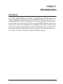
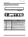
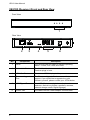
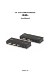
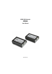
HDMI HDBaseT Extender with USB VE813 User Manual www.aten.com VE813 User Manual EMC Information FEDERAL COMMUNICATIONS COMMISSION INTERFERENCE STATEMENT: This equipment has been tested and found to comply with the limits for a Class A digital device, pursuant to Part 15 of the FCC Rules. These limits are designed to provide reasonable protection against harmful interference when the equipment is operated in a commercial environment. This equipment generates, uses, and can radiate radio frequency energy and, if not installed and used in accordance with the instruction manual, may cause harmful interference to radio communications. Operation of this equipment in a residential area is likely to cause harmful interference in which case the user will be required to correct the interference at his own expense. FCC Caution: Any changes or modifications not expressly approved by the party responsible for compliance could void the user's authority to operate this equipment. CE Warning: This is a class A product. In a domestic environment this product may cause radio interference in which case the user may be required to take adequate measures. Suggestion: Shielded twisted pair (STP) cables must be used with the unit to ensure compliance with FCC & CE standards. RoHS This product is RoHS compliant. SJ/T 11364-2006 The following contains information that relates to China. ii VE813 User Manual User Information Online Registration Be sure to register your product at our online support center: International http://eservice.aten.com Telephone Support For telephone support, call this number: International 886-2-8692-6959 China 86-10-5255-0110 Japan 81-3-5615-5811 Korea 82-2-467-6789 North America 1-888-999-ATEN ext 4988 United Kingdom 44-8-4481-58923 User Notice All information, documentation, and specifications contained in this manual are subject to change without prior notification by the manufacturer. The manufacturer makes no representations or warranties, either expressed or implied, with respect to the contents hereof and specifically disclaims any warranties as to merchantability or fitness for any particular purpose. Any of the manufacturer's software described in this manual is sold or licensed as is. Should the programs prove defective following their purchase, the buyer (and not the manufacturer, its distributor, or its dealer), assumes the entire cost of all necessary servicing, repair and any incidental or consequential damages resulting from any defect in the software. The manufacturer of this system is not responsible for any radio and/or TV interference caused by unauthorized modifications to this device. It is the responsibility of the user to correct such interference. The manufacturer is not responsible for any damage incurred in the operation of this system if the correct operational voltage setting was not selected prior to operation. PLEASE VERIFY THAT THE VOLTAGE SETTING IS CORRECT BEFORE USE. iii VE813 User Manual Package Contents The VE813 package consists of: 1 VE813T HDMI HDBaseT Extender with USB 1 VE813R HDMI HDBaseT Extender with USB 1 HDMI Cable 1.8 m 1 USB Cable 1.8 m 2 Power Adapters 1 Mounting Kit 1 User Instructions* Check to make sure that all the components are present and that nothing got damaged in shipping. If you encounter a problem, contact your dealer. Read this manual thoroughly and follow the installation and operation procedures carefully to prevent any damage to the unit, and/or any of the devices connected to it. * Features may have been added to the VE813 since this manual was published. Please visit our website to download the most up-to-date version of the manual. © Copyright 2015 ATEN® International Co., Ltd. Manual Date: 2015-11-05 ATEN and the ATEN logo are registered trademarks of ATEN International Co., Ltd. All rights reserved. All other brand names and trademarks are the registered property of their respective owners. iv VE813 User Manual Contents EMC Information . . . . . . . . . . . . . . . . . . . . . . . . . . . . . . . . . . . . . . . . . . . . . ii RoHS. . . . . . . . . . . . . . . . . . . . . . . . . . . . . . . . . . . . . . . . . . . . . . . . . . . . . . ii SJ/T 11364-2006. . . . . . . . . . . . . . . . . . . . . . . . . . . . . . . . . . . . . . . . . . . . . ii User Information . . . . . . . . . . . . . . . . . . . . . . . . . . . . . . . . . . . . . . . . . . . . .iii Online Registration . . . . . . . . . . . . . . . . . . . . . . . . . . . . . . . . . . . . . . . .iii Telephone Support . . . . . . . . . . . . . . . . . . . . . . . . . . . . . . . . . . . . . . . .iii User Notice . . . . . . . . . . . . . . . . . . . . . . . . . . . . . . . . . . . . . . . . . . . . . .iii Package Contents. . . . . . . . . . . . . . . . . . . . . . . . . . . . . . . . . . . . . . . . . . . iv About this Manual . . . . . . . . . . . . . . . . . . . . . . . . . . . . . . . . . . . . . . . . . . . vii Conventions . . . . . . . . . . . . . . . . . . . . . . . . . . . . . . . . . . . . . . . . . . . . . . .viii Product Information. . . . . . . . . . . . . . . . . . . . . . . . . . . . . . . . . . . . . . . . . .viii Chapter 1. Introduction Overview . . . . . . . . . . . . . . . . . . . . . . . . . . . . . . . . . . . . . . . . . . . . . . . . . . . 1 Features . . . . . . . . . . . . . . . . . . . . . . . . . . . . . . . . . . . . . . . . . . . . . . . . . . . 2 Requirements . . . . . . . . . . . . . . . . . . . . . . . . . . . . . . . . . . . . . . . . . . . . . . . 3 Display. . . . . . . . . . . . . . . . . . . . . . . . . . . . . . . . . . . . . . . . . . . . . . . . . . 3 Source Device . . . . . . . . . . . . . . . . . . . . . . . . . . . . . . . . . . . . . . . . . . . . 3 Cables . . . . . . . . . . . . . . . . . . . . . . . . . . . . . . . . . . . . . . . . . . . . . . . . . . 3 Operating Systems . . . . . . . . . . . . . . . . . . . . . . . . . . . . . . . . . . . . . . . . 4 Components . . . . . . . . . . . . . . . . . . . . . . . . . . . . . . . . . . . . . . . . . . . . . . . . 5 VE813T (Transmitter) Front and Rear View . . . . . . . . . . . . . . . . . . . . . 5 VE813R (Receiver) Front and Rear View . . . . . . . . . . . . . . . . . . . . . . . 6 Chapter 2. Hardware Setup Rack Mounting . . . . . . . . . . . . . . . . . . . . . . . . . . . . . . . . . . . . . . . . . . . . . . 7 Installation . . . . . . . . . . . . . . . . . . . . . . . . . . . . . . . . . . . . . . . . . . . . . . . . . . 9 Grounding . . . . . . . . . . . . . . . . . . . . . . . . . . . . . . . . . . . . . . . . . . . . . . . 9 Setting Up . . . . . . . . . . . . . . . . . . . . . . . . . . . . . . . . . . . . . . . . . . . . . . 11 Installation Diagram. . . . . . . . . . . . . . . . . . . . . . . . . . . . . . . . . . . . . . . 12 Chapter 3. Operation LED Display . . . . . . . . . . . . . . . . . . . . . . . . . . . . . . . . . . . . . . . . . . . . . . . 13 VE813T (Transmitter) and VE813R (Receiver) . . . . . . . . . . . . . . . . . . 13 Appendix Safety Instructions. . . . . . . . . . . . . . . . . . . . . . . . . . . . . . . . . . . . . . . . . . . 15 General . . . . . . . . . . . . . . . . . . . . . . . . . . . . . . . . . . . . . . . . . . . . . . . . 15 Mounting . . . . . . . . . . . . . . . . . . . . . . . . . . . . . . . . . . . . . . . . . . . . . . . 17 Technical Support . . . . . . . . . . . . . . . . . . . . . . . . . . . . . . . . . . . . . . . . . . . 18 International. . . . . . . . . . . . . . . . . . . . . . . . . . . . . . . . . . . . . . . . . . . . . 18 North America . . . . . . . . . . . . . . . . . . . . . . . . . . . . . . . . . . . . . . . . . . . 18 v VE813 User Manual Specifications . . . . . . . . . . . . . . . . . . . . . . . . . . . . . . . . . . . . . . . . . . . . . . 19 Limited Warranty. . . . . . . . . . . . . . . . . . . . . . . . . . . . . . . . . . . . . . . . . . . . 20 vi VE813 User Manual About this Manual This User Manual is provided to help you get the most from your system. It covers all aspects of installation, configuration and operation. An overview of the information found in the manual is provided below. Chapter 1, Introduction, introduces you to the VE813 system. Its purpose, features and benefits are presented, and its front and back panel components are described. Chapter 2, Hardware Setup, describes the steps that are necessary to quickly and safely set up your installation. Chapter 3, Operation, explains the fundamental concepts involved in operating the VE813 An Appendix, provides specifications and other technical information regarding the VE813. vii VE813 User Manual Conventions This manual uses the following conventions: Monospaced [] Indicates text that you should key in. Indicates keys you should press. For example, [Enter] means to press the Enter key. If keys need to be chorded, they appear together in the same bracket with a plus sign between them: [Ctrl+Alt]. 1. Numbered lists represent procedures with sequential steps. ♦ Bullet lists provide information, but do not involve sequential steps. → Indicates selecting the option (on a menu or dialog box, for example), that comes next. For example, Start → Run means to open the Start menu, and then select Run. Indicates critical information. Product Information For information about all ATEN products and how they can help you connect without limits, visit ATEN on the Web or contact an ATEN Authorized Reseller. Visit ATEN on the Web for a list of locations and telephone numbers: International http://www.aten.com North America http://www.aten-usa.com viii Chapter 1 Introduction Overview The VE813 HDMI HDBaseT Extender is an HDMI and USB Extender that supports HDBaseT and patented ExtremeUSB® technology. The VE813 can extend HDMI and USB 2.0 signals up to 100 meters from the HDMI source using a single Cat 5e/6 cable. The VE813 supports HDMI features such as 3D, Deep Color, 4k2k, CEC and HDCP. It is equipped with USB connectors that provide touch panel control and file transfer functionality. The extender is also great for syncing files and folders between portable and desktop computers. The VE813 is ideal for medical imaging and digital signage. 1 VE813 User Manual Features Implements HDBaseT extension technology using only one Cat 5e cable to connect the transmitter and receiver Anti-jamming – resists signal interference during high quality video transmissions using HDBaseT technology ExtremeUSB® - supports transparent USB 2.0 signals and true plug-andplay (no software or drivers required) Supports Dolby True HD and DTS HD Master Audio Built-in 8KV/15KV ESD protection (Contact voltage 8KV; Air voltage 15KV) USB 2.0 Support* – connects devices such as keyboard, mouse, flash drive, printer, touch panel, USB 1.1 web cameras and other USB devices which require moderate amounts of bandwidth Works with all major operating systems: Windows®, OS X®, and Linux® Rack-mountable *Note: The VE813 supports USB transfer rates of up to 30 Mbps. 2 Chapter 1. Introduction Requirements Display An HDMI display capable of the highest resolution you will be using Source Device The following equipment is required: A source device with an HDMI port A computer or device that is USB compatible USB 1.1 or 2.0 compatible device Cables For optimal signal integrity, and to simplify the layout, we strongly recommend that you use the high quality HDMI Cable that is provided with this package. Cat 5e cable is required to connect the Transmitter and Receiver units. Cable of a lower standard will result in degrading of the video signal. We strongly recommend using Cat 5e cables. For better quality over longer distances, we suggest using 2L-2801 (350 MHz) Low Skew Cable Maximum Cable Distances Connection Distance Computer to Transmitter (VE813T) 1.8 m Transmitter (VE813T) 100 m to Receiver (VE813R) Receiver (VE813R) to monitor 1.8 m 3 VE813 User Manual Operating Systems Supported operating systems are shown in the table, below: OS Windows Linux Version 2000 and higher RedHat 9.0 and higher SuSE 10 / 11.1 and higher Debian 3.1 / 4.0 Ubuntu 7.04 / 7.10 UNIX FreeBSD 5.5 / 6.1 / 6.2 Novell Netware 6.0 and higher Mac OS 10.1 and higher Note: The VE813 does not support an OS that do not support USB. 4 Chapter 1. Introduction Components VE813T (Transmitter) Front and Rear View Front View 1 Rear View 2 No. Component 3 4 5 6 Description 1 LEDs The VE813T has four LEDs to indicate operating status – Power, Link, USB, and Video. 2 Unit to Unit Port The Cat 5e cable that connects the Transmitter and Receiver plugs in here. 3 Firmware Upgrade Port The Firmware Upgrade Port is reserved for technical support. If you would like to upgrade the unit’s firmware yourself, please contact your ATEN dealer. 4 HDMI In Port Connect an HDMI cable from the source device into this port. 5 USB Type B Input The USB cable from your computer or USB controller device plugs in here. 6 Power Jack The cable from the Power adapter connects here. 5 VE813 User Manual VE813R (Receiver) Front and Rear View Front View 1 Rear View 2 No. 6 3 Component 4 5 6 Description 1 LEDs The VE813R has four LEDs to indicate operating status – Power, Link, USB, and Video. 2 Unit to Unit Port The Cat 5e cable that connects the Transmitter and Receiver plugs in here. 3 HDMI Out Port Connect an HDMI display to this port. 4 Firmware Upgrade Port The Firmware Upgrade Port is reserved for technical support. If you would like to upgrade the unit’s firmware yourself, please contact your ATEN dealer. 5 USB Type A Ports Your USB 2.0 devices plug in here. (keyboard, mouse, web cam, flash drive, printers, scanners, cameras, external storage media, Digital Signage) 6 Power Jack The cable from the Power adapter connects here. Chapter 2 Hardware Setup 1. Important safety information regarding the placement of this device is provided on page 15. Please review it before proceeding. 2. Make sure that the power to all devices connected to the installation are turned off. You must unplug the power cords of any computers that have the Keyboard Power On function. Rack Mounting For convenience and flexibility, the VE813 can be mounted on system racks. To rack mount a unit do the following: 1. Remove the two screws on the bottom of the VE813: 7 VE813 User Manual 2. Using the screws provided in the Mounting Kit, screw the mounting bracket on to the bottom of the unit as show in the diagram, below: 3. Screw the bracket into any convenient location on the rack. Note: These screws are not provided. We recommend that you use M5 x 12 Phillips Type I cross, recessed type screws. 8 Chapter 2. Hardware Setup Installation Grounding To prevent damage to your installation it is important that all devices are properly grounded. 1. Use a grounding wire to ground both units by connecting one end of the wire to the grounding terminal, and the other end of the wire to a suitable grounded object. 2. Make sure the computer that the Transmitter connects to and the monitor that the Receiver connects to are properly grounded. Cat 5e cable up to 100 m 9 VE813 User Manual 3. For increased grounding protection, use STP (shielded twisted pair) cable to connect the Transmitter and Receiver units. There are two methods that can be used: a) In addition to the eight paired wires, STP cable also contains a grounding wire. Solder this wire to the RJ-45 connector as shown in the diagram below: b) The second method is to use the STP cable shielding for grounding. In this case, make sure that the shielding makes tight contact with the top inside of the RJ-45 connector as shown in the diagram below: In either case, make sure that the sides of the RJ-45 connector make tight contact with the grounding contacts on the sides of the RJ-45 socket as shown in the diagram below: 10 Chapter 2. Hardware Setup Setting Up Setting up the VE813 HDMI Extender system is simply a matter of plugging in the cables. Make sure that all the equipment to be connected are powered off. Refer to the installation diagram on the following page and do the following: 1. Connect the USB cable supplied with the package to the USB Type B port on the Transmitter (VE813T). Plug the other end of the cable into a USB Type A port on the source device. 2. Connect the HDMI cable supplied with the package into the HDMI input port located on the Transmitter (VE813T). Plug the other end of the cable into the HDMI port on the source device. 3. Use a Cat 5e cable to connect the Unit to Unit port on the Transmitter (VE813T) to the Unit to Unit port on the Receiver (VE813R). 4. Plug one of the power adapters (supplied with this package) into a power source; plug the adapter's power cable into the VE813T’s Power Jack. 5. Use an HDMI cable to connect the HDMI output port on the Receiver (VE813R) to the HDMI display. 6. Plug the cables from the USB devices (mouse, keyboard, flash drive, printer, scanner, web cam, etc.), into their respective USB ports on the Receiver (VE813R). 7. Plug the second power adapter (supplied with this package) into a power source; plug the adapter's power cable into the VE813R’s Power Jack. 11 VE813 User Manual Installation Diagram VE813T Rear View 4 3 Local PC 1 HDMI cable USB cable 2 Cat 5e cable 3 VE813R Rear View 7 5 USB Device 6 12 Chapter 3 Operation LED Display The VE813 Transmitter and Receiver units have front panel LEDs to indicate their operating status, as shown in the tables, following: VE813T (Transmitter) and VE813R (Receiver) LED Indication Power (Green) Lights to indicate that the system is receiving power. Link (Green) Lights to indicate that the connection to the Transmitter and Receiver units are ok. OFF when there is a problem with the connection. USB (Green) Lights to indicate that the USB connection to the host computer is working. Flashes green to indicate that the host is in suspend mode. OFF indicates that the link is inactive. Video (Green) Flashes to indicate normal video activity. Lights to indicate HDCP video activity. OFF indicates that there is no video activity. 13 VE813 User Manual This Page Intentionally Left Blank 14 Appendix Safety Instructions General Read all of these instructions. Save them for future reference. Follow all warnings and instructions marked on the device. This product is for indoor use only. Do not place the device on any unstable surface (cart, stand, table, etc.). If the device falls, serious damage will result. Do not use the device near water. Do not place the device near, or over, radiators or heat registers. The device cabinet is provided with slots and openings to allow for adequate ventilation. To ensure reliable operation, and to protect against overheating, these openings must never be blocked or covered. The device should never be placed on a soft surface (bed, sofa, rug, etc.) as this will block its ventilation openings. Likewise, the device should not be placed in a built in enclosure unless adequate ventilation has been provided. Never spill liquid of any kind on the device. Unplug the device from the wall outlet before cleaning. Do not use liquid or aerosol cleaners. Use a damp cloth for cleaning. The device should be operated from the type of power source indicated on the marking label. If you are not sure of the type of power available, consult your dealer or local power company. The device is designed for IT power distribution systems with 230V phase-to-phase voltage. To prevent damage to your installation, it is important that all devices are properly grounded. The device is equipped with a 3-wire grounding type plug. This is a safety feature. If you are unable to insert the plug into the outlet, contact your electrician to replace your obsolete outlet. Do not attempt to defeat the purpose of the grounding-type plug. Always follow your local/national wiring codes. Do not allow anything to rest on the power cord or cables. Route the power cord and cables so that they cannot be stepped on or tripped over. 15 VE813 User Manual If an extension cord is used with this device make sure that the total of the ampere ratings of all products used on this cord does not exceed the extension cord ampere rating. Make sure that the total of all products plugged into the wall outlet does not exceed 15 amperes. To help protect your system from sudden, transient increases and decreases in electrical power, use a surge suppressor, line conditioner, or un-interruptible power supply (UPS). Position system cables and power cables carefully; Be sure that nothing rests on any cables. Never push objects of any kind into or through cabinet slots. They may touch dangerous voltage points or short out parts resulting in a risk of fire or electrical shock. Do not attempt to service the device yourself. Refer all servicing to qualified service personnel. If the following conditions occur, unplug the device from the wall outlet and bring it to qualified service personnel for repair. The power cord or plug has become damaged or frayed. Liquid has been spilled into the device. The device has been exposed to rain or water. The device has been dropped, or the cabinet has been damaged. The device exhibits a distinct change in performance, indicating a need for service. The device does not operate normally when the operating instructions are followed. Only adjust those controls that are covered in the operating instructions. Improper adjustment of other controls may result in damage that will require extensive work by a qualified technician to repair. 16 Appendix Mounting Before working on the rack, make sure that the stabilizers are secured to the rack, extended to the floor, and that the full weight of the rack rests on the floor. Install front and side stabilizers on a single rack or front stabilizers for joined multiple racks before working on the rack. Always load the rack from the bottom up, and load the heaviest item in the rack first. Make sure that the rack is level and stable before extending a device from the rack. Use caution when pressing the device rail release latches and sliding a device into or out of a rack; the slide rails can pinch your fingers. After a device is inserted into the rack, carefully extend the rail into a locking position, and then slide the device into the rack. Do not overload the AC supply branch circuit that provides power to the rack. The total rack load should not exceed 80 percent of the branch circuit rating. Make sure that all equipment used on the rack – including power strips and other electrical connectors – is properly grounded. Ensure that proper airflow is provided to devices in the rack. Ensure that the operating ambient temperature of the rack environment does not exceed the maximum ambient temperature specified for the equipment by the manufacturer. Do not step on or stand on any device when servicing other devices in a rack. 17 VE813 User Manual Technical Support International For online technical support – including troubleshooting, documentation, and software updates: http://eservice.aten.com For telephone support, Telephone Support, page iii North America Email Support Online Technical Support [email protected] Troubleshooting Documentation Software Updates Telephone Support http://www.aten-usa.com/support 1-888-999-ATEN ext 4988 When you contact us, please have the following information ready beforehand: Product model number, serial number, and date of purchase. Your computer configuration, including operating system, revision level, expansion cards, and software. Any error messages displayed at the time the error occurred. The sequence of operations that led up to the error. Any other information you feel may be of help. 18 Appendix Specifications Function Video Input VE813 Interface 1 x HDMI Type A Female (Black) Impedance 100Ω Max distance 1.8m Video Output Interface 1 x HDMI Type A Female (Black) Impedance 100Ω Video Max. data rate 10.2Gbps (3.4 Gbps per lane) Audio Max. pixel clock 340 MHz Compliance HDMI (3D, Deep Color, 4K) HDCP Compatible Consumer Electronics Control (CEC) Max resolutions/ Distance Up to 4K*@70m (Cat 5e/6) / 100m (Cat 6a); 1080p@100m Input 1 x HDMI Type A Female (Black) Output Control USB Channel Power Connector 1 x HDMI Type A Female (Black) Connector Transfer Rate Environment Physical Properties USB 2.0 (Up to 30 Mbps) 1 x DC Jack (Black) Consumption 5 VDC, 5.75W * Operating temp. 0-50ºC Storage temp. -20-60°C Humidity 0-80% RH, Non-condensing Housing Metal Weight 1.23 kg Dimensions (LxWxH) Carton Lot VE813T: 1 x USB Type B Female VE813R: 3 x USB Type A Female 18.00 x 11.50 x 3.00 cm 5 pcs * 4K supported: 4096 x 2160 / 3840 x 2160 @ 60Hz (4:2:0); 4096 x 2160 / 3840 x 2160 @ 30Hz (4:4:4) **For the VE813R, power consumption will be 13.25W when all 3 USB connectors are occupied. 19 VE813 User Manual Limited Warranty IN NO EVENT SHALL THE DIRECT VENDOR'S LIABILITY EXCEED THE PRICE PAID FOR THE PRODUCT FROM DIRECT, INDIRECT, SPECIAL, INCIDENTAL, OR CONSEQUENTIAL DAMAGES RESULTING FROM THE USE OF THE PRODUCT, DISK, OR ITS DOCUMENTATION. The direct vendor makes no warranty or representation, expressed, implied, or statutory with respect to the contents or use of this documentation, and especially disclaims its quality, performance, merchantability, or fitness for any particular purpose. The direct vendor also reserves the right to revise or update the device or documentation without obligation to notify any individual or entity of such revisions, or update. For further inquiries, please contact your direct vendor. 20