1
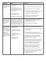
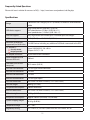
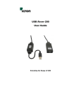
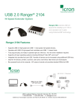
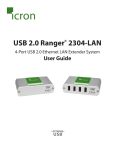
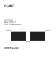
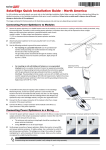
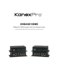
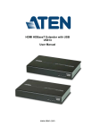
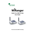
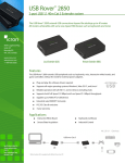
USB 2.0 Ranger® 2104
High Speed Extender System
User Guide
Powered by ExtremeUSB®
Thank you for purchasing the Ranger 2104.
Please read this guide thoroughly before installation.
This document applies to Part Numbers: 00-00234 through 00-00236.
FCC Radio Frequency Interference Statement Warning
Note: This equipment has been tested and found to comply with the limits for a Class A digital device,
pursuant to part 15 of the FCC Rules. These limits are designed to provide reasonable protection against
harmful interference when the equipment is operated in a commercial environment. This equipment
generates, uses, and can radiate radio frequency energy and, if not installed and used in accordance with
the instruction manual, may cause harmful interference to radio communications. Operation of this
equipment in a residential area is likely to cause harmful interference in which case the user will be
required to correct the interference at his own expense.
CE Statement
We, Icron Technologies Corporation, declare under our sole responsibility that the Ranger, to which this
declaration relates, is in conformity with European Standard EN 55022/A1 Class A, and EN 50082-1
(IEC 801-2, IEC 801-3, IEC 801-4)
IC Statement
This Class A digital apparatus complies with Canadian ICES-003.
©2008 Icron Technologies Corporation. All rights reserved. Icron Technologies Corporation, the Icron
Technologies Corporation logo, and the Icron Technologies Corporation products referred to herein are
either the trademarks or the registered trademarks of Icron Technologies Corporation. All other trademarks
are property of their respective owners. Icron Technologies Corporation assumes no responsibility for errors
that may appear in this manual. Information contained herein is subject to change without notice.
No part of this publication may be reproduced, stored in a retrieval system, or transmitted, in any form or by
any means, mechanical, electronic, photocopying, recording, or otherwise, without prior written permission
of Icron Technologies Corporation. Document #90-00524-A01
Contents
Introduction ........................................................................................................ 3
Ranger Product Contents ......................................................................................... 3
Requirements................................................................................................................. 3
About the Ranger ........................................................................................................ 3
Installation guide .......................................................................... 6
Installing the LEX unit ............................................................................................... 6
Installing the REX unit ............................................................................................... 6
Connecting the LEX unit to the REX unit ............................................................ 7
Checking the Installation .......................................................................................... 7
Connecting a USB Device ......................................................................................... 8
Troubleshooting............................................................................ 8
Specifications ................................................................................10
Limited Hardware Warranty ........................................................ 11
Hardware Remedies ..................................................................... 11
Limitation of Liability ...................................................................11
Obtaining Warranty Service ........................................................ 12
Contacting Technical Support ..................................................... 12
Technical Glossary ........................................................................ 14
Introduction
This manual is intended to assist IT professionals install the Ranger 2104. The instructions in this guide
assume a general knowledge of computer installation procedures, familiarity with cabling requirements, and
some understanding of USB devices.
note NOTE: Notes provide additional information that could be useful.
CAUTION: Cautions provide important information about an operational requirement.
Ranger 2104 Product Contents
Your Ranger 2104 is packaged with:
•
Ranger 2104 Quickstart Guide - located on the outer box sleeve (90-00478)
•
LEX unit (Local Extender)
•
REX unit (Remote Extender)
•
REX DC power adapter (1)
• Warranty card
note
An additional DC power adapter may be purchased for the LEX unit in the event that your USB port can not supply
the required 500mA current. Please contact an Icron Sales representative for further details (See Page 15)
Requirements
To complete the installation, you will also require the following items that are not included with the product:
•
USB 1.1 or 2.0 compatible computer (Host computer) with a USB compliant Operating system
•
USB 1.1 or 2.0 compatible device
•
Category 5e Unshielded Twisted Pair (UTP) cable with two RJ45 connectors (if using surface cabling),
OR, Category 5e UTP cabling with two information outlets and two Category 5e UTP patch cords with RJ45 connectors (if using premise cabling)
note All references to Category 5e UTP cable in this document represent the minimum requirement. Category 6 or
better UTP or STP cable may be substituted.
About the Ranger 2104
The Ranger 2104 incorporates Icron’s patented ExtremeUSB® technology, enabling users to extend beyond
the standard 5m cable limit for USB peripheral devices. With the Ranger 2104, USB devices can be located up
to 100 meters from the computer.
The Ranger is composed of two individual units; the LEX unit and the REX unit.
The Power/Config port on LEX and REX can only be used with the included proprietary Ranger 2104
DC adapter. No USB devices can be connected or used on the port.
3
The LEX unit
The LEX unit connects to the computer using the attached USB cable. Power for this unit is provided by the
USB on the host PC. .
Back View
Top View
LEX
5
6
1
2
3
4
7
ITEM TYPE
DESCRIPTION
1
Power LED (Blue)
Light on when power is supplied. Off when no power is supplied.
2
Host LED (Green)
Light on when Host computer is detected and connected to LEX.
3
Link LED (Green) on RJ45
Indicates connectivity between LEX and REX. Lights on both LEX
and REX when link between units is established. Off when there is
no link between LEX and REX.
4
Activity LED (Amber) on
RJ45
Indicates activity on RJ45 port. Blinks intermittently when data is
transmitted between LEX and REX.
5
Extension Link Port (RJ45)
Accepts RJ45 connector for CAT5e UTP cabling (or better).
6
Power/Config port
Connects to the DC Power supply on REX only.
7
USB Type A male connector
Used to connect the LEX unit to the host computer.
4
The REX Unit
The REX unit provides a USB A port for standard USB devices. The REX unit allows you to connect four USB
devices directly. Additional devices may be connected by attaching the USB hubs to the REX unit.
The REX unit is powered by an external DC adapter and can supplies up to 500mA on each USB port.
Front View
USB 2.0 Extender
7
7
7
7
1
2
Rear View
5
6
3
ITEM
4
TYPE
DESCRIPTION
1
Power LED (Blue)
Light on when power is supplied. Off when no power is supplied.
2
Host LED (Green)
Light on when a USB device is attached to REX and connection is
established.
3
Link LED (Green) on
RJ45
Indicates connectivity between LEX and REX. Lights on both LEX and
REX when link between units is established. Off when there is no link
between LEX and REX.
4
Activity LED (Amber)
on RJ45
Indicates activity on RJ45 port. Blinks intermittently when data is
transmitted between LEX and REX.
5
Link Port (RJ45)
Accepts RJ45 connector for CAT5e UTP cabling (or better).
6
Power/Config port
Connects to the DC Power supply.
7
Device Port (USB
Type A female port)
USB device connection.
8
Power port
Connects to the DC Power supply.
9
Device LED (Green)
Indicates when a USB device is connected to the Device Port. Solid
green when device is plugged in and active. Off when device is in
suspend mode or REX unit is powered off.
5
Installation guide
USB extension up to 100m Cat 5 (or better) cable
Before you can install the Ranger 2104, you need to prepare your site.
1.
2.
3.
Determine where the computer is to be located and set up the computer.
Determine where you want to locate the USB device(s).
If you are using surface cabling, ensure you have enough Category 5e UTP cabling to connect the two
locations to the maximum distance of 100m supported by device.
OR
If you are using premise cabling, ensure Category 5e UTP cabling is installed between the two
locations, with Category 5e information outlets located near both the computer and the USB
device(s).
Installing the LEX unit
1.
2.
Place the LEX unit near the computer.
Plug the Type A male connector on the LEX into a USB port on the computer.
Installing the REX unit
1.
2.
3.
Place the REX unit near the USB device(s).
Plug the power adapter into a suitable AC outlet.
Connect the power adapter to the REX unit.
Use only the DC adapters supplied with the Ranger. Use of substitute adapters may cause permanent
damage to the system and will void the warranty.
6
Connecting the LEX unit to the REX unit
To ensure proper operation, it is recommend that only Category 5e or better, Unshielded Twisted Pair (UTP) cabling
note be used to connect the LEX unit to the REX unit. The UTP cabling must have a straight-through conductor
configuration with no crossovers, and must be terminated with 8 conductor RJ45 connectors at both ends. The
combined length of any patch cords using stranded conductors must not exceed 10m.
With Surface Cabling
1.
2.
Plug one end of the Category 5e UTP cabling (not included) into the Link port (RJ45) on the LEX unit.
Plug the other end of the Category 5e UTP cabling into the Link port (RJ45) on the REX unit.
With Premise Cabling
1.
2.
3.
4.
Plug one end of a Category 5e patch cord (not included) into the Link port (RJ45) on the LEX unit.
Plug the other end of the patch cord into the Category 5e information outlet near the Host computer.
Plug one end of the 2nd Category 5e patch cord (not included) into the Link port (RJ45) on the REX unit.
Plug the other end of the 2nd patch cord into the Category 5e information outlet near the USB device.
The maximum length of the Category 5e UTP cable, including patch cords, must not exceed 100 meters. The combined
note length of any patch cords using stranded conductors must not exceed 10m.
Checking the Installation
1.
Check that the Power, Host and Link LED’s are on and that the Activity LED is blinking. If the Link LED
and Activity LED are permanently off then the cabling between the LEX and REX unit is not installed
properly or is defective.
2. For Windows users (2000, XP, or Vista) open Device Manager to confirm that the Ranger has installed
correctly. Expand the entry for Universal Serial Bus controllers by clicking the + sign. If the Ranger has
been installed correctly you should find it listed as a Generic USB Hub.
To open Device Manager in Windows 2000 or XP:
Right click “My Computer” then select: Properties >> Hardware tab >> Device Manager button
To open Device Manager in Windows Vista:
Open the Start menu, right click on “Computer” then select: Manage >> Device Manager
3.
For Mac OS X users open the System Profiler to confirm that the Ranger has installed correctly. In the left hand column under Hardware, select “USB” and inspect the right hand panel. If the Ranger has been installed correctly you should find it listed as a Hub under the USB High-Speed Bus/USB Bus.
4.
If the Ranger is not detected correctly or fails to detect please consult the Troubleshooting Guide.
To open System Profiler in OS X: Open the Finder, select Applications, then open the Utilities folder and double
click on the System Profiler icon.
note
7
Connecting a USB Device
1.
2.
3.
Install any software required to operate the USB device(s). Refer to the documentation for the USB
device(s), as required.
Connect the USB device to the Device port on the REX unit.
Check that the Device is detected and installed properly in the Operating System.
Compatibility
The Ranger 2104 complies with USB1.1 and USB 2.0 specifications governing the design of USB devices.
Icron Technologies Corporation does not, however, guarantee that all USB devices are compatible with the
Ranger as there are a number of different configurations that may impact the operation of USB devices over
extended distances.
Troubleshooting
The following table provides troubleshooting tips. The topics are arranged in the order in which they should
be executed in most situations. If you are unable to resolve the problem after following these instructions,
please contact technical support for further assistance.
PROBLEM
All LEDs on LEX
unit are off.
CAUSE
The LEX unit is not receiving
enough power from the USB port
or the (optional) LEX DC adapter.
SOLUTION
1. Ensure that the Type A USB connector from LEX
to Host computer is properly inserted directly in
a USB port.
2. Move the LEX Type A USB connector to another
USB port on the Host computer.
All LEDs on REX
unit are off
The REX unit is not receiving
power from the DC adapter
1. Ensure that the DC power adapter is properly
connected to the REX unit.
2. Check that the DC adapter is connected to a live
source of electrical power.
3. If the Ranger does not power on, contact
technical support for assistance.
Link LEDs on
LEX unit and
REX unit are off.
There is no connection between
the LEX unit and REX unit.
1. Ensure that a Category 5e UTP cable (or better)
with straight-through conductors is connected
between the LEX unit and REX unit.
2. Connect a short replacement Category 5e patch
cord between the LEX unit and REX unit to deter
mine the defective Category 5e UTP cable or RJ45
termination.
8
PROBLEM
Link LED for RJ45
on LEX unit is on,
Host LED on LEX
unit is off
CAUSE
• The Host computer is not
powered on.
SOLUTION
1. Disconnect all USB devices from the REX unit.
2. Disconnect the LEX unit from the computer.
• The LEX unit is not
connected to the computer
(when used with the optional
LEX AC adapter)
• The computer does not
support USB hubs.
• The Ranger is malfunctioning
Ranger units were
working but the
Host LED on REX
unit is suddenly
blinking
3. Reconnect the LEX unit to the computer.
4. In the Universal Serial Bus controllers section of
Device Manager, check that the Ranger is
recognised as a “Generic USB Hub”.
5. If the Ranger is not recognised, contact
technical support for assistance.
The REX unit is in suspend mode. 1. Recover/Resume the Operating System from
The Operating System may put
Suspend/Standby mode (see your system’s
the Ranger in suspend mode
Operating documentation).
when the computer is put into a
Suspend/Standby state or when 2. Attach a USB device to the Ranger.
no USB devices are attached.
All LEDs on both
• The USB device is
the LEX unit and
malfunctioning.
REX unit are on
but the USB device • The computer does not
does not operate
recognise the USB device.
correctly or is
detected as an
• The application soft
“Unknown Device” ware for the device is not
in the Operating
operating.
System.
• The Ranger 2104 is malfunctioning.
1. Disconnect the Ranger from the computer.
2. Connect the USB device directly to the USB port
on the computer.
3. If the device does not operate properly,
consult the user documentation for the device.
4. Update your system chipset or USB Host
controller drivers from your System/Mother
board manufacturer’s website.
5. If the device operates properly when directly
connected to the computer, connect another
device (of a different type) to the Ranger.
Connect the Ranger to the computer.
6. If the second device does not operate, the
Ranger 2104 may be malfunctioning.
Contact technical support for assistance.
7. If the second device does operate properly, the
first device may not be compatible with the
Ranger 2104. Contact technical
support for assistance.
9
USB device is
attached to REX
USB port but
REX device LED
is off.
• A USB device must have the
1. Install the required USB device driver on the
appropriate driver installed on the computer operating system prior to attaching the
computer operating system.
USB device to the REX unit. Please see your USB
device manufacturer’s website for details.
• The USB device is drawing more
current than allowed by USB
2. Consult your USB device documentation and
specification (>500mA).
power your USB device with the additional, USB
device manufacturer supplied, power supply (if
available).
Frequently Asked Questions
Please visit Icron’s website for answers to FAQ’s: http://www.icron.com/products/usb/faq.php
Specifications
Range
100 meters over Category 5e UTP (or better) stranded or solid conductor
cable
USB device support
High-speed devices (480 Mb/s) (USB 2.0)
Full speed devices (12 Mb/s) (USB 2.0 & 1.1)
Low speed devices (1.5 Mb/s) (USB 2.0 & 1.1)
USB hub support
Any single chain can include up to 4 USB hubs plus one Ranger.
USB host support
EHCI (USB 2.0) and OHCI/UHCI (USB 1.1)
Maximum USB devices
supported (Incl. USB Hubs)
14 USB Devices including any additional USB hubs connected to the REX.
DC adapter(s)
Use only the DC
adapter provided
Input: 100/240 V AC, 50 – 60 Hz
Output: 5 V DC, 1.5 A
DC adapter connector
8-pin Icron custom connector
Power available to USB
device at REX unit
500 mA
USB cable (LEX to Host
computer)
0.15 meters (0.49 ft)
LEX unit USB connector
1 x USB Type A male connector
LEX unit Link connector
1 x RJ45
REX unit Link connector
1 x RJ45
REX unit USB connector
1 x USB Type A port
LEX unit dimensions
43.72 mm x 87 mm x 24 mm (1.72” x 3.43” x 0.95”)
LEX unit weight
0.06 kg ( 0.13 lbs)
LEX power consumption
500 mA Maximum
REX unit dimensions
43.72 mm x 87 mm x 24 mm (1.72” x 3.43” x 0.95”)
REX unit weight
0.05 kg ( 0.11 lbs)
REX power consumption
Approx. 500 mA (No Load). 1A (Full load)
System shipping weight 0.18 kg (0.40 lbs)
Temperature range
0°C – 50°C
Regulatory testing
FCC Class A, IC, CE Class A, EMC EN-61000 4kV Contact, 8kV Air
11
Limited Hardware Warranty
Icron Technologies Corporation warrants that any hardware products accompanying this documentation
shall be free from significant defects in material and workmanship for a period of one year from the date of
purchase. Icron Technologies Corporation’s hardware warranty extends to Licensee, its customers and end
users.
Hardware Remedies
Icron Technologies Corporation’s entire liability and the Licensee’s exclusive remedy for any breach of
warranty, shall be, at Icron Technologies Corporation’s option, either (a) return of the price paid or (b) repair
or replacement of hardware, which will be warranted for the remainder of the original warranty period or
30 days, whichever is longer. These remedies are void if failure of the hardware has resulted from accident,
abuse, or misapplication.
Limitation of Liability
The hardware warranty set forth in this agreement replaces all other warranties. Icron Technologies
Corporation expressly disclaims all other merchantability and fitness for a particular purpose and noninfringement of third-party rights with respect to the hardware.
Icron Technologies Corporation dealer, agent, or employee is authorized to make any modification,
extension, or addition to this warranty. Under no circumstances will Icron Technologies Corporation, its
suppliers or licensors be liable for any costs of procurement or substitute products or services, lost profits,
loss of information or data, or any other special, indirect, consequential, or incidental damages arising in
any way out of the sale of, use of, or inability to use Icron Technologies Corporation product or service, even
if Icron Technologies Corporation, its suppliers or licensors have been advised of the possibility of such
damages. In no case shall Icron Technologies Corporation, its suppliers and licensors’ liability exceed the
actual money paid for the products at issue.
Because some jurisdictions do not allow the limitation of implied warranties of liability for incidental,
consequential, special, or indirect damages, the above limitation may not always apply.
The above limitations will not apply in case of personal injury where and to the extent that applicable law
requires such liability.
12
Obtaining Warranty Service
To obtain warranty service, you must contact Icron Technologies Corporation within the warranty period
for a Return Material Authorization (RMA) number. Icron Technologies Corporation will not accept returns
without an authorized RMA number. Be sure you have the serial numbers of the LEX unit and REX unit
units before calling. Package the product appropriately for safe shipment and mark the RMA number on
the outside of the package. The package must be sent prepaid to Icron Technologies Corporation. We
recommend that you insure it or send it by a method that provides for tracking of the package. The repaired
or replaced item will be shipped to you, at Icron Technologies Corporation’s expense, not later than thirty
days after Icron Technologies Corporation receives the defective product.
Address the returned product to:
RMA Coordinator
Icron Technologies Corporation
4664 Lougheed Highway, Suite 221
Burnaby, BC V5C 5T5 Canada
Tel: 1-604-638-3920
Contacting Sales
Email: [email protected]
Tel: 1-604-638-3920
Contacting Technical Support
Email: [email protected]
To help us serve you better, please include the following information with your technical support request:
•
•
•
•
•
•
Host computer make and model
Type of operating system installed (e.g. Windows XP, Mac OS X, etc.)
Part number and serial number of both LEX unit and REX unit
Make and model of any USB device attached to the Ranger
Description of the installation
Description of the problem
13
NOTES
14
Technical Glossary
Category 5e (CAT5E) Network Cabling
Category 5 cable is commonly also referred to as CAT5. This cabling is available in either solid or stranded
twisted pair copper wire variants and as UTP (Unshielded Twisted Pair) or STP (Shielded Twisted Pair).
UTP cables are not surrounded by any shielding making them more susceptible to electromagnetic
interference (EMI). STP cables include shielding over each individual pair of copper wires and provides better
protection against EMI. Category 5 has been succeeded by Category 5e cabling which includes better
support for high speed communications and reliability.
USB Cables
USB cables have two distinct connectors. The Type A connector (male) is used to connect the cable from a
USB device to the Type A port (female) on a computer or hub. The Type B connector (male) is used to attach
the USB cable to a USB device.
USB Type A
port
USB Type B
port
USB Type A
connector
USB Type B
connector
RJ45
The Registered Jack (RJ) physical interface is what connects the network cabling (CAT5E) to the LEX unit and
REX unit. You may use either the T568A scheme (Table 1) or the T568B scheme (Table 2) for cable termination
as the Ranger uses all four pairs of the UTP cable. RJ45 connectors are also referred to as 8P8C connectors.
RJ45 Pin Positioning
PIN
1
2
3
4
5
6
7
8
Table 1 - T568A Wiring
PAIR WIRE CABLE COLOR
3
1
WHITE/GREEN
3
2
GREEN
2
1
WHITE/ORANGE
1
2
BLUE
1
1
WHITE/BLUE
2
2
ORANGE
4
1
WHITE/BROWN
4
2
BROWN
PIN
1
2
3
4
5
6
7
8
Table 2 - T568B Wiring
PAIR WIRE CABLE COLOR
2
1
WHITE/ORANGE
2
2
ORANGE
3
1
WHITE/GREEN
1
2
BLUE
1
1
WHITE/BLUE
3
2
GREEN
4
1
WHITE/BROWN
4
2
BROWN
Pair 2
Pair 2
Pair 3
1
2
Pair 1
3
4
5
Pair 3
Pair 4
6
7
1
8
2
Pair 1
3
4
5
Pair 4
6
7
8
W-O O W-G B W-BL GW-BR BR
W-GGW-O BL W-BL O W-BR BR
15
Icron Technologies Corporation
4664 Lougheed Highway, Suite 221
Burnaby, BC, V5C 5T5 Canada
Tel: 1-604-638-3920 Fax: 1-604-638-3930
www.icron.com