1
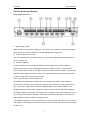
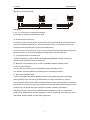
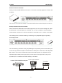
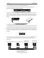
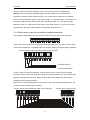
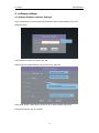
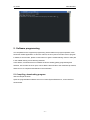
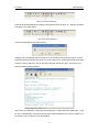
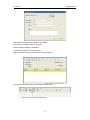
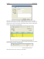
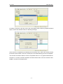
PROGRAMMABLE CENTER CONTROL
SYSTEM
USER MANUAL
TS-9100D
Please read this user manual carefully before using this unit.
TS-9100D
USER MANUAL
Thank you for selecting ITC products. In order for better use of our products, please read
this user manual carefully before installation and debugging. If there is any question,
please contact with ITC or our local agent. Many thanks!
This user manual is just for user operation instruction not in purpose of maintenance
service. There could be any modification onto the product without prior notice.
The copyright of this user manual belongs to ITC company and protected by Copyright of
the People’s Republic of China and other intellectual property. Without ITC written
permission, any imitation, copy, excerpt, translation or other commercial use are
forbidden.
If there is any function or related parameters changed from March 1st 2012, we will make
additional instruction accordingly. Please make inquiry about this condition to ITC
Company.
-1-
TS-9100D
USER MANUAL
Safety Instruction
To ensure the reliability use of the equipment and personnel security, please follow the
below points during installation, operation and maintenance.
Power Supply
Please make sure the ground wire of the power wires is well connected when installation.
Please do not use two-pin plug and ensure the AC power input is 100V-240V 50/60Hz.
Power cord
Proper wiring to avoid any being trampled or squeezed by heavy objects.
Working environment
Please do not put the unit in any undercooling or overheated places and make sure the
working environment is well ventilated. Please turn off the power under humid working
environment or if long time no use.
Maintenance
All the maintenance should be operated by the certified serviceman. Please do not
disassembly the unit or repair it by yourself in case there is danger of electric shock from
the AC high-voltage components in the unit.
Operation Notice
Please make sure to remove the power cord from the AC power socket before following.
operations:
A. Remove or re-build any parts of the equipment.
B. Disconnect or re-build any electric plug or other connections of the equipment.
-2-
TS-9100D
USER MANUAL
Catalog
1. SUMMARY OF PROGRAMMABLE CENTER CONTROL SYSTEM...................................- 4 1.1 System Summary................................................................................................................- 4 1.2Funtional Feature................................................................................................................. - 4 1.3 Control Port.......................................................................................................................... - 5 1.4 Main Technical Parameters............................................................................................... - 5 1.5 Specifications.......................................................................................................................- 5 2. SYSTEM STRUCTURAL SYSTEM............................................................................................- 6 2.1 INSTRUCTION OF THE FRONT PANEL........................................................................- 6 2.2 INSTRUCTION OF THE REAR PANEL.......................................................................... - 7 3. FULL SPECIFICATION OF THE INSTALLATION CONNECTION.......................................- 9 3.1 INSTRUCTION OF INSTALLATION CONNECTION...........................................................................- 9 3.1.1 Full specification of serial control port connection......................................................- 9 3.1.2 Full specification of IR emission port connection......................................................- 11 3.1.3 Full specification of NET port connection...................................................................- 11 3.1.4 Full specification of low voltage relay port connection.............................................- 12 3.1.5 Full specification of user program download port connection................................ - 13 3.1.6Full specification of wireless router connection......................................................... - 13 4. SOFTWARE SETTING...............................................................................................................- 13 4.1 Android Platform software Settings................................................................................- 12 4.2 IOS (IPAD,IPHONE) Platform software Settings......................................................... - 13 4.3 Network platform building................................................................................................ - 13 5. SOFTWARE PROGRAMMING................................................................................................. - 16 5.1 COMPILING, DOWNLOAD PROGRAMMING................................................................................- 16 5.2 IR STUDY.................................................................................................................................. - 19 5.3 IR IMPORTING, COMPILING AND DOWNLOAD........................................................................... - 24 6. TYPICAL APPLICATION CONNECTION DIAGRAM........................................................... - 27 7. COMMON QUESTIONS AND SOLUTIO................................................................................ - 28 -
-3-
TS-9100D
USER MANUAL
1. Summary of programmable center control system
1.1 System Summary
This equipment is based on iOS platform handheld terminal (ipad/iphone, Android) network
center controller, supporting network cascading, realizing intelligent control networking. It is
compatible with tranditional center programming control method. With the luxury and bright
appearance, it will become the new generation intelligent center controller representative and
guide the trend of development in center controller area.
1.2 Funtional Feature
1) Supporting remote network control, built-in network port, supporting network cascading,
supporting ipad/iphone, Android handheld terminal, communication with the main controller via
wifi.
2) Adopting programming control platform with Chinese-English programming interface and
interactive control structure.
3) Adopting latest 32-bit embedded processor, the processing rate is 533MHZ at max.
4) Mostly adopting high integration processing chip, LAY OUT makes the system operation
more stable and smooth.
5) The main controller is built-in 8MB memory and 16MB FLASH storage.
6) Ipad/iphone/Android human-computer interface programming compatible and tranditional
touch screen programming method without new study of new programming method and very
easy to upgrade.
7) 8 independent programming RS-232 control port, which can receive datas in RS232, RS485
and RS422 format.
8) The main controller can be serial looping out. There are 1-8 serial ports that any input can
be looping out from another serial port.
9) 8 independent programming IR emission port, the IR emission port can be used as serial
port and the max qty of programming ports can be up to 16.
10) 8 digital I/0 input output control ports with protective circuit.
11) 8 low voltage relay control port.
12) Supporting remote network control, built-in network port without expansion card.
13) 2 NET network control ports and it can be connected with 256 network equipments at max.
14) Customer can program any control protocol or control code of the setting.
15) Embedded intelligent IR study function module without configurating professional learning
device.
16) Supporting double-code control, that is one key for two kinds of codes.
-4-
TS-9100D
USER MANUAL
17) Supporting hardware study IR function, customer can change the IR equipment at site
without programming once more.
18) You can download different kinds of common equipments IR code datas.
19) There is system software transmitting port on the rear panel.
20) Adopting international SMT processing production technology.
21) Standard 19-inch cabinet design in 1.5U size. Black color oxidation processing is adopted.
to the front panel, which makes the unit more elegant.
22) Environmental protection power supply (110V-240V) suitable to any market needs.
1.3 Control port
1) COM port: 8 DB9/M ports, two-way transmitting signals of RS232, RS485 and RS422.
2) IR port: 8 phoenix socket in size of 5.08mm.
3) Input I/O port: 8 terminal modules with protection circuit, supporting 0-5V digital input signal
4) Low voltage relay port: 8 terminals, normally open independent relay, rated 1A/5V digital
signal.
5) NET port: 2 terminal modules, supporting NET control bus.
6) Network port: one network port.
7) Power line carrier: 1 DB9/F port, monitoring power line carrier status. Power line carrier can
be controlled without any ports.
8) Computer management port: 1 DB9/F port (on rear panel).
1.4 Main Technical Parameters
CPU: 32-bit ARM Microprocessor
Processor: 210MIPS, 533MIPS at max
Standard Memory: 8M SDRAM,16M Flash
Extended Memory: Extendable to 32M
1.5 Specification
Packaging: Metal cabinet, supporting standard 19-inch rack mounting in 1.5U size
Dimensions: 485 Lx236 Wx68 H (mm)
Power Supply: Wide voltage input (110V-240V)
Weight: 2.5kgs
Software: Control System Builder, Chinese-English interface
-5-
TS-9100D
USER MANUAL
2. System Structure
2.1 Front Panel Specification
1. LCD Monitor, can show the current situation.
2. Network data installation button.
3. Network data installation button.
4. Network data installation button.
5. Infrared remote control signal type-in. When learning though Infrared, can use infrared
code to receive remote controller, which is usually used in engineering commissioning
installation.
6. Reset button to reset hardware for Mainframe equipment.
7. ACT situation indicator light to use in the equipment network connecting situation.
8. LINK situation indicator light to use in the equipment working situation.
9. POWER situation indicator light to use in the equipment working situation.
10. Power switch.
-6-
TS-9100D
USER MANUAL
2.2 Rear Panel Specification
Rear panel structure
11. Power supply & fuse
Wide voltage universal power supply port, 100V~240V, more extensive usage, power supply
port with fuse to avoid the sudden high voltage damaging the equipment.
12. 8-channel weak current relay
The circumscribed load can reach DC 5V/1A, use in control projector hanging bracket up an
down occasions, etc.
13. 8-channel digital IO.
Control multi-equipment according to different circumscribed ways. It can be defined
specifically as when receive the signal/PWL from the outside, or when a channel input is
short-circuited with the earth, it can lead to a series of orders/actions of system. It can be also
defined as when trigger the series orders in the system inside to lead to I/O to action so that
control the equipment connected with I/O port.
14&15. 2 pcs NET bus communication port
2pcs based upon 485 agreement NET bus communication port, adopt 4-wire system to
communicate, including 2 wires to transport signals, the rest 2 wires to supply power for the
bus. The bus can support utmost 256pcs compatible NET communication regular. It can
design different ID number in this equipment. It also can communicate with other equipment
according to different ID number. The equipment is constantly scanning the equipment on the
bus to monitor all equipment situations on the bus, and take the right actions in accordance
with situation to reach the perfect controlling effects.
The available equipment to hang on the NET bus is: P8N, CPLRF, which be only 1pcs or more
than 256pcs. The equipment’s ID number should not be the same on the same bus and should
be ONLY one.
-7-
TS-9100D
USER MANUAL
Specifical connection method:
24 Y Z G
Attention:
.
.
..
……
24 Y Z G
24 Y Z G
……
……
……
……
A. 24, Y, Z, G four lines correspond accordingly.
B. it should not be short-circuited among lines.
16. 8-channel IR emission port
A. Support 8-channel IR equipment, among which connect through IR emission stick and any
port of the mainframe equipment 8- channel IR emission ports. It can realize controlling IR
equipment functions intelligently by IR programmed learning.
B. There are two connection ports: Ir(x), G. Ir(x) connects the positive pole (white black line) of
IR emission stick, G connects the negative pole (black line) of IR emission stick.
17. 1pcs Ethernet RJ45 connection port.
Connect the Ethernet or WIFI to realize IPAD/IPHONE/ANDROID wireless controlling or
remote control the whole system by equipment.
18. NET bus communication port to control TS-9169BW colorful touchable screen.
19 &20. channel selection
A. It can select the channel in the compatible and quick touchable screen.
B. It needs to channel installation accordingly when controlling by network.
21. 8pcs serial controlling ports
It can be compatible with RS232, RS422, RS485 communication agreement and realize
dual-controlling. Each connection port Baud Rate can support 300-38400. It can also
circumscribed 8 kinds that have RS232, RS422, RS485 communication agreement connection
port equipment. Each connection port sends/receives code separately without influence. Each
serial port can be spliced with more equipment to realize controlling separately or
simultaneously, but it requires the same Baud Rate and different code. The controllable
equipment is: different kinds of matrix equipment, projector equipment, cloud deck etc. series
with RS232, RS422, RS485 communication agreement.
-8-
TS-9100D
USER MANUAL
Serial Controlling Port (adopt standard 9 needle male head, DB9/M) definition as follows:
Foot position
1
2
3
4
5
6
7
8
9
Explanation
B
RXD
TXD
Y
GND
A
RTS
CTS
Z
22. 1pcs DB9/F procedure downloading port
It is used to support power line communication, whose most merits is to save the reset lines
trouble, simplify the lines structure of the system in the engineering application. It improves the
engineering efficiency to great extent. This function is select able.
3. Installation Connection Explanation
3.1 Installation Connection Explanation
3.1.1 Serial controlling port connecting detailed explanation
Serial controlling port is 2 ranks with 9 needle male head, its pin detailed definitions are as
follows:
Foot position
1
2
3
4
5
6
7
8
9
Explanation
B
RXD
TXD
Y
GND
A
RTS
CTS
Z
It can be known from the above pin definition that the equipment’s serial port can support full
duplex RS-232 communication agreement and full duplex RS-422, RS-485 communication
agreement. Full duplex RS-232 communication occupies 2, 3, 5, 7, 8 total 5 feet (usually can
use 2, 3, 5 feet). Full duplex RS-422, RS-485 communication occupies 1, 4, 6, 9 total 4 feet,
including 4, 9 feet as the sending feet, 1, 6 as the receiving feet.
-9-
TS-9100D
USER MANUAL
RS-232 connection methods
Usually, use the standard RS-232 direct line to connect the controlled equipment. Please refer
the below:
The above is the connection drawing of controlling RGB matrix through equipment serial port.
RS-422, RS-485 connection methods
When use RS-422 or RS-485 communication agreement, the users have to design the cables
by themselves. If need half-duplex to send data, the 4, 9 feet is available. If need full duplex
communication, except use 4, 9 feet to send data, it still needs to use 1, 6 feet to receive data.
The following is the connection drawing of controlling 4-way adjustable light 4-way RM by
RS-485 agreement.
The above drawing controls the 4-way adjustable light 4-way RM by serial communication port
8. You can only select the simplex communication to satisfy due to send order to the adjustable
light module. Thus it only occupies the serial communication port 8 4(Y), 9(Z)these two pin.
Adjustable light module power supply (24V) and the earth can be supported by any port of
3pcs NET port. The detailed connection drawing is as follows:
控主 机mainframe
的串 行 口 serial port
Central中control
6
7
8
接 调光
connect
light 器
modulator
CRV-NET口
9
24 Y Z
G Z Y 24
- 10 -
G
TS-9100D
USER MANUAL
3.1.2 IR emission port connection detailed explanation
The equipment provides with 8–way IR emission port in total and connects with 8 pcs
equipment simultaneously. Please refer the below:
The above drawing can be referred each IR emission port has 2 pins: Ir(x), G, “Ir(x)” means
positive, “G” means the earth. The IR emission stick concludes white black and black lines,
white black line means positive, while black line means negative. Please refer the followed
drawing:
D
DV
3.1.3 NET port connection detailed explanation
The equipment offers total 2 pcs NET network port which is based upon RS-485 agreement.
Thus this network bus can hang 256 pcs equipment in total. RF receiver, P8N etc can be on
this network. NET network supplier power, which makes no additional power supply (expect
the too much network equipment and overload power situation). Connection port definition is
as follows:
24 Y Z
G
It can be seen from the above drawing, NET network bus has 4 lines, the middle two lines
works in signal, the left and right one is 24V direct current power supply and the earth
respectively.
接无 线接
收器receiver
connect
central
wireless
接中 控主
机 control connect
24 Y Z G
24 Y Z G
connect power
connect power
supply
manager
接电
源管
理器
supply
manager
接电
源管
理器
G Z Y 24
connect central control mainframe
connect wireless receiver
connect power supply manager
- 11 -
G Z Y 24
TS-9100D
USER MANUAL
It can be seen from the above drawing, it only connect these 4 lines corresponsively.
Attention: the power supply manager splice line order is different with central control
mainframe, wireless receiver splice line order. The central control mainframe and wireless
receiver from the left to the right are 24V power supply, Y, Z, the earth, which is the adverse of
the power supply manager, from the left to the right are the earth, Z, Y, 24V power supply.
Before the power on, make sure the line order is connected correct or not, if the connector is
correspondent, otherwise it will damage the equipment when power on!
3.1.4 Weak current relay port connection detailed explanation
The equipment total offers 8-way 5V/1A weak current relay port, please refer the below:
These ports can be used to control projector hanging bracket to up and down, or other weak
current switch equipment. The followed is the connection drawing of projector hanging bracket.
接中控主机
connect central
control 的弱电继电器口
mainframe weak current relay port
接吊架的升
connect bracket up
接公共端
connect public port
接吊架的降
connect bracket down
It can be seen from the above drawing, it needs 2-way relay to control projector hanging
bracket to realize. When open B relay, the projector hanging bracket is up; when open A relay,
projector hanging bracket is down. When A & B are flicked simultaneously, which means
stopping projector hanging bracket.
P8N can be controlled through these 8-way weak current relay except through NET port, the
connection methods drawing is as follows:
接中
控 主 机control
的 弱电继
电 器 口 weak current relay port
connect
central
mainframe
电 源 管supply
理 器 的IO
connect接power
IO口port
G 12345678
- 12 -
TS-9100D
USER MANUAL
3.1.5 Users procedure download port connection detailed explanation
The equipment supplies 1 user procedure download port, which can be achieved by 1pcs
standard direct serial line to connect with the equipment and the computer serial port. Please
refer the below:
3.1.6 Wireless route connection explanation
The equipment offers 1pcs Ethernet RJ45 network connection port, which can be achieved by
1pcs above 5 kinds or 6 kinds parallel network cable and wireless route connecting directly.
Please refer the below:
3.2 Network IP and Port installation method
Step 1: under the mainframe standby situation
mainframe front panel
Step 2: click
&
Step 3: move the cursor by
Step 4: click
, click one time one the
button, LCD will show:
simultaneously for 5 seconds
key, change numbers by
;
key.
key to save installation once finished. Remember to check if it is succeed
or not. Power on again to check IP correct or not.
Step 5: install touchable colorful IP address and the central control IP address on the same
network, such as when touchable colorful IP address is “192.168.7.2”, the central control IP
address is “192.168.7.200”.
- 13 -
TS-9100D
USER MANUAL
4. software settings
4.1 Android Platform software Settings
step1, hold down the control interface of the blanks, about 5 seconds later, pop up the
following picture.
In the Password input the itc-panel, click OK.
Step2: enter the system Settings, set up the IP, port, Panel ID
instructions: RTSP: //192.168 XX, XX/ this IP for IP video module, other fixed.
Set after clicking OK, set up complete.
- 14 -
TS-9100D
USER MANUAL
4.2 IOS (IPAD,IPHONE) Platform software Settings
Step1: Double refers to double-click on the control interface, 5 times in a row will pop up the
following picture.
In the Password input the itc-panel, click OK.
Step2: enter the system Settings, set up the IP, port, Panel ID.
instructions: RTSP: //192.168 XX, XX/ this IP for IP video module, other fixed.
Set after clicking OK, set up complete.
4.3 Network platform building
The central host, flat, through the routing path, set in the same network segment, at the same
time with a computer control host and tablet "PING", and the network module, the following
figure:
- 15 -
TS-9100D
USER MANUAL
5. Software programming
It is complicated in the equipment programming, which relates many logical operation, each
functional module application. In this user manual, we don’t plan to introduce how to program
in details, if want to learn, please contact with us to get the related training course or take part
in the related training course learning activities.
In this article, we will introduce more details under the already getting programming files
situation, how to learn the IR on spot, how to add the learnt IR file to the mainframe procedure,
and then how to compile and download in the mainframe.
5.1 Compiling, downloading program
Take a example as below:
Open the programmable software f the host “Control System Builder.exe”, as the interface
shown below.
- 16 -
TS-9100D
USER MANUAL
Open the program set beforehand, as shown in the pictures.
Compiling program, as picture shown below.
- 17 -
TS-9100D
USER MANUAL
Click here to start compilation
First link the downloaded line according to the page as shown in figure 16 , and then operate it
according to the chart shown.
Click here to start download
Then the prompt appears as shown below
Clicking "yes", the program will be froever be in the FLASH of the host the program, and the
program will not be lost when the power is cut off; clicking "No", the program will be temporarily
stored in memory. When it is cut off, the power program will be lost. Here, we choose "yes",
then the following image appears.
Note: when you download, a serial port should be set to: 115200 baud rate, data bits 8, 1 stop
bit. If it is set differently, it will cause the program to download failed, then have to modify it. In
the "Setup" menu, as shown in the figure below.
- 18 -
TS-9100D
USER MANUAL
5.2 Infrared learning
Open the infrared learning software, as the following figure shown.
Click here to open the infrared learning software
Open the infrared learning software, as the following figure shown.
Set up another infrared learning software, as the following figure shown.
- 19 -
TS-9100D
USER MANUAL
Manufacture: Equipment Manufacturer, like SONY
Device Name: Equipment Name, like DVD
Model: Equipment Mode, Like DVD01
Common: Description, can not be filled in
After confirmed, the figure appears as the following shown.
Set up another infrared code, as the following figure shown.
Click here to set up another infrared code
- 20 -
TS-9100D
USER MANUAL
IR Function: IR code name, such as DVD - PWRS, defined as the power on key of DVD.
Other lines can be not filled in. Click "OK" to complete the steps to create a new infrared code.
Repeat this step, and set up all the infrared codes needing to learn. And then to delete default
IR code- "None", as shown in the figure below.
To ensure that the download line has good connection as shown in figure on page 16, and then
open the serial port, as shown in the figure below:
Click here to open the serial port
Start to learn the first IR code, as shown in the figure below
- 21 -
TS-9100D
USER MANUAL
Click here to start to learn the first IR code
As shown in the above, when a waiting dialog box appears, handle the remote control on the
host of the infrared receiving head, and press the key to learn.
As shown in the above, then it prompts learning successfully, click on the "OK" to save the IR
code. Then the software will be prompted whether to go to the next learning code, figure is
shown in the following pages.
- 22 -
TS-9100D
USER MANUAL
As shown in the above, and click "OK" to the next infrared yards of learning. Repeat the above
steps, to learn all of infrared codes, the following message.
Click "Cancel" to complete all the infrared yards of learning. Then, put the IR code files stored.
put the file named "SONY - DVD. Cir. At this point, an infrared learning process is completed.
The next test of infrared codes are correct. First please follow 3.1.2 or graphic linked infrared
emission in 3.2.2 stick, and then selected to test the infrared codes, such as to test the "DVD PWRS", as shown in the figure below.
- 23 -
TS-9100D
USER MANUAL
Select "DVD - PWRS", then click, then the main chance to call a sound, observe whether the
DVD is controlled. If it is not controlled, the code has not been learnt well, repeat the above
steps to learn code; If you can control, the learning code is successfully. Repeat the above
step to test other infrared codes. If learning is successful, you can put the infrared file imports
to the host programming software, and then compile, download to the host.
5.3 The importing, compiliing, and downloading of the IR Code
Choose "Control System Builder. Exe" host programming software menu "Tools" - > "Rebuild
User And Project DataBases", then the following interface:
Click 点击
here to
open打开
the infrared
file
这里
红外 文件
- 24 -
TS-9100D
USER MANUAL
As shown in the above, the system has found a infrared file. Click "ok", and then close the
window. When the infrared file is imported into the software.
Click here to go to the hardware configuration page
File here are imported
Pull the infrared file here, the first infrared emission mouth all the way
- 25 -
TS-9100D
USER MANUAL
At this time, in the logic of programming interface , you will see the logic of the infrared
symbols, as shown in the figure below.
The touchscreen logic symbol on the label should be copied directly to the corresponding to
the position of the infrared logic symbol , as shown in the figure below.
At this point, the infrared learning, importing, has been completed. Next, according to the
method mentioned in section 4.1, compile and download to the host.
- 26 -
TS-9100D
USER MANUAL
6. Typical Application Connection
- 27 -
TS-9100D
USER MANUAL
7. Common Questions and Solutions
1 Why the device ID lights on the NET network does not shine?
A: The reasons are:
1) ID DIP dialed the wrong place;
2) ID code on the device with the software settings are inconsistent;
3) Wiring network is wrong;
4) Network chip burns.
The first three in the case of customers to solve their own checks, the fourth case, is usually
caused by a mistake, this time to contact with manufacturers.
2. When Pressing the touchscreen, why the host did not respond?
A: Check the following steps:
1) When the touch screen, the receiver's ID lamp is flashing;
2) If the ID light does not flash, the touch screen close to the receiver and then test;
3) If the ID lights flash, check whether the receiver is connected with a host of good;
4) Check the host user program.
3. Download the host user program, but why are not all of the equipment controlled?
A: Carefully check the user program, modify it and then try to download.
- 28 -