1
‘ United States Patent
[11]
[191
{45] Mar. 23, 1976
Brobeck et al.
[54]
POlNT-OF-SALE SYSTEM AND APPARATUS
[7 5]
Inventors; William M. Brobeck, Orinda; John
S. Givins, Jr., Berkeley; Philip F.
Meads, Jr., Oakland; Robert E.
[57]
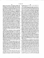
keyboard terminals and associated cash drawers in
June 10, 1974
communication with a control chassis having a micro
computer, a printer and power supply. Each keyboard
[21] Appl. No.: 477,844
terminal has manually operable keys for designating
[52]
US. Cl. ............................ .. 235/168; 340/l72.5
[51]
[58]
Int. Cl.2 .................. .. G06F 15/02; GO6F l5/2O
Field of Search ......... .. 235/l68, I64, I60, 159,
235/l56; 340/1725
[56]
References Cited
UNITED STATES PATENTS
3,253v132
3,267.436
5/1966
8/[966
3,330,947
7/l967
lbw-403
lZ/lg-H
‘
the various items for sale and associated display de
vices which, under the guidance of the computer, dis
play the number of each item ordered. Function keys
are provided for instructing the computer to total the
sales price of each order with automatic tax calcula
tion. Provision is made for the temporary storage of
one or more orders with a recall feature that redis
plays the order. Numeral keys are provided at the key
Pendlewn ,,,,,,,,,,,,,,,,,,,,,,,,, __ 235/163
Alpert et al ............. ..
340/1725
board to give an alternate method of incrementing and
decrementing item quantities and to provide means
Alpert ct al....
.... .. 235/!76
for effecting price and tax changes. Order changes
Ash‘) '3‘ al ---- -
3‘Kl/172-5
''' "
may be effected at any time prior to the total sales
price ‘calculation that enters the sales price and item
3:32? e‘ al"
‘
ABSTRACT
A point-of-sale terminal system including one or more
[73] Assignee: Transac'tron, lnc., Berkeley, Calif.
Filed:-
Primary Examiner-David H. Malzahn
Attorney, Agent, or Firm-Eckhoff, Hoppe, Slick,
Mitchell & Anderson
Thomas, Walnut Creek, all of Calif.
[22]
3,946,220
"""""""""""""""" "
quantlties into the computer’s permanent memory.
13 Claims, 12 Drawing Figures
22
3°)l
an “\
l
@lUOH Oil OllOjl O] [0]
@ml
or
or
atom
@J
a, Q, #1 Q
4@ .
LL
US. Patent
March 23, 1976
Sheet 1 of9
66
3,946,220
22)
@ [B01 <51 0] LOH 0i
FlG.-l
U.S. Patent
March 23,1976
3,946,220
Sheet 2 of 9
22
2
96
62
66
32
‘ION -
2%
we
84
FIG.—3
92)
92)
.9390
80)
82
64
62
FlG.-2
US. Patent
82
7O
88
94
March 23, 1976
88
(H?
4
88
22
u
'
I
IL v
:1. s2
\
A92
94
'
I
' -92
72)
74)
88
I
'
(80
4 88 94
88
94
88 84 64
2$<222>D>H
1
I
3,946,220
Sheet 3 of 9
I
—92
’/
(72
»\__78
"'78
‘
,
,
so)
74)
~18
62
I
\
H1
\
\
'/////////////////////-/////////7
98
F|G.—4
___
CORRECTION NO.I
NORMAL
\
_~
/
CORRECTION No.2
so
_.
—
\ MANAGER
STAND BY
‘
~
US. Patent
I
I
_
March 23, 1976
Sheet7 0f9
3,946,220
-
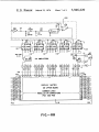
I6 = |
9@1496
15 I413 || l0
02-025
2N 2923
24 AMPLIFIERS
@
U.S. Patent
March 23, 1976
Sheet 8 of9
3,946,220
16
,I I4
CPU
1
\
RANDOM
ACCESS
SWITCHING
READ
~
MEMORY
—
CIRCUIT
le\
ONLY
MEMORY
4__
TAPE
MAGNETIC
DRIVING
CIRCUITS
PRINTER
KEYBOARD
CASH
[20
POWER
SUPPLY
N '0
KEYBOARD
/ I2
CASH
DRAwER
DRAWER
I
F I G.-— l O
52
commou
to bcdefg
FIG-9
(YLINES)
'0
~ '2
3,946,220
1
POINT-OF-SALE SYSTEM AND APPARATUS
record, display and price customer orders as received.
In the preferred form of the invention shown and de
The invention relates to a system for entering cus
scribed herein, the system is intended for use in a so
tomer orders at point-of-sale stations, processing and
called fast food retail outlet.
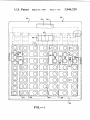
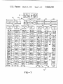
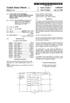
As seen from FIGS. 1, 2 and 4, each of the keyboards
recording said orders in a central computer and return
ing processed order information to said station for
10 comprises a generally rectangular casing 22 having
display.
a desired number of individually operable keys or but
tons 24 provided thereon. The casing 22 is adapted to
In brief, the invention comprises a system having one
be positioned on a counter immediately in front of the
clerk or operator and between the clerk and a customer
on the opposite side of the counter. As shown, the
or more keyboard terminals at point-of-sale stations in
communication with a central computer. Each key
board terminal has a plurality of manually operable
keys for designating the various items offered for sale.
A plurality of display devices are provided on the key
board and each item key has an associated display
device for displaying the number of items being or
casing 22 is of a type commonly used in desk top calcu
lators. The upper surface 26 of the casing has two op
positely sloping portions 28, 30. The larger portion 28
slopes downwardly toward the operator and contains
dered. Means are also provided for generating an iden~
the keys or ‘buttons 24 operated by the clerk when
tifying signal speci?c to each key when said key is
taking the customer’s order. The smaller portion 30
slopes toward the customer, away from, the operator,
actuated. Logic means in the computer actin response
to said signals to cause the display devices associated
with the actuated keys to display the number of items
ordered. The keyboards may also be provided with
numeral keys and, in such case, item quantities may be
entered by successive actuation of the item keys, or,
alternatively, by the actuation of a numeral key fol
lowed by the actuation of an item key. In the latter
and contains a display window 32 in which is shown the
20
25
case, the computer logic means will cause the asso
price of the order.
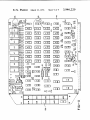
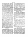
In the embodiment shown in the drawings the key
board is arranged so as to provide 10 numeral keys 34,
40 item keys 36 and 8 function keys 38. There is an
associated display window 40 for each item key and for
certain function keys. The particular number of keys
and the speci?c arrangement of the keys on the key
board may be varied as desired. In the device shown,
the numeral keys 34 are arranged in a single row at the
ciated display device to display a number correspond
ing to the particular numeral key actuated. Provision is
also made for a plurality of function keys on the key
operator’s left. The item keys 36 are arranged in five
board tenninal for designating such steps as cancel 30 rows and occupy the center of the keyboard. The func
tion keys 38 are positioned in a single row at the opera
order, total sales price or store and recall order.
tor‘s right. Additionally, a display window 42 is pro
In the drawings:
vided above the keyboard facing the operator so that
FIG. 1 is a plan view of one form of a keyboard termi
the operator may also see the price of the order when
nal, partly in section;
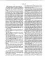
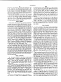
FIG. 2 is a sectional view through the keyboard ter 35 displayed therein. As is more fully described hereafter,
the keyboard is constructed and sealed against the
minal of FIG. 1;
entry of spilled drinks, condiments, salt, and other food
FIG. 3 is a schematic representation of one cycle of
items.
computer operation;
Each keyboard terminal 10 is associated with a cash
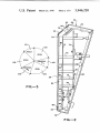
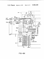
FIG. 4 is a transverse sectional view through the
40 drawer 12 that is preferably mounted underneath the
keyboard terminal of FIG. 1;
counter upon which the keyboard rests. The cash
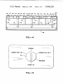
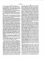
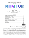
FIG. 5 is a front view of the control switch on the
drawer 12 is controlled by the keyboard terminal so
control chassis for the system;
that access to the cash drawer is under the control of
FIG. 6 is a plan view of one form of menu sheet that
the keyboard at all times. For the present invention the
may be used with the keyboard terminal of FIG. 1;
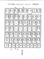
FIG. 7 is a plan view of the upper circuit board of the 45 cash drawer need not be modi?ed from its standard
keyboard terminal shown in FIG. 1;
form as the cash drawer serves the same purpose in the
FIG. 8A is the left hand portion of a schematic dia
gram of the lower circuit board of the keyboard termi
nal shown in FIG. 1;
FIG. 8B is the right hand portion of a schematic 50
present invention as it customarily does in other sys
tems. It is preferred that the cash drawer be magneti
cally operated, that is, that the cash drawer ordinarily
be maintained in its closed condition by an electrically
operated magnetic system which is under the control of
the point-of-sale system.
diagram of the lower circuit board of the keyboard
terminal;
The keyboards l0 and their associated cash drawers
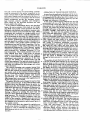
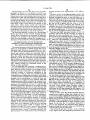
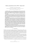
FIG. 9 is a wiring diagram of one form of display
12 are each electrically connected to a control chassis
device which may be used in the keyboard terminal;
55 14. In the preferred form of the invention shown in the
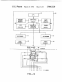
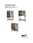
FIG. 10 is a block diagram of the system; and
drawings, two keyboards and cash drawers may be
FIG. 11 is a plan view of the circuit board for the
operated off one control chassis. However, the number
computer showing the central processor unit and the
of keyboards and cash drawers which can be operated
read-only memory (ROM) and random-access memory
from a particular chassis can be varied as desired. For
(RAM) banks.
60
GENERAL DESCRIPTION
The point-of-sale system of the present invention
(FIG. 10) includes one or more keyboard terminals 10
with associated cash drawers 12 in communication with
a control chassis I4 having a micro-computer 16,
example, each keyboard terminal and its associated
cash drawer can be interconnected and arranged to run
with only one control chassis provided the control logic
capability of the computer utilized in the chassis is
sufficient to handle the number of keyboard terminals.
Alternatively, the components making up the chassis
printer I8 and power supply 20.
may be modified. For example, one control chassis may
The keyboard terminals I0 are adapted for use at a
point-of-sale counter window or station and function to
be provided with a printer while additional control
chassis may omit this component. In such an arrange
3,946,220
3
4
ment the control chassis not incorporating a printer
would be connected to the printer component in the
OPERATION OF THE KEYBOARD TERMINAL
As seen from the preferred embodiment of the inven
master control chassis so that the information fed into
each control chassis could be retrieved in the form of a
tion shown in the drawings, the manually operable keys
are arranged with 10 numeral keys 34 in a single row at
printout. In any event, it is necesssary that the control
the left-hand edge of the keyboard. These keys provide
10 single unit numerals, 0 through 9.
chassis arrangement provide the necessary control
logic function, printout capability and emergency
power supply for the keyboard terminals and cash
drawers used in the system.
In the preferred embodiment shown and described
herein, the micro-computer 16 is made up of a single
chip MOS 8-bit parallel central processor unit that is
At the center of the keyboard, 40 food item keys 36
are provided in 5 rows of 8. These food item keys 36
10 are covered with a menu sheet 39 (FIG. 6) that carries
abbreviations for a selected group of food items. For
example, the position for the ?rst food item key 36 at
the upper left comer of the menu sheet bears the ab
breviation “l-IAMB." This stand for the food item —
interfaced with standard semi-conductor memory units
of both the random-access and read-only types. These
components are combined on a single printed circuit
board 44 (FIG. 11) to form a computer assembly capa
hamburger. The food item key position immediately
below bears the abbreviation “CHB." This stands for
the foot item — cheeseburger. Other key positions are
provided with similar notations to indicate regular and
large orders of french fries, regular and large orders of
add, subtract, perfonn logic and counting functions on 20 Coke, regular and large orders of an orange drink,
regular and large orders of root beer, orders for choco
and with these 8-bit numbers or bytes. It is preferred to
late, vanilla, or strawberry milkshakes, one-quarter
use the 8008-] 8-bit parallel central processor unit
pound hamburgers, one-quarter pound cheeseburgers,
manufactured and sold by Intel Corporation. The fea
?sh,
apple pie, milk, coffee, and other similar food
tures and operation of this central processor unit are
ble of performing the functions of a digital computer.
The micro-computer works with 8-bit numbers and can
described and illustrated in a “User's Manual” entitled 25 items. In the menu sheet for the keyboard shown in the
drawings, 40 food item keys are provided but, as previ
“8008 8-bit Parallel Central Processor Unit, MCS-8
ously indicated, additional key positions may be pro
Micro-Computer Set" published November 1972 by
Intel Corporation. This central processor unit can di
rectly address more than 16,000 bytes of external
memory of any kind, such as magnetic core, magnetic
drum, or semi-conductor memories. In the preferred
embodiment semi-conductor memories of the read
only type 46 (ROM) and random-access type 48
(RAM) are employed. The read-only memory units are
employed for program instructions and the random-ac
vided and arranged as desired. It will also be noted that
certain key positions bear no notation. These key posi
30 tions may be used for special food items that are added
after the system is installed. All notations can be
changed by store personnel in a simple and easy man
ner.
The position of each food item key 36 is covered by
35 a colored circle 50 which indicates to the operator the
point to press in order to actuate the key. Each food
cess units are employed for data storage and certain
control functions.
item key 36 is also provided with an associated display
device 52. As shown in the accompanying drawings,
the display device 52 in the preferred embodiment of
the invention comprises a digital numeral display. One
particular numeral display device which may be used in
the invention comprises seven incandescent lighting
The central processing unit contains internal data
registers which are used for counting and operation.
The unit also controls the external devices of the pre
sent system such as the keyboard terminal readings,
strips or bars 54. When the strips 54 are lighted in
printer control and the display windows associated with
proper combinations, the device 52 can display the
the item keys. The central processor units requires
approximately 12.5 micro-seconds per instruction, 45 numerals 0 through 9. The display device 52 also incor
porates a small dot 56 positioned beneath the numeral
display for the indication of numerals in excess of 9.
Other combinations of keys and displays can be used.
which means that it can process in the neighborhood of
80,000 instructions per second.
The printer 18 in the control chassis 14 may be of any
suitable commercial type. In the preferred form of the
invention shown and described herein the printer is a
SEIKO series 101. This model is a two-tape printer with
Keys using a ?exible conducting sheet, keys using reed
50
cross-bar switches, keys operated by the movement of
magnets or capacity sensitive keys may be used.
a split drum and there are 10 columns of characters for
each tape. The split drum rotates continuously and
carries the typeface for printing the desired characters.
Printing is effected by pressing the paper tape and
character ribbon against the typeface by means of actu
ating hammers. The hammers are driven by electro
55
Correspondingly there are many types of numerical
displays than can be used. These include displays
formed of individual lamps, displays using projection of
images of numerals, light-emitting diode and liquid
crystal displays and gas discharge displays.
magnets powered by transistor ampli?ers under the
control of the computer. Magnetic pick-ups sense the
drum position and inform the computer when the ham
switches or switches with mercury-wetted contacts,
keys using metal contacts in air such as leaf-spring or
60
At the right-hand edge of the keyboard 22 a series of
function keys 38 are provided. The top three keys are
designated “grill 1,” "grill 2,” and “grill 3.” Beneath
mer magnets are to be pulsed to print desired ?gures in
these keys are additional keys for the following func
tions: “cancel order"; “clear error”; “no tax" item;
the desired columns.
“total" and “open drawer." The four function keys,
A power supply 20 in the chassis l4 supplied power
for all of the circuits. In addition, a storage battery is 65 “grill 1,” "grill 2,” “grill 3,” and “no tax" also have
associated display devices, however, the display de
included in order to maintain the information in the
vices do not display digital numerals. The display de
RAM memory units in case of a power failure of limited
vices 58 associated with these function keys are merely
duration.
Hill»
3,946,220
5
time, the sale is recorded and the various items incre
mented to the running totals maintained in the com
puter memory. When the clerk is ready to collect the
lights to indicate when the function keys has been actu
ated. There are no display devices associated with the
numeral keys 34 nor with the function keys: “cancel
order,” “clear error,” “tota “ and “open drawer.”
customer’s money the “open drawer” button is pressed
and the cash drawer beneath the keyboard terminal is
opened as previously described. When the “total" key
is actuated, the sale is recorded by incrementing the
ORDER ENTRY
As previously mentioned, the keyboard 22 is adapted
appropriate running totals; the audit tape prints the
to rest on a counter in front of the clerk and between
the clerk and a customer placing an order. As the cus
keyboard number (1 or 2 in the preferred embodi
ment), the amount of tax, the amount of sale including
tax; and the display windows 32, 42 display the amount
of sale including tax. When the “open drawer” key is
tomer gives the clerk the order, the clerk enters the
order by pressing selected key positions on the key
board tenninal. When an item, such as hamburger, is
actuated without the preceding actuation of the “tota "
ordered the item is entered by pressing the hamburger
key position. This entry mode applies to all food item
key, a “total” key is internally simulated before the
“open drawer" key is acted upon. The result is the
keys, hence, to enter an order for a hamburger regular
french fries, and a vanilla milkshake, the clerk or oper
same as though a “total" key had been physically actu
ated before the “open drawer" key. The “open
ator will press the hamburger, regular fries, the vanilla
shake food item keys. As each food item key is pressed
for the ?rst time, the numeral 1 will appear in the asso
ciated display device 52.
Multiple quantities of food items may be entered by
20
the clerk or operator in either of two ways. The clerk
may depress the foot item key 36 as many times as the
item is ordered. Thus, if the customer wishes 5 hambur
drawer” and “total” function keys will not operate
until a food item key is depressed subsequent to the last
actuation of the “open drawer" function key. A new
order is started by pressing either a quantity key or a
foot item key. When this is done, the displays are
cleared to black and the cycle starts anew.
gers the clerk may enter 5 hamburgers by pressing the 25
hamburger food item key 5 successive times. As the
ORDER CHANGES
The above description assumes that quantities and
food items are entered without change. Provision is
made for changes in orders, either because the cus
tomer
has changed his mind or because the clerk makes
numerals l, 2, 3, 4, and 5. Alternatively, an order for 5
hamburgers can be entered by ?rst pressing the nu 30 a mistake in entering the customer‘s order. Changes
hamburger food item key is depressed successively, the
associated display device will sequentially show the
meral key 5 and then the hamburger food item key.
can be made up to the time the “total" or "open
device utilized in the preferred embodiment only dis
plays single digit numbers. For quantities 10 to 15 the
tional quantities have been entered, or by ?rst pressing
drawer" function keys are actuated. No entries are
When these keys are pressed in this sequence the nu
recorded in the computer memory until either the “to
meral 5 will appear in the associated display window 40
tal" or "open drawer" key is actuated.
at the time food item key is depressed.
35
If the order change involves increasing the quantity
In the preferred form of the invention shown and
of a food item ordered this may be accomplished either
described herein, the maximum quantity that can be
by actuating the food item key again until the addi
ordered is 15. This is true even though the display
device displays the second digit in the number as well
a numeral key corresponding to the new quantity and
40
then again pressing the desired food item key. In either
as a dot 56 beneath the display. The dot signi?es a ?rst
of these ways, additional quantities can be added to the
digit of 1. Thus, the quantity 10 is indicated by the
display of the 0 numeral and the lighted dot beneath
the display. The quantity 15 is indicated by a display of
quantities previously ordered.
If it is desired to decrease or decrement the quantity
of the previously ordered food item, this can be done
ing orders for quantities in excess of 9 the clerk ?rst
presses the numeral 1 key, then the second digit of the
number. A zero quantity is indicated by a black space.
The 0 numeral key must be accompanied by the actua
tion of another number in order to light the display 50
device.
the proper food item key. This procedure will enter the
new decremented quantity for that particular food
item. Depression of a numeral key and then a food item
key can be used to change the quantity ordered either
the numeral 5 with a dot beneath the number. In enter 45 by ?rst depressing the correct numeral key and then
In the above described manner, the clerk enters the
up or down.
Individual food items may be cancelled without af
fecting the remainder of the order by depressing the 0
numeral key and then the food item key. The display
quantity and food items selected by the customer until
device associated with the food item will then go black.
the customer's order is complete. When the order is
complete and the customer is ready to pay, the clerk 55 The entire order may be cancelled by pressing the
“cancel order“ function key at the right edge of the
depresses the “open drawer" function key. When the
keyboard terminal. When this function key is actuated
“open drawer" function key is depressed the total price
all displays go black and the revised order may then be
of the customer‘s order, including tax, is displayed both
to the customer and to the clerk and the cash drawer
entered in the manner described above.
clerk but the cash drawer will not he opened. At this
quent customer orders.
beneath the counter is automatically opened. The clerk 60
ORDER STORAGE AND RECALL
may then take the customer's money, make change and
The
keyboard
terminal has the capability of storing
close the cash drawer. If the clerk wishes to display the
orders for later recall. This capability is desirable if the
total price of the customer’s order but is not yet ready
order includes a food item that will require extra time
to collect the money, the clerk may alternatively press
the‘ "total" function key. Pressing the “total" function 65 in preparation. In the present invention, orders may be
entered and stored inde?nitely without interrupting or
key will cause the total price of the customer‘s order,
interferring with the use of the keyboard for subse
including tax, to be displayed to the customer and the
3,946,220
7
8
Once a customer's order is entered on the keyboard
in the manner previously described, it may be stored
for later recall either before or after payment. If the
order is to be stored prior to payment, one ofthe "grill"
since this is an illegitimate sequence. The order will not
be stored.
When the operator sees the error display, he or she is
informed that an illegitimate sequence has been at
tempted and the desired operation has not been carried
function keys is pressed after the order is taken and
entered but before the “total” function key is pressed.
out. The error display condition can be corrected in
either of two ways. The operator may press the “order
If no previous order is in storage, the operator will press
cancel“ function key to clear all displays to black. This
clears the keyboard terminal for any legitimate se
quence. Alternatively, the operator may press the
the “grill 1" function key. When the “grill I” function
key is pressed, the displays for the ordered food items
will go black. At the same time, the display light 58
associated with the “grill 1” key will come on to indi
cate that a food order has been stored in the “grill 1”
location.
The keyboard may then be used to take, price and
record additional customer orders. These orders may
be take and cleared in the normal manner previously
described. Several orders may be taken and cleared
while the stored order is retained in “grill 1” location.
If it becomes necessary to store another order, the
operator stores the order by pressing the “grill 2” func
“clear error" function key. This cancels the attempted
illegitimate sequence without clearing any of the previ
ous legitimate sequences. The keyboard is then re
turned to the same condition it was in immediately
prior to the attempted sequence. Additional entries and
sequences may then be performed as though the erro
neous function has never been tried.
20
tion key. The associated display light comes on to indi'
be performed on random occasions as desired. For the
cate that there is now a stored order at the “grill 2”
location. Inasmuch as there are three order storage
function keys, up to three orders may be stored at a
time. If desired, additional storage capacity can be
MANAGERIAL FUNCTIONS
The control chassis 14 for the point-of-sale system is
adapted to permit a number of managerial functions to
most part, these manager functions involve the printout
of various data accumulated and stored in the com
25
provided.
An order may also be stored after payment. In such a
case, the order is processed as previously described and
puter. Provision is also made for correcting cash
drawer errors and changing both prices and the auto
matic tax computation.
For these purposes the control chassis 14 is provided
with a control switch 60. Accesss to the panel is limited
cash drawer. The operator takes the customer‘s money 30 to the manager by a multiposition key switch which is
operable solely by a special key in the possession of the
and places it in the cash drawer. The operator then
manager. Insertion of the key into the switch 60 is
presses the appropriate “grill" function key to store the
the “open drawer” function key is pressed to open the
necessary to move the switch to the various control
order while it is being prepared.
positions.
To recall a stored order, the operator presses the
appropriate lighted “grill” function key. The associated
display light goes out indicating that that particular
35
“grill” location is available for the storage of another
order. At the same time, the stored order will be redis
Five control positions of the keyswitch 60 are pro
vided in the preferred embodiment of the invention,
shown and described herein. These positions are desig
nated "Manager," “Normal," “Correction 1,” “Cor
rection 2” and “Standby." When the system is in use
the keyswitch is turned to the “Normal” position. In
this position the system is connected to the power sup
ply of the store and power is supplied to the keyboard
terminals, the computer, the printer and the cash draw
played by the various food item display devices exactly
as it was taken prior to storage. If the order was stored
prior to payment, it is completed by the operator as
though it has not been stored. Ordinarily, this will only
involve the pressing of the “total" or “open drawer”
function keys. Additional food items or quantities may
ers. When the store is closed the keyswitch is turned to
be added, however, if necessary. If the order was stored 45 the “Standby" position. This cuts off all power to the
system except for the computer to which power is al
after payment, the total order is again displayed, but
ways maintained. l'lloving the keyswitch out of
the dollar amount which would normally appear in the
price display window 32, 42 is replaced by the notation
“Standby" restarts the computer program at address
“PPP” indicating that the order has been paid for.
O00 O00.
is in either the “Normal” or "Standby" positions, but
may not be removed when the switch 60 is turned to
the other switch positions.
order is stored, pressing that function key has not ef
55
fect.
ERROR DISPLAY
The operation sequences described above, as well as
certain other sequences described later, constitute “le
gitimate" sequences which the computer is pro
grammed to recognize. Any other sequences are “ille
gitimate” and are not recognized by the computer.
Illegitimate sequences resulting from error or unfamil~
iarity with the operation of the keyboard terminal are
indicated by the display of the notation “EEE“ in the
order price display window 42. For example, if the
operator attempts to store an unpaid order after press
ing the “total" key, the error display "EEE” will appear
ill!
'
The manager’s key may be removed when the switch
The price of an order cannot be stored and redis
played. An order can be recalled only if the keyboard
has been cleared. If the operator attempts to store an
order in one of the “grill" locations where an earlier
60
ERROR CORRECTIONS
Provision is made for the correction of erroneous
entries on the part of keyboard operators. Erroneous
entries can be deleted when the manager’s control
switch is turned to the appropriate correction position.
A correction switch position is provided for each key
board terminal connected to the control chassis. To
make a correction the manager inserts his key into the
control switch 60 and turns the switch to the proper
keyboard correction position. In this position the key
65
cannot be removed from the switch. “Cor" is displayed
in the price display window 32, 42 of the keyboard
terminal. The order to be corrected must be displayed
on the keyboard. Pressing the “8” and then “9” nu~
3,946,220
9
10
meral keys automatically corrects the cumulative data
a taxed item but is to be changed to a no tax item the
in the computer since the incorrect amount is sub
tracted from each of the individual items being totalled
“no tax" function key will not be lighted. If it is then
by the computer. Corrections also appear on computer
printouts with a minus sign. A cumulative corrected
sales value is maintained and this total is adjusted every
as a no tax item when the price is changed. If the
change is the opposite, that is, from a no tax status to a
time a correction is made.
change the tax status the “no tax" function key is
pressed. The lighted key will go dark and the item will
pressed, the key will light and the item will be entered
taxable item, the “no tax" function key will light up. To
Since the key cannot be removed from the switch 60
in any of the correction positions, the switch must be
returned to the “Normal’‘ position before the manager
then be entered as a taxable item when the new price is
can retrieve his key. This procedure guards against the
entered.
A printout of the food item prices can be obtained
chance the control chassis will inadvertently be left in
an inappropriate operating condition.
any time during the price change mode by pressing the
“total” function key. Any price changes will be indi
cated by the letter “c.” To leave the price change
DATA MODE
15 mode, the manager presses the “cancel order” function
key. This causes the prices to be printed if a change
A data mode switch location is provided which the
were made.
manager may use to retrieve data stored in the com
puter, to clear certain registers and to change the price
and automatic tax computation functions of the key
board terminals. Each of these operations is initiated by
a particular submode programmed into the computer
20
and carried out at the keyboard terminals. Initiation of
these submodes is effected by turning the manager’s
key to the “Manager" switch position and then by
pressing selected terminal keys. To obtain an hourly
report the “grill 1" function key is pressed. This puts
the keyboard into an hourly report submode and the
letters “Hly” are displayed in the price display window.
25
TAX CHANGE
To enter a change in the automatic tax computation
function, the manager’s keyswitch is first turned to the
“Manager” position. The “no tax” function key in the
keyboard terminal is then pressed to put the keyboard
into the tax change mode. This is indicated in the price
display window 42 which displays the letter “tCh”.
When the keyboard goes into the tax change mode, the
visual display devices associated with the first ?fteen
food item keys will show the numbers 1 through 15 in
sequence. At the same time, the letter “r” will appear
To obtain a daily report submode the “grill 2” function
key is depressed. The display window 42 will show the 30 in the top display device in the center row of the key
board and the letter “d" will appear just below it.
letters “dLY." To obtain the produce mix submode the
To set the initial tax bracket, whatever it may be, the
“grill 3” function key is actuated. This action causes
manager enters the lowest amount upon which the tax
the letters “Pro" to appear in the price display window.
is one cent. To do this, the manager enters the amount
When the desired submode is obtained, the designated
report is printed by pressing the “total” key. The report
35
is cleared by use of the “open drawer" key.
The hourly report gives the total gross sales and the
by pressing the proper numeral keys at the left of the
keyboard. He then presses the food item key opposite
the display device showing the numeral 1. The lowest
total net transactions which have occurred since the
tax bracket amount figure will then appear in the total
last hourly report was taken. The daily report gives the
price display window and the numeral 1 will be dis
played opposite the food item key at the upper right
gross sales, non-taxed sales, tax collected and customer 40
corner of the keyboard. This display informs the man
count for each keyboard since the last clearing opera
ager as to which tax bracket is being displayed. This
tion. It also shows the prior year-to-date gross sales, the
procedure is then repeated for the other 14 tax brack~
prior year-to-date tax collected, the prior year-to-date
ets.
non-taxed sales and the number of manager deletions
for the keyboards. The produce mix report shows the 45 The lowest taxable amount for any tax bracket can be
displayed without change by simply pressing the appro—
quantity of each item sold since the last clearing opera
tion was performed.
priate food item key. In such a case, the amount will be
displayed in the total price display window. Hence, by
PRICE CHANGE
The “Manager" position is also used to make price
and tax changes. To make a price change the keyswitch
is turned to the “Manager" position. Thereafter, the
“spcl. 3” food item key is pressed to place the key
board in the price change mode. The display will show
“PCh“ to indicate that the keyboard is in the price
change mode.
Entry of a new price is accomplished by pressing the
proper quantity keys and then the food item key repre
senting the item being changed. When this is done the
new price will appear in the total price display window
?rst displaying the amount in this manner and then
50
the proper tax computation function for the store can
be visually checked by the manager. If the taxable
amount for any particular bracket needs to be changed,
it may be done in the manner described.
55
keys.
If the item being changed was a no tax item, the “no
tax" function key display device will light up. If it was
To set the applicable tax above the 15th bracket, the
manager enters the tax on $4.00 by pressing the proper
numeral quantity keys. He then presses the food item
key opposite the display with the letter “r. " The man
ager next enters the lowest amount of the next tax
bracket above $4.00 by using the quantity keys and by
then pressing the food item key opposite the display
42 and, at the same time, the letter “P" will appear in
the display device 52 associated with that food item
key. To read the old price being changed prior to entry
of the new price, the particular food item key is pressed
before the new price is entered through the quantity
comparing it against the applicable tax table or chart,
with the letter “d.“
65
Entry of these items into the computer enables the
computer to apply the proper tax computation for al
most every tax jurisdiction in the United States. It has
been found that existing tax structures above $2.54, or
the lowest taxable amount in the lSth bracket, which
ever is less, apply the authorized tax rate calculated to
3,946,220
1l
12
concurrently with the ?rst display device to simulta
the nearest 1/4 of l per cent in one of three ways.
1. In one method, the tax on whole dollars is calcu
neously display the price of the order to the keyboard
operator. Additionally, the keyboard housing has a
large rectangular opening 70 which accommodates the
various keys and their associated visual display devices.
The keyboard construction, in the preferred embodi
ment of the invention shown in the drawings, comprises
lated by application of the tax rate. The tax on any
remaining fraction of a dollar is determined according
to the particular tax bracket breakdown between $1.00
and $2.00, minus the amount of tax on $1.00.
2. In another method, the tax is calculated according
a three-tiered assembly adopted to fit within and under
to the authorized rate and, when the result is a fraction,
always rounds up to the next whole cent.
3. In the third method, the tax is calculated by apply
neath the rectangular opening 70 in the housing 22.
The lower and middle tiers comprise printed circuit
ing the authorized rate but when the result is a fraction,
boards 72, 74 connected together in parallel spaced
the tax is rounded, up or down, to the nearest whole
relationship by screws 76 and cylindrical posts or spac-'
cent.
ers 78. Rectangular bars 80 formed from an electrical
Entering the tax on $4.00 determines the authorized
insulating material are mounted along the peripheral
edges of the upper surface of the upper printed circuit
board 72. The bars 80 locate the keyboard assembly
relative to the housing 22 by bearing against the under
surfaces of the housing 22 de?ning the rectangular
opening 70. A sponge rubber gasket 82 is placed be
tax rate. Since the tax rate is calculated to the nearest
1/4 of l per cent, the use of $4.00 will always determine
the rate to the necessary accuracy.
Entry of the next lowest tax bracket amount above
$4.00 determines which of the three methods of appli
cation is being used. If that amount is $4.01, this identi 20 tween the housing 22 and the bars 80 to effect a liquid
?es the second method-one where the fractional tax is
always rounded up to the next whole cent. If the
tight seal that protects the keyboard assembly against
penetration by spilled beverages.
amount is equal to $4.00 plus the quotient of 0.5 di
The third, or uppermost, tier 84 of the keyboard
vided by the tax rate expressed as a percentage, or
equal to that amount rounded up to the next whole
cent, the method being used is the third method. If the
25
amount of the tax bracket about $4.00 does not indi
cate either the second or third method then by the
process of elimination, the ?rst method is being used.
In this way, the computer is able to identify the tax
method used with respect to amounts over $2.00 and
can apply whichever method is indicated. By reason of
assembly comprises the switches and the display de
vices for the keyboard as well as the covering sheets
which protect and identify them. There is a switch 34,
36, 38 for each key in the keyboard and for most of the
keys there is an associated display device 52. The par
ticular form of the switches and display devices is not of
critical importance since many different types may be
used. As previously explained the keyboard in the pre
ferred embodiment contains ten numeral keys, forty
this capability, the present point-of-sale system can be
food item keys and eight function keys. There is an
used without modi?cation almost anywhere in the
associated display device 52 for each of the food item
United States. This is an important feature for chain or 35 keys 36. These display devices are adapted to display
franchise operations that are nationwide in scope.
the numerals 0 through l5 and also certain letters. In
However, in the particular embodiment of the inven
the form of the invention shown and described herein,
tion shown and described herein, the computer is pro
the switches employed are of the snap-action type.
grammed only for the second method—-the round up
These switches comprise circular metallic disks that are
method.
normally bowed upwardly. Downward pressure on the
A printout of the tax table can be obtained any time
disk, however, brings the center of the disk into en
during the tax change mode by pressing the “total”
gagement with electrical contacts to complete a circuit
function key. Any tax bracket changes will be indicated
and generate an identifying signal speci?c to that par
by the letter “c."
ticular key. Removal of the pressure causes the disk to
To leave the tax change mode, the manager presses 45
snap upwardly to its normal bowed condition and inter
the “cancel order" function key. This causes the tax
rupts the engagement with the contact. As shown, the
table to be printed if a change were made.
switches 34, 36, 38 for the keys are mounted in longitu
dinal strips on narrow printed circuit boards 88. There
CONSTRUCTION OF KEYBOARD TERMINALS
is
a strip of switches for each row of keys. The strips are
50
Each keyboard terminal consists of a stainless steel
fastened to the upper printed circuit board 72 in spaced
casing or housing 22 of the type normally utilized in
relationship by means of screws 90 and spacing posts
desk top calculators. The casing 22 has sides 62 and a
92.
Immediately adjacent the switches are the visual
rounded. The upper surface 26 of the housing 22 is
inclined in two directions. One inclined surface 28, the $5 display devices 52. The display device utilized in the
preferred embodiment of the invention employs seven
greater of the two, inclines downwardly, toward the
separate incandescent lighting filaments which can be
operator. The other inclined surface 30 slopes in an
top 64 but no bottom. All corners and edges are
opposite direction, toward the customer. The front,
back and sides of the casing are generally vertically
disposed. There are three openings in the upper in
clined surfaces of the housing. One opening 66 is lo
cated in the inclined surface facing the customer. This
selectively lighted to form the numerals 0 through 9
(FIG. 9). Each display device is a separate unit and is
60 inserted into a socket strip 94 soldered to the upper
surface of the upper printed circuit board 72. Addi
tional display devices 52 are mounted on the upper
opening accommodates a total price display device 32
printed circuit board beneath the operator’s price dis—
sloping toward the operator. This opening likewise
32. This display device is sealed against the entry of
liquids in the same way as the operator's keyboard.
play window 42. Similarly, still other display devices 52
and fonns therewith a window wherein the customer
can observe the price of his order. A similar opening 68 65 are mounted upon another printed circuit board 96
positioned below the customer‘s price display window
is formed at the upper or outer edge of the surface 28
accommodates a visual display unit 42 which operates
llllll
3,946,220
13
14
printing operation lasts approximately 0.525 millisec
The keyboard is covered with three layers of plastic
onds.
sheeting (not shown) so as to present a smooth wear
As shown in FIG. 9, the lighting displays used in the
surface to the operator. A clear plastic sheet forms the
bottom layer and an intermediate plastic menu sheet is
positioned over this. The intermediate menu sheet 39 is
preferred embodiment of the invention consist of seven
separate incandescent strips, or bars 54, which can be
a translucent white with clear window portions 40 posi
tioned over the display devices 52. Printed legends for
the identi?cation of the various keys are carried by the
There is also a dot S6 at the bottom of the device which
is used to indicate a number greater than 9. For exam
selectively lighted to form the numerals 0 through 9.
ple, the dot 56 is lighted with the strips or bars 54
de?ning the numeral 1 whenever the numeral II is
intended. Any or all of the eight display elements may
be selectively lighted to thereby form a visual display of
menu sheet. Yellow circles 50 are also placed on the
menu sheet. These circles overlie the snap-action
switches and serve to locate for the operator the opera
ble switch portion of each key. A top sheet of a clear,
tough plastic is provided over the menu sheet to take
the wear from the operator’s use of the keyboard.
any desired numeral up to 15. The strips or bars 54 may
also be selectively lighted to form certain letters.
The keys and their associated display devices are
The keyboard assembly is secured to a closure plate
98 for the bottom of the terminal housing 22. The
closure plate is arranged so as to permit the keyboard
assembly to be dropped a short distance downwardly
away from the housing to permit the changing or re
placement of the protective covering sheets of plastic.
identi?ed and located for the computer by means of
three sets of letter coordinates (see FIG. 7). Each of
the keys has an X coordinate and a Z coordinate. There
are 16 X coordinates starting with X0 and ending with
20
X,,,. There are 4 Z coordinates, Z, through Z4. For the
INTERROGATION OF THE KEYBOARD
display devices, there are 16 X coordinates and 3 Y
coordinates. Each Y coordinate is further divided into
TERMINALS AND COMPUTER OPERATION OF
THE ASSOCIATED DISPLAY DEVICES
eight separate segments identi?ed by the letters a, b, c,
banks are programmed to handle several uses on an
individual display devices 52.
Scanning of the keys of a keyboard and the lighting of
the associated display devices is initiated by an output
d, e, f, g, and t. These letter segments are keyed to the
The central processor unit and its associated memory 25 seven incandescent strips 54 and dot 56 making up the
allocation basis. Allocation is accomplished in a man
ner which permits the simultaneous use of two key
signal from the computer to the keyboard. The com
puter output signal carries 32 bits of data which serve
boards and a printer without any noticeable delay in
the functioning of the individual units being served.
Thus, the central processor unit and memory banks
to interrogate the keyboard and to designate which
function to sense key actuations on both keyboards,
display devices are to be lighted. The ?rst 24 data bits
light all display devices as required, operate the printer
and perform all calculations and other logic sequences
are used to carry the instructions designating the Y
called for by the keyboard operators and/or store man
ager, without causing any noticeable delays at the
printer or either keyboard.
To accomplish this, the computer is programmed to
service the keyboards and the printer on a time-sharing
basis. Because of the necessity of servicing the key
boards and printer separately, the operation of the
computer consists in continuous repetitions of the
cycle shown in FIG. 3. That cycle consists of a ?rst
scanning sequence 100 having two phases; a ?rst phase
in which the keys and display devices of keyboard 1 are
scanned, and a second phase in which the keys and
display devices of keyboard 2 are scanned. After the
scanning sequence 100 is completed the computer next
carries out a processing step 102 in which various logic
sequences for keyboard 1 are done as required. The
processing step 102 is followed by a second scanning
sequence 104 just like the ?rst in which the keys and
display devices of keyboard 1 are scanned and then the
keys and display devices of keyboard 2 are scanned.
coordinates and the letter segments of the display de
35 vices that are to be lighted. The next four data bits
(through the use of a 4 to l6 decoder) designate one of
the 16 X coordinates. This designated X coordinate
then serves to identify the keys being interrogated by
the computer on each output signal as well as the par
ticular display devices to be lighted in response to pre
viously sensed key actuations. The ?nal four data bits
of the output signal are blank so that the keyboard may
impress upon these data positions the Z coordinate of
any key being actuated by the keyboard operator.
45
From the computer, the output signal passes in steps
through seven TTL shift registers 112 (FIGS. 8A and
8B) and is then returned to the computer. The ?rst 8
data bits, or byte, will carry the Y, coordinates for
those display devices identi?ed by a Y, coordinate. If
no Y, display devices are to be lighted all 8 data bits
will have a zero voltage. Since a positive voltage is
required to designate a particular display device, 8
blank data bits will pass through the shift registers I12
and return to the computer without turning on any
This second scanning sequence is then followed by a 55 display devices.
second processing step 106 in which logic sequences
If one or more of the ?rst 8 data bits have been im—
for keyboard 2 are performed. A third scanning se
pressed with a positive voltage, that voltage will serve
quence 108 follows and, again, the keys and display
as an instruction that a display device having a Y, coor
dinate is to be lighted. Which Y, display device is to be
step of the cycle, the computer executes a printing 60 lighted will not be known until the X coordinate is also
identi?ed. The X coordinate will be identi?ed by the
operation 110 in which any demands for the printer are
?rst 4 bits of the last 8 bit byte of the computer output
satis?ed. At the end of the printing operation, the com
signal. At the time the Y, coordinate instruction is
puter starts on a repetition of the cycle by initiating
devices of the two keyboards are scanned. In the ?nal
another scanning sequence 100. A complete cycle of
given to the keyboard, the particular letter segments
operations is made 213 times a second. One scanning 65 required to light the necessary strips or dot of the desig
nated display device are also given.
sequence and the following process or printing step
The second 8 data bits, or byte, of the computer
occurs 640 times a second. A scanning sequence lasts
output signal carries the designating instruction for all
approximately 0.975 milliseconds and a processing or
3,946,220
15
16
display devices having a Y2 coordinate. Similarly, the
interrogated in every 16 scans or, to put it another way,
third set of 8 data bits of the output signal carries the
45 times a second.
designating instruction for all display devices having a
The computer output signal imparts instructions to
the keyboard for lighting the display devices and re
ceives data on the Z coordinate of depressed keys only
Y3 coordinate. As mentioned above, the next 4 bits
carries the instruction which will supply the X coordi
nate necessary to identify the display devices to be
when the 32 data bits are located in the proper shift
registers 112. A transfer of information occurs only
lighted and the particular keys to be interrogated.
when the ?rst 8 bit byte is in the position corresponding
to the Y1 connections from the display matrix (FIG.
These 4 bits of data are fed into a 4 to l6 decoder 114
so that one of the 16 X coordinates is designated by
each computer output signal. The ?rst output signal of
32 bits will designate the X0 coordinate. There are
three display devices that have this X coordinate. They
are the devices having the coordinates XoYl, XoYz and
XoYa. If any of the three Y coordinates are also desig
nated, the devices so identi?ed will be lighted. The
maximum number of display devices that can be lighted
by one output signal from the computer is three.
0
5
8B). At the same time, the next 8 bits of data will be
aligned with the Y2 connections and the third 8 bit byte
aligned with the Y3 connections. The next 4 bits of.
data, carrying the determining X coordinate for both
the displays and the keys, will be in shift register 4B
(FIG. 8A) which is interconnected with the 4 to 16
decoder 4C. The ?nal 4 blank data bits will be in regis
ter 68 ready to receive an output signal in the event an
interrogated key has been depressed. With the com
The sixteen output lines from the decoder 114 are
puter
output signal so positioned, the “one shot" cir
not only connected to the matrix 116 of the pin sockets 20
cuit 124 is actuated and the information carried by the
118 for the display devices 52, but are also connected
signal is communicated to the keyboard and any input
to the matrix 120 of pin sockets 122 for the keys on the
keyboard terminal. The designated X coordinate, in
addition to identifying the display devices to be lighted,
also identi?es the particular keys to be interrogated.
Since there are four keys with the same X coordinate,
each output signal from the computer serves to interro—
gate four keys. As described earlier, there are 640
scanning sequences for each keyboard per second. It
takes sixteen scans (sixteen computer output signals)
from the keyboard is impressed upon the last four
blank data bits. The signal then is shifted in steps
through the shift registers 112 to the computer. The
25
next following signal, bearing its instructions and deter
mining X coordinate, follows behind. Its information
will not be released to the keyboard, however, until the
signal is properly aligned as described above. When so
30
to interrogate all keys (coordinates Xo through Xls). A
complete interrogation of all of the keys in a keyboard
aligned, the “one shot" circuit 124 will be energized
again and another transfer of instructions effected.
An enabling circuit 126 is provided to protect the
display devices 52. Since the incandescent strips or
bars 54 are lighted intermittently, a higher voltage is
impressed upon them to compensate for a decay in
is completed in l/40th of a second. This is a su?iciently
short time to insure that all depressions of the keys will
be detected.
35 brightness during the unlighted periods. Should move
When a key is depressed, a circuit is completed
ment of the computer output signal through the shift
which impresses an input signal on the last four data
registers 112 be interrupted and a signal left in the
bits of the computer output signal. If, for example, the
actuating position, the lights could be burned out. Ac
cordingly, the enabling circuit clears the registers 112
operator presses the hamburger key, a circuit is com
pleted between points 9 and 3 on the pin socket 2A
in such an event to protect the display lights.
It should be noted that the X coordinates for the keys
(FIG. 7). Completion of this circuit sends a positive
pulse through line 5 (FIG. 8A) to shift register 6B. This
pulse impresses a positive voltage in the position of the
32nd data bit, thereby identifying the coordinate, Z4.
are not necessarily the same as the X coordinates for
the display devices. The hamburger key used as an
example herein happens to have the same X coordinate
When the output signal returns to the computer, the 45 as its associated display device. However, the X coordi~
locating coordinates XOZ4 are sensed and the computer
nates for the remaining keys are, for the most part,
knows that the “hamburger" key has ban actuated. It
different from the X coordinates for their associated
will then send out an instruction to light the associated
display devices.
display device, XOYD the next time the computer sends
out an XO output signal.
With the make up of the keyboard shown in the
drawings, there are 40 logical display devices for the
food item keys, an additional 4 logical display devices
All pin sockets for keys having the same coordinates
are interconnected in parallel. Thus, contact 9 on pin
socket 2A, having the coordinate X0, is connected in
parallel to point 11 on socket 1A, point 10 on socket
6A, point 16 on socket PG 3 and point 4 on socket 4A.
for the price display and 4 simple, single element light
Actuation of the food item and numeral keys calls for
bulbs 58, making a total of 48 display devices. Inas 55 the lighting of the associated display devices. When the
much as three displays can be lighted during each scan
computer receives a signal that a food item key has
ning phase, only 16 scans are required to cover all
been depressed, it ?rst looks to see if more than one
key has been depressed at the same time. If so, the
displays. In one second, any particular display device
will be lighted 40 separate times since there are 640
computer lights the error display. If only one key has
available scanning phases per keyboard per second.
This lighting frequency is fast enough to make the dis
play appear continuous to the human eye without any
objectionable ?icker.
During each scanning sequence four keys can be
60
been depressed the computer next looks to see if a
numeral key has been depressed. If one has been actu
ated, the display device associated with the food item
lights the number corresponding to the particular nu
meral key actuated. If the next preceding key actuation
interrogated. In 16 scans a total of 64 keys will be 65 was not a numeral key, the pressing of the food item
key will cause the quantity for that food item to be
interrogated. There are 40 food item keys, 8 function
keys and 10 numeral keys in the keyboard shown in the
drawings. Accordingly, each key on the keyboard is
Hill
incremented by one. As explained previously, any
quantity of a particular food item can be incremented
3,946.220
18
l7
by use of the numeral key corresponding to the new
provided in the random access memory. One location is
desired quantity followed by actuation of the food item
key. Alternatively, the quantity can be incremented
sequentially through repetitive actuations of the food
item key. Decrementing can be accomplished only by
provided for the ?rst keyboard processing step, another
location is provided for the second keyboard process
ing step and a third location is provided for the printing
going to a lower quantity numeral key and then actuat
ing the food item key. A particular food item can be
cancelled completely by pushing the zero numeral key
and then the food item key.
operation. At the end of the ?rst scanning sequence —
the one preceding the process step for keyboard 1 —
the computer is instructed to jump to the reference
point, or location, for keyboard 1. The information
stored at this address will tell the computer what it is to
do next. If, during the previous processing step, a logic
COMPUTER PROCESSlNG STEPS
sequence was completed and there is no pending oper
Each scanning sequence of the computer is followed
with either a- processing step or a printing step. In the
processing steps, the computer carries out the logic
sequences called for by the keyboard terminals. The
time elapse for each processing step is 0.525 millisec
onds and, in this time period, the computer can pass
through 210 states.
Many of the operations involved in the processing
step can be accomplished in 210 states or less, but the
ation, the computer will be free to start on a new de
mand should one be called for. However, if the opera
tion in the last processing step was not completed, an
instruction to carry on with another part or quantum of
the operation would have been left in the random ac
cess memory and the computer will be told to initiate
the next quantum in the operation. In the same way, the
reference locations for the other keyboard processing
step and the printing operation are programmed to
either carry on with their respective operations or to
tell the computer to start upon another processing or
calculation, require many more states. In such cases,
printing operation.
the processing operation has to be carried out over a
To carry out the computer program, additional read
number of processing steps. This means that an opera 25
more complicated operations, such as the total price
tion once begun is interrupted by further scanning
sequences, by the processing step for the other key
board and by the printing step. The program for the
computer is designed to allow this interruption of the
processing operation and is, accordingly, divided into
separate parts called quanta. Each quantum is a part of
the program operation that can be accomplished within
210 states. Each quantum must be self-contained so at
only memory is required over that provided for on the
printed circuit board of the central processor unit.
Accordingly, nine additional ROM units 128 were
mounted at the left side of the printed circuit board 44
30 (FIG. 11).
,
During idle periods, the processor compares three
identical copies of the price and tax tables, correcting
any discrepancies that arise by majority logic. A cumu
lative count of detected errors is maintained and
its conclusion, no information is left in the central pro
cessor unit. The start of the next succeeding quantum 35 printed with the hourly report.
in the operation must be set up so that the operation
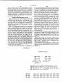
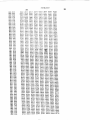
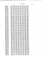
The complete computer program is set forth in Ap
can be picked up and continued during the next pro
pendix l and the various internal processor operating
cessing step for that keyboard.
instructions of the central processor unit are set out in
To do this, three'reference points or locations are 40 Appendix II.
APPENDIX I
Program Legend
XXX O00
DDD: DDD:
XXX O10
DDD: DDD:
XXX 3 7O
DDD: DDD:
1 ROM
No.5
Address
The octal content
Contents
( DDD ) of ROM XXX from octal
address 000 to address 377 is listed from left to
right and top to bottom. Each data word is termin
ated by a colon (
).
The address of only the first
data word in each row is provided.
000 .000
U10
030 O20
030 O30
O40
250: 131 I I31 : 007: 600 : 000: 000: 000 :
056: 010! 066: 31a: O36: i on: 373: 060:
076: 020: 060: 076: O03: 056: 01 2: 005:
127: I06: 240i O15: 066: 277: 056: O1 2 :
076: 002: O50: 076: 002 z 066: 377 : 046 r
3,946,220
20
19
O50
O60
070
100
l 10
120
130
:40
I50
I60
I70
200
2:0
220
230
21:0
250
26C)
270
300
320
150: 371:: 051 I 371::
371::
000 : 002: 300: 106:
375: :01:: l l l : 002:
l l l : 01m: :60: 071::
300: 300: 006: :00:
276: 004:: 076: 040:
050: 374:
277:
300:
3014:‘ 02a: 005: 065: 357:
076: :55: 101:: 007: 002:
0: 1 l
371 :
245:
022:
371 :
060:
066:
002:
3:6:
101::
066:
375:
310:
2'30:
002:
076:
O6: :
076:
375:
066:
000:
036:
:60:
076:
305:
060:
101::
023:
1:2: 001 :
0:3: 002:
001 : 066:
010: 10“
036: 006:
0:0: 371:
3:7: 0:0:
040: 060:
307: 066:
0140: 37a:
373: :06:
002: 066: 056:
372: 367 : 31:6:
150: 274:: 000:
036: 003: I10:
006: 271:: 370:
370: 066: 375:
250: 066: 370:
l ‘.0: 162: 000:
1 56: 076: 02: :
0:3: 002: 066:
150: 260: 000:
356: 371 : 101::
354: 066: 362:
375: 076: 021::
101:: 007: 002:
0:0: :04: 007:
071:: 01:0: 150:
065: 375: 076:
002: 076: 020:
31:0: 000: 066:
100: V007 3 002:
01:14: 360: O76:
060: 37: : 036:
001:: 066: '375:
:04: 007: 002:
0
: 0:3: 032:
0:6: O35:
002! 021 : O40:
005: 021:: O03:
0:0: 027: 04:6:
362: 076: 000:
076: 00: : :04:
372:
051 :
370: 0a: :
365: 066:
207: :00:
077: 21:: z
36: : 317 : 066:
O56: 00: z
076: 000 : 066:
007 : 03b: 00a:
076: 1 17 : 036:
372: 367 : 307 :
:06: 226: 005:
002: 101:: 007 :
307 : 263: :20:
320: 036: 01 I :
004: 005: 002:
370: 060: 37: :
270: 002: 036:
060: 076: 0:6:
036: 00!: 0'33:
04: I 007: 026:
04:4: 0:2: 03: :
01:7: 0:5: 031::
00: : O20: 037:
076: 030: 066:
076: 072: 060:
066: 360: 347: 04: I
0146: 010: 061 :
066: 256: O76:
066: 375: 076:
357: 3:7: 006:
000: 0:7:
003: 022:
006: 025:
0: l : 030:
0:4: 033:
066: 360:
066: 375:
365: 00: :
0:2:
066: 365:
060: 307:
155: 307 :
007: 002:
:04: 050:
036: 007:
37: I 036:
076: 006:
37A:
:06: 310: 006:
074: 0:2: :50:
066: 375: 370:
066: :56: 076:
00: :
1:0:
0: : :
:04:
:60:
:04:
:77:
036:
:63:
:04: 246: 011::
:65: 00: I 06: :
066: 375: 076:
007: 002: 060:
06: : 306: 066:
256: 367: 370:
370: 066: 365: 307: 06: : 267: 06: :
1:0: 050: 00: : 066: :56: 307: 066:
370: :04: 0:3: 002: 066: :56: 076:
066: 367: 3:7: 06: I 327 : 061 : 37: :
06: I 372: 066: :73: :04: 243: 006: 066:
:63: 076: :00: 061: 076: :00: O6: : 076:
2:3: 06: : 076: 200: 066: 356: 076: :74:
066: 375: 076: 3:: I 036: 005: :04: 007:
002: 066: 356: 307: 021:: 00: : 370: 071::
:70: 036: 0:3: :60: 000: 002: 360: 024:
:20: 330: 307: 260: 1:0: 30: l 00: : 006:
012: 07A: 2:5: : :0: 347: 00: : 250: 360:
31:5: 056: 003: 307: 01m: :77: 363: 35M
370: 036: 002: :04: 007: 002: 030: 101::
007: 002: 325: 302: 324: 322: 322: 377:
066: 375: 076: 262: 060: 076: 02a: 03::
1:0: 007: 002: 056: 0:3: 066: 057: :05:
071:: 020: 102: 077: 002: 05: : :03: 07A:
020: 102: 077: 002: 06: : 307: 00a: 001 :
Dan: 0:7: 370: 3:0: 002: 20: : 360: 307:
30: :
:23: 060: 307: :23: 060: 307: :23:
307:
060:
125:
307:
:23: 06: : 06: : 050:
277:
:25: 060: 307: :25: 30: : :25: 007:
377:
076:
053:
260:
30:
:
370:
053: 317:
007: 106: 371:: 0:0: 05: : :06: 374: 012:
300: :06: 371:: 0:3: :04: 1 :1 : 002: 036:
377:
003: l :0: 276: 001:: 066: 276: 076:
000:
066: 375: 076: 000: :04: 372: 000:
307:
030: :00: 270: 002: 000: 066: 057:
0:7:
004:
320:
370:
364:
076: O00: 066:
256:
267:
375:
257:
002 :60
066:
373:
‘000:
066:
160: