1
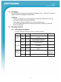
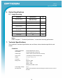
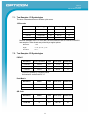
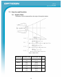
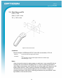
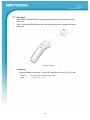
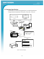
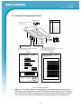
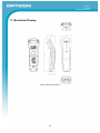
2D Barcode Scanner
OPI 4002
The OPI 4002 is a 2D barcode scanner that •provides
wireless communication compliant with IEEE
802.15.4 between the OPI 4002 and a host system.
Specifications Manual
Opticon
OPI 4002
Specifications Manual
All information subject to change without notice.
Document History
Model Number:
OPI 2002
Specification Number:
SS06077
Edition:
1A
Original Spec Number:
SS06076
Date:
2006-12-22
Copyright 2006 Opticon. All rights reserved.
This manual may not, in whole or in part, be copied, photocopied, reproduced, translated or converted to any electronic or
machine readable form without prior written consent of Opticon.
Limited Warranty and Disclaimers
PLEASE READ THIS MANUAL CAREFULLY BEFORE INSTALLING OR USING THE
PRODUCT.
Serial Number
A serial number appears on all Opticon products. This official registration number is directly related to the device
purchased. Do not remove the serial number from your Opticon device. Removing the serial number voids the warranty.
Warranty
Unless otherwise agreed in a written contract, all Opticon products are warranted against defects in materials and
workmanship for two years after purchase. Opticon will repair or, at its option, replace products that are defective in
materials or workmanship with proper use during the warranty period. Opticon is not liable for damages caused by
modifications made by a customer. In such cases, standard repair charges will apply. If a product is returned under
warranty and no defect is found, standard repair charges will apply. Opticon assumes no liability for any direct, indirect,
consequential or incidental damages arising out of use or inability to use both the hardware and software, even if Opticon
has been informed about the possibility of such damages.
Packaging
The packing materials are recyclable. We recommend that you save all packing material to use should you need to
transport your scanner or send it for service. Damage caused by improper packaging during shipment is not covered by
the warranty.
Trademarks
Trademarks used are the property of their respective owners.
Opticon Inc. and Opticon Sensors Europe B.V. are wholly owned subsidiaries of OPTOELECTRONICS Co., Ltd., 12-17,
Tsukagoshi 4-chome, Warabi-shi, Saitama, Japan 335-0002. TEL +81-(0) 48-446-1183; FAX +81-(0) 48-446-1184
SUPPORT
USA
Europe
Phone: 800-636-0090
Email: [email protected]
Email: [email protected]
Web: www.opticonusa.com
Web: www.opticon.com
2
Opticon
OPI 4002
Specifications Manual
Contents
1. Abstract ........................................................................................................................................ 6
2. Overview ...................................................................................................................................... 6
3. Physical Features ........................................................................................................................ 7
3.1. Dimensions .......................................................................................................................... 7
3.2. Weight .................................................................................................................................. 7
3.3. Color .................................................................................................................................... 7
4. Environmental Specifications .................................................................................................... 7
4.1. Operating Temperature and Humidity .................................................................................. 7
4.2. Storage Temperature and Humidity ..................................................................................... 7
4.3. Ambient Light Immunity ....................................................................................................... 8
5. Electrical Specifications ............................................................................................................. 8
5.1. Main Battery ......................................................................................................................... 8
5.2. Battery Operating Time and Charging Time ........................................................................ 8
5.3. AC Adaptor .......................................................................................................................... 9
5.4. Operating Indicators ............................................................................................................. 9
5.4.1.
LED Indicator and Buzzer ......................................................................................................... 9
6. Optical Specifications ............................................................................................................... 10
6.1. Imager Scanning ................................................................................................................ 10
7. Technical Specifications........................................................................................................... 10
7.1. Test Samples: 1D Symbologies ......................................................................................... 11
7.2. Test Samples: 2D Symbologies ......................................................................................... 11
7.3. Print Contrast Signal (PCS) ............................................................................................... 12
7.4. Minimum Resolution .......................................................................................................... 12
7.5. Scan Area and Resolution ................................................................................................. 13
7.5.1.
Depth of Field ......................................................................................................................... 13
7.6. Pitch, Skew, and Tilt .......................................................................................................... 14
7.7. Curvature ........................................................................................................................... 15
8. Aiming ........................................................................................................................................ 16
8.1. Aiming Patterns .................................................................................................................. 16
8.2. Aiming Guidelines .............................................................................................................. 16
9. Interface Specifications ............................................................................................................ 17
9.1. Wireless Interface .............................................................................................................. 17
3
Opticon
OPI 4002
Specifications Manual
9.2. IEEE 802.15.4 .................................................................................................................... 17
9.2.1.
Radio Equipment .................................................................................................................... 17
9.2.2.
Frequency Band ..................................................................................................................... 17
10. Default Settings ......................................................................................................................... 18
10.1. Set Default Interface .......................................................................................................... 18
10.1.1. Default Settings ...................................................................................................................... 18
10.2. Configuring Settings by Reading Menu Barcode Labels ................................................... 18
10.2.1. Address Registration to Connect with OPA 1001 ................................................................... 18
10.2.2. Wireless Communication Channel Settings: CH11–CH26 ..................................................... 18
10.2.3. Data Memorizing Settings Outside the Communication Range: DTME/DTMD ...................... 18
10.3. Default Settings 1: Readable Codes .................................................................................. 19
10.4. Default Settings 2: Read Options, Trigger, Buzzer ............................................................ 20
10.5. Default Settings 3: Other Communication Settings ............................................................ 21
11. Serial Number and Labeling ..................................................................................................... 21
11.1. FCC Label .......................................................................................................................... 21
12. Packaging Specifications ......................................................................................................... 22
12.1. Collective Packaging Specification .................................................................................... 23
13. Durability .................................................................................................................................... 24
13.1. Electrical Noise .................................................................................................................. 24
13.2. Static Electricity .................................................................................................................. 24
13.3. Shock ................................................................................................................................. 24
13.3.1. Drop Test (without packaging) ................................................................................................ 24
13.3.2. Drop Test (with individual packaging) ..................................................................................... 24
13.4. Vibration Strength .............................................................................................................. 24
13.5. Dust and Drip Proof ........................................................................................................... 25
14. Reliability.................................................................................................................................... 25
15. Regulatory Compliance ............................................................................................................ 26
15.1. LED Safety ......................................................................................................................... 26
15.2. Product Safety ................................................................................................................... 26
15.3. EMC ................................................................................................................................... 26
15.4. RoHS ................................................................................................................................. 26
15.5. R&TTE ............................................................................................................................... 26
15.6. Radio Law .......................................................................................................................... 27
15.7. State of California: Perchlorate Best Management Practices ............................................ 27
4
Opticon
OPI 4002
Specifications Manual
16. Safety .......................................................................................................................................... 28
16.1. Shock ................................................................................................................................. 28
16.2. Temperature Conditions .................................................................................................... 28
16.3. Foreign Materials ............................................................................................................... 28
16.4. Other .................................................................................................................................. 28
16.5. AC/DC Adapter .................................................................................................................. 28
17. Mechanical Drawing .................................................................................................................. 29
Table of Figures
Figure 1: Depth of field ................................................................................................................ 13
Figure 2: Pitch, skew, and tilt....................................................................................................... 14
Figure 3: Curvature...................................................................................................................... 15
Figure 4: Aiming patterns ............................................................................................................ 16
Figure 5: Serial number diagram ................................................................................................. 21
Figure 6: FCC label ..................................................................................................................... 21
Figure 7: Individual packaging ..................................................................................................... 22
Figure 8: Collective packaging .................................................................................................... 23
Figure 9: Mechanical drawing ..................................................................................................... 29
5
Opticon
OPI 4002
Specifications Manual
1. Abstract
This manual provides master specifications for the OPI 4002 2D barcode scanner (hereafter
referred to as “scanner”).
2. Overview
The OPI 4002 includes the following features:
•
A 1.3 million-pixel (SXGA) CMOS area image sensor, and a compact camera module
with wide-angle lens that enables scanning of wider symbologies at higher resolution
•
Wide-angle lens optics that make it possible to scan wider symbologies at closer
distances
•
A small, high-performance, power-saving decoder that processes data faster and
provides smoother scanning of both linear (1D) and 2D symbologies
•
Wireless communication compliant with IEEE 802.15.4 (an interface standard for ZigBee
physical layer and MAC layer) is the interface between the OPI 4002 and a host system
•
The scanner is supplied with an IEEE 802.15.4 dongle to establish wireless
communication through the USB port of hosting hardware.
•
Scanner settings can be configured by scanning menu labels.
•
A lithium-ion secondary battery is used as the power supply for the scanner.
•
Connect a dedicated AC adapter or an optional charger directly to the OPI 4002 to
charge the battery.
•
The OPI 4002 complies with the Restriction of Hazardous Substances (RoHS).
6
Opticon
OPI 4002
Specifications Manual
Supported symbologies:
Linear (1D)
Postal Code
2D
JAN/UPC/EAN, incl. add-on
Chinese Post
Aztec Code
Codabar/NW-7
Korean Postal Authority Code
Aztec Runes
Code 39
Composite Codes
Code 93
Data Matrix (ECC 0-140, ECC200)
Code 128
Maxi Code (mode 2~5)
GS1-128 (EAN-128)
MicroPDF417
GS1 Databar (RSS)
Micro QR Code
IATA
PDF417
Industrial 2of5
QR Code
Interleaved 2of5
ISBN-ISSN-ISMN
Matrix2of5
MSI/Plessey
S-Code
Telepen
Tri-Optic
UK/Plessey
3. Physical Features
3.1. Dimensions
W 58.1 mm x D 42.4 mm x H 163.9 mm
3.2. Weight
125 grams, max.
3.3. Color
Light gray
4. Environmental Specifications
4.1. Operating Temperature and Humidity
Temperature: 0 to 40° C
Humidity: 5 to 90% RH
4.2. Storage Temperature and Humidity
Temperature: -20 to 60° C
Humidity: 5 to 90% RH
7
Opticon
OPI 4002
Specifications Manual
4.3. Ambient Light Immunity
Decoding performance is guaranteed when the range of illumination on a barcode
surface is between zero and the following values:
Incandescent light
to 10,000 lx
Fluorescent light
to 10,000 lx
Sunlight
to 100,000 lx
Direct light or specular reflection from a light source should be prevented from entering
the acceptance area.
5. Electrical Specifications
5.1. Main Battery
The main battery is a lithium-ion secondary battery.
Nominal capacity: 1100 mAh
Nominal voltage: 3.6 V
Item
Consumption
current
Specifications
Conditions
15 mA (max.)
When idle
250 mA (max.)
When scanning
550 mA (typ.)
When charging
5.2. Battery Operating Time and Charging Time
Items
Specifications
Conditions
Battery life
30 hours (min.)
1 scan / 5 s
Discharge and charge 300 times
Battery capacity 70% (1C charging)
Charging time
3 hours
Time necessary to fully charge an empty battery
Note: Battery life may be shorter than specified above when the quality of the battery
pack is degraded.
Conditions
Ambient temperature: +25°
Symbology: 1-digit Code 39, PCS = 0.9, Resolution = 1.0 mm
Distance: 85 mm from the front edge of the scanner. (Single read)
8
Opticon
OPI 4002
Specifications Manual
5.3. AC Adaptor
The OPI 4002 can be charged by an optional AC adapter of 6.0 V / 750 mA. This optional
adapter is used for charging the internal battery.
Conditions
Connect 1Ω resistance to a power supply line in series and measure the current by
the voltage between both ends of resistance.
Power supply voltage is measured at a connector terminal area.
The current value depends on the interface type and host computer to which the
device is connected.
5.4. Operating Indicators
5.4.1. LED Indicator and Buzzer
The OPI 4002 uses LEDs and a buzzer to indicate its status.
State
Color
Display
Operating State
Buzzer
Red
Lighting
Shows that the scanner is being
charged.
-
Green
Lighting
The light changes from red to green
when charging is completed.
-
Green
Blinking
Shows that the scan or transmission was
executed normally.
Trrr
Red
Blinking
Shows that the data could not be
transmitted.
Pip, Pip, Pip
Orange
Blinking
Shows that the data is being stored in
memory.
Trrrrrrrrrrr
Green
Lighting
Red
Lighting
Charging
Scanning
Shows that registration was completed.
Wireless
Connection
Peeeeeeeeep
(Completion of
Registration)
Shows that registration failed.
9
Pip, Pip, Pip
Opticon
OPI 4002
Specifications Manual
6. Optical Specifications
6.1. Imager Scanning
Parameter
Specification
Unit
Scanning method
CMOS area sensor
(black and white)
—
Effective pixels
1280 (H) x 1024 (V)
dots
Frame rate
30
fps
Aiming LED wavelength
(2 green LEDs)
527
nm
Lighting LED wavelength
(4 red LEDs)
630
nm
View angle
Horizontal: 47
Vertical: 37.5
°
Focal length
85
mm
Notes:
Refer to chapter 7, “Technical Specifications,” to read about scanning performance.
7. Technical Specifications
The conditions for technical specifications are as follows, unless otherwise specified in each
section.
Conditions
Ambient temperature
and humidity:
Room temperature (5 to 35º C)
Room humidity (45% to 85% RH)
Ambient light:
1000 to 1500 lx (on the surface of a barcode)
Light source:
3-wavelength inverter fluorescent light
Angles:
α = 0°, β = +15°, γ = 0°
Curvature
R=∞
Background:
Barcode = black
Space = white
Margin = white
Background of label = black
Power supply voltage:
3.6 V
Decoding test:
Approve the performance when decoding is successful in 70% or more of
the tests
10
Opticon
OPI 4002
Specifications Manual
7.1. Test Samples: 1D Symbologies
The size of barcodes does not include quiet zones.
1D Barcode
Resolution
Symbology
PCS
Size (mm)
Digits
0.254 mm
Code 39
0.9
14 x 10
2
0.1 mm
Code 39
0.9
11 x 10
4
0.26 mm
13-digit JAN
0.9
25 x 19
13
0.26 mm
8-digit JAN
0.9
17.5 x 15.5
8
Barcode samples with 0.127 mm and 0.26 mm resolution are OPTOELECTRONICS
test samples. Other charts are printed by a regular printer.
N/W Ratio:
1:2.5
Angle:
α = 0°, β = 15°, γ = 0°
Curvature
R=∞
7.2. Test Samples: 2D Symbologies
PDF417
Resolution
Error Correction
PCS
Size (mm)
Characters
0.127 mm
Level-4
0.9
13 x 8
17
0.254 mm
Level-4
0.9
26 x 16.5
17
0.339 mm
Level-4
0.9
35 x 22
17
Charts are printed by a regular printer.
Horizontal to vertical ratio is 3:1
Data Matrix
Resolution
Model
PCS
Size (mm)
Characters
0.169 mm
ECC200
0.9
4x4
40
0.339 mm
ECC200
0.9
8x8
40
Resolution
Model
PCS
Size (mm)
Characters
0.169 mm
M
0.9
5x5
44
0.339 mm
M
0.9
10 x 10
44
QR Code
11
Opticon
OPI 4002
Specifications Manual
7.3. Print Contrast Signal (PCS)
0.45 or higher (over 70% of reflectivity of space and quiet zone).
PCS=
Reflectance of white bar‐Reflectance of black bar
Reflectance of white bar
Scanning performance may decline if dirt or scratches mar the optical window. Keep the
optical window clean.
7.4. Minimum Resolution
Resolution
Symbology
0.1 mm
Code 39
0.127 mm
PDF417
0.169 mm
QRCode
0.169 mm
Data Matrix
12
Opticon
OPI 4002
Specifications Manual
7.5. Scan Area and Resolution
7.5.1. Depth of Field
The depth of field is measured from the edge of the optical window.
Figure 1: Depth of field
Symbology
Resolution (mm)
Decode Depth (mm)
PCS
Code 39
0.1
0.254
55–75
30–105
0.9
PDF417
0.127
0.339
45–80
25–130
0.9
QR Code
0.169
0.339
45–75
25–100
0.9
Data Matrix
0.169
0.339
45–70
35–95
0.9
13
Opticon
OPI 4002
Specifications Manual
7.6. Pitch, Skew, and Tilt
Pitch: α = ±50°
Skew: β = ±60° or less
Tilt: γ = 360° or less
Figure 2: Pitch, skew, and tilt
Conditions
Barcode Sample: CODE39 and PDF417 with 0.254 mm resolution, PCS: 0.9
Distance:
56 mm from the front edge of the scanner
Curvature:
R=∞
(The calculation of pitch and tilt angles is based on the skew angle
formula being β = +15°)
Notes
When a barcode is printed on glossy paper or a card case, it may cause difficulties in
scanning due to the reflection of lighting LEDs. To improve scanning performance
under these circumstances, scan the barcode with a scan angle of 15 degrees or with
lighting LEDs turned off. When scanning a barcode with lighting LEDs turned off,
confirm that there is enough ambient lighting in the room (1000 lx or higher), or
scanning performance may decline. Scanning performance may also decline if room
light reflects on the barcode surface.
14
Opticon
OPI 4002
Specifications Manual
7.7. Curvature
With 8-digit JAN/UPC/EAN barcodes, decoding performance is guaranteed when
R≥15 mm.
With 13-digit JAN/UPC/EAN barcodes, decoding performance is guaranteed when
R≥20 mm.
Figure 3: Curvature
Conditions
Barcode Sample: Symbology: 13-digit JAN, resolution: 0.26 mm, PCS: 0.9 mm
Distance:
56 mm from the front edge of the scanner
Angle:
α = 0°, β =+15°, γ = 0°
15
Opticon
OPI 4002
Specifications Manual
8. Aiming
8.1. Aiming Patterns
During a scan, the green LED patterns shown below will be visible. These patterns assist
you in aiming the scanner; they are superimposed on the illuminated scan field. The
aiming patterns are only a guide. They do not indicate exact scannable width or distance
between a scanner and a barcode.
Figure 4: Aiming patterns
8.2. Aiming Guidelines
•
The focal point is where two central LED light patterns (green and square-shaped)
overlap—where two dots meet.
•
To scan a barcode within the aiming range, make sure that two central LED light
patterns overlap, then place the center of the overlapping LED light patterns on the
center of the barcode.
•
To scan a barcode wider than a width of the aiming range, aim at the barcode from
further away. Make sure that the barcode is between two LED light patterns on both
the right and left.
•
Scanning performance may decline due to the specular reflection when the
symbology is printed on certain types of materials. In such cases, incline the scanner
at 15 degrees to adjust the scanning angle.
16
Opticon
OPI 4002
Specifications Manual
9. Interface Specifications
9.1. Wireless Interface
Complies with IEEE 802.15.4 (ZigBee’s physical layer and MAC layer).
Item
Specification
Frequency
2400 MHz to 2483.5 MHz
Communication specification
IEEE 802.15.4 compliant
Transmission power
0 dBm or less
Communication distance
30 m or longer
Baud rate
250 Kbps
Antenna
1/4λ surface-mounted type
Communication configuration
One OPI 4002 to one OPA 1001
Encryption
128-bit encryption
Notes
Depends on the environment.
9.2. IEEE 802.15.4
9.2.1. Radio Equipment
The electromagnetic wave absorption (2.4 GHz) used by this product is also
shared by various other devices. Therefore, baud rate and communication
distance may be negatively impacted, or their communications may be
disconnected, by other devices using the same absorption rate.
Baud rate and communication distance are affected by obstacles, wave
conditions, or a device at the other end.
This product is equipped with an antenna. Bringing this product too close to a
metallic object may affect communication. Anticipated interference distance is 10
m or less.
9.2.2. Frequency Band
This product uses the 2.4 GHz frequency band. Scientific, medical, and industrial
devices, including microwaves, wireless security (camera) systems and W-LAN
use the same frequency band as this scanner. Other radio stations also use this
frequency for mobile object identification, including local private radio stations that
require a license (for example, manufacturing lines at factories), specific powersaving radio stations requiring no license, and amateur radio stations.
Interference from other devices may affect the communication speed or
communication range of this scanner or vice versa.
17
Opticon
OPI 4002
Specifications Manual
10. Default Settings
10.1. Set Default Interface
Scan the following menu barcodes to return to the default settings.
There are two ways to configure factory default settings:
•
One-by-one configuration by scanning the Code 39 menu labels below.
Note: When duplicated scanning of a menu label occurs, the last label scanned will
take effect.
•
Multi-configuration by scanning the QR code menu label below.
10.1.1. Default Settings
Code 39 Menu Labels for One-by-One Configuration
ZZ
QR Code Label for
Multi-Configuration
Set
Interface Settings
C02 IEEE802.15.4 HID Data Transmission
ZZ
End
10.2. Configuring Settings by Reading Menu Barcode Labels
Communication parameter settings for the OPI 4002 can be configured by scanning
menu labels.
Refer to the instruction manual for further information about menu labels.
10.2.1. Address Registration to Connect with OPA 1001
Read an address barcode printed on the label attached to the OPA 1001 cradle.
Confirm that the OPA 1001 is connected to the OPI 4002
Note: Scanned data cannot be transmitted unless the address registration is
completed.
10.2.2. Wireless Communication Channel Settings: CH11–CH26
The wireless communication channel settings can be adjusted.
10.2.3. Data Memorizing Settings Outside the Communication Range:
DTME/DTMD
Selecting “Data Memorizing Enabled” allows the scanner to read data outside the
communication range and store the data in OPI 4002 memory. When the scanner
18
Opticon
OPI 4002
Specifications Manual
returns to the communication range, it will be re-connected and the temporarily
stored data will automatically be transmitted to the host.
Note: When “Data Memorizing Disabled” is selected, the scanner will not read
data outside the range.
10.3. Default Settings 1: Readable Codes
Symbology
Read
UPC-A
UPC-A Add-on
X
UPC-E
UPC-E Add-on
X
EAN-13
EAN-13 Add-on
X
EAN-8
EAN-8 Add-on
X
Aztec Code
Aztec Runes
X
Transmit
Code
Length
Transmit
CD
Calculate
CD
Set
Prefix
Set
Suffix
X
—
CR
X
—
CR
X
—
CR
X
—
CR
X
—
CR
X
—
CR
X
—
CR
X
—
CR
X
X
—
CR
X
X
—
CR
Other
Codabar / NW-7
X
X
—
CR
Not transmit ST/SP
Code 39
X
X
—
CR
Not transmit ST/SP
Code 93
X
—
CR
Code 128
X
—
CR
Data Matrix
(ECC0-140)
X
Data Matrix
(ECC200)
X
X
—
CR
X
X
—
CR
GS1-128
(EAN/UCC-128)
X
X
X
—
CR
GS1 DataBar
(RSS) (all, incl.
CC-A/B);
Omnidirectional/
Truncated/
Stacked/Limited/
Expanded
X
X
X
—
CR
IATA
X
X
—
CR
Industrial2of5
X
X
—
CR
Interleaved2of5
X
X
—
CR
X
X
—
CR
—
CR
Matrix2of5
Maxi Code
X
X
X
19
Opticon
OPI 4002
Specifications Manual
Symbology
Read
Transmit
Code
Length
Transmit
CD
Set
Prefix
Set
Suffix
X
X
—
CR
X
X
—
CR
PDF417
X
X
—
CR
QR Code
X
X
—
CR
MSI/Plessey
X
CD1
—
CR
UK/Plessey
X
—
CR
S-Code
X
—
CR
Telepen
X
—
CR
Tri-Optic
X
—
CR
MicroPDF417
Micro QR
X
Calculate
CD
CD1
X
X
Notes:
In the “Reading” column, “ ” means “Enable reading” and “X” means “Disable reading.”
In the “Transmit code length” column, “ ” means “Transmit code length”
and “X” means “Do not transmit code length.”
In the “Transmit CD” column, “ ” means “Transmit check digit”
and “X” means “Do not transmit check digit.”
In the “Calculate CD” column, “ ” means “Calculate check digit”
and “X” means “Do not calculate check digit.”
“— “ means “not supported.” In the “Prefix” column, “—“ means “there is no prefix setting.”
10.4. Default Settings 2: Read Options, Trigger, Buzzer
Item
Default Setting
Setting the number of characters
Fixed length OFF all codes
Read mode
Multiple read
Multiple label read
Disable
NW-7 intercharacter gap check
Up to 1 character
Trigger switch
Enable
Read time
2 seconds (when trigger enabled)
Buzzer duration
200 ms
Buzzer frequency
3kHz + 2.5 kHz
Buzzer loudness
Loud
Good read LED
Indicator duration 200 ms
20
Other
Not transmit ST/SP
Opticon
OPI 4002
Specifications Manual
10.5. Default Settings 3: Other Communication Settings
Item
Setting
Set IEEE address
None
Wireless channel
CH15
Encryption
Enabled
Data memorizing
Disabled
11. Serial Number and Labeling
The serial number is written on the following label attached to the scanner.
Figure 5: Serial number diagram
11.1. FCC Label
Figure 6: FCC label
21
Opticon
OPI 4002
Specifications Manual
12. Packaging Specifications
Put the scanner in a protective foam bag and place it in an individual packing box.
Package dimensions (assembled): 255 mm (W) x 120 mm (D) x 105 mm (H)
PROTECTION BAG E
(B85009-09)
OPI-4002
HAND STRAP
GK196014-73
User's manual
(5J0070)
USB DONGLE (XF1OPA1001)
(A product finished with
packing)
BOX:B88010-24
USB DONGLE
Di s p l a y
F r o m『
f or
000001
t he
』 t o
s e r i a l - No .
『
999999
』
Same number as the scanner.
Number of six digits.
*Continuous Number.
STRAP
User's manual
OPI-4002
(Face the optical window
down when you put the scanner
in the box.)
BAR CODE LABEL for BOX
(3A0002)
Model No.
MADE IN JAPAN
OPI-4002
Spec No.
*UF1OPI4002*
Serial No.
* △ △ △ △ △ △*
Quantity
1
Ro
Do not fold at the Bar-Code Position, when stick
the Label on to the Corner of Box.
Figure 7: Individual packaging
22
Opticon
OPI 4002
Specifications Manual
12.1. Collective Packaging Specification
Box B88010-24
Rows
Carton box:(No.18)B88010-25
Packaged 30 sets
into the Carton-Box
①
②
③
④
⑤
⑥
⑦
⑧
⑨
⑩
①
⑥
②
⑦
The order of serial - No.
1
4
7
10
13
16
19
22
25
28
③
⑧
④
⑨
⑤
⑩
1
2
3
3 steps
A: Bar-Code-Label for the Outer carton-Box.
Stick the Labels on opposite side.
B: Missing Serial Number Label
Stick the Missing Serial No. Label onto the Outer carton-Box,
When the Missing-No. is three or more.
Stick the Labels on opposite side.
(3C0006)
UNIVERSAL
Product
∼ 3
∼ 6
∼ 9
∼ 12
∼ 15
∼ 18
∼ 21
∼ 24
∼ 27
∼ 30
(3C0007)
C/No.
△△
UNIVERSAL
MADE IN JAPAN
C/No.
△△
MADE IN JAPAN
OPI-4002
PO#
Missing Serial Number
* △△△ △ - △△ *
Spec#JPN
3
*UF1OPI4002*
Missing Q'ty △△
*
△ △ △ △ △ △
*
*
△ △ △ △ △ △
*
*
△ △ △ △ △ △
*
*
△ △ △ △ △ △
*
*
△ △ △ △ △ △
*
*
△ △ △ △ △ △
*
*
△ △ △ △ △ △
*
*
△ △ △ △ △ △
*
*
△ △ △ △ △ △
*
*
△ △ △ △ △ △
*
4
Spec#EUR
* ◆ ◆ ◆ ◆ ◆*
5
Spec#USA
6
* ◆ ◆ ◆ ◆ ◆*
S/N(from)
Q'ty
* △ △*
7
*000001*
8
S/N(to)
△△ / △ △△
*000 ▲ ▲▲ *
9
Missing Serial Number Missing Q'ty △
10
1
* △△ △△ △△ *
11
2
* △△ △△ △△ *
R O M - V e r.
Shipping Date
△△ △△ △△△
2006/ △△ / △ △
12
Ro
OPTO ELECTRONICS Co.,Ltd.
OPTO ELECTRONICS Co.,Ltd.
Figure 8: Collective packaging
Note: The “RO” mark labeled on the package tray or package box guarantees that the
applicable product has passed our test of RoHS restrictions compliance (the restriction of
the use of certain hazardous substances in electrical and electronic equipment, 2002/95
EC). However, this document does not have any legal weight in the European Union.
23
Opticon
OPI 4002
Specifications Manual
13. Durability
13.1. Electrical Noise
No malfunction occurred when sinusoidal electrical noise (50 Hz–100 kHz, < 0.1 Vp-p)
was added to the power supply line.
13.2. Static Electricity
Air discharge (No malfunction): ±10 kV max.
Air discharge (No destruction): ±15 kV max.
Conditions
Measurement environment:
Use electrostatic testing device compliant with IEC 61000-4-2
Built up and discharged 15 kV of static electricity on the
scanner surface 50 times.
Discharge resistance:
330 Ω
Capacitor charging:
150 pF
13.3. Shock
13.3.1. Drop Test (without packaging)
No malfunction occurred after the following drop test.
Drop Test: Drop the scanner from 1.5 meters onto a concrete floor three times on
each of its six sides. Scratches on the chassis are not counted as a defect.
13.3.2. Drop Test (with individual packaging)
No malfunction occurred after the following drop test.
Drop Test: Dropped the individually packaged scanner from 1.5 meters onto a
concrete floor once on its one corner, three edges, and six sides. Repeated for
ten drop tests, total.
13.4. Vibration Strength
No malfunction occurred after the following vibration test.
Put the OPI 4002 into a non-operating state and carried out sweeping for 30 minutes,
increasing the frequency of the vibration from 10 Hz to 100 Hz with accelerated velocity
of 2.0 G (19.6m/s2). (60 minutes for one cycle). Repeated this cycle to X, Y and Z
directions.
24
Opticon
OPI 4002
Specifications Manual
13.5. Dust and Drip Proof
IEC IP42
Dust Prevention
Level
4
Details
Prevention of objects larger than 1 mm. Most wires, screws, etc.
Water Prevention
Level
2
Details
Vertically dripping water shall have no harmful effect when the enclosure is tilted at an angle up
to 15° from its normal position.
14. Reliability
MTBF (Mean Time Between Failures) of this product is 50,000 hours.
The estimate of MTBF and product life cycle is based on standard operation of the product
within the recommended temperature range and without extreme electronic or mechanical
shock.
The MTTR (Mean Time To Repair) of this product is one hour.
25
Opticon
OPI 4002
Specifications Manual
15. Regulatory Compliance
15.1. LED Safety
All LED-based products are LED class 1 and are safe under reasonably foreseeable
operating conditions. Do not stare into the beam.
•
JIS C6802: 2005: Class 1
•
IEC 60825-1+A2: 2001 Class 1
15.2. Product Safety
EN60950-1: 2001
IEC60950-1: 2001
15.3. EMC
EN55022
EN55024
VCCI Class B: This is a Class B product, to be used in a domestic environment based on
the Technical Requirement of the Voluntary Control Council for Interference from
Information Technology Equipment (VCCI). If this is used near a radio or television
receiver in a domestic environment, it may cause radio interference. Please install and
use the equipment according to the instruction manual.
FCC Part 15 Subpart B Class B: This device complies with part 15 of the FCC Rules.
Operation is subject to the following two conditions: (1) this device may not cause harmful
interference, and (2) this device must accept any interference received, including
interference that may cause undesired operation.
15.4. RoHS
RoHS: The restriction of the use of certain hazardous substances in electrical and
electronic equipment, 2002/95 EC.
15.5. R&TTE
This scanner conforms to the following standards of the Radio and Telecommunications
Terminal Equipment (R&TTE) directive from the EU.
EN300 328
IEC60950-1
26
Opticon
OPI 4002
Specifications Manual
15.6. Radio Law
The scanner qualifies as radio equipment for low-power radio stations (2.4 GHz band
advanced data communication systems) as specified in the Radio Law 38-24-1.
The scanner has obtained the Certification for Construction Design of Specified Radio
Equipment. It does not have a radio station license in Japan.
The following activities are prohibited under the Radio Law:
Remodeling and disassembly
Peeling off the certificate label
15.7. State of California: Perchlorate Best Management Practices
The batteries on some Opticon products may contain Perchlorate. To comply with
California Perchlorate Best Practice Regulations and the Law for the Promotion of
Utilization of Recyclable Resources (Japan), products that may contain Perchlorate
materials should be properly labeled on the exterior of all outer shipping packages and/or
in locations that otherwise satisfy the California Perchlorate Best Management Practices.
27
Opticon
OPI 4002
Specifications Manual
16. Safety
Handle this product carefully. Do not deliberately subject it to any of the following.
16.1. Shock
Do not throw or drop the scanner.
Do not drop or put heavy items on this product or its cable.
16.2. Temperature Conditions
Do not use the scanner at temperatures outside the specified range.
Do not use near heat sources such as radiators, heat registers, stoves, or other types of
devices that produce heat.
Do not use in areas exposed to direct sunlight for long periods of time.
Do not pinch or forcibly bend the cable, especially at very low temperature.
16.3. Foreign Materials
Do not use the scanner near water or other liquids, as well as in extremely high humidity.
Do not immerse the scanner in liquids.
Do not use in dusty environments.
Do not subject the scanner to chemicals.
Do not insert foreign substances into the device.
16.4. Other
Do not plug/unplug the connectors before disconnecting the power.
Do not attempt to disassemble, modify or update this device.
Do not use near microwaves, medical devices, or RF-emitting devices.
The scanner may not perform properly in environments when placed near a flickering
light, such as a computer monitor, television, etc. Do not use in the reach of blinking
lights such as CRT.
The scanner may be damaged by voltage drops.
16.5. AC/DC Adapter
Opticon shall not be held responsible for any damages caused by using an AC adapter
not provided by Opticon.
Use only the supplied AC adapter with the enclosed region specific plugs for connection
to the wall socket.
This product may produce heat when in use, but it does not affect its performance.
28
Opticon
OPI 4002
Specifications Manual
17. Mechanical Drawing
Figure 9: Mechanical drawing
29


![Revista Eletrônica 159ª Edição - 03/09/2013 [0 Kb - PDF]](http://vs1.manualzilla.com/store/data/006079958_1-7036c174d98107fcf955a826430724cc-150x150.png)