1
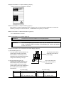
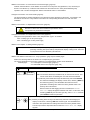
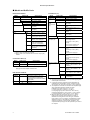
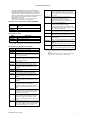
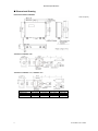
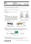
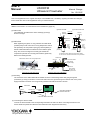
User’s Manual US300FM Ultrasonic Flowmeter Manual Change No. 15-010-E This is the supplement for the original manual (No. IM 01G05B03-01E, 1st Edition) regarding the added and changed items. Please also refer to this supplement when you read the manual. Addition to the section “3.5.4 Connection of the Transducers” (page 18) : (1) Cable Finish (b) Junction box side (a) Main unit side Unit : mm (2) Cable Gland Perform soldering Shield line Brown (*) White 12±2 When tightening the gland, not only pull back the cable shield (meshed part) but also roll it out into a ring-shaped form and let Cable shield (meshed) it be pushed by the compression part (grey-colored plastic) so that the cable shield will have electrical contact with the gland Less than 10mm Thin lines (**) 10±3 7±2 Perform soldering 52±5 60±5 13±3 7±2 shown in the right. White Shield line Brown (*) 12±2 The cable finish should be done as the drawings (a) and (b) Less than 5mm Cable shield (meshed) Thin lines (**) body. Also, be sure to align the convexity part outside the compression part and the concavity part inside the gland body. (*) Finish the brown cables as well as white cables. (**) You do not connect the thin lines to any terminals. Refer to the drawings below. Gland body Cap nut Cable shield rolled out into a ring-shaped form Outer skin of the cable Cable shield (ringed-shape) Signal lines Rubber ring Compression part (convexity part outside) Compression part Gland body (concavity part inside) Components of the cable gland Outer wall of the main unit or junction box Cutaway view of the cable gland (3) Grounding The connection of the cable shield will be realized as shown in the drawing below after going through the procedures (1) and (2) in the above. Connect the main unit to the ground through the terminal “PE” of the power supply terminals in the main unit. The grounding resistance should be less than 100 ohm. Transducers Sensors Junction box Connection cable Main unit Grounding resistance less than 100 ohm GND Connection of the cable shield (4) Connecting the Sensor ROMs Connect the sensor ROMs to the corresponding terminals in the main unit when connecting transducers. The sensor ROMs are packed and affixed to the transducers when shipped from the factory. Manual Change for IM 01G05B03-01E 1st Edition : No.15-010-E Yokogawa Electric Corporation July 30 2015-00 Changes to the section “3.1 Scope of Delivery” (page 11) : Change the figure of a nameplate to as below. Addition to the section “3.1 Scope of Delivery” (page 11) : When ordering a couplant weatherproof type (by couplant code “R” in the transducer specification or model code USPA097), a package of “Shin-Etsu Silicone, 1 COMPONENT RTV (KE45T)” is delivered. Addition to the section “3.3 General Precautions” (page 12) : ・Do not disassemble or remodel. Addition to the section “3.5.1 Location” (page 13) : Attention! The instrument must not be installed in a corrosive atmosphere. Attention! Use Submersible(IP68) type transducers when they are installed where condensation occurs. A Tokuchu request is necessary for Submersible type. However the diameter must be over 100 mm. Changes to the section “3.5.5 Connection to the Power Supply” (page 20) : (1) Terminal Block (page 19) The outer shapes of the terminal block for power supply connection, the printed The terminal names are the PE N(-) L(+) terminal names, and the design on the same both for AC and DC power supply. board below the terminal block have been changed as the drawing in the right. KL3 (2) Terminal Assignment (page 21) This can be used as the Regarding the terminal assignment, the earth terminal instead of terminal names were revised as below the terminal “PE”. from the original manual. The needed power supply is given in the nameplate on the housing, not in the plate below the terminal block. Terminal PE N(-) L(+) AC power supply Connection Earth Neutral Phase 100...230 V AC±10% DC power supply Terminal Connection PE N(-) L(+) (Earth) - DC + DC 24V DC±10% Manual Change for IM 01G05B03-01E 1st Edition : No.15-010-E July 30 2015-00 Addition to the section “3.5.5 Connection to the Power Supply” (page 20) : Install an external switch or circuit breaker as a means to turn the power off (capacitance; 15A, conforming to IEC947-1 and IEC947-3). Locate this switch either near the instrument or in other places facilitating easy operation. Affix a “Power Off Equipment” label to this external switch or circuit breaker. Changes to the section “3.6 Sensor ROM” (page 22) : The sensor ROMs are packed and affixed to the transducers when shipped from the factory, not inserted to the terminals in the main unit. They shall be connected to the corresponding terminals in the main unit when installation. Addition to the section “3.7 Replacement of the Fuse” (page 22) : Be sure to use the fuse which satisfies the specification below. Components may otherwise be damaged. Changes to the section “3.7 Replacement of the Fuse” (page 22) : Change the fuse specification “250V 1.25A, delayed action Type T” to as below. “250V 1A delay type” for AC power supply “250V 1.6A delay type” for DC power supply Addition to the chapter “4. Getting Started” (page 23) : Attention! The current outputs may temporarily turn unstable during the power-on sequence (including re-starting after power failure) and parameter display / setting mode. Take care of your process not to be affected by this behavior. Addition and deletion to the section “4.1.1 Key Operations” (page 23) and related pages : Refer to the following table for the function of corresponding key operations. The correct explanations for these key operations in the related pages are also as the table below. Related pages: “4.1.1 Interruption of Power Supply” (page 27) “15.2 US300FM doesn’t react anymore” (page 106) Switches the background lighting ON/OFF. LIGHT BRK INIT RESET ENTER [Operation during the measurement or menu display] RESET: Press these three keys simultaneously to recover from an error. This has the same effect as restarting the unit. Data will not be affected. INIT (cold start): Press these three keys simultaneously and release ENTER first. After acknowledging the display of main menu, release (i) BRK key first and then (ii) C key. This will initialize the instrument. Most parameters and settings are reset to the factory default values. The memory will not be cleared. Note that when the data logging function is activated, the DELETE MEAS.VAL. display will appear instead of main menu. In this case, after releasing (i) BRK key first and then (ii) C key, select NO or YES and then press ENTER to finish the procedure. [Operation when powering the instrument on] BRK INIT INIT (coldstart): Pressing these two keys simultaneously and after acknowledging the display of main menu, release (i) BRK first and then (ii) C. This will initialize the instrument. Most parameters and settings are reset to the factory default values. The same procedure is required as above when the DELETE MEAS.VAL. display appears. Manual Change for IM 01G05B03-01E 1st Edition : No.15-010-E July 30 2015-00 Addition to the section “4.4.1 Interruption of Power Supply” (page 27) : Attention! The current outputs may temporarily turn unstable during the power-on sequence after power failure. Take care of your process not to be affected by this behavior. Addition to the chapter “5. Basic Measurement” (page 29) : Note! When changing any settings in "PARAMETER" program branch, be sure to also go through "MEASURING" program branch to the end where the measurement will start. In this case, you do not always have to fix the transducers on to the pipe, and thus you do not always need to get the actual flow measurement. If you shut off the power supply without taking this procedure, the settings to be changed would not be effective and keep the same settings as before. Addition to the section “5.4 Selection of the Sound Path Factor” (page 34) : When the pipe outer diameter is more than 600mm, the sound path factor as “1” (one) is recommended. Otherwise, the measurement may become unstable when flow velocity or fluid temperature changed. Addition to the section “5.5.2 Mounting of the Transducers” (page 35) : The pipe wall thickness may slightly vary from part to part. Check it in advance by applying a wall thickness probe or some other ways and avoid mounting the transducers on such parts. Attention! Instructions for using “Acoustic couplant weatherproof type” (Shin-Etsu Silicone, 1 COMPONENT RTV) are as below. The operating condition of ambient temperature Before and during curing : 0 to +50°C / 32 to 122°F After curing : -40 to +180°C / -40 to 356°F When applying this couplant, cut the tip of attached nozzle to appropriate length and set it to the tube container. Also, remove matters like dust or oil on the surface to be applied. Otherwise, its adhesion force may become lower. When curing this couplant, keep the ambient and installation position temperature between 0 to +50°C (32 to 122°F). If not, the flow measurement may fail because of air bubbles formed inside the rubber before curing, etc. It usually takes one to three days for complete curing depending on the conditions. Addition to the section “5.5.2.2 Mounting with Fixtures and Chains” (page 36) : Attention! When using mounting fixtures, there may arise some air gap between the transducer surface and pipe wall because of any distortion of the pipe wall. Make sure to avoid having such air gap between them. Addition to the section “6.1 Selection of the Physical Quantity and of the Unit of Measurement” (page 39) : Attention! In case of mass flow, select “Other Medium” as a measured fluid. When “Other Medium” has been selected, US300FM requests to enter the density which is used to calculate mass flow. Manual Change for IM 01G05B03-01E 1st Edition : No.15-010-E July 30 2015-00 Changes to the section “7.2 Flow Totalizers” (page 43) : Two of the key operations have been changed as below, requiring pressing the keys “three times” . To reset the two flow totalizers to zero: OON three times when a totalizer is displayed. Press key To deactivate flow totalizing: Press key OOFF three times when a totalizer is displayed. Addition to the section “14.5 Activation of a Pulse Output” (page 95) : Maximum pulse output rate is 2 pulse per second (+/-20%). Set the “Pulse Value” and the “Pulse Width” so that the actual maximum flow in the pipe is less than half the displayed value (“Max – Value”). Example: 3 The actual maximum flow 120m /h Pulse Value = 0.02m 3 Pulse Width = 150ms INFO: Max – Value 3 240.0m /h Attention! OON It is necessary to activate flow totalizers by pressing key to get the actual pulse output. Refer to the section 7.2 (page 43) for flow totalizers. Changes to the chapter “A Standard Specification” (page 109 to 116) : Please use the following sheets for this chapter. Manual Change for IM 01G05B03-01E 1st Edition : No.15-010-E July 30 2015-00 Standard Specifications A Standard Specifications US300FM General Fluid: Liquid (Turbidity < 10,000 mg/L, Sound velocity 800 to 3,500 m/s, Temperature –30 to +200°C / –22 to +392°F) Measured Quantities: Volume flow, mass flow (by setting density), flow velocity, sound velocity in the fluid Measuring Principal: Transit time method using ultrasonic signal Pipe Sizes: 25 to 6,500 mm (1 to 255 inches) (covered by three types of transducers) Pipe and Lining Materials: Carbon steel, Stainless steel, Grey cast iron, Ductile iron, Copper, Glass, PVC, etc. Flow Velocity Range: ±0.01 to ±25 m/s (±0.033 to ±82 ft/s) Resolution: 0.025 cm/s (0.01 in/s) Repeatability: 0.15% of reading ±0.01 m/s (0.033 ft/s) Accuracy: (Note) Under fully developed rotationally symmetrical flow profile Volumetric flow: ±1 to 3% of reading ±0.01 m/s (0.033 ft/s) depending on pipe geometry and accuracy of entered pipe dimensions. Flow velocity: ±0.5% of reading ±0.01 m/s (0.033 ft/s) over sonic path Measuring Input : One or two (dual) (Channel A, Channel B). Current Output: One or two Range 4 to 20 mA (Load resistance 0 to 500 Ω) Note: The current outputs may temporarily turn unstable during the power-on sequence (including restarting after power failure) and parameter display / setting mode. Take care of your process not to be affected by this behavior. Frequency Output: None (standard), or one (optional) Range 0 to 1 kHz Contact type: Open-collector, 24 V / 4 mA Binary Output: None (standard), one, or two (optional) Contact type: Open-collector, 24 V / 4 mA Input / Output Terminal Configuration: Screw-type pillar terminals LCD Display: 2 line x 16 character LCD display with backlight. Configurable to display two measured values (e.g., flow rate and total flow) simultaneously, or to display values from optional dual input channels alternately. Keyboard: 15 keys (numerical, functional, or both) including four arrow-shaped keys for cursor operation, enabling easy access through its interactive menu structure. Display Language: Czech, Danish, Dutch, English (default), French, German, Norwegian, Polish, Turkey Measuring Cycle: 100 to 1000 Hz (per one channel) Flow Measurement: Flow velocity, Volume flow, Mass flow Straight Pipe Run in the Upstream: 10 to 50 pipe diameters, depending on the kind of flow disturbances Sound Velocity / Signal Amplitude Measurement (Online): Sound velocity and signal amplitude in the fluid available on-line simultaneously with flow measurement. Ultrasonic Flowmeter, Main Unit Housing Material: Aluminum Painting: Front cover: Deep sea moss green, Polyuretane and acrylic resin corrosion-resistance waterbased coating Back cover: Agate grey, Polyester resin corrosionresistance powder coating Totalization Function: Totalizes the volume flow or mass flow. Ten-digit number for both forward/reverse directions of each channel. Damping Function: Time constant 0 to 100 seconds, moving average. Sound Velocity Measurement (Off-line): Measures the sound velocity of unknown fluid starting from its estimated sound velocity. The result can be transferred to the current fluid parameter. Degrees of Protection: IP65 (EN60529) Mounting Method: Wall mounting Pipe mounting fixture (for 2-inch pipe, optional) IM 01G05B03-01E 1st Edition 1 Standard Specifications Arithmetic Operation on Optional Dual-Channel / Dual-Path Inputs: Arithmetic operations get the outcomes for calculation channel Y and Z by taking sum, average, or difference of two flow values from input channel A and B. Taking absolute values of each input independently in the calculation is also possible. Note: Two sets of transducers are necessary. Pulse Output (optional): Available via optional binary outputs. Pulse value: 0.01 to 1000 of totalization unit Pulse width: 100 to 1000 ms (±20%) Maximum output rate: 2pps (pulse/second) ±20% Alarm Output (optional): Available via optional binary outputs where each alarm item is assigned one-to-one. Alarm properties are also selectable for each alarm one-by-one. Alarm items: High limit, Low limit, Flow direction change, Quantity limit (for batch operation), and Error (measurement impossible) Alarm properties: Normal open / Normal close, Nonhold / Hold (at the alarm detection) Output Signal Configuration: Freely configurable including independent dual flow value outputs. Current / frequency outputs: Flow velocity, Volume flow, Mass flow, Sound velocity, or Signal amplitude Binary outputs: Pulse or Alarm Data Logging Function: Data storage capacity of 27,000 values. Storage rate is selectable from 1 s, 10 s, 1 min, 10 min, 30 min, 1h, or any other rate between 1 s to 43200 s (12 h) by the second. For each period of measurement, stored values are grouped by a user-defined measuring point name. Stored values can be transferred to a personal computer via RS232 serial communication port. (Note) As the RS232 port is on the front panel inside housing, use this function only for test / service / maintenance purposes. Communication Function: Transfers the measured values to a personal computer or a serial printer. Both on-line/off-line transfer during/after the measurement available. Output item: Flow value (flow velocity, volume flow, or mass flow), Totalization (forward, reverse), Sound velocity, Signal amplitude Output format setting: Spacing (for printer), Decimal point character, Data delimiter Communication interface: RS232 Communication port: D-sub 9-pin, male (Note) As the RS232 port is on the front panel inside housing, use this function only for test / service / maintenance purposes. Time-Programmable Measurement Function: Automatic start / stop of the measurement without human operation using internal clock for specific systems. Can be used with current output, binary output, data logging function, and/or communication function for recording the measurement. Site Parameters Storage Function: Eliminates the necessity of re-entering parameters for additional measurement on a site. Totally 80 sets of site parameters for pipe/fluid settings are available with user-defined site names. Material / Fluid List Customization Function: The lists of material / fluid in the parameter menu are editable. Unnecessary items can be cut off from the menu for user’s convenience. Registration of new material / fluid data is also possible totally up to 13 items with user-defined names. Power Supply: Power supply voltage: 100 to 230 VAC ±10% (50/60 Hz ±5% ) or 24 VDC ±10% Power consumption: Less than 15 W Safety and EMC Standard: General safety: EN61010-1:2010 EN61010-2-030:2010 Altitude at installation site: Max. 2000 m above sea level Overvoltage category: Overvoltage category II Pollution degree: Pollution degree 2 EMC regulation: EN61326-1:2006 Operating Conditions: Ambient temperature: –10 to +60°C (14 to 140°F) Ambient humidity: 0 to 95% RH or less (Non-condensation) Note: Lengthy operation at 80% or more is not recommended. Transducers Basic Construction: A set of transducers are composed of a pair of sensor elements (often called just as “transducers”), and transducer cables with a junction box at one end, which is to be connected to US300FM main unit by dedicated connection cable US300FC. The transducer cables are armed with stainless steel flexible tube. (Note) Fixing hardware (fixing strap, clips, etc.) and acoustic couplant are usually included in a set of transduces, specified in its model code by their kinds or with/without. Material: Case of sensor elements: Stainless steel EN/DIN 1.4571 (JIS SUS 316Ti, AISI 316Ti SS equivalent) Sensing surface of sensor elements: General temperature type: PEEK (Poly Ether Ether Keton) High temperature type: Polyimid Degrees of Protection: General type: IP65 (EN60529) Immersible type: IP67 (EN60529) Applicable Pipe Sizes (inner diameter): Medium type: 25 to 400 mm (1 to 16 inches) Lager type: 100 to 2,500 mm (4 to 98 inches) Very large type: 2,000 to 6,500 mm (78 to 255 inches) (Note) Only “6,500 mm” above is the size for outer diameter. 2 IM 01G05B03-01E 1st Edition Standard Specifications Fluid Temperature Range: General temperature type: –30 to +130°C (–22 to +266°F) High temperature type: –30 to +200°C (–22 to +392°F) Note: Pay attention also to temperature specification of the couplant you choose. Connection Cable Connection cable is always necessary to connect the transducers (junction box) and the US300FM main unit. The length is specifiable from 1 m (3 ft) to 300 m (984 ft) by the meter. Accessories Fixing Hardware, Couplant, etc: Specified in the suffix code of US300FM/US300FT. Model codes as accessories also available for separate/additional orders (listed later). Displaying Data in Graph: Display measured data of selected measuring data set in graphic format. Marker type and color for each line of values selectable. Scales for time-axis and value-axis can be changed from default condition of automatic scaling. Graph printing function embedded. Displaying Statistical Data: Display statistical data of the measurement. Total data points, minimum, maximum, average and standard deviation of the measured data can be shown. Data range for statistical processing can be designated if necessary. Exporting Text File: Parameter record and measured data can be exported to a text file. Options for exporting items or their formats are available. Entering Remarks: User’s remarks for each measured data can be entered and edited in the transferred data file on a personal computer. Remarks can be displayed in the main window of the software. Data Transfer Software General: The software installed on a personal computer receives one or more records of logging data and parameter sets stored in US300FM main unit via RS232 communication port. Data can be viewed or graphed on a PC monitor, or exported as a text file. This software works while US300FM is off-line (not measuring flow) where current output goes down to zero. Function: Displaying Parameter Record: Display parameter record of selected measuring data set. Displaying Measured Data in Table: Display measured data of selected measuring data set in table format. Display Language: English, German (Note) Help is available only in English. Operating Environment: Personal Computer: Microsoft® Windows® hardware compatible, one or more RS232 port Operating System: Microsoft® Windows® 98, ME, NT, 2000, XP Standard Accessories: RS232 cable, RS232 adapter 9/25 * Microsoft® and Windows® are registered trademarks of Microsoft Corporation in the United States and/or other countries. Units of Measurement Volume flow Flow velocity m3/h m/s m3/min inch/s Mass flow g/s Totalizers Volume Mass m3 g t/h l kg m3/s kg/h gal t l/h kg/min Sound velocity m/s l/min l/s USgph USgpm USgps bbl/d bbl/h bbl/m 1 gallon [US] = 3.78 l; 1 barrel = 42 gallons = 158.76 l IM 01G05B03-01E 1st Edition 3 Standard Specifications Model and Suffix Code Ultrasonic flowmeter Transducers (*3) Model US300FM Model Suffix code Specification US300FT ·························· Transducers for fixed type Usage (*4) -G ····················· General purpose (IP65) -W ···················· Waterproof (IP67) Suffix code Specification ····························· Ultrasonic flowmeter -A1 ······················ -A2 ······················ 1 ··················· Power Supply 4 ··················· -1 ················ Input Channel Output -2 ················ Electrical connection Option -4 ··········· /PU1 ···· /PU2 ···· /FQ1 ···· /BGT ···· /SCT ···· /PMT ···· One current output Two current outputs 100 to 230 V AC ±10% 24 V DC ±10% One input channel (one-path) Two input channels (dual-path) ISO M20 x 1.5, female One binary (pulse or alarm) output (open-collector) (*1) Two binary (pulse or alarm) outputs (open-collector) (*1) Frequency output (opencollector, 0 to 1 kHz) (*2) Tag number on nameplate (in the nameplate label, maximum 16 characters) Tag number on stainless steel tag plate (maximum 16 characters) Pipe mounting fixture *1: Option /PU1 and /PU2 are exclusive. *2: Option /FQ1 is not selectable for two current output (-A2) models Connection cable (*8) Model US300FC Length Suffix code Specification ···················· Connection cable -Gxxx ········· xxx: Cable length 001 to 300 [m] *8: Two sets of connection cables are necessary when applying dual channel/path measurement. Data transfer software Model Suffix code Specification US300SA ···················· Data transfer software (Windows version) Including connecting kit (RS232 cable for connection, RS232 adapter 9/25) Language -1 ················ English / German version 00 ······· Always 00 4 BG ················ Medium & General (with 3 m / Pipe Size / Fluid 9.8 ft cable) Temperature BH ················ Medium & High (with 3 m / 9.8 ft (*5) cable) CG ················ Large & General (with 4.4 m / 14.4 ft cable) CH ················ Large & High (with 4.4 m / 14.4 ft cable) DG ················ Very large & General (with 12 m / 39.4 ft cable) -N ·············· Always N Fixing band, strap B ············ For 25 to 1,400 mm (1 to 55 in.) and clips (*6) Two fixing bands One strap of 10 m (32 ft) length Two clips of medium type Two clips of large type C ············ For 1,400 to 2,800 mm (55 to 110 in.) One strap of 20 m (65 ft ) length Two clips of large type D ············ For 2,800 to 6,500 mm (110 to 255 in.) Two straps of 20 m (65 ft) length Two clips of large type N ············ None G ········· General temperature type (nonAcoustic couplant (*7) adhesive, –30 to +130°C / –22 to +266°F) H ········· High temperature type (nonadhesive, –30 to +200°C / –22 to +392°F) R ········· Weatherproof type (adhesive, –40 to +180°C / –40 to +356°F) Option N ········· None /TTP ··· Transducer tag plate (maximum 16 characters) *3: Two sets of transducers are necessary when applying dual channel/path measurement. *4: A Tokuchu request is necessary when transducers are installed where condensation occurs. However the pipe size must be over 100 mm (Large type or Very large type). *5: The alphabetic characters in the suffix code represent pipe sizes and fluid temperature ranges are below. B: Medium type (25 to 400 mm / 1 to 16 in.) C: Large type (100 to 2,500 mm / 4 to 98 in.) D: Very large type (2,000 to 6,500 mm / 78 to 255 in.) G: General temperature (–30 to +130°C / –22 to +266°F) H: High temperature (–30 to +200°C / –22 to +392°F) *6: When the pipe size is less than 50 mm (2 in.), select N(None) here first and order separately one each of USPA053 mounting fixture short ruler type, USPA036 fixing chains (0.5 m/1.6 ft length), and USPA097 couplant weatherproof type. It will avoid any stress that could be caused by expansion of the pipe after installation. The couplant weatherproof type can be specified by the code R for couplant. IM 01G05B03-01E 1st Edition Standard Specifications *7: The couplant weatherproof type is recommended for permanent installation in the outdoor, etc. It is adhesive liquefied rubber and tight contacts between transducers and pipe surface can be obtained by curing it. It usually takes one to three days for complete curing depending on the conditions. The operating condition of ambient temperature is as below. Before and during curing : 0 to +50°C / 32 to 122°F After curing : –40 to +180°C / –40 to 356°F Accessories (for ultrasonic flowmeter US300FM) Model USPA201 USPA221 USPA231 Description Pipe mounting fixture(to add the option /PMT) Blind plug for cable gland port Cable gland Accessories (others) Model USPA401 USPA402 USPA411 Description RS232 cable (*9) RS232 adapter 9/25 (*9) Measuring tape *9: Included in data transfer software US300SA as standard. Accessories (for transducers US300FT) Model Description USPA001 Fixing strap (10 m / 32 ft length) USPA002 Fixing strap (20 m / 65 ft length) USPA011 Fixing clips (medium type, for pipe size 40 to 100 mm / 1.5 to 4 in., set of two clips) USPA012 Fixing clips (large type, for pipe size 100 to 6500 mm / 4 to 255 in., set of two clips) USPA021 Fixing bands (only for pipe size 25 to 50 mm / 1 to 2 in.) USPA032 Fixing chains (set of two extensible chains) (2 m / 6.5 ft length, equal to 600 mm / 23 in. diameter) USPA033 Repair set for fixing chains USPA034 Retaining clips (set of two clips, used with fixing chains) USPA036 Fixing chains (set of two extensible chains) (0.5 m / 1.6 ft length, equal to 150 mm / 5.9 in. diameter) USPA037 Fixing chains (set of two extensible chains) (1 m / 3.2 ft length, equal to 300 mm / 11.8 in. diameter) USPA053 Mounting fixture short ruler type (for transducers medium pipe size type, temperature range –30 to +200°C / –22 to +392°F, set of two blocks with 120 mm / 4.7 in. ruler) USPA054 Mounting fixture standard type (for transducers medium pipe size type, temperature range –30 to +200°C / -22 to +392°F, set of two blocks with 330 mm / 13 in. ruler) USPA055 Mounting fixture magnetic general temperature type (for transducers medium pipe size type, temperature range –30 to +100°C / –22 to +212°F, set of two blocks with 330 mm / 13 in. ruler) USPA057 Mounting fixture standard type (for transducers large or very large pipe size type, temperature range –30 to +200°C / –22 to +392°F, set of two blocks with 330 mm / 13 in. ruler) IM 01G05B03-01E 1st Edition USPA058 Mounting fixture magnetic general temperature type (for transducers large or very large pipe size type, temperature range –30 to +100°C / –22 to +212°F, set of two blocks with 330 mm / 13 in. ruler) USPA073 Additional magnets for mounting fixture magnetic general temperature type (for transducers medium pipe size type, temperature range –30 to +100°C / –22 to +212°F, set of two magnets) USPA075 Additional magnets for mounting fixture magnetic general temperature type (for transducers large or very large pipe size type, temperature range –30 to +100°C / –22 to +212°F, set of two magnets) USPA081 Ruler for mounting fixture (marked length 120 mm, equivalent to 4.7 in.) USPA082 Ruler for mounting fixture (marked length 330 mm, equivalent to 13 in.) USPA091 Acoustic couplant general temperature type (non-adhesive) (100 g, –30 to +130°C) (0.22 lb, –22 to +266°F) USPA092 Acoustic couplant high temperature type (nonadhesive) (100 g, –30 to +200°C) (0.22 lb, –22 to +392°F) USPA097 Acoustic couplant weatherproof type (adhesive) (*10) (100 g, –40 to +180°C) (0.22 lb, –40 to +356°F) *10: The operating condition of ambient temperature is as below. Before and during curing : 0 to +50°C / 32 to 122°F After curing : –40 to +180°C / –40 to 356°F 5 Standard Specifications Dimensional Drawing Ultrasonic flowmeter US300FM Unit: mm (inch) Transducers US300FT-□B□ Transducers US300FT-□C□, US300FT-□D□ Transducers US300FT-□B□ US300FT-□C□ US300FT-□D□ 6 X m (inch) 2.0 ( 78.7) 2.0 ( 78.7) 5.0 (196.9) Y m (inch) 1.0 ( 39.4) 2.4 ( 94.5) 7.0 (275.6) X+Y m (inch) 3.0 (118.1) 4.4 (173.2) 12.0 (472.4) Weight kg (lb) 0.9 (1.98) 1.5 (3.31) 2.5 (5.51) IM 01G05B03-01E 1st Edition Standard Specifications Connection Cable US300FC Wirings Terminal Layout Cable Connection Terminal Designations Terminal Name AV AVS AR ARS BV BVS BR BRS SA1 SA2 SA3 SA4 SB1 SB2 SB3 SB4 Description Downstream transducer signal for channel A Upstream transducer signal for channel A Downstream transducer signal for channel B Upstream transducer signal for channel B Sensor ROM for channel A Sensor ROM for channel B Terminal Name P1+ P1P2+ P2P3+ P3P5a P5b P6a P6b PE N(-) L(+) Earth Neutral AC power supply (100 to 230 V AC ±10%) *1 PE N(-) L(+) (Earth) DC– DC+ (24 V DC ±10%) *1 Description Current output (+,–) Current output (+,–) when specifying "two current outputs" Frequency output (+,–)(optional) Binary (pulse or alarm) output (optional) Same as above *1: Either of these according to specified power supply specification. IM 01G05B03-01E 1st Edition 7