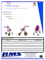
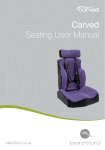
1
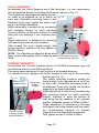
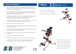
EDITION FOUR April 2014 CONTENTS Introduction …………………..….…2 Pelvic Belt ...…………………….…11 Safety Guidelines …….………….3 Accessories: Initial Installation…....…4,5,6 & 7 Knee block and Sacral Pad…12 Adjustments: Pommel..…………………..………..12 Seat Base………………………….. 8 Anklesures………….…….…...…..13 Backrest …………………....……….8 Tray……………………….….………13 Foot Support………...………….….9 Upholstery…………….………..….14 Footstraps ………………………….9 Transportation……..………..……15 Headrest……………..….……… . ..9 Additional Transport Info...16-18 Pelvic Supports……………...…..10 Product Maintenance….………18 Thoracic Supports………….…..10 Warranty Statement……….…..19 Serial Number & Inspection Record ………….. Back Page INTRODUCTION RMS Ltd would like to take this opportunity of thanking you for choosing the new lightweight Gill III Junior Supportive Seating System, which we are confident, when used in conjunction with one of the recommended surrogate bases listed below, will suitably meet the requirements of the user for which it was prescribed. From the time of its initial conception, the Gill III Junior has undergone rigorous strength testing and quality inspections, including the successful “Crash Testing” to ISO 16840-4, at the Millbrook Proving Ground on 7th July 2006. The Gill III Junior Seating System, is available in two sizes, both of which have been designed to be used in conjunction with one of the following wheel-bases, by utilising the surrogate base manufacturer’s seat shell interface:The Otto Bock “Kimba” (all models), “Discovery” (36cm) and “Skippi” Power-base, also the “Tom Cross” (size 2) by Activate. All of these are suitable for transportation of the occupant in a motor vehicle when used in conjunction with the appropriate transportation restraint systems. The “Bingo” Rehab Pushchair by Hoggi will also accept the Gill III Junior but this combination is currently NOT recommended for transportation of the occupant in a motor vehicle. Only use the Gill III Junior as instructed in this Manual, together with any instructions supplied by the wheel-base manufacturer. Should the reader have any concerns regarding the installation, or use of the Gill III Junior, please contact the RMS Ltd Technical Help Line on 01795 477280. RMS Ltd reserves the right to change, without notice, the design, the methods of manufacture, or any materials used in the construction of the Gill III Junior Seating System, where it considers such changes will serve to improve the product quality, or become necessary to meet any changes in legislation affecting the device. Page 2 SAFETY GUIDELINES IMPORTANT NOTES: Due to the various activities that a wheelchair user has to perform, RMS recommends that, prior to issuing the Gill III Junior and the wheel-base into which it is to be interfaced, this User Manual, together with any User Guide issued by the wheel-base manufacturer, should be studied by all relevant persons to ensure that the instructions, procedures and warnings are clearly understood and carefully observed. For correct support and user comfort, it is strongly recommended that the initial installation and adjustments are carried out by a suitably qualified person. The maximum occupant capacity of the GILL III Junior, for transportation purposes, is 28Kg (4.4 stones), when interfaced onto one of the wheelbases listed on page 2. After the GILL III Junior has been initially adjusted to suit the individual user, any settings should not be subsequently affected by the removal and refitting of the GILL III Junior to allow the mobility-base to be folded. However, care should be taken to avoid impacting adjustable components whilst the Seat is removed from the wheel-base as this could affect their original pre-set position. To accommodate any changes in user growth or postural positioning, it is recommended that the user be checked at regular intervals, by a suitably qualified person, to ensure that adjustable components are correctly set to suit the user’s current requirements. Carers should ensure correct utilisation of any positioning Straps or Harnesses, as failure to do so could result in injury to the user. It is recommended that any postural Straps or Harnesses being used, are the first items to be secured when the user enters the seat and the last items to be released before exiting. Worn or damaged upholstery can lead to hygiene contamination, cause injury to the user and, in some cases, fail to support the user correctly. Regular inspections of all upholstery should be made and any defects should be reported to the relevant authority for rectification as soon as possible. Ancillary devices, such as the Headrest, positioning Straps and Harnesses, Kneeblock or Pommel should be checked for security on a daily basis. The parking brakes of the mobility-base should always be applied before attempting to transfer the occupant, removing or refitting the Gill III Junior or making any adjustments. Never suspend heavy objects from the Gill III Junior, or any part of the wheel-base which is not designated or intended for the purpose of carrying goods, as this could seriously affect the overall stability. NOTE: See also details on Transportation pages 15-18 Page 3 INITIAL INSTALLATION Where the Gill III Junior is not factory fitted by RMS to the intended wheel-base, the information on this page and page 5, together with the relevant installation instructions detailed on pages 6 and 7, should be carefully followed. The Seat Base Panel of both sizes of Gill III Junior, are drilled to accept the corresponding size of wheel-base manufacturers seat shell interface. The installer should ensure that the correct parts are to hand before proceeding further, see table below :Gill III Junior Size Wheel-base Make/ Model Interface Adapter & Seat Shell Interface Size Use Manufacturer’s Part Number 1 Otto Bock - Discovery 36cm 36cm Parallel Adapter HR32048200 with Interface HR32046700 36cm 1 Otto Bock - Kimba range Size 1 Size 1 Interface HR32046700 1 Activate -TOM Maxi Chassis Size 2 p/n 410209GIL Standard Interface p/n 410078S 1 Hoggi - Bingo size 1 1 Trapezium Size 1 3201-2120E 2 Otto Bock Discovery 36cm 36cm Parallel Adapter HR32048200 with Interface HR32046700 36cm 2 Otto Bock Kimba range Size 1 Size 1 Interface HR32046700 2 Otto Bock Kimba range Size 2 Size 2 HR32046800 2 Otto Bock Skippy 2 HR32046800 With RMS adaptor 2 Hoggi - Bingo Size 2 2 Trapezium Size 2 3203-2120E 2 Activate - TOM Maxi Chassis (Size 2) p/n 410209CSI Standard Interface p/n 410078S TOM CROSS DISCOVERY KIMBA BINGO Page 4 INTERFACE MOUNTING POSITIONS INTERFACE ATTACHMENT POINTS SEAT BASE Size 2 INTERFACE ATTACHMENT POINTS SEAT BASE Size 1 Seat Shell Interface Mounting Code = Otto Bock/Horocek size 2 = Tom Cross size 2 = Hoggie Bingo size 2 FRONT Fig. 1 Seat Shell Interface Mounting Code = Otto Bock/Horocek size 1 = Tom Cross size 2 = Hoggie Bingo size 1 Fig. 2 FRONT ATTACHING the GILL III Junior to the WHEEL-BASE MANUFACTURER’S SEAT SHELL INTERFACE . (A clean, clear work surface should be allocated for this operation) SUGGESTED TOOL REQUIREMENTS:⅜″ Drive Ratchet and 6″ Extension. ⅜″ Drive 10mm socket. ⅜″ Drive 8mm socket. 0 - 20 ft/lbs ⅜″ Drive Torque Wrench. M4 Hexagon Key. M3 Hexagon Key. Pozi-drive size 2 screwdriver Small Rubber Hammer. Cordless Drill with 6mm drill bit. NOTE: A Hacksaw and access to a Vice will be required for the Tom Cross application. To enable the intended wheel-base seat shell interface to be attached to the Gill III Junior, the new seat unit is supplied with two fitting kits (A & B) :Kit A is for use with the Discovery/ Kimba/ Skippi and Tom Cross wheel-bases. Kit B is for use with the Hoggi—Bingo wheelbase only. Each fitting kit will contain the appropriate screws, washers, nuts, spacers and blanking plugs to suit each application. Page 5 Otto Bock—Discovery/Kimba and Skippi Refer to Figs. 1 & 2, on page 5 to locate the models. ate pre-drilled mounting points, Refer toin Figs. marked BLUE.1&2 to locate the correct pre-drilled mounting positions, RED. Use Kit A for this installation. marked Attachin the Activate interface to the underside of the Gill III Junior Seat Base Prior by to inserting commencing installation, it will bescrews necessary to remove Seat 4—M6x45 countersunk through the Seatthe Base Cushion from the Gill III Junior Seat Base. from the upper face, then installing a 28mm long PVC spacer bush onto To allow sufficient clearance each screw, before locating the screws through the interface panel.between Fig. 3 the Footrest Support Panel and the interInstall one plain washer and one M6 Nylock Nut onto each screw. face release catch, it may be necessary on size one models, to slacken the catch lever bolt, to allow the lever to be turned 90º, to a downward pointing position. Re-tighten catch lever securing nut to 5ft/ lbs (6.8Nm). Attach the appropriate Otto Bock seat shell interface (see application list page 4) to the underside of the Gill III Junior Seat Base (release catch at front), by inserting 4—M6x45 countersunk screws through the Seat Base from the upper surface, then installing one 28mm PVC spacer bush onto each screw, before locating the screws through the holes in interface panel, (see Fig. 3) Install one plain washer and one M6 Nylock Nut onto each screw. Tighten each M6 Nylock Nut to 5ft/lbs (6.8Nm). Tom Cross size 2 models only IMPORTANT NOTE: To enable the Tom Cross wheel-base to accept the Gill III Junior seat unit, it will be necessary to remove a section of frame from the front of the manufacturers seat shell interface. Fig. 5 Fig. 4 Whilst there are two sizes of 38mm interface available for the Tom Cross wheel-base, the Gill III Junior seat base is only predrilled to accept the smaller Cut just below size 1. (See Fig. 4) threaded lugs Drill out to 6mm Measure and mark a distance of 38mm (1½”) up from the front cross bar just below the threaded lugs, (see Fig. 5). After removal of the unwanted frame section, de-burr exposed holes in the seat shell interface frame and install blanking plugs supplied in Kit A. Increase the four holes as indicated in Fig. 5 from 5mm to 6mm dia. Prior to commencing attachment of the seat shell interface, it will also be necessary to remove the Seat Cushion from the Gill III Junior Seat Base. [cont] Page 6 Refer to Figs. 1&2 to locate the correct pre-drilled mounting positions, marked in BLUE. Use Kit A for this installation. Attach the prepared Tom Cross seat shell interface to the underside of the Fig. 6 Gill III Junior Seat Base (release catch levers towards the front), by inserting 4M6x60 countersunk screws through the Seat Base from the upper surface, then installing one 28mm PVC spacer bush onto each screw, before locating the screws through the holes in interface panel. Install one plain washer and one M6 Domed Nylock Nut onto each screw. Tighten each M6 Nut to Tighten the M6 Nylock Nuts to 5ft/lbs (6.8Nm). Hoggi—Bingo Refer to Figs. 1&2 to locate the correct pre-drilled mounting positions, marked in GREEN. Use Kit B for this installation. Prior to commencing installation, it will be necessary to remove the Seat Cushion Fig. 7 Size 1 shown from the Gill III Junior Seat Base. Attach the appropriate Bingo seat shell interface (see application list on page 4) to the underside of the Gill III Junior Seat Base (widest end of interface to the front), by inserting the 4-M6x45 countersunk screws through the interface from the underside. Then install a 28mm spacer onto each screw (counter-bored end away from the interface). Secure each screw to the Seat Base by means of a brass “top-hat” type nut, that will locate into the appropriate holes in the Seat Base from the upper surface. Tighten each M6 Screw to 5ft/lbs (6.8Nm). Fig. 8 Brass “Top-Hat” Nuts NOTE: After attaching the appropriate interface, the Gill III Junior is ready to be placed onto the intended wheelbase. Apply the wheelbase parking brakes, prior to attaching the seat. Page 7 ADJUSTMENTS NOTE: All seat adjustments can be carried out with the Gill III Junior attached to the wheelbase. SEAT BASE (Depth Adjustment) Fig. 9 Seat depth adjustment is achieved Point B by moving the Backrest forwards or rearwards. Adjustment can be made at the connection blocks where the Backrest Braces join the Seat Base, (inset). Two adjustment areas are available, X Point A (see Fig. 9), the first being at point A, by removing both screws, nuts and washers W on each side. This will allow the Backrest to be moved rearwards to align Brace holes A with the holes in the connecting blocks. Refit screws, nuts and washW ers and re-tighten to 5ft/lbs (6.8Nm). The second adjustment area is on the Seat Base, by removing the two screws at point B on both sides this will allow the Backrest to be moved forwards or rearwards to obtain the required seat depth. There are four adjustment positions available on the size one Gill III Junior and six positions on the size two model. Refit screws after adjustments and fully tighten to 5ft/lbs (6.8Nm). NOTE: Ensure that any adjustments are carried out equally on each side. BACKREST (Height and Angle) There are four Backrest height positions available on both sizes of Gill III Junior. To raise or lower the Backrest panel, remove screws, washers and nuts Y (see Fig.10) from both sides and re-position Backrest as required. Refit screws, washers and nuts and re-tighten to 5ft/lbs (6.8Nm). There are also two angular positions for the Backrest, 90° and 95°. Adjustment can be made by slackening Z both domed Nylock nuts and screws Z (see Fig. 10) on both sides. The lower screw holes have a double-countersink which allows the screws to be positioned in either the forward 95º position or rearward 90º position. Y Set Backrest to the required position and re-tighten screws. Re-tighten Nylock nuts whilst holding the screws. NOTE: Ensure that any adjustments are carried out equally on each side. Fig. 10 Y Page 8 FOOTREST PANEL The Footrest Panel on both sizes of Gill III Junior is height adjustable. Fig. 3 To gain maximum adjustment, the Footrest Panel has three mounting holes, although only two of these are used at any one time, Fig. 11 normally positions 1 & 2 (see Fig. 11) as these will give maximum leg length. Using positions 2 & 3 will allow the Footrest Panel to be raised a further 25mm on size one seat units and 30mm on the size two. Height adjustment is made by slackening the two 1 A mounting screws A (Fig. 11) sufficient to allow the 2 3 Footrest Panel to slide up or down. Set Footrest to required height and retighten screws to 5ft/lbs (6.8Nm). To enable the Footrest Panel to be raised to the maximum height, remove the screw and key washer from position 1 and refit into position 3, (Fig. 11). Set Footrest Panel to required height and retighten screws to 5ft/lbs (6.8Nm). FOOTSTRAPS Fig. 12 Slots B To utilise the Footstraps, lift the cam locking levers on the ankle straps and pull strap free end through buckle. Insert each foot into a toe strap and route ankle strap over the instep and down into the buckle. Strap tension is adjusted by simply pulling the free end through the cam locking buckle and folding cam lever fully over, to secure Wider Fitting Positions Slots A the straps. The Footstraps are fitted as standard, to the inner slots A on the Footrest Panel (see Fig. 12). However, alternative slots are available B which allow the straps to be extended outwards by 25mm to suit changes in footwear, or for wider fitting users. The straps can be easily rerouted if required, by following the directional arrows in Fig. 12, but utilising the outer slots B instead of slots A. HEADREST The Headrest locates into a receiver socket which is attached to the upper area of the Backrest Panel and is height adjustable. To insert Headrest into the receiver, pull out the spring loaded locking pin (see Fig. 13) and insert Headrest stem. Release locking pin at the required height. Four positions are available. Fig. 13 Spring-loaded Locking Pin Page 9 PELVIC SUPPORTS As standard, the Pelvic Supports are of the fixed type, (i.e. non swing-away) and are attached directly to the Backrest Panel as shown in Fig. 14. The slotted mounting brackets enable the pelvic width to be adjusted by up to 50mm on Fig. 14 each side. Alternative mounting holes in the Backrest Panel also enable the pelvic supports to be height adjustable. Width adjustment is carried out by slackening Fixed type both retaining screws on each mounting Pelvic Support bracket sufficient to allow the bracket to slide along the key washers to the required position. Height adjustment is achieved by removing both securing screws and key washers. After locating the most suitable height, refit screws and key washers and fully tighten to 5ft/lbs (6.8Nm). NOTE: The Adjustments detailed above also apply where swing-away Pelvic Supports are Pelvic support mounting screws and key washers. fitted. THORACIC SUPPORTS As standard, the Thoracic Supports will be of the RMS swing-away type and are attached directly to the Backrest Panel. The swing-away mechanism is self-locking in the forward direction. To release the lock, depress the button located on the top of the mounting bracket (see Fig. 15) Fig. 15 The slotted mounting brackets enable the Positive lock Swing-away thoracic width to be adjusted by up to 50mm release Button on each side. Alternative mounting holes in Thoracic Support the Backrest Panel also enable the thoracic supports to be height adjustable. Width adjustment is carried out by slackening both retaining screws on each mounting bracket, sufficient to allow the bracket to slide along the key washers to the required position. Retighten screws to 5ft/lbs (6.8Nm). Height adjustment is achieved by removing the support mounting screws and key washers, re-positioning supports to required Thoracic support height and re-fit screws and key washers. mounting screws Fully tighten screws to 5ft/lbs (6.8Nm). and key washers. Page 10 Fig. 16 Tri-slot Belt or Harness Mounting Alternative lower fixing point for Pelvic Belt PELVIC BELT The Gill III Junior is supplied with a 25mm Pelvic Belt with comfort pads as standard . The Belt is attached to the seat unit via the Trislot mounting points located in the Backrest Braces, (see Fig. 16). Initial belt length adjustment should be made equally at these points. Final Belt adjustment can be made, after the main buckle has been connected, by pulling on the “D” rings located on either side of the main buckle. IMPORTANT NOTE: The Pelvic Belt supplied with the Gill III Junior MUST NEVER be used as the sole method of occupant restraint during transportation in a motor vehicle. (see NOTES section on transportation page 15) ACCESSORIES Fig. 17 HARNESSES Several styles of Harness, suitable for use with the Gill III Junior, are available from RMS Sales and can be viewed in the current RMS accessory catalogue. (RMS Shoulder Harness shown in Fig. 17). It is recommended that a Harness be installed and initially adjusted by a suitably qualified person and should always be used in conjunction with a correctly adjusted Pelvic Belt. Upper Harness fixing points are located on either side of the Headrest Mount. (see Fig. 18). Fig. 18 Lower fixings can be attached to the Backrest Braces, (see Fig. 16). Dependant on the direction of pull required on the Pelvic Belt or Harness, the installer may wish to use the Tri-slot positions for the Harness and the alternative fixing points for the Pelvic Belt. It will then be necessary to use the displaced Triplates from the Harness to attach the Pelvic Belt to the alternative fixing point (see Fig. 16). M6 x 20 dome head screws with washers and Nylock Nuts are required for attachment at this point. Upper Harness fixing points IMPORTANT NOTE: RMS Harnesses are intended to be used for postural positioning and individual security only. They MUST NEVER be used as the sole method of occupant restraint during transportation in a motor vehicle. (see NOTES section on transportation page 15) Page 11 KNEEBLOCK (Pop-Pin type from Serial No. 01294) To install the Kneeblock, depress forward release pin (a) on the underside of the horizontal stem (Fig.19) and insert stem into mounting through Footplate mounting panel until rear pin locates in locking hole. To remove Kneeblock, depress release pin (a) and slide Kneeblock assembly forward. Depth adjustment is made with the Kneeblock removed by repositioning the spring locking “PopPin” (a) along the series of holes in the underside of the horizontal stem. (A small screwdriver will assist Screw (b) with this operation). Height adjustment is made, by slackening screw (b), set Kneeblock to required height and re-tighten screw. NOTE: It is recommended that Footstraps are Release Pin (a) always used in conjunction with a Kneeblock. (See also NOTES regarding Kneeblocks being used during transportation page 15 ). SACRAL PAD Insert Sacral Pad Under Cushion Cover A Sacral Pad will be factory fitted, where a Kneeblock has been supplied with the Gill III Junior. Fig. 20 Where a Sacral Pad is supplied as part of a Kneeblock kit to be fitted to a Gill III Junior after leaving the factory, the following instructions should be implemented:Remove the Velcro attached Backrest Cushion. Unzip both sides of the Cushion Cover upwards from the bottom, sufficient to allow the Sacral Pad to be inserted under the covering fabric (see Fig. 20). Carefully re-zip the Cushion Cover and refit to Backrest. POMMEL To install the Pommel stem, depress forward release Fig. 21 pin (a) on the underside of the horizontal stem (Fig.21) and insert stem into mounting through Footplate mounting panel until rear pin locates in locking hole. To remove the Pommel, depress release pin (a) and slide Pommel assembly forward. Depth adjustment is made with the Pommel removed and by repositioning the spring locking “Pop-Pin” (a) along the series of holes in the underside of the horiScrew (b) zontal stem. (A small screwdriver will assist with this). The Pommel is also height adjustable, by slackening screw (b) located on the front face of the Pommel frame. Set to required height and retighten sufficient to Release Pin (a) prevent any movement. (See also NOTES regarding Pommels being used during transportation, page 15 ). Fig. 19 Page 12 ANKLESURES RMS “Anklesure” foot control devices are intended to assist with more severe unwanted foot movements. Part numbers AS001 (Tiny) and AS002 (Small) can be ordered directly from RMS Sales, on 01634 578881. Fig. 23 Fig. 22 Utilise pre-drilled holes for mounting bridges Utilise foot strap slots to attach mounting bridges. Anklesures can be easily installed onto the Gill III Junior Footrest Panels after removal of the original equipment Footstraps. With the Size 1 Gill III Junior, the Anklesure mounting bridges can be attached directly to the Footrest Panel (see Fig. 22) using the Footstrap slots. The Mounting Screws (supplied), should be inserted through the bridges from the top and secured on the underside of the Footrest Panel by means of a plain washer and M5 Nylock Nut (supplied). Tighten all nuts sufficient to prevent any movement. With the Size 2, the mounting bridges are fitted as above but utilising the rear Footstrap slots and the pre-drilled holes located between the front and rear slots, (see Fig. 23). For adjustment advice, please refer to the fitting guidelines supplied with the Anklesure devices. Fig. 24 TRAYS The Tray is designed specifically for Gill III Junior Seating Systems and offer the user a secure platform for feeding, playing or learning activities. Two sizes of Tray are available, one for each size of Gill III Junior. Attachment is via a receiver bracket fitted to the outer face of each Backrest Brace, (see Fig. 24). NOTE: With the Tray depth set to the closest position, it may be necessary to swing both Thoracic Pads outwards to install or remove the Tray. Return Pads to Support position after installation or removal. [cont] Page 13 Tilt Tray rearwards when inserting into the Receivers Two domed Nylock TRAYS [cont] Nuts located under Depth adjustment to suit the user, can be each side made on the underside of the Tray where the support stems attach to the Tray. (see Fig. 25). (A M10 spanner and size 2 Pozi-drive screwdriver will be required). To enable the Tray to be moved forwards or rearwards, slacken all four Domed Fig. 25 Nylock Nuts whilst holding the screws. Adjustments must be made equally on each side, before re-tightening Nylock Nuts just sufficient to prevent any movement between support stems and the Tray. The Tray is manufactured from black PVC with varnished hardwood up-stands. This allows the Tray surface to be washed or cleaned with all types of Hygienic wipes. (See also NOTE regarding use of Trays in transportation, page 15 ). UPHOLSTERY The Gill III Junior upholstery is finished in “Agua” Stretch high performance fabric, which is ideally suited for use in the Healthcare sectors. Available in six colours, “Agua” Stretch fabric is: Waterproof—Breathable—*Anti-Bacterial—*Anti-Fungal—Suitable for use with pressure distributing foam—**Fire Retardant—Wipe Clean —Colourfast to sunlight and very Stain Resistant to blood, urine, grease, ink, iodine, betadine, ketchup, chewing gum, chocolate, coffee and wine. *Anti-bacterial/Anti-fungal: will not support microbial or fungal growth, including Salmonella, E Coli and MRSA (Methicillin Resistant Staphylococcus Aureus). ** Flame Retardant: to BS5852 Crib 5, IMO FTPC Part 8, NFPA260 Class 1 and CAL 117 Section E. UPHOLSTERY Maintenance As the Agua fabric is extremely stain resistant, spillages can be easily removed using a damp sponge or cloth and just wiping dry. It can be steam cleaned in position or cleaned with mild Hypochlorite solutions or Mineral Spirit. All soap residues must be rinsed out of the fabric. DO NOT MACHINE WASH OR DRY CLEAN. All Gill III Junior upholstery has zipped removable covers with the exception of the Pommel. Replacement sets of Upholstery Covers are available in all colours, for both sizes, please contact RMS Sales for current prices. Page 14 TRANSPORTATION The Gill III Junior Adjustable Seating System has been successfully Crash Tested to ISO16840-4 (Seating Devices for use in Motor Vehicles), whilst interfaced with an approved surrogate test base. However, this does not imply, and is not intended to imply in any way, that the Gill III Junior Seating System, is suitable for transporting an occupant in a motor vehicle, other than when correctly interfaced with the following wheelbases: - ** Discovery, Kimba sizes 1 & 2 and Skippi by OttoBock Healthcare. Tom Cross, size 2 by Activate. IMPORTANT NOTES: It is recommended however, that infants under 3 years old, who would normally be using the size 1 Gill III Junior, should be transferred to an approved and correctly installed child’s car seat, during transportation in motor vehicle. UNDER NO CIRCUMSTANCES should the Gill III Junior Seating System be used as an alternative to a Booster or Child Car Seat in a motor vehicle. Whilst provision is made on the GILL III Junior Seating System for attachment of an ancillary postural positioning belt and harness, which should still be utilised as normal during the duration of transportation, these support devices should NEVER be used as the sole method of occupant restraint during transportation in a motor vehicle. Unless deemed to be absolutely essential for the user, it is recommended that accessories such as a Tray, Kneeblock or Pommel, should be removed for the duration of any journey in a motor vehicle. An individual risk assessment should be carried to establish the safest transportation procedures. The transporting vehicle MUST be suitably equipped with wheelchair and occupant restraint systems compliant with ISO 10542. The recommended restraint system, (as used for the Gill III Junior Crash Testing), is Part Number Q-5004-T2, which includes a complete set of four-point wheelchair restraints and three-point occupant restraints and is available from : Q-Straint (Europe) 175 John Wilson Business Park, Whitstable, Kent CT5 3RB Tel. 01227 773035 Fax. 01227 770035 Under No Circumstances should any part of a transportation restraint system, be attached directly to the GILL III Junior Seating System. IMPORTANT NOTE: The manufacturers recommendations for installation and use of all restraint systems must be closely followed and used in conjunction with the information detailed in this manual. If the intended transporting vehicle is not already fitted with Q-Straint anchorage tracks, details of these can also be obtained direct from Q-Straint. [Cont] Page 15 General information regarding transportation of Wheelchairs, Seating Systems and their Occupants Please Note: The information given in this section is intended for guidance only. All figures and standards quoted are correct at the time of printing but may be subject to change or update in the future, as a result of ongoing product testing and experience gained by those involved in both the Care and Transportation fields. There are over 750,000 wheelchair users in the UK. Although thousands travel in motor vehicles every day, very few problems are reported. However, in the small number of injuries and fatalities recorded, investigations have revealed that the cause is rarely attributed to a piece of faulty equipment. The majority are the result of inappropriate, inadequate or incorrectly used equipment, which can pose as much a risk to wheelchair users as a vehicle impact. The main areas where problems are identified : Lack of communication between the parties involved, notably with transport service providers before a wheelchair/seating unit is prescribed. Lack of comprehensive risk analysis for users. Lack of clear product information for users, carers and transporters. Inadequate transportation information and training for users, carers, prescribers, service providers and drivers. Inappropriate, incomplete or misused, wheelchair tie-down systems (WTORS). Inappropriate occupant restraint systems. Incorrect use of tail lifts and ramps. Wheelchairs blocking gangways and exits during transportation. Transportation of unoccupied powered and non-powered wheelchairs without being correctly secured. Forces Created in a Crash: The “Crash Test” that wheelchairs, seating systems and restraint systems undergo and have to satisfy, is a 30mph - 20g crash simulation. This crash simulation represents a severe crash for a small vehicle like a family car, a car derived van (M1 category) or a mini-bus up to 5 tonnes in weight (M2 category). The crash test assumes that the deceleration rate of the vehicle, will create forces where items of mass will weigh 20 times their normal weight. (For example a 1Kg bag of sugar would effectively weigh 20Kg). In comparison, this would mean that a 100Kg powered wheelchair will weigh 2 tonnes and an 85Kg occupant will weigh 1.7 tonnes. [cont] Page 16 Risk analysis for Wheelchair Transportation: A comprehensive risk assessment, by a suitably qualified person is essential, taking into account the user’s requirements and the type of transport they plan to use. Potential risk areas: Possibility of the user being transferred to a fixed vehicle seat. The wheelchair/seating unit being transported as unoccupied luggage. The user occupying a wheelchair/seating unit during transportation. Ability of the WTORS to hold the wheelchair and/or seating unit, together with the user, during vehicle movement or in the event of an impact. Effects of normal vehicle manoeuvres, such as braking, accelerating and cornering on the wheelchair user. Effects of the occupant restraint on the user, both in normal vehicle movement and on impact. Effects of the seating unit, wheelchair and/or any accessories being used, on the action of a vehicle anchored occupant restraint, in an impact. Suitability of any interface that connects the seating unit to the wheelchair. Postural support or belt/harness that is not sufficiently strong to withstand the force of an impact. Requirements for the use of a headrest to restrict the rearward movement of the head during vehicle motion or impact. The effect on other passengers if the user, wheelchair/seating unit or accessories were to become detached during impact. Wheelchair Security: Although it may initially appear that the wheelchair and occupant are just one unit to be restrained, the reality is that they are independent of each other yet the forces created in their restraint will interact with each other. As a result, it is extremely important that restraint of the wheelchair, does not occur through the occupant and their restraint system, in a crash situation. This now means that the wheelchair, often weighing-in at around 100 Kg, (for an electric powered model) and designed to be very mobile, must now become as close as possible, to being a fixed seat, secured using a restraint system which is independent from the occupant’s restraint system. The wheelchair must also be secured in such a way that it cannot tip over, collapse or break-up causing injury to the occupant or other passengers in the transporting vehicle. Ideally, this system should be to the wheelchair manufacturers recommendations as it will be of the type that the wheelchair and/or seating system was successfully crash tested with and therefore proven to be suitable for that application. [cont] Page 17 Occupant Restraint Considerations: A prescription should specify the type of occupant restraint required in a vehicle, i.e. a lap and diagonal belt or full harness. The amount of upper body control that the user has during normal vehicle movement should be taken into account. “Normal” movement includes, braking and cornering, which have considerable effect on persons with limited upper trunk control. Some wheelchair users for example, may be able to maintain an upright posture when using the wheelchair indoors, but not whilst travelling in a motor vehicle. Such considerations apply equally to lower limb amputees and users in supportive seating units who may also have limited upper body control. Positioning of the Restraints: The positioning of the occupant restraint can be critical, depending on an individual’s shape, size, disability or ability to withstand increased spinal load forces. Restraints that loop over the shoulders and anchored to the vehicle floor for example, may require more careful consideration in some cases, as they could cause a heavy downward loading on the wheelchair user during an impact. The positioning of vehicle anchored lap belts, as part of the WTORS, also requires careful consideration. Lap belts should fit snugly over the occupant’s pelvis and should not be allowed to ride up into the abdominal area. A Lap Belt should never be used as the sole means of restraint, as severe braking or impact could push the upper body forward into other parts of the wheelchair or vehicle, potentially damaging the user’s head, internal organs or lower limbs. ********** PRODUCT MAINTENANCE For safety reasons, the manufacturer recommends that security and condition of components such as the Seat Interface, Backrest Braces, Footrest, Kneeblock/Pommel Mount and Upholstery be checked at annual intervals. Inspection frequency should be increased accordingly for heavy users. Provision is made on the back page of this manual to record inspections. Any defects should be reported to the appropriate authority, with any remedial work being carried out using genuine original equipment replacement parts available direct from RMS Ltd. 01795 477280. (Also refer to the Upholstery Maintenance section on page 14). Page 18 WARRANTY STATEMENT Every effort is made by RMS Ltd to ensure that your GILL III Junior Adjustable Seating System is manufactured to the highest standards and supplied to the specifications as detailed on the product prescription form. The supply of our quality products is backed by the company’s ISO 9001 Quality Management System and CE Marking declaration. The GILL III Junior is supplied with a manufacturer’s warranty covering faulty materials or workmanship, for a period of Twelve months from the date of initial dispatch from our factory. In the unlikely event of a warranty claim being necessary, the failed part must be returned to the manufacturer, or the manufacturer’s approved repairer, for inspection. The failed part may then be repaired or replaced at the manufacturer’s discretion or that of the manufacturer’s approved repairer. In the latter case, any displaced parts must be returned to the manufacturer for inspection. Any part, component or accessory, repaired or replaced during the warranty period will continue to be covered for the balance of the warranty period only. As unusually high rates of wear on this device, or its ancillary parts, may be caused by the user’s clinical condition, the manufacturer may consider this to be beyond its control. Therefore, items such as Upholstery may only be considered for repair or replacement under the terms of the product warranty where a failure is clearly attributed to a manufacturing or material defect. With the exception of modifications and / or alterations carried out by the manufacturer, to meet the clinical needs of the user, any attempt to change the design or modify the construction of the GILL III Junior in any way, will invalidate the product warranty and the manufacturer’s CE marking declaration. For further assistance with any matters relating to the product warranty or product Technical Information, please contact the RMS Ltd Technical Helpline on 01795 477280. Page 19 Your Gill III Junior Serial Number is: …………………. Supply Date: …………………….. Supplied to: …………………… ……………………… INSPECTION RECORD DATE INSPECTED BY SIGNATURE Thompson House, Unit 10, Styles Close, Sittingbourne, Kent, ME10 3BF Tel: +44 (0) 1795 477280 Fax: +44 (0) 1795 229692 Email: [email protected] Web: www.ineedawheelchair.co.uk