1
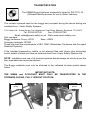
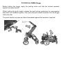
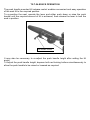
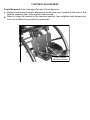
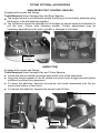
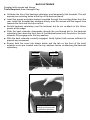
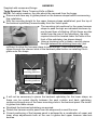
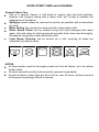
USER MANUAL
Edition 2 2014
CONTENTS
Safety guidelines
Transportation
Unfolding and folding
Tilt—in—space operation
Seat depth and pelvic support adjustment
Footrest adjustment
Fitting optional accessories
Anklesure foot control devices
Abductor
Back extender
Lateral supports
Harness
Ventilator tray/oxygen cylinder carrier
Shopping basket
Upholstery cleaning and care
Product maintenance
Inspection record
Warranty statement
Technical data
SAFETY GUIDELINES
For correct support and user comfort, it is strongly recommended that the initial
installation, any adjustments and final hand-over are carried out by a suitably
qualified person. Hand-over should include passing these instructions to the carer.
A stability test with the intended user may be necessary prior to final issue.
After the buggy has been adjusted to suit the intended user, any settings should
not be affected when folding of the buggy. However, care should be taken not to
impact adjustable components whilst folding or in the folded position.
It is recommended that the user be checked at regular intervals by a suitably
qualified person to ensure that adjustable components are correctly set to suit the
user’s current requirements.
It is recommended that any postural belts or harnesses being used are the first
items to be secured when the user enters the seat and the last items to be
released before exiting.
Regular inspections of the buggy should be made and any defects reported to the
relevant authority for rectification as soon as possible.
The buggy parking brakes should always be applied before attempting to transfer
the occupant or when making any adjustments.
Never leave the buggy parked on a slope with the occupant seated.
Heavy objects should never be suspended from the buggy push handle, as this
could seriously affect the overall stability.
It is recommended that to ensure maximum comfort and correct support, any
adjustments affecting the user’s postural positioning should be carried out by a
suitably qualified person.
NOTE: Any reference to Left or Right in this manual will refer to the Left or Right side
when sitting in the buggy.
TRANSPORTATION
The SIMBA Buggy has been successfully tested to ISO 7176-19
(Wheeled mobility devices for use in Motor Vehicles)
The restraint systems used for the buggy and occupant during the above testing are
available from:- Unwin Safety Systems.
C.N. Unwin Ltd., Unwin House, The Horseshoe, Coat Road, Martock, Somerset, TA12 6EY.
Tel: 01935 827740
Fax: 01935 827760
Email: [email protected] Web: www.unwin-safety.com
Part numbers:Buggy tie-downs: Front—OF03
Rear—OR02
Occupant restraints: OCR02
These kits meet the requirements of ISO 10542 (Wheelchair Tie-downs and Occupant
Restraint Systems).
If the intended transporting vehicle is not already fitted with Unwin type anchorage
tracks, details of these can also be obtained direct from Unwin Safety Systems Ltd.
NOTE: Installation and use of all restraint systems should always be strictly as per the
their manufacturers recommendations.
The Buggy restraints must only be attached to the indicated tie-down points shown
below.
IMPORTANT NOTE:
THE SIMBA and OCCUPANT MUST ONLY BE TRANSPORTED IN THE
FORWARD FACING, FULLY UPRIGHT POSITION.
Front Tie-down
points
Rear Tie-down
points
UNFOLDING the SIMBA Buggy
After carefully removing the buggy from its container and with the parking brakes still
applied, unfold the buggy as shown below in steps 1, 2 and 3 below.
Step 3
Step 2
Step 1
Lock pins are
engaged when
both lock handles
are on RED lines.
NOTE: With the buggy fully unfolded, the
seat locking mechanism is designed to
automatically engage. This can be
confirmed by checking that both lock
handles are on the RED lock lines as shown
and by lightly rocking the push handle
backwards and forwards.
BRAKE PEDAL OPERATION
BRAKE ON
BRAKE OFF
FOLDING the SIMBA Buggy
Before folding the buggy, apply the parking brake and fold the footrest upwards
against its support panel.
Whilst holding the push handle, release the seat locking mechanism by compressing
both seat lock handles together, then push the push handle forwards until the Buggy
folds down flat.
The push handle may also be folded downwards against the backrest if required.
TILT-IN-SPACE OPERATION
The push handle mounted tilt release control enables convenient and easy operation
of the seat tilt to the required position.
To re-position the seat, operate the lever and either push down or raise the push
handle until the required amount of tilt is achieved, then release the lever to lock the
seat in position.
Tilt release control
It may also be necessary to re-adjust the push handle height after setting the tilt
angle.
To adjust the push handle height, depress both red locking buttons simultaneously to
allow the push handle to be raised or lowered as required.
SEAT DEPTH and PELVIC SUPPORT ADJUSTMENT
Tools Required: 5mm Hexagon Key.
Detach and remove the seat cushion.
Raise the footrest and seat panel as an assembly to gain access to the underside
of the seat.
Slacken all four screws just sufficient to be able to reposition the upper seat panel.
Check the pelvic support positions and reposition as required before retightening
all four securing screws sufficient to prevent any movement.
Replace the seat cushion.
Seat panel and pelvic support
securing screws.
Seat panel and pelvic support
securing key washers.
FOOTREST ADJUSTMENT
Tools Required: 4mm Hexagon Key and 10mm Spanner
Slacken both footrest height adjustment screw lock nuts, located at the rear of the
footrest support panel, then slacken both screws.
Raise or lower the footrest to the required position, then retighten both screws and
lock nuts sufficient to prevent any movement.
Footrest height
adjustment screws.
FITTING OPTIONAL ACCESSORIES
ANKLESURE FOOT CONTROL DEVICES
Supplied with screws and fixings.
Tools Required: 4mm Hexagon Key and 8mm Spanner
The buggy footrest is pre-drilled to enable the fitting kit to be directly attached using
the screws, nuts and washers supplied.
The Anklesures should be attached to the bridges as shown below and adjusted to
suit the user. (Velcro style fastening shown). Further adjustments may be
necessary depending on the user’s growth or changes in foot-ware.
Anklesure
bridges
(ABDUCTOR)
Supplied with screws and fixings.
Tools Required: 5mm Hexagon Key and 10mm Spanner.
Locate the two pre-drilled mounting holes at the front of the seat panel.
Using the fixings supplied in the kit, attach the mount to the buggy seat and tighten
sufficient to prevent any movement.
To insert the abductor, depress the pop-pin and push downwards until the pin
locks at the bottom of the mount.
To remove the abductor, depress the pop-pin and lift clear.
Front
Pop-pin
BACK EXTENDER
Supplied with screws and fixings.
Tools Required: 4mm Hexagon Key.
Unfasten the top of the backrest upholstery and temporarily fold forwards. This will
expose two mounting holes at the top of the backrest panel.
Insert the screws and plain washers supplied through the mounting holes from the
rear. Install the threaded key washers loosely onto the screws with the largest face
towards the front and the keys vertical.
Re-fold backrest upholstery over the backrest, but do not re-attach to the Velcro
panels at this stage.
Slide the back extender downwards through the pre-formed slot in the backrest
upholstery then down the front face of the backrest panel until the slots in the back
extender fully engage onto the key washers.
With the back extender correctly engaged, finally tighten both screws sufficient to
prevent any movement.
Ensure both the cover tab shown below and the tab on the front of the back
extender cover are located over the key washers before re-attaching the backrest
upholstery.
Key nuts
Cover Tab
Insert back extender
through pre-formed slot
in backrest upholstery
LATERAL SUPPORTS
Supplied with screws and fixings.
Tools Required: 4mm Hexagon Key.
NOTES:
1/ The lateral supports are supplied complete with screws and fixings.
2/ The lateral supports are handed by virtue of a small recess in the rear of each side
support pad panel. This recess is to assist with retaining the pad and should always
be located at the top.
Separate the upholstery at the rear of the backrest to gain access to the mounting
slots in the backrest panel.
Install the lateral supports one at a time by inserting each support, with the recess
at the top, through the relevant slot in the backrest upholstery from the front. Using
the screws and washers provided insert these from the rear of the backrest panel,
then through into the threaded key washers which should be located in the
mounting slots at the front of the supports.
Position the lateral supports to suit the user’s requirements and finally secure
sufficiently to prevent any movement.
Backrest upholstery
slotted to take lateral
supports
Mounting screws with
large washers
Lateral support
mounting slots
HARNESS
Supplied with screws and fixings.
Tools Required: Sharp Trimming Knife or Blade.
NOTE: For safety reasons, the user should be removed from the buggy.
Remove and save any tri-glides placed on the harness straps before commencing
this installation.
With the mounting height for the upper harness straps established, peel the top of
the backrest upholstery forwards away from the Velcro pads.
The mounting slot positions for the upper harness
straps to pass through are indicated as shown by
pre-formed lines of stitching. Whilst these are also
visible from the rear of the upholstery, the slots
required should be located under the folds at the
front of the upholstery (as shown above).
Using a trimming knife or blade, carefully pierce
through between the stitching lines only, just
sufficient to allow the harness straps to pass through. Then continue routing the
straps through the relevant slots in the backrest panel before re-installing the triglides onto the straps.
Four upper
mounting positions
Two lower
mounting positions
Dynamic harness shown
It will not be necessary to pierce the backrest upholstery for the lower straps, as
these can be routed directly between the seat cushion and back upholstery,
continuing through one of the lower mounting slots in the backrest panel. Re-install
tri-glides onto these straps.
Re-attach the backrest upholstery as required.
Detach the harness centre panel from the straps and re-seat the user.
Correct positioning of the harness panel is achieved by a combination of upper and
lower strap adjustments both at the rear tri-glides and upper harness cam-lock
buckles.
VENTILATOR TRAY / OXYGEN CYLINDER CARRIER
Tools Required: No tools required.
With the parking brakes applied, install the tray/carrier through the rear frame of the
buggy to enable the front supports to hook over the buggy front cross frame and the
rear supports to rest on the rear cross frame. (as shown below)
To prevent the tray from lifting, the rear supports are fitted with turn lock catches
that must be set to the locked positioned (as shown) when in service.
The oxygen cylinder should be inserted from the left side of the buggy with the
valve and connector at the highest point. Webbing retaining straps are supplied to
secure the cylinder in position.
Locked
SHOPPING BASKET
Tools Required: No tools required.
The shopping basket is easily attached to either size of buggy, by routing the webbing
straps around the frame at the six points as shown below and back through their triglides, finally locking in place via their Velcro panels.
UPHOLSTERY CARE and CLEANING
General Fabric Care
Use of a vacuum cleaner or soft brush to remove dust and solid particles,
together with frequent wiping with a damp cloth, will to help to maintain the
appearance of the fabrics.
Spillages should always be removed as quickly as possible with an absorbent
dry cloth.
Minor Soiling can normally be removed with a clean damp cloth.
Water Based Stains can be cleaned using mild liquid detergent with warm
water. Use cold water for stains produced by bodily fluids, then rinse thoroughly,
followed by drying with a clean absorbent cloth.
Light Steam Cleaning can be carried out in situ, ensuring all areas are
completely dry before reuse.
NOTES:
All soap residue must be thoroughly rinsed out from all fabrics, as it can attract
further stains.
All stains caused by bodily fluids should be removed immediately.
As with all fabrics, stains that are left in situ for over 24 hours, will have set and
will become increasingly difficult to remove.
PRODUCT MAINTENANCE
For safety and security, it is recommended that all components are checked for
wear and security at regular intervals.
Inspection frequency should be increased accordingly for heavy users.
Any defects should be reported to the appropriate authority, with any repairs being
carried out using genuine original equipment replacement parts, available direct
from RMS Sales.
(Also refer to Upholstery Maintenance section).
INSPECTION RECORD
DATE
INSPECTED BY
COMMENTS
SIGNED
Should the reader have any concerns regarding the use of the Buggy, please
contact your supplier.
WARRANTY STATEMENT
Every effort is made by RMS Ltd., to ensure that your SIMBA Buggy is
manufactured to the highest standards.
The supply of our quality products is backed by the company’s ISO 9001 –2008
Quality Management System and CE Marking declaration.
The SIMBA Buggy is supplied with a manufacturer’s warranty covering faulty
materials or workmanship. The frame is warranted for a period of 24 months with
all other components, including accessories, warranted for a period of 12 months.
The warranty period commences from the date of dispatch from our factory.
In the unlikely event of a warranty claim being necessary, the failed part must be
returned to your supplier.
The failed part may then be repaired or replaced at the manufacturer’s discretion
or that of their appointed supplier. In the latter case, any displaced parts must be
returned to the manufacturer for inspection.
Any part, component or accessory repaired or replaced during the 12 month
warranty period, will continue to be covered for the balance of the warranty period
only.
As unusually high rates of wear on this device or its ancillary parts may be caused
by the user’s clinical condition, the manufacturer may consider this to be beyond
its control. Therefore, items such as upholstery, wheels and tyres, may only be
considered for repair or replacement under the terms of the product warranty,
where a failure is clearly attributed to a manufacturing or material defect.
With the exception of modifications and / or alterations carried out by the
manufacturer to meet the clinical needs of the user, any attempt to change the
design or modify the construction of the SIMBA Buggy in any way, will invalidate
the product warranty and the manufacturer’s CE marking declaration.
RMS Ltd., reserves the right to change without notice, the design, methods of
manufacture, or any materials used in the construction of the SIMBA Buggy,
where it considers such changes will serve to improve the product quality, or
become necessary to meet any changes in device legislation.
Any unauthorised modification to the Buggy will void the manufacturers product
warranty and the CE marking certification attached to the product.
TECHNICAL DATA
SIZE 1
SIZE 2
MIN
MAX
MIN
MAX
Seat Width with
Pelvic Supports fitted
210
260
260
310
Seat Depth
230
280
280
340
Floor to Seat Height
490
490
520
520
Backrest Height
520
520
570
570
Backrest Height with Headrest
660
660
710
710
Thoracic Support Widths
when fitted
130
190
170
240
Thoracic Support Heights
when fitted
140
360
160
410
Footplate Height
140
290
140
350
Footplate Width
250
250
275
275
Footplate Depth
160
160
180
180
Push Handle Height
900
1170
900
1200
Tilting Angle
10°
46°
10°
48°
Overall Width
620
620
670
670
Overall Depth
720
720
800
800
Overall Height
1050
1050
1070
1070
Overall Height with Back Extender /
Headrest fitted
1090
1090
1150
1150
Standard Buggy Weight (Approx)
16.0Kg
Folded Size
Maximum User Weight
16.0Kg 19.0 Kg
730x620x430
40Kg
40Kg
19.0Kg
770x670x440
40Kg
NOTE: All specifications are in mm unless otherwise stated.
40Kg
GENERAL INFORMATION
Your SIMBA Buggy Serial Number is: ………………......………
Date of Supply: ………………………
Supplied to:
……………………………………………………………….
……………………………………………………………….
Thompson House
Unit 10 Styles Close, Sittingbourne, Kent, ME10 3BF
Tel: 01795 477280 Fax: 01795 229692
E-mail address:[email protected]
www.ineedawheelchair.co.uk