1
20PU20-00 E1 – 2014-06-30
User Manual
PU20 – Wide-Range PSU
for 19“ Railway Systems,
24 to 110 VDC, 120 W
PU20 – Wide-Range PSU for 19" Railway Systems, 24 to 110 VDC, 120 W
PU20 – Wide-Range PSU for 19" Railway Systems,
24 to 110 VDC, 120 W
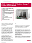
The PU20 is a plug-in power supply unit for 19" systems (like VMEbus and
CompactPCI® Serial). It is especially designed for computer systems in public
transport vehicles and for harsh environments, like railway applications, making it
suitable for both onboard and wayside use.
The PU20 has a nominal input power range of 24 V to 110 V with a max. input
voltage range of 14.6 to 156 VDC (according to EN 50155 and S-9401). It also has
an automatic input voltage range detection for 24, 72, 110 VDC, to define the undervoltage level. Additionally, the PU20 has a configurable voltage range for 36, 48,
74, 96 VDC, which is controlled by a rotary switch.
The standard output voltage is 5 V with a dynamic load sharing of between 12 and
5 V with 120 W. The output power at 3.3 V is 35 W, which is shared with the 5 V
load. Switch-on behavior is independent of the load.
The PU20 also has a standby voltage of 5 V with 5W to supply the independent
shelf controller, and to support wake-on-LAN functionality.
The PSU provides three ports, on the secondary side, for switching the output
voltages. They also indicate the event of an input power failure, output voltage
failure or a fail-over temperature.
The PSU is coated conformally, and all components are secured against vibration.
When more power supplies run in parallel, the performance loss is shared evenly
and, in case of a fault in one of the power supplies, the output power is removed
completely so as to avoid any negative effects. The double power monitoring
ensures that the output voltage is within the valid range. In case of error, the voltage
is powered-down as prepared by the SIL applications. The thermal stress is
extremely low due to integrated heat sinks, and diversion of dissipated heat over the
mounting surface.
The PU20 is fully compliant with EN 50155, meeting all shock, vibration, EMC and
isolation requirements. Operating under temperatures ranging from -40 to 70°C
with increments to 85°C for 10 minutes (class TX), with a hold up time of 10 ms, as
is in accordance with EN 50155 Class 2.
MEN Mikro Elektronik GmbH
20PU20-00 E1 – 2014-06-30
2
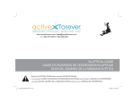
Diagram
Diagram
R
Rear I/O connector
EMC Surge
Protection
PE
Rotary
Switch
Input Voltage Range Definition
Status
LED
Power OK
Failure Switch Off
12 VDC OUT
Class S2 (10ms)
Double Isolated
5 VDC OUT
3.3 VDC OUT
Voltage Monitoring unit
Standby power 5 VDC
H15
Current sharing control
Automatic Voltage Range Detection
5 VDC SENSE
OverTemp/Output voltage fail
PS_ON#
Input power good
R
MEN Mikro Elektronik GmbH
20PU20-00 E1 – 2014-06-30
3
Technical Data
Technical Data
Input Characteristics
• Nominal voltage input: 24 V, 36 V, 48 V, 72 V, 96 V, 110 V
(according to EN50155)
- Max. input power range of 14.6 to 156 VDC
- Automatic input voltage range detection for 24, 72, 110 VDC
- Configurable voltage range for 36, 48, 74, 96 VDC
- Power-on/-off threshold
• Input voltage range
- Nominal input voltage of 74 VDC provided
(according to S-9401)
- Voltage range for 74 VDC is 20 to 130 VDC
• Power Variations
- No functional disturbance with input voltage variations of:
0.6 x Un < 1.4 x Un for 0.1 s
- No functional disturbance with input voltage variations of:
1.25 x Un < 1.4 Un for 1 s
• Inrush current limiting
Output Characteristics
•
•
•
•
•
Output voltages: 12 VDC, 5 VDC and 3.3 VDC
Standby output voltage: 5 VDC with a 5 W load
Accuracy: Max. ±1% of the nominal value
Holdup time: 10 ms according to Class S2
Dynamic load distribution
- 120 W for complete temperature range without forced airflow
- Load sharing between 12 VDC output and 5 VDC output, including 3.3 VDC
Connection
• Type H15, DIN 41612 plug connector
Control and Status Indicator
• Three ports on secondary side
- Switches output voltages
- Indicates input power failure, output voltage failure or fail-over temperature
Parallel connection
• Up to six power supply units can be used in parallel
- Extends availability (backup protection against faults)
- Extends power
- Increases performance
- Ensures redundancy
MEN Mikro Elektronik GmbH
20PU20-00 E1 – 2014-06-30
4
Technical Data
Miscellaneous
•
•
•
•
•
•
Overload and short circuit protection
Standby voltage at power down, always available
Reverse polarity protection for input voltage and short circuit
Output voltage and temperature supervision
Overtemperature and overvoltage shutdown
Status LED on front panel
Electrical Specifications
• Isolation (according to EN 50155)
- Input/output: 3100 VAC
- Input/shield: 3100 VAC
- Output/shield: 1000 VAC
Mechanical Specifications
• Dimensions: 3U, 5HP
• Integrated heat sink
• Weight: tbd
Environmental Specifications
• Temperature range (operation): -40 to +70°C (85°C/10 mins), no derating
• Temperature range (storage): -50 to +85°C
• Temperature: 70°C, with up to 85°C for 10 minutes
according to class Tx (EN 50155)
• EMC Emission:
- EN 55022: CISPR 22 – Class B
- FCC 15.109 and S-9401
• EMC Immunity: EN 55024 – Class A
• Airflow: convection cooling
• Cooling test according to EN 60068-2-1
• Dry heat test according to EN 60068-2-2
• Shock: 50 m/s², 30 ms (EN 61373)
• Vibration (function): 2.02 m/s², 5 Hz to 200 Hz (EN 61373)
• Vibration (lifetime): 11.44 m/s², 5 Hz to 200 Hz (EN 61373)
MTBF
• min. 600 000h @ 40°C according to IEC/TR 62380 (RDF 2000)
Safety
• Flammability
- PCB manufactured with a flammability rating of 94V-0 by UL recognized
manufacturers
• Electrical Safety
- EN 60950-1
- Insulation measurement test according to EN 50155 (12.2.9.1)
- Voltage withstand test according to EN 50155 (12.2.9.2)
MEN Mikro Elektronik GmbH
20PU20-00 E1 – 2014-06-30
5
Configuration Options
EMC Conformity
•
•
•
•
•
•
EN 55011 (radio disturbance)
IEC 61000-4-2 (ESD)
IEC 61000-4-3 (electromagnetic field immunity)
IEC 61000-4-4 (burst)
IEC 61000-4-5 (surge)
IEC 61000-4-6 (conducted disturbances)
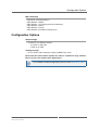
Configuration Options
Output voltage
• Available in two different models:
- 14.4 VDC to 156 VDC
- 9 VDC to 36 VDC
Cooling Concept
• Also available with conduction cooling in MEN CCA frame
Please note that some of these options may only be available for large volumes.
Please ask our sales staff for more information.
For available standard configurations please see the online data sheet.
MEN Mikro Elektronik GmbH
20PU20-00 E1 – 2014-06-30
6
Product Safety
Product Safety
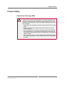
Electrostatic Discharge (ESD)
!
MEN Mikro Elektronik GmbH
20PU20-00 E1 – 2014-06-30
Computer boards and components contain electrostatic sensitive
devices. Electrostatic discharge (ESD) can damage components. To
protect the board and other components against damage from static
electricity, you should follow some precautions whenever you work on
your computer.
• Power down and unplug your computer system when working on the
inside.
• Hold components by the edges and try not to touch the IC chips,
leads, or circuitry.
• Use a grounded wrist strap before handling computer components.
• Place components on a grounded antistatic pad or on the bag that
came with the component whenever the components are separated
from the system.
• Only store the board in its original ESD-protected packaging. Retain
the original packaging in case you need to return the board to MEN
for repair.
7
About this Document
About this Document
This user manual is intended only for system developers and integrators, it is not
intended for end users.
It describes the hardware functions of the board, connection of peripheral devices
and integration into a system. It also provides additional information for special
applications and configurations of the board.
The manual does not include detailed information on individual components (data
sheets etc.). A list of literature is given in the appendix.
History
Issue
Date
E1
First issue
2014-06-05
E2
Updated photos and front panel - cosmetics only
2014-06-30
MEN Mikro Elektronik GmbH
20PU20-00 E1 – 2014-06-30
Comments
8
About this Document
Conventions
Indicates important information or warnings concerning the use of
voltages that could lead to a hazardous situation which could result in
personal injury, or damage or destruction of the component.
!
Indicates important information or warnings concerning proper
functionality of the product described in this document.
The globe icon indicates a hyperlink that links directly to the Internet,
where the latest updated information is available.
When no globe icon is present, the hyperlink links to specific elements
and information within this document.
italics
Folder, file and function names are printed in italics.
bold
Bold type is used for emphasis.
mono
A monospaced font type is used for hexadecimal numbers, listings, C
function descriptions or wherever appropriate. Hexadecimal numbers
are preceded by "0x".
comment
Comments embedded into coding examples are shown in green text.
IRQ#
/IRQ
Signal names followed by a hashtag "#" or preceded by a forward
slash "/" indicate that this signal is either active low or that it becomes
active at a falling edge.
in/out
Signal directions in signal mnemonics tables generally refer to the
corresponding board or component, "in" meaning "to the board or
component", "out" meaning "from it the board or component".
Blue vertical lines in the outer margin indicate sections where changes
have been made to this version of the document.
MEN Mikro Elektronik GmbH
20PU20-00 E1 – 2014-06-30
9
About this Document
Legal Information
Changes
MEN Mikro Elektronik GmbH ("MEN") reserves the right to make changes without further notice to any products
herein.
Warranty, Guarantee, Liability
MEN makes no warranty, representation or guarantee of any kind regarding the suitability of its products for any
particular purpose, nor does MEN assume any liability arising out of the application or use of any product or
circuit, and specifically disclaims any and all liability, including, without limitation, consequential or incidental
damages. TO THE EXTENT APPLICABLE, SPECIFICALLY EXCLUDED ARE ANY IMPLIED
WARRANTIES ARISING BY OPERATION OF LAW, CUSTOM OR USAGE, INCLUDING WITHOUT
LIMITATION, THE IMPLIED WARRANTIES OF MERCHANTABILITY AND FITNESS FOR A
PARTICULAR PURPOSE OR USE. In no event shall MEN be liable for more than the contract price for the
products in question. If buyer does not notify MEN in writing within the foregoing warranty period, MEN shall
have no liability or obligation to buyer hereunder.
The publication is provided on the terms and understanding that:
1. MEN is not responsible for the results of any actions taken on the basis of information in the publication, nor
for any error in or omission from the publication; and
2. MEN is not engaged in rendering technical or other advice or services.
MEN expressly disclaims all and any liability and responsibility to any person, whether a reader of the publication
or not, in respect of anything, and of the consequences of anything, done or omitted to be done by any such person
in reliance, whether wholly or partially, on the whole or any part of the contents of the publication.
Conditions for Use, Field of Application
The correct function of MEN products in mission-critical and life-critical applications is limited to the
environmental specification given for each product in the technical user manual. The correct function of MEN
products under extended environmental conditions is limited to the individual requirement specification and
subsequent validation documents for each product for the applicable use case and has to be agreed upon in writing
by MEN and the customer. Should the customer purchase or use MEN products for any unintended or
unauthorized application, the customer shall indemnify and hold MEN and its officers, employees, subsidiaries,
affiliates, and distributors harmless against all claims, costs, damages, and expenses, and reasonable attorney fees
arising out of, directly or indirectly, any claim or personal injury or death associated with such unintended or
unauthorized use, even if such claim alleges that MEN was negligent regarding the design or manufacture of the
part. In no case is MEN liable for the correct function of the technical installation where MEN products are a part
of.
Trademarks
All products or services mentioned in this publication are identified by the trademarks, service marks, or product
names as designated by the companies which market those products. The trademarks and registered trademarks
are held by the companies producing them. Inquiries concerning such trademarks should be made directly to those
companies.
Conformity
MEN products are no ready-made products for end users. They are tested according to the standards given in the
Technical Data and thus enable you to achieve certification of the product according to the standards applicable in
your field of application.
MEN Mikro Elektronik GmbH
20PU20-00 E1 – 2014-06-30
10
About this Document
RoHS
Since July 1, 2006 all MEN standard products comply with RoHS legislation.
Since January 2005 the SMD and manual soldering processes at MEN have already been completely lead-free.
Between June 2004 and June 30, 2006 MEN’s selected component suppliers have changed delivery to RoHScompliant parts. During this period any change and status was traceable through the MEN ERP system and the
boards gradually became RoHS-compliant.
WEEE Application
The WEEE directive does not apply to fixed industrial plants and tools. The compliance is the responsibility of the
company which puts the product on the market, as defined in the directive; components and sub-assemblies are
not subject to product compliance.
In other words: Since MEN does not deliver ready-made products to end users, the WEEE directive is not
applicable for MEN. Users are nevertheless recommended to properly recycle all electronic boards which have
passed their life cycle.
Nevertheless, MEN is registered as a manufacturer in Germany. The registration number can be provided on
request.
Copyright © 2014 MEN Mikro Elektronik GmbH. All rights reserved.
Germany
MEN Mikro Elektronik GmbH
Neuwieder Straße 3-7
90411 Nuremberg
Phone +49-911-99 33 5-0
Fax +49-911-99 33 5-901
E-mail [email protected]
www.men.de
MEN Mikro Elektronik GmbH
20PU20-00 E1 – 2014-06-30
France
MEN Mikro Elektronik SAS
18, rue René Cassin
ZA de la Châtelaine
74240 Gaillard
Phone +33 (0) 450-955-312
Fax +33 (0) 450-955-211
E-mail [email protected]
www.men-france.fr
USA
MEN Micro Inc.
860 Penllyn Blue Bell Pike
Blue Bell, PA 19422
Phone (215) 542-9575
Fax (215) 542-9577
E-mail [email protected]
www.menmicro.com
11
Contents
Contents
1 Getting Started . . . . . . . . . . . . . . . . . . . . . . . . . . . . . . . . . . . . . . . . . . . . . . . . 15
1.1 Map of the Board. . . . . . . . . . . . . . . . . . . . . . . . . . . . . . . . . . . . . . . . . 15
1.2 Integrating the Board into a System . . . . . . . . . . . . . . . . . . . . . . . . . . 15
2 Connecting the PSU . . . . . . . . . . . . . . . . . . . . . . . . . . . . . . . . . . . . . . . . . . . .
2.1 Parallel . . . . . . . . . . . . . . . . . . . . . . . . . . . . . . . . . . . . . . . . . . . . . . . . .
2.2 Redundant Mode . . . . . . . . . . . . . . . . . . . . . . . . . . . . . . . . . . . . . . . . .
2.3 Using an Integrated Shelf Controller. . . . . . . . . . . . . . . . . . . . . . . . . .
16
17
17
17
3 Functional Description . . . . . . . . . . . . . . . . . . . . . . . . . . . . . . . . . . . . . . . . . .
3.1 Voltage Range Compliance . . . . . . . . . . . . . . . . . . . . . . . . . . . . . . . . .
3.1.1
Automatic Voltage Range Detection . . . . . . . . . . . . . . . . . . .
3.1.2
Manual Voltage Range Configuration. . . . . . . . . . . . . . . . . .
3.1.3
Voltage Variations or Interruptions . . . . . . . . . . . . . . . . . . . .
3.1.4
Inrush Current and Reverse Polarity Protection . . . . . . . . . .
3.2 Voltage and Current Management . . . . . . . . . . . . . . . . . . . . . . . . . . . .
3.2.1
Output Voltages. . . . . . . . . . . . . . . . . . . . . . . . . . . . . . . . . . .
3.2.2
Standby Voltage . . . . . . . . . . . . . . . . . . . . . . . . . . . . . . . . . .
3.2.3
Load Sharing . . . . . . . . . . . . . . . . . . . . . . . . . . . . . . . . . . . . .
3.3 Status Signals and LED . . . . . . . . . . . . . . . . . . . . . . . . . . . . . . . . . . . .
3.4 Isolation . . . . . . . . . . . . . . . . . . . . . . . . . . . . . . . . . . . . . . . . . . . . . . . .
3.4.1
Isolation Groups . . . . . . . . . . . . . . . . . . . . . . . . . . . . . . . . . .
3.4.2
Isolation Voltages . . . . . . . . . . . . . . . . . . . . . . . . . . . . . . . . .
18
18
18
18
18
19
19
19
19
20
21
22
22
22
4 General Information . . . . . . . . . . . . . . . . . . . . . . . . . . . . . . . . . . . . . . . . . . . . 23
5 Appendix . . . . . . . . . . . . . . . . . . . . . . . . . . . . . . . . . . . . . . . . . . . . . . . . . . . . . 24
5.1 Literature and Web Resources . . . . . . . . . . . . . . . . . . . . . . . . . . . . . . . 24
5.2 Finding out the Board’s Article Number, Revision
and Serial Number . . . . . . . . . . . . . . . . . . . . . . . . . . . . . . . . . . . . . . . . 24
MEN Mikro Elektronik GmbH
20PU20-00 E1 – 2014-06-30
12
Figures
Figure 1.
Figure 2.
Figure 3.
Figure 4.
MEN Mikro Elektronik GmbH
20PU20-00 E1 – 2014-06-30
Map of the board – front panel and top view . . . . . . . . . . . . . . . . . . . .
PU20 Status LEDs . . . . . . . . . . . . . . . . . . . . . . . . . . . . . . . . . . . . . . . .
Safety application . . . . . . . . . . . . . . . . . . . . . . . . . . . . . . . . . . . . . . . . .
Labels with the article number, revision
and serial number of the board . . . . . . . . . . . . . . . . . . . . . . . . . . . . . . .
15
21
23
24
13
Tables
Table 1.
Table 2.
Table 3.
Table 4.
Table 5.
Table 6.
Table 7.
Table 8.
MEN Mikro Elektronik GmbH
20PU20-00 E1 – 2014-06-30
Pin assignment of rear H15 PSU connector . . . . . . . . . . . . . . . . . . . . .
Signal mnemonics of PSU interfaces . . . . . . . . . . . . . . . . . . . . . . . . . .
Automatic and configurable voltage range overview. . . . . . . . . . . . . .
Capacitive Load . . . . . . . . . . . . . . . . . . . . . . . . . . . . . . . . . . . . . . . . . .
Status signals on the front panel . . . . . . . . . . . . . . . . . . . . . . . . . . . . . .
Yellow status LED on the front panel . . . . . . . . . . . . . . . . . . . . . . . . .
Isolation groups . . . . . . . . . . . . . . . . . . . . . . . . . . . . . . . . . . . . . . . . . .
Isolation voltages . . . . . . . . . . . . . . . . . . . . . . . . . . . . . . . . . . . . . . . . .
16
16
18
20
21
21
22
22
14
Getting Started
1
Getting Started
This chapter contains a general overview of the board, and some information
regarding the initial installation in a system.
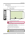
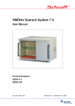
1.1
Map of the Board
Figure 1. Map of the board – front panel and top view
Mounting screw
H15 Connector Rear
PSU DC/DC 120W
OUTPUT OK
OUTPUT FAIL
INPUT FAIL
Status LEDs
1
2
3
8
7
4
0
5
9
6
Handle
Mounting screw
1.2
Rotary Switch
Fuse
Integrating the Board into a System
!
This chapter contains important information regarding initial installation
of the PU20.
The PU20 is hot pluggable, it is therefore not necessary to shut down the host
system during installation, there will also be no significant interruptions to the
system while installing or replacing this unit.
Only operate the PU20 in a suitable housing, i.e. in such a way that no parts of
the PU20 except the front panel can be touched.
Make sure that enough convection airflow is provided.
Do not remove any covers or other mechanical parts.
The guiderails should be made of synthetic material and not touch any components.
To reduce the risk of electrical shock, do not disassemble or attempt to
repair the power supply unit. Replace it only with the specified units from
the MEN PSU family.
MEN Mikro Elektronik GmbH
20PU20-00 E1 – 2014-06-30
15
Connecting the PSU
2
Connecting the PSU
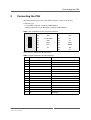
The PU20 must be connected via the H15 connector at the rear of the unit.
Connector type:
• 15-pin H15 receptacle according to IEC 60603-2
• Mating connector: 15-pin H15 plug according to IEC 60603-2
Table 1. Pin assignment of rear H15 PSU connector
6
30
4
6
Vo1+
4
Vo1+
10
Vo2-
8
Vo1-
14
5 V Standby
12
S+
18
Vo2+
16
T1
22
FAL#
20
Vo3+
26
PUL, i
24
DEG#
30
Vi+
28
PE
32
Vi-
32
Note: Pin 32 is longer than the other pins.
Table 2. Signal mnemonics of PSU interfaces
Pin
Function
4
Vo1+
Output 1 pos (+5VDC)
6
Vo1+
Output 1 pos (+5VDC)
8
Vo1-
Output 1 neg. (GND)
10
Vo2-
Output 2 neg. (GND)
12
S+
Sense + (sense + 5VDC)
14
5 V Standby
5V Standby
16
T1
5V current share
18
Vo2+
Output 2 pos (+12VDC)
20
Vo3+
Output 3 pos (+3,3VDC)
22
FAL#
Input_Voltage_Good
24
DEG#
OverTemp
26
PUL, i
PS_ON#
28
PE
Prot. Earth PE
30
Vi+
Input pos.
32
Vi-
Input neg.
MEN Mikro Elektronik GmbH
20PU20-00 E1 – 2014-06-30
Signal
16
Connecting the PSU
2.1
Parallel Mode
The PU20 can be used in parallel with up to six additional units from the MEN PSU
family, which are easily scalable so that the required output power can be achieved
This not only increases the output power, but also allows balanced dissipation loss
for all units, which leads to a better MTBF.
2.2
Redundant Mode
The PU20 can also be used in a redundant configuration. Redundancy maximizes
the availability of a system in critical applications. In addition, reliability is
enhanced as the modules are operating below the full output current rating, thereby
reducing power dissipation and temperature rise. An output voltage fault, or the
complete failure of one power supply will not affect the remaining PSUs.
The PU20 can be used in parallel with the PU21, which is also available
from MEN
2.3
Using an Integrated Shelf Controller
When using multiple PSUs, an independent shelf controller can be installed
between two units. The shelf controller allows communication between units, and
controls and supervises the speed of up to three cooling fans.
The shelf controller also provides a front panel display which displays the PSU
supply status and hosts the power button.
For more information on the shelf controller, please refer to the host
system manual. An overview of complete systems and documentation is
available on the MEN website.
MEN Mikro Elektronik GmbH
20PU20-00 E1 – 2014-06-30
17
Functional Description
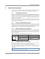
3
Functional Description
The functions described in the following chapter depend on the firmware. This user
manual describes the functions realized in the current MEN standard firmware.
3.1
Voltage Range Compliance
The PU20 is fully compliant with the voltage requirements for input voltages as
specified by the EN50155 railway standards and provides the nominal input
voltages 24, 26, 48, 72, 96 and 110 VDC. In addition, the PU20 also provides the
possibility to extend the power input with an assembly option which allows an input
range from 9 up to 36 VDC.
The PU20 is also compliant with the S-9401 Standard for Railroad Electronics
Environmental Requirements, and provides a nominal input voltage of 74 VDC with
a voltage range of 20 to 130 VDC.
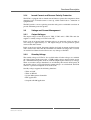
3.1.1
Automatic Voltage Range Detection
The PU20 has an automatic voltage range detection for voltages 24, 72 and 110
VDC. The automatic voltage detection feature helps ensure automatic switch off
when necessary, to avoid overloads and to protect the batteries, if used, against
discharging when there is a drop in voltage in an electrical power supply.
3.1.2
Manual Voltage Range Configuration
The automatic voltage range detection only detects voltages 24, 72 and 110 VDC. In
order to compensate for the other voltages and cover the entire range, the PU20 also
features a rotary switch which allows the voltages to also be manually configured to
36, 48, 74 or 96 VDC.
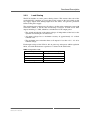
Table 3. Automatic and configurable voltage range overview
Rotary Switch
48
36
74
96
3.1.3
Configurable
Automatic Detection
36 VDC
24 VDC
48 VDC
72 VDC
74 VDC
110 VDC
96 VDC
Voltage Variations or Interruptions
Input voltage variations of 0.6 x Un up to 1.4 Un for less than 0.1s, and 1.25 x Un up
to 1.4 x Un for less than 1s, will not cause any functional disturbance.
The PU20 is compliant with class S2 of EN50155 power interruption and input
short circuit regulations. Interruptions of up to 10 ms will not lead to any
disturbances.
The PU20 is unconditionally stable under all load conditions, including capacitive
load, see Table 4, Capacitive Load on page 20
MEN Mikro Elektronik GmbH
20PU20-00 E1 – 2014-06-30
18
Functional Description
3.1.4
Inrush Current and Reverse Polarity Protection
The PU20 is equipped with an inrush current limiter to protect the components from
damaging levels of inrush current at start up, which could lead to a reduction of
equipment life.
The PSU provides a reverse polarity protection using active switchable transistors to
provide minimum power dissipation.
3.2
Voltage and Current Management
3.2.1
Output Voltages
The output voltages of the PU20 are 12 VDC, 5 VDC and 3.3 VDC. The unit also
supplies a standby voltage of 5 VDC with 5 W.
In the event of an internal fault, all output voltages are protected against an under or
over-voltage of approximately 5%. All output voltages are also protected against
overload and short circuits.
In the event of an overload, the output switches itself off. An output overload occurs
with a load of 20% more than the maximum load which lasts longer than 1 second.
An overload and short circuit will not cause any damage to the PSU.
3.2.2
Standby Voltage
The standby voltage of 5 VDC is also available when all other voltages are switched
off. After removal of the power, the +5 VSB standby voltage output remains steady
for a minimum hold-up time of 16 ms, until the output begins to decrease in voltage.
There are no other voltage disturbances at or following the removal of DC power. If
the standby voltage is not used when the output voltages are switched off, the PU20
will have a power consumption of less than 0.5 W.
Standby voltage supports the following functions:
•
•
•
•
•
Wake on LAN
Wake on WLAN
System Management Controller
RTC application
Suspend to RAM application
MEN Mikro Elektronik GmbH
20PU20-00 E1 – 2014-06-30
19
Functional Description
3.2.3
Load Sharing
The PU20 includes an active power sharing feature. This ensures that each of the
paralleled PSUs contribute an equal share of the current to the load, which avoids
any supply output from drifting higher than the others, and prevents premature
failure of the power supply.
The maximum power output over all voltages, for the entire temperature range with
convection airflow, is 120 W. The load sharing is between 12 VDC and 5 VDC
output, including 3.3 VDC, which has a minimum of 35 W output power.
• The switch on behavior of the output voltages is independent of the load, so the
dynamic load sharing has no effect on it.
• All output voltages have a maximum accuracy of approximately 1% of their
nominal value.
• The maximum over and under shoot at all outputs is less than +4% / -2% of its
nominal voltage.
Each output voltage of the PU20 is able to power up and operate within regulation
limits, and with simultaneous capacitances as shown in the table below:
Table 4. Capacitive Load
Output
12 VDC
10 000
5 VDC
10 000
3.3 VDC
10 000
5 VDC (standby)
5 000
MEN Mikro Elektronik GmbH
20PU20-00 E1 – 2014-06-30
Capacitive load (μF)
20
Functional Description
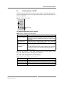
3.3
Status Signals and LED
The PU20 provides three ports on the secondary side for switching output voltages,
as well as indicating the event of an input power failure, output voltage failure or a
fail-over temperature.
Figure 2. PU20 Status LEDs
OUTPUT OK
OUTPUT FAIL
INPUT FAIL
Status LED
The signal assignments are as follows:
Table 5. Status signals on the front panel
Signal
Function
Input Power Good
Indicates when input voltage is within the valid range,
Indicates when input voltage falls below the under-voltage
threshold
Over temperature
output
Indicates when the temperature is within 15K of a thermal
power shut down or output voltage fail
PS_ON#
(Active low and TTL
compatible)
Allows CPU to remotely control the power supply for soft
on/off and wake-on-lan,
TTL low: the three main DC output voltages are turned on.
TTL high or open-circuit: the DC output voltages do not
deliver current
The PU20 also provides a yellow LED which displays the correct output voltage
range. The LED is located on the front panel of the unit.
The LED status assignments are as follows:
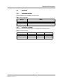
Table 6. Yellow status LED on the front panel
Yellow LED
LED on
Output voltages are in valid range
LED blinking
Output voltages are not in valid range
LED off
Input voltage range is not valid
MEN Mikro Elektronik GmbH
20PU20-00 E1 – 2014-06-30
Function
21
Functional Description
3.4
Isolation
3.4.1
Isolation Groups
The PU20 provides the following isolated groups:
Table 7. Isolation groups
Group
Name
1
Primary power (voltage input)
2
Secondary power (all outputs and status ports)
3
Shield
3.4.2
Isolation Voltages
The PU20 can withstand high voltages according to the following table:
Table 8. Isolation voltages
Group
2
3
1
-
-
-
2
3100 VAC
-
-
3
3100 VAC
1000 VAC
-
MEN Mikro Elektronik GmbH
20PU20-00 E1 – 2014-06-30
1
22
General Information
4
General Information
The PU20 features a catastrophic failure protection function and voltage accuracy is
consistently double checked. In the event of one unit failing, another unit will
continue to check the accuracy and switch all voltages off if necessary, before any
thermal damage is caused.
Figure 3. Safety application
DC/DC converter
Input Voltage
Output Voltages
off
off
+
‐
reference
+
‐
reference
Repeated switching on and off of the DC input voltage with a maximum load will
not cause any damage to the power supply, nor will it cause the input fuse to blow.
The PU20 is compliant to the CPCI 3U standard and has a width of not more than
6HP.
A CCA version of the PU20 is also available, and is 3U and 5HP, compliant to the
CPCI-S.0 specifications.
It is also possible to integrate CPCI-S 3U boards on both sides of the power supply
unit without any additional space necessary between boards.
The PU20 is available in two models:
• Voltage range from 14.4 VDC to 156 VDC
• Voltage range from 9 VDC to 36 VDC
MEN Mikro Elektronik GmbH
20PU20-00 E1 – 2014-06-30
23
Appendix
5
Appendix
5.1
Literature and Web Resources
PU20 data sheet with up-to-date information and documentation:
www.men.de/products/17pu20-.html
5.2
Finding out the Board’s Article Number, Revision and
Serial Number
MEN user documentation may describe several different models and/or hardware
revisions of the PU20. You can find information on the article number, the board
revision and the serial number on two labels attached to the board.
• Article number: Gives the board’s family and model. This is also MEN’s ordering number. To be complete it must have 9 characters.
• Revision number: Gives the hardware revision of the board.
• Serial number: Unique identification assigned during production.
If you need support, you should communicate these numbers to MEN.
Figure 4. Labels with the article number, revision and serial number of the board
Complete article number
17PU20-00
00.00.00
Revision number
Serial number
MEN Mikro Elektronik GmbH
20PU20-00 E1 – 2014-06-30
24