1
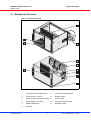
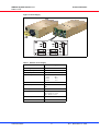
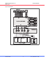
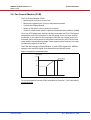
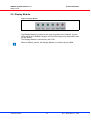
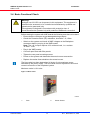
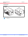
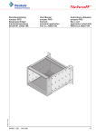
VME64x Subrack System 7 U
User Manual
Product Numbers:
20836-717
20836-720
Doc-No: 63972-146
Revision: R1.1, November 14, 2007
Rev.
Date updated
Change
R1.0
August 23, 2006
Initial release
R1.1
November 14, 2007 Minor corrections
Impressum:
Schroff GmbH
D-75334 Straubenhardt, Germany
The details in this manual have been carefully compiled and
checked - supported by certified Quality Management System
to EN ISO 9001/2000
The company cannot accept any liability for errors or misprints.
The company reserves the right to amendments of technical
specifications due to further development and improvement of
products.
Copyright
© 2006
All rights and technical modifications reserved.
VME64x System Subrack 7 U
20836-717/-720
Table of Contents
1
2
3
4
Safety ................................................................................................................. 1
1.1
Indended Application ........................................................................................... 1
1.2
Safety Instructions ............................................................................................... 2
1.3
Safety Symbols used in this document................................................................ 2
1.4
General Safety Precautions................................................................................. 2
1.5
References and Architecture Specifications ........................................................ 3
Product Definition............................................................................................. 4
2.1
Mechanical Overview........................................................................................... 5
2.2
Subrack................................................................................................................ 6
2.3
VME Backplane ................................................................................................... 6
2.4
Power Supply....................................................................................................... 7
2.5
2.4.1
Grounding .............................................................................................. 7
Thermals............................................................................................................ 10
2.6
Fan Control Module (FCM) ................................................................................ 11
2.7
Chassis Monitoring Module (CMM) -optional- ................................................... 12
2.8
Display Module .................................................................................................. 13
Installation....................................................................................................... 14
3.1
Unpacking.......................................................................................................... 14
3.2
3.1.1
Ensuring Proper Airflow ....................................................................... 14
Rack-Mounting................................................................................................... 15
3.3
Assembly of additional Backplanes ................................................................... 16
3.4
Basic Functional Check ..................................................................................... 17
Service ............................................................................................................. 18
4.1
Technical support and Return for Service Assistance ....................................... 18
4.2
Declaration of Conformity .................................................................................. 18
4.3
Scope of delivery ............................................................................................... 19
4.4
Accessories ....................................................................................................... 19
4.5
Spare Parts........................................................................................................ 19
5
Technical Data ................................................................................................ 20
6
Dimensions ..................................................................................................... 21
www.schroff.biz
I
R1.1, November 14, 2007
VME64x System Subrack 7 U
20836-717/-720
www.schroff.biz
II
R1.1, November 14, 2007
VME64x System Subrack 7 U
Safety
20836-717/-720
1 Safety
1.1 Intended Application
The VME system subrack, described in this manual, is intended as a platform
for a microcomputer system based on the VME bus system (VME (VITA 1-1994)
and VME64x (VITA 1.1-1997)).
The VME64x system subracks are designed for protection class IP 20 and can
be used only in the resp. environments.
For higher protection requirements, a.e. IP 54/55 you must install the system
subrack in a protective case.
VME64x system subracks are not end-products, so there is no valid approval for
this unit. In order to enable stand-alone functionality, additional elements are
required. An operational system is achieved only by way of appropriate VME or
VME64x boards.
The completion and final testing of the units have been carried out, or at least
supervised, by qualified technicians. These instructions are directed exclusively
to these qualified technicians i.e.engineers, trained and qualified electricians
etc.
Make sure that:
• the assembled unit complies with the safety regulations currently applicable
in the country it is going to be used.
• the overall unit complies with all other regulations and specifications at the
place and country of use, e.g. interference limits, approval by the telecommunications authorities.
www.schroff.biz
1
R1.1, November 14, 2007
VME64x System Subrack 7 U
Safety
20836-717/-720
1.2 Safety Instructions
The intended audience of this User’s Manual is system integrators and
hardware/software engineers.
1.3 Safety Symbols used in this document
Hazardous voltage!
This is the electrical hazard symbol. It indicates that there are dangerous
voltages inside the Shelf.
Caution!
This is the user caution symbol. It indicates a condition where damage of the
equipment or injury of the service personnel could occur. To reduce the risk of
damage or injury, follow all steps or procedures as instructed.
Danger of electrostatic discharge!
The Shelf contains static sensitive devices. To prevent static damage you must
wear an ESD wrist strap.
1.4 General Safety Precautions
Warning!
Voltages over 60 VDC can be present in this equipment. This equipment is
intended to be accessed, to be installed and maintained by qualified and
trained service personnel only.
This equipment is designed in accordance with protection class 1!
It must therefore be operated only with protective GND/earth connection!
• Service personnel must know the necessary electrical safety, wiring and
connection practices for installing this equipment in a telecommunication
environment.
• Install this equipment only in compliance with local and national electrical
codes.
www.schroff.biz
2
R1.1, November 14, 2007
VME64x System Subrack 7 U
Safety
20836-717/-720
1.5 References and Architecture Specifications
• User Manual VME64x Backplanes
Order no.: 73972-103
• Short Form User Manual VME64x Backplanes
Order no.: 73972-128
• User Manual Fan Control Module (FCM)
Order no.: 73972-083
For more information see the catalogue „Electronic Packaging“ and at
www.schroff.biz
www.schroff.biz
3
R1.1, November 14, 2007
VME64x System Subrack 7 U
Product Definition
20836-717/-720
2 Product Definition
The Schroff VME subrack system consists of:
• A shielded 19“ subrack with front assembly area for
6 U front boards according to VME64x Standard (VITA 1.1-1997)
• A VME64x (VITA 1.1-1997) Backplane
• An open frame power supply with wide range input
• Speed controlled fans for cooling the boards
• Fan Control Module (FCM) for fan monitoring/controlling
• Display module
• Mains/line switch
• Rear assembly area for three 6 U, 4 HP Rear Transition Modules
The fans and the power supply are assembled on the bottom-hinged rear panel.
System differences:
The subracks 20836-717/-720 are identical in their construction. The only
difference is the depth (355 mm/475 mm).
Variations
The Schroff assembly service can customize your subrack system with:
• Different Backplane configurations
• Drive mounting cassettes
• Special power supplies
• A Chassis Monitoring Module (CMM)
More information in the catalogue or at www.schroff.biz
www.schroff.biz
4
R1.1, November 14, 2007
VME64x System Subrack 7 U
Product Definition
20836-717/-720
2.1 Mechanical Overview
Figure 1: Mechanical Overview
10006813
www.schroff.biz
1
Front card cage with guide rails
7
Fan Control Module (FCM)
2
Front panel 6 U / 36 HP
8
Display module
3
Space for Rear Transition Modules 9
Power supply
4
Bottom-hinged rear panel
10
AC terminal with line filter
5
VME64x Backplane
11
Mains/line switch
6
Axial fans
5
R1.1, November 14, 2007
VME64x System Subrack 7 U
Product Definition
20836-717/-720
2.2 Subrack
The 7 U / 19“ system based on the Schroff europacPro System with EMC
shielding. The front card cage provides space for the installation of 12 VME64x
Boards (6 U, 4 HP, 160 mm deep).
The lower guide rails are fitted with ESD clips.
The front card cage is upgradeable to 21 slots.
The horizontal assembly area allows the installation of 3 Rear Transition
Modules (6 U, 4 HP). The depth depends on the system. The subrack system
20836-717 allows Rear Transition Modules with a depth of 120 mm, the subrack
system 20836-720 allows up to 240 mm depth.
2.3 VME Backplane
The 6 U Backplane is compliant to:
• VITA 1.1-1997
• VITA 38 Systemmanagement for VME
The subrack systems 20836-717/-720 have a 12-Slot Backplane without P0
connectors as standard. You can customize your system with different
Backplanes.
For more information see the Backplane’s User Manual, Order No.: 73972-103/
-128, in the catalogue and at www.schroff.biz
1 Slot = 4 HP = 20,32 mm
www.schroff.biz
6
R1.1, November 14, 2007
VME64x System Subrack 7 U
Product Definition
20836-717/-720
2.4 Power Supply
Hazardous voltage!
Parts of the power supply may be exposed with hazardous voltage. Always
remove mains/line connector before carry out any assembly work.
Caution!
Your system has not been provided with a AC power cable. Purchase a
AC power cable that is approved for use in your country. The AC power cable
must be rated for the product and for the voltage and current marked on the
product's electrical ratings label. The voltage and current rating of the cable
should be greater than the ratings marked on the product.
The subrack system has a open frame AC power supply with wide range input.
The power supply is assembled on the bottom-hinged rear panel.
The power input is provided by a AC mains/line module with IEC 320-C14
connector, integrated mains/line fuses and line filter.
A mains/line switch is located at the lower front side.
The maximum fuse values is 10 A.
Warning!
The fuse value has been determined in factory for the maximum power
delivered by the power supply. The fuse value must be changed to the actual
current of the complete equipped system.
2.4.1 Grounding
Caution!
The unit is designed in accordance with protection class 1! It must therefore be
operated with protective earth/GND connection. Use only a three conductor
AC power cable with a protective earth conductor that meets the IEC safety
standards!
There is a 6,3 mm faston connector at the right side panel. This connector is only
for equipotential bonding. Grounding is achieved through the protective earth
conductor of the power cable!
www.schroff.biz
7
R1.1, November 14, 2007
VME64x System Subrack 7 U
Product Definition
20836-717/-720
Figure 2: Power Supply
10006814
Table 1: Data AC Power Supply
e
Power supply MP6
Input voltage nominal
100 - 240 VAC
Mains Frequency
50 / 60 / 400 Hz
Output (max.)
642 W (600 W if U < 200 VAC)
Output voltages
www.schroff.biz
3.3
5.0
12.0
-12.0
V
V
V
V
-
60
60
10
4
A
A
A
A
Ripple
<1%
Dynamic response
< 2 % or 100 mV with 25 % load
step
Recovery time to within 1%
< 300 µsec
Overvoltage protection
for all voltages
110 – 120 % U > 5 V or
122 – 134 % U < 5 V
Overcurrent protection
105 – 120 % of rated output current
Hold-up time
>= 20 ms
8
R1.1, November 14, 2007
VME64x System Subrack 7 U
Product Definition
20836-717/-720
Figure 3: Block Diagram
10006816
www.schroff.biz
9
R1.1, November 14, 2007
VME64x System Subrack 7 U
Product Definition
20836-717/-720
2.5 Thermals
The front boards are cooled by forced air convection through 3 speed controlled
24 VDC axial fans (each fan 170 m³/h (100 cfm)).
The fans are assembled on the bottom-hinged rear panel.
The air enters the subrack at the lower front into the bottom air plenum and turns
90° upward. As the air passes across the hot components on the Front Boards,
heat is carried away by forced convection. The air exits the Subrack at the top,
is drawn into the upper plenum, turns 90°, and is exhausted out the rear of the
subrack by fans.
The fan speed is controlled by the Fan Control Module (FCM) depending on the
exhaust temperature. The average temperature increase at full load is 10 K.
Caution!
To maintain proper airflow, all open slots must be covered with filler panels.
The filler panel should include an airflow baffle that extends to backplane.
Figure 4: Airflow
10002057
www.schroff.biz
10
R1.1, November 14, 2007
VME64x System Subrack 7 U
Product Definition
20836-717/-720
2.6 Fan Control Module (FCM)
The Fan Control Module (FCM):
• Monitors and controls up to four fans
• Monitors the signals from up to four temperature sensors
• Controls the Display Module
• Speed up the fans in case of a failure of one fan
• Is able to communicate with the optional Chassis Monitoring Module (CMM)
Up to four NTC temperature sensors can be connected to the FCM. The highest
temperature level is the reference for the fan speed. If one ore more sensors
exceed 60° C the output for the temperature fail LED and a digital output are
activated. Since the fan speed is temperature controlled by the FCM, the fans
rotate with the lowest speed possible. Lower speeds reduce acoustic noise and
increase the longevity of the fans.
The FCM also controls a Display Module. 4 green LEDs signal the 4 VME64x
voltages, two red LEDs signal over-temperature and fan fail events.
Figure 5: Diagram fan speed/temperature
8
Fan Speed
(%)
Over-Temp.
100
60
10006807
For more information see the FCM’s User Manual, Order No.: 73972-083 and at
www.schroff.biz
www.schroff.biz
11
R1.1, November 14, 2007
VME64x System Subrack 7 U
Product Definition
20836-717/-720
2.7 Chassis Monitoring Module (CMM) -optionalThe Chassis Monitoring Module (CMM)
• monitors the four VME64x voltages
• can monitor two additional voltages with a range of ±24 VDC
• can monitor up to seven NTC temperature sensors
• can communicate with the Fan Control Module (FCM)
• provides 16 digital inputs
• provides 10 digital outputs
The CMM is an optional assembly and not included with the subrack by default.
The CMM is a pluggable unit in the 3 U euroboard format with a
3 U/1 HP front panel and can be assembled at the front or rear side.
The CMM allows communication and remote monitoring via RS-232 or Ethernet
interface. The front panel provides a RJ45 connector (Ethernet) an a D-Sub9
connector (RS-232).
A user interface via HTML page is available.
The CMM can monitor the 4 VME64x voltages and two additional voltages (up
to ±24 VDC). The error status can be displayed by LEDs, through the RS-232
serial interface or via ethernet as a HTML page.
Up to 7 NTC temperature sensors can be connected to the CMM.Two alarm
thresholds between 20° C and 70° C can be set.
The CMM provides 16 digital inputs and 10 digital outputs for custom specific
applications. Four digital outputs are open collector outputs, isolated by optocouplers, six digital outputs are TTL-compatible non-isolated.
The CMM is connected to the FCM. The temperature values and the fan speeds
are transferred to the CMM.
For more information see the CMM’s User Manual, Order No.: 73972-084 and
at www.schroff.biz
www.schroff.biz
12
R1.1, November 14, 2007
VME64x System Subrack 7 U
Product Definition
20836-717/-720
2.8 Display Module
Figure 6: Display Module
The Display Module is located at the upper front side of the subrack. 4 green
LEDs signal the 4 VME64x voltages, two red LEDs signal over-temperature and
fan fail events.
The Display Module is controlled by the FCM.
When a CMM is present, the Display Module is controlled by the CMM.
www.schroff.biz
13
R1.1, November 14, 2007
VME64x System Subrack 7 U
Installation
20836-717/-720
3 Installation
3.1 Unpacking
Caution!
When opening the shipping carton, use caution to avoid damaging the system.
Consider the following when unpacking and storing the system:
• Leave the system packed until it is needed for immediate installation.
• After unpacking the system, save and store the packaging material in case
the system must be returned.
If the packaging is damaged and possible system damage is present, report to
the shipper and analyze the damage.
3.1.1 Ensuring Proper Airflow
• Install the system in an open rack whenever possible. If installation in an
enclosed rack is unavoidable, ensure that the rack has adequate ventilation.
• Maintain ambient airflow to ensure normal operation. If the airflow is blocked
or restricted, or if the intake air is too warm, an over temperature condition
can occur.
• Ensure that cables from other equipment do not obstruct the airflow through
the systems.
• Use filler panels to cover all empty chassis slots. The filler panel prevents
fan air from escaping out of the front of an open slot.
Caution!
To maintain proper airflow, all open slots must be covered with filler panels.
The filler panel should include an airflow baffle that extends to backplane.
www.schroff.biz
14
R1.1, November 14, 2007
VME64x System Subrack 7 U
Installation
20836-717/-720
3.2 Rack-Mounting
Warning!
Do NOT move the a full equipped system by yourself. Due to the weight at
least two persons are needed to accomplish this task
Warning!
Do NOT stack the system on top of any other equipment. If the system falls, it
can cause severe bodily injury and damage the equipment.
This subrack system can be installed in 19“ equipment racks. The rack must be
accessible from the front and rear for equipment installation.
Mounting brackets and a rack mount kit come with the system. Allow sufficient
clearance around the rack for system maintenance.
Mounting Instructions:
• Ensure that the rack is constructed to support the weight and dimensions of
the Shelf.
• Install any stabilizers that came with your equipment rack before mounting
or servicing the system in the rack.
• Load the rack from the bottom to the top, with the heaviest system at the
bottom, avoid uneven mechanical loading of the rack.
• We recommend to use also chassis support brackets.
www.schroff.biz
15
R1.1, November 14, 2007
VME64x System Subrack 7 U
Installation
20836-717/-720
3.3 Assembly of additional Backplanes
With the subrack systems 20836-717/-720 you can assemble an additional
Backplane.
Obey the following instructions:
1 Disconnect the System from the line/mains power supply.
2 Remove the front panel.
3 Mount the guide rails.
4 Remove the back panel.
Note: Open the back panel to an angle of 135°. At this angle you can
separate the hinges and remove the back panel completely.
5 Attach the new Backplane with two M2.5 screws and isolating washers at
the top and the bottom, but do not tighten the screws.
6 To align the Backplane, insert a VME board in the outer guiderails at the left
and the right.
7 Attach the Backplane using M2.5 screws and isolating washers.
Note: Use at least every second mounting hole at the top and the bottom.
8 Connect the Backplane to the system power.
9 Attach the rear panel.
10 Power-up the systems without the VME boards and check all VME voltages
at the backplane connectors.
Note: For instructions see Kapitel 3.4, "Basic Functional Check".
For more information and further assembly instruction see the Backplanes
User manual.
www.schroff.biz
16
R1.1, November 14, 2007
VME64x System Subrack 7 U
Installation
20836-717/-720
3.4 Basic Functional Check
Warning!
Voltages over 60 VDC can be present in this equipment. This equipment is
intended to be accessed, to be installed and maintained by qualified and
trained service personnel only.
This eqipment is designed in accordance with protection class 1!
It must therefore be operated only with protective GND/earth connection!
Before starting the system with VME boards the following tests have to be done:
• Ensure that the unit does not get damaged during tranport.
• Check the Protective Earth (PE) resistance, should be < 0,1 Ohm.
• Switch on the system and check all VME voltages on the Backplane
connectors before you plug in the VME boards.
Note: The +12 V output requires 10% minimum load, i.e. a resistor
12 Ohm / 12 W.
• Plug in the VME boards.
• Cover all open Slots with filler panels.
• Tighten the rear panel mounting screws.
• Power-on the system and determine the actual current consumtion.
• Replace the mains fuses suitable to the actual current.
The fuse value has been determined in factory for the maximum power
delivered by the power supply. The fuse value must be adjusted to the actual
current consumtion of the completed system.
Maximum value is 10 A slow.
Figure 7: Mains Fuses
10006815
1
www.schroff.biz
Fuse
2
17
Power Socket
R1.1, November 14, 2007
VME64x System Subrack 7 U
Service
20836-717/-720
4 Service
4.1 Technical support and Return for Service Assistance
For all product returns and support issues, please contact your Schroff sales
distributor or www.schroff.biz.
We recommend that you save the packing material. Shipping without the original
packing material might void the warranty.
4.2 Declaration of Conformity
Microcomputer packaging systems are not complete units which can be
delivered directly to the end user, other items need to be fitted.
As it is defined in the EMC standard, it is not designated as a device.
A CE symbol is therefore not required. However, the systems comply with all
requirements. Each individual component complies to the EMC standard
89/336/EWG and to the low frequency standard 73/23/EWG.
These systems are generally equiped with power supplies having the
CE symbol (EN 60950, EN 61000-6-3, EN 61000-6-2).
The choice of the mains filter is carried out by considering the limited values‘
curve, according to EN 55022 class B.
To warrant the interference immunity according to EN 61000-6-2, the shielding
attenuation is measured in the frequency range from 30 MHz to 1000 MHz
according to VG 95 373, Part 15.
The systems are developped and manufactured according to EN 60950. Highvoltage tests, protective earth tests and functions tests are done on each series
system.
www.schroff.biz
18
R1.1, November 14, 2007
VME64x System Subrack 7 U
Service
20836-717/-720
4.3 Scope of delivery
Quantity
Description
1
19" subrack, shielded, with plain top and base covers and front handles. (front handles: RAL
7016; 19"-brackets, top and base covers: RAL 9006)
1
VME64x Backplane (VITA 1.1-1997), 12-Slot 6 U
1
Front assembly area for max. 12 Boards 6 U 160mm deep
Guide rails incl. ESD-Clips (ESD-Clips assembled at front bottom)
1
Rear assembly area for the installation of max. 3 Rear I/0 Boards 6 U, 4 HP.
(max. depth aprox. 120 mm/240 mm, depending on the subrack)
The rear assembly area is covered with a panel 6 U, 12 HP.
1
AC mains/line module with IEC 320-C14 connector, mains fuses and line filter
1
Open Frame power supply 744 W with wide range input 100 VAC to 240 VAC
(with 4 voltages: 5 V / 60 A; 3.3 V / 60 A; 12 V / 10 A, -12 V / 4 A)
1
Complete AC/DC wiring
1
Display module and mains switch
3
Speed controlled fans, assembeld on bottom-hinged rear panel
1
FCM-Module for fan monitoring and controlling
1
Front plate 6 U, 36 U assembled at the right front side (only 7 U Systems)
4.4 Accessories
Parts-No.
Description
23207-022
Chassis Monitoring Module (CMM)
20848-7xx
Filler panel with EMC front plate for empty Slots, dimensions see catalogue
34562-8xx
Filler panel for empty Slots, dimensions see catalogue
24579-03x
Printed Circuit Board covers, dimensions see catalogue
20836-750
19“ case for 7 U system (Only for 20836-717)
4.5 Spare Parts
On request.
www.schroff.biz
19
R1.1, November 14, 2007
VME64x System Subrack 7 U
Technical Data
20836-717/-720
5 Technical Data
Table 2: Technical Data
Dimensions
Height
310.5 mm (7 U)
Width
483 mm (19“)
Depth (20836-717)
355 mm
Depth (20836-720)
475 mm
Weight
(20836-717)
17 Kg
(20836-720)
20 kg
Power supply
Input voltage
100 VAC to 240 VAC
Mains frequency
50 / 60 / 400 Hz
Power consumption)
up to 642 W
Cooling
3 x 24 VDC Fans
Each 170 m³/h (100 cfm)
Ambient Temperature
Operating
0 °C to +40 °C
Storage
-40 °C to +85 °C
Humidity
permissable Humidity
30 % to 80 %, non condensing
EMC, the system meets the
requirements for:
Emitted Interference
EN 55022
Interference Resistance
EN 55024
Safety
4,3 kVDC
2,2 kVDC
0,7 kVDC
0,7 kVDC
Test voltage according to EN 60950
Input - Output:
Input- PE:
Output - PE:
Output - Output:
Shock and Vibration:
EN 60068-2-6 and EN 60068-2-27
Electromagnetic Shielding
Shielding attenuation
www.schroff.biz
typ. 40 dB at 1 GHz if shielded front
panels are used.
20
R1.1, November 14, 2007
VME64x System Subrack 7 U
Dimensions
20836-717/-720
6 Dimensions
Figure 8: Dimensions
10006822
1 HE = 1 U
1 TE = 1 HP
www.schroff.biz
21
R1.1, November 14, 2007
VME64x System Subrack 7 U
Dimensions
20836-717/-720
www.schroff.biz
22
R1.1, November 14, 2007
SCHROFF GMBH
Langenalberstr. 96-100
D-75334 Straubenhardt
www.schroff.biz
Tel.: + 49 (0) 7082 794-0
Fax: +49 (0) 7082 794-200