1
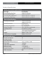
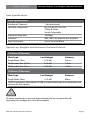
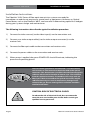
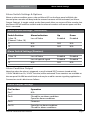
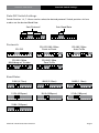
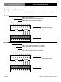
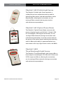
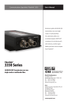
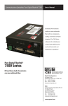
Communications Specialties’ Fiberlink® 3X3X
User’s Manual
The all-digital Fiberlink® 3X3X
series allows you to multiplex
up to 10 video channels along
with optional RS-Type data onto
a single fiber optic core offering
unsurpassed signal distribution
efficiency. Fiberlink 3134 is
compatible with Fiberlink Matrix
offering you the ability to route
up to 320 video signals.
Fiberlink®
3X3X Series
Models 3134/3135 & 3334/3335
10 Channel Video Multiplexer/Demultiplexer
World Headquarters
55 Cabot Court
Hauppauge, New York 11788 USA
Tel: (631) 273-0404
Fax: (631) 273-1638
[email protected]
Asia
Communications Specialties Pte Ltd
100 Beach Road
#22-09 Shaw Tower
Singapore 189702
Tel: +65 6391 8790
Fax: +65 6396 0138
[email protected]
commspecial.com
Fiberlink® 3X3X Series
Contents
Contents
Welcome . . . . . . . . . . . . . . . . . . . . . . . . . . . . . . . . . . . . . . . . . . . . . . . . . . . . . . . . . . . . . . . . . . 3
Features. . . . . . . . . . . . . . . . . . . . . . . . . . . . . . . . . . . . . . . . . . . . . . . . . . . . . . . . . . . . . . . . . . . 3
Package Contents. . . . . . . . . . . . . . . . . . . . . . . . . . . . . . . . . . . . . . . . . . . . . . . . . . . . . . . . . . 3
Technical Specifications
Model Part Number Specifications. . . . . . . . . . . . . . . . . . . . . . . . . . . . . . . . . . . . . 4
General Specifications. . . . . . . . . . . . . . . . . . . . . . . . . . . . . . . . . . . . . . . . . . . . . . . . . 4
Video Specifications. . . . . . . . . . . . . . . . . . . . . . . . . . . . . . . . . . . . . . . . . . . . . . . . . . . 4
Data Specifications. . . . . . . . . . . . . . . . . . . . . . . . . . . . . . . . . . . . . . . . . . . . . . . . . . . . 5
Optical Loss Budgets. . . . . . . . . . . . . . . . . . . . . . . . . . . . . . . . . . . . . . . . . . . . . . . . . . 5
Maximum Useable Distance. . . . . . . . . . . . . . . . . . . . . . . . . . . . . . . . . . . . . . . . . . . 5
Installation Instructions. . . . . . . . . . . . . . . . . . . . . . . . . . . . . . . . . . . . . . . . . . . . . . . . . . . . 6
Alarm Switch Settings. . . . . . . . . . . . . . . . . . . . . . . . . . . . . . . . . . . . . . . . . . . . . . . . . . . . . . 7
Alarm Output Settings. . . . . . . . . . . . . . . . . . . . . . . . . . . . . . . . . . . . . . . . . . . . . . . . . . . . . 7
Data Configuration Procedure. . . . . . . . . . . . . . . . . . . . . . . . . . . . . . . . . . . . . . . . . . . . . . 8
Data DIP Switch Settings. . . . . . . . . . . . . . . . . . . . . . . . . . . . . . . . . . . . . . . . . . . . . . . . . . . 9
Data Terminal Block Wiring. . . . . . . . . . . . . . . . . . . . . . . . . . . . . . . . . . . . . . . . . . . . . . . 10
Operating Pointers. . . . . . . . . . . . . . . . . . . . . . . . . . . . . . . . . . . . . . . . . . . . . . . . . . . . . . . 12
Troubleshooting. . . . . . . . . . . . . . . . . . . . . . . . . . . . . . . . . . . . . . . . . . . . . . . . . . . . . . . . . 12
Maintenance and Repairs . . . . . . . . . . . . . . . . . . . . . . . . . . . . . . . . . . . . . . . . . . . . . . . . 13
Certifications . . . . . . . . . . . . . . . . . . . . . . . . . . . . . . . . . . . . . . . . . . . . . . . . . . . . . . . . . . . . 13
Warranty . . . . . . . . . . . . . . . . . . . . . . . . . . . . . . . . . . . . . . . . . . . . . . . . . . . . . . . . . . . . . . . . 14
Accessories and Related Products . . . . . . . . . . . . . . . . . . . . . . . . . . . . . . . . . . . . . . . . 15
Page 2
Fiberlink® 3X3X Series User’s Manual
Fiberlink® 3X3X Series
Welcome | Features | Package Contents
Welcome
Thank you for purchasing Communications Specialties, Inc.’s Fiberlink® 3X3X Series.
The all-digital Fiberlink® 3134 series allows you to multiplex up to 10 video channels onto a
single fiber optic core offering unsurpassed signal distribution efficiency. Fiberlink 3134 is
compatible with Fiberlink Matrix offering you the ability to route up to 320 video signals.
Fiberlink® 3334 adds RS-Type Data to the same fiber optic cable.
Features
•No adjustments; pure digital processing and transmission
•Full color, uncompressed, real-time transmission in NTSC, PAL or SECAM
•Optional RS-Type Data
•Built-in diagnostic LEDs for each channel and a loss of signal/broken fiber alarm
•Internal, universal power supply with AC line cord
• Fiberlink Matrix Compatible
•One rack unit high (1.75 inches).
• Rackmount ears included with unit
Package Contents
•One Fiberlink® 3134, 3135, 3334 or 3335
•This User’s Manual
• AC Line Cord
• Rackmount Ears
• Accessories Pack (fuses, rubber feet, etc)
Fiberlink® 3X3X Series User’s Manual
Page 3
Technical Specifications
Fiberlink® 3X3X Series
Technical Specifications
Model Part Number Specification
Unit Type
Part Number
Transmitter Box (No Data)
Receiver Box (No Data)
Transmitter Box (With Data)
Receiver Box (With Data)
3134-S7 or 3134-F9
3135-S7 or 3135-F7
3334-S5, 3334-S7 or 3334-F9
3335-S5, 3335-S7 or 3335-F7
General Specifications
Operating Wavelength
Optical Connectors
Operating Temperature
Relative Humidity
Operating Power
Size
Weight
Fiberlink Matrix Compatibe
1310 nm (S Version)
1550 nm (F Version)
ST (S Version)
FCPC (F Version)
0 to +55 degrees C
10% - 90% (non-condensing)
95-250 VAC, 47-63 Hz
1.75 H x 16.75 W x 10 D (inches)
44 H x 425 W x 254 D (mm)
Approx. 5.5 lbs; 2.5 kg
Models 3134 & 3135
Video Specifications
Number of Channels
Number of Fibers
Video Bandwidth
(all channels at rated distance)
Video Input
Input/Outut Impedance
Differential Gain
Differential Phase
Signal-to-Noise Ratio
Video Connectors
Page 4
10
1
10 Hz - 6.5 MHz (-3 dB)
1 volt p-p
75 Ohms
<1.5% typical
<1 degree typical
>63 dB (CCIR weighting)
BNC
Fiberlink® 3X3X Series User’s Manual
Fiberlink® 3X3X Series
Data Specifications | Loss Budgets | Maximum Distance
Data Specifications
Data Specification
Number of Channels
1 (bi-directional)
Interfaces Supported
RS-232, RS-424, RS-485
2 Wire & 4 Wire
Switch Selectable
Maximum Data Rate
100 Kbps
Protocols
NRZ, NRZI, RZ, Manchester, Bi-phase
Data Connectors
Screw Terminal Block
Optical Loss Budgets and Maximum Useable Distance
1310 nm (S Version)
Fiber Type
Single Mode Fiber
Multimode Fiber (62.5u)
Multimode Fiber (50u)
Loss Budget
0-20 dB 0-20 dB 0-20 dB
Distance
55km
1.3km
1.0km
1550 nm (F Version)
Fiber Type
Loss Budget
Distance
Single Mode Fiber
5-23 dB 80km
*Note: A minimum attenuation of 5dB is required between the transmitter and
receiver for this version.
Distance specifications are only approximate and are not guaranteed.
Operating loss budget must not be exceeded.
Fiberlink® 3X3X Series User’s Manual
Page 5
Installation Instructions
Fiberlink® 3X3X Series
Installation Instructions
The Fiberlink® 3X3X Series of fiber optic transmission systems are ready for
immediate use and do not require any special tools or equipment. However, an Optical
Power Meter, such as the Fiberlink® 6615, can be useful in determining optical loss budgets
during your systems design and maintenance.
The following instructions describe the typical installation procedure:
1) Connect the video source(s) to the video input(s) on the transmitter unit.
2) Connect your video output cable(s) to the video output connector(s) on the
receiver unit.
3) Connect the fiber optic cable to the transmitter and receiver units.
4) Connect the power cables to the transmitter and receiver units.
5) When power is applied, the green POWER LED should illuminate, indicating the
presence of operating power.
The transmitting element in the Fiberlink® 3134 transmitter
unit contains a solid state Laser Diode located in the optical
connector. This device emits invisible infrared electromagnetic
radiation which can be harmful to human eyes. The radiation
from this optical connector, if viewed at close range with no
fiber optic cable connected to the optical connector, may be
sufficient intensity to cause instantaneous damage to the
retina of the eye. Direct viewing of this radiation should be
avoided at all times!
CAUTION: RISK OF ELECTRICAL SHOCK
To reduce the risk of electrical shock, do not remove the
cover. No user serviceable parts inside. Refer servicing to
qualified service personnel.
Page 6
Fiberlink® 3X3X Series User’s Manual
Alarm Switch Settings
Fiberlink® 3X3X Series
Alarm Switch Settings & Options
When an alarm condition occurs, the red Alarm LED on the front panel will blink, the
internal piezo sounder will beep and the external contacts will be activated (see Alarm
Output Settings). A toggle switch on the front panel allow you to turn off the sounder, but
the Alarm LED will continue to blink and the external contacts will remain open until the
fault is corrected.
Alarm Switch Settings (Transmitter)
Switch Position
Alarm Indication
Up
Down
1 thru 10
(Channel 1 thru 10)
Loss of Video
Enabled
Disabled
11
N/A
N/A
N/A
12
N/A
N/A
N/A
Alarm Switch Settings (Receiver)
1 thru 10
Loss of Video
Enabled
Disabled
11
Loss of optical signal
Enabled
Disabled
12
N/A
N/A
N/A
Alarm Condition Output
Note that when the alarm is triggered, a set of isolated SPDT contacts (rated at 0.4A,
115VAC 50/60 Hz or 2A, 32 VDC resistive) will be activated. These contacts are available at
the rear panel ALARM terminal block and may be used for remote signaling applications.
Connections to this block are as follows:
Alarm Output Settings
Pin Position
Operation
Pin 7
N/A
Pin 8
Closed for no alarm condition
Open for alarm conditions
Pin 9
Common
Pin 10
Open for no alarm condition
Closed for alarm conditions
Fiberlink® 3X3X Series User’s Manual
Page 7
Data Configuration Procedure
Fiberlink® 3X3X Series
Data Configration Procedure.
The following instructions describe the typical data configuration procedure:
1) Set the rear panel DIP switches of the transmitter for the desired protocol.
See page 9 for DIP switch configuration settings.
2) Set the rear panel DIP switches of the receiver for the desired protocol.
See page 9 for DIP switch configuration settings.
3) Data terminal block positions 1 through 6 can be used as data inputs or data outputs
depending upon the protocol selected. Refer to page 10 for terminal block
configuration.
4) After the terminal blocks have been wire appropriately, plug them into the rear panel
connectors labels DATA/ALARM on both the transmitter and receiver units.
5) If there is no fiber optic cable connecting the transmitter and receiver at this time,
connect an optical cable to both the transmitter and receiver units at this time.
5) Turn on the power for both the transmitter and receiver units. When power is applied
the green POWER LED on each unit will illuminate. TX and RX LEDs are described
below:
TX RX
Transmitter LEDs
RX TX
Receiver LEDs
When illuminated, the
unit is outputting an
optical signal
When illuminated, the
unit is transmitting
return data to the
transmitter unit
When illuminated,
the unit is receiving
return data from the
receiver unit
When illuminated, the
unit is receiving an
optical signal
Page 8
Fiberlink® 3X3X Series User’s Manual
Data DIP Switch Settings
Fiberlink® 3X3X Series
Data DIP Switch Settings
Switch Position 1-3, 7-10 are used to select the desired protocol. Switch positions 4-6 are
used to set the desired Baud Rate.
Sets Protocol
1
2 3 4 5 6 7 8 9 10 11 12
Protocols:
2 3 4 5 6 7 8 9 10 11 12
1
RS-485 4 Wire
Multidrop w/ Tristate
1
2 3 4 5 6 7 8 9 10 11 12
1
2 3 4 5 6 7 8 9 10 11 12
RS-422/485 4 Wire
Point to Point
RS-232
1
Sets Baud Rate
2 3 4 5 6 7 8 9 10 11 12
RS-485 2 Wire
Auto Tx/Rx
1
2 3 4 5 6 7 8 9 10 11 12
RS-485 2 Wire
Zero Tx/Rx
1
2 3 4 5 6 7 8 9 10 11 12
Baud Rates
2400 (4.73ms)
1
2 3 4 5 6 7 8 9 10 11 12
4800 (2.20ms)
1
19.2k (620μsec)
1
2 3 4 5 6 7 8 9 10 11 12
2 3 4 5 6 7 8 9 10 11 12
9600 (1.10ms)
1
38.4k (300μsec)
1
2 3 4 5 6 7 8 9 10 11 12
2 3 4 5 6 7 8 9 10 11 12
57.6k (180μsec)
1
2 3 4 5 6 7 8 9 10 11 12
76.8k (150μsec)
1
2 3 4 5 6 7 8 9 10 11 12
Fiberlink® 3X3X Series User’s Manual
Page 9
Data Terminal Block Wiring
Fiberlink® 3X3X Series
Data Terminal Block Wiring
Pins 1 through 6 are used for data. Pins 7 through 10 are used for the Alarm (see page 7).
RS-232
PIN 1: Signal Common
PIN 2: Signal to be transmitted over fiber
PIN 4: Signal being received from fiber
1 2 3 4 5 6 7 8 9 10
Terminal Block
Receptacle on Unit
DATA
ALARM
Terminal Block
RS-422
PIN 1: Shield Ground
PIN 2: Signal to be transmitted (+) over fiber
PIN 3: Signal to be transmitted (–) over fiber
PIN 4: Signal being received (+) from fiber
PIN 5: Signal being received (–) from fiber
1 2 3 4 5 6 7 8 9 10
Terminal Block
Receptacle on Unit
DATA
ALARM
Terminal Block
Page 10
Fiberlink® 3X3X Series User’s Manual
Data Terminal Block Wiring
Fiberlink® 3X3X Series
RS-485 2 Wire
PIN 1: Shield Ground
PIN 2: Signal to be transmitted/received (+) over/from fiber
PIN 3: Signal to be transmitted/received(–) over/from fiber
1 2 3 4 5 6 7 8 9 10
Terminal Block
Receptacle on Unit
DATA
ALARM
Terminal Block
RS-485 4 Wire
PIN 1: Shield Ground
PIN 2: Signal to be transmitted (+) over fiber
PIN 3: Signal to be transmitted (–) over fiber
PIN 4: Signal being received (+) from fiber
PIN 5: Signal being received (–) from fiber
1 2 3 4 5 6 7 8 9 10
Terminal Block
Receptacle on Unit
DATA
ALARM
Terminal Block
Fiberlink® 3X3X Series User’s Manual
Page 11
Fiberlink® 3X3X Series
Operating Pointers | Troubleshooting
Operating Pointers
Remember to check attenuation of the fiber optic cable. The system will only operate
properly if these specifications fall within the range of the system’s loss budget.
Troubleshooting
Multimode fiber optic cable contains an optical fiber with a light carrying “core” that is
only .0025 inches (62.5 microns) in diameter. Single mode fiber optic cable has an even
smaller “core,” only .00032 to .0004 inches (8-10 microns). This is smaller than a human hair!
Therefore, any minute particles of dirt or dust can easily block the fiber from accepting or
radiating light. To prevent this from happening, always use the provided dust caps when
ever optical connectors are exposed to air. It is also a good idea to gently clean the tip of an
optical connector with a lint-free cloth moistened with alcohol whenever dust is suspected.
The status of the LEDs should provide the first clue as to the origin of any operational
failure. If these are off, it usually means that the fiber is broken or has too much attenuation.
Next, be certain that the input and output signal connections are correct.
An optical power meter, such as the Fiberlink® 6615, a visible light source, such as the
Fiberlink® 6610, and a Three Wavelength Light Source, such as the Fiberlink® 6620, can
greatly assist and expedite troubleshooting of fiber optic transmission systems and are
recommended tools all installers should have available.
Finally, although multimode and single mode devices may look the same, they will not
operate properly together. Using the wrong device or fiber can easily add more attenuation
than specified, resulting in poor overall performance. It should be noted that some of our
fiber optic products support both single mode and multimode fiber in the same unit.
If, after reviewing the above possibilities, the system is still not operating, please contact
the Customer Service Department for further assistance. If you suspect your problem is
caused by the optics or the fiber optic cable, and you have an optical power meter, please
take the appropriate measurements prior to contacting support.
Page 12
Fiberlink® 3X3X Series User’s Manual
Fiberlink® 3X3X Series
Maintenance and Repairs | Certifications
Maintenance and Repairs
The Fiberlink® 3X3X Series has been manufactured using the latest semiconductor devices
and techniques that electronic technology has to offer. They have been designed for long,
reliable and trouble-free service and are not normally field repairable.
Should difficulty be encountered, Communications Specialties maintains a complete
service facility to render accurate, timely and reliable service of all products.
The only maintenance that can be provided by the user is to ascertain that optical
connectors are free of dust or dirt that could interfere with light transmission and that
electrical connections are secure and accurate. Please see the Troubleshooting section of
this manual for additional information.
An optical power meter, such as the Fiberlink® 6615, a visible light source, such as the
Fiberlink® 6610, and a Three Wavelength Light Source, such as the Fiberlink® 6620, can
greatly assist and expedite troubleshooting of fiber optic transmission systems and are
recommended tools all installers should have available.
All other questions or comments should be directed to our Customer Service Department.
It should be noted that many “problems” can easily be solved by a simple telephone call.
If you suspect your problem is caused by the optics or the fiber optic cable, and you have
an optical power meter, please take the appropriate measurements prior to contacting
support.
Certifications
Fiberlink® 3X3X Series User’s Manual
Page 13
Fiberlink® 3X3X Series
Warranty
Communications Specialties, Inc. (CSI) warrants that, for a period of three years after
purchase by the Buyer, this product will be free from defects in material and workmanship
under normal use and service. A Return Material Authorization (RMA) number must be
obtained from CSI before any equipment is returned by the Buyer. All materials must be
shipped to CSI at the expense and risk of the Buyer.
CSI’s obligation under this warranty will be limited, at its option, to either the repair or
replacement of defective units, including free materials and labor. In no event shall CSI be
responsible for any incidental or consequential damages or loss of profits or goodwill.
CSI shall not be obligated to replace or repair equipment that has been damaged by fire,
war, acts of God, or similar causes, or equipment that has been serviced by unauthorized
personnel, altered, improperly installed, or abused.
RMA numbers and repairs can be obtained from:
Communications Specialties, Inc.
55 Cabot Court
Hauppauge, NY 11788 USA
Tel: (631) 273-0404
Fax: (631) 273-1638
or, in the Asia Pacific Region:
Communications Specialties Pte Ltd
100 Beach Road
#22-09 Shaw Tower
Singapore 189702
Tel: +65 6391 8790
Fax: +65 6396 0138
RMA numbers can also be obtained from our web site: commspecial.com
Please have your serial number available.
Page 14
Fiberlink® 3X3X Series User’s Manual
Fiberlink® 3X3X Series
Accessories and Related Products
Fiberlink® 6610 Visible Light Source
The Fiberlink® Visible Light Source provides a
visible 650 nm laser output that can be used for
identifying fiber breaks and individual fibers within
fiber bundles, allowing for convenient, on-site
testing of fiber networks during construction
and maintenance procedures.
Fiberlink® 6615 Optical Power Meter
The Fiberlink® Optical Power Meter measures the
power of optical signals at 850, 980, 1310 and 1550
nm wavelengths, allowing for convenient, on-site
testing of fiber networks during construction and
maintenance procedures. It can be used to measure
the power of an optical signal reaching the receiving
end of a fiber optic cable, as generated either by a
transmitter unit or by a light source such as the 6620.
Fiberlink® 6620
Three Wavelength Light Source
The Fiberlink® Three Wavelength Light Source offers a
laser output at wavelengths of 1310 and 1550 nm and
VCSEL output at 850 nm, allowing for convenient,
on-site testing of fiber networks during construction
and maintenance procedures.
Fiberlink® 3X3X Series User’s Manual
Page 15
Communications Specialties’ Fiberlink® 3X3X
User’s Manual
World Headquarters
Fiberlink®
3X3X Series
Models 3134/3135 & 3334/3335
10 Channel Video Multiplexer/Demultiplexer
55 Cabot Court
Hauppauge, New York 11788 USA
Tel: (631) 273-0404
Fax: (631) 273-1638
[email protected]
Asia
Communications Specialties Pte Ltd
100 Beach Road
#22-09 Shaw Tower
Singapore 189702
Tel: +65 6391 8790
Fax: +65 6396 0138
[email protected]
commspecial.com
©2010 Communications Specialties, Inc.
All Rights Reserved.
Fiberlink and the starburst logo are
registered trademarks of
Communications Specialties, Inc.
CSI and the triangle designs are trademarks
of Communications Specialties, Inc.
P/N 128729 Rev D
©2005 Spectra Vision Productions, Inc.
If y
ba