1
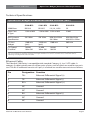
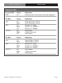
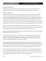
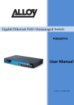
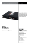
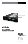
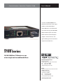
Communications Specialties’ Fiberlink® 5100
User’s Manual
Transmit 10/100/1000 Base-T
Ethernet over one or two single
mode or multimode fibers.
The 5100 Series is full-featured
with auto-sensing 10/100/1000
Mbps Ethernet port with Auto
MDIX and full and half duplex
support. And, of course, the
signal fidelity you have come to
expect from Fiberlink®!
Fiberlink®
5100 Series
10/100/1000 Base-T Etheret over one
or two single mode or multimode fibers.
World Headquarters
55 Cabot Court
Hauppauge, New York 11788 USA
Tel: (631) 273-0404
Fax: (631) 273-1638
[email protected]
Asia
Communications Specialties Pte Ltd
100 Beach Road
#22-09 Shaw Tower
Singapore 189702
Tel: +65 6391 8790
Fax: +65 6396 0138
[email protected]
commspecial.com
Fiberlink® 5100 Series
Contents
Contents
Welcome . . . . . . . . . . . . . . . . . . . . . . . . . . . . . . . . . . . . . . . . . . . . . . . . . . . . . . . . . . . . . . . . . . 3
Features. . . . . . . . . . . . . . . . . . . . . . . . . . . . . . . . . . . . . . . . . . . . . . . . . . . . . . . . . . . . . . . . . . . 3
Package Contents. . . . . . . . . . . . . . . . . . . . . . . . . . . . . . . . . . . . . . . . . . . . . . . . . . . . . . . . . . 3
Technical Specifications
Model Part Number Specifications. . . . . . . . . . . . . . . . . . . . . . . . . . . . . . . . . . . . . 4
General Specifications. . . . . . . . . . . . . . . . . . . . . . . . . . . . . . . . . . . . . . . . . . . . . . . . . 4
Operating Loss Budgets. . . . . . . . . . . . . . . . . . . . . . . . . . . . . . . . . . . . . . . . . . . . . . . 5
Maximum Useable Distance. . . . . . . . . . . . . . . . . . . . . . . . . . . . . . . . . . . . . . . . . . . 5
Ethernet Cable Requirements . . . . . . . . . . . . . . . . . . . . . . . . . . . . . . . . . . . . . . . . . . . . . . 5
Installation Instructions. . . . . . . . . . . . . . . . . . . . . . . . . . . . . . . . . . . . . . . . . . . . . . . . . . . . 6
Indicator LEDs . . . . . . . . . . . . . . . . . . . . . . . . . . . . . . . . . . . . . . . . . . . . . . . . . . . . . . . . . . . . . 7
Operating Pointers. . . . . . . . . . . . . . . . . . . . . . . . . . . . . . . . . . . . . . . . . . . . . . . . . . . . . . . . . 8
Troubleshooting. . . . . . . . . . . . . . . . . . . . . . . . . . . . . . . . . . . . . . . . . . . . . . . . . . . . . . . . . . . 8
Maintenance and Repairs . . . . . . . . . . . . . . . . . . . . . . . . . . . . . . . . . . . . . . . . . . . . . . . . . . 9
Certifications . . . . . . . . . . . . . . . . . . . . . . . . . . . . . . . . . . . . . . . . . . . . . . . . . . . . . . . . . . . . . . 9
Warranty . . . . . . . . . . . . . . . . . . . . . . . . . . . . . . . . . . . . . . . . . . . . . . . . . . . . . . . . . . . . . . . . 10
Accessories and Related Products . . . . . . . . . . . . . . . . . . . . . . . . . . . . . . . . . . . . . . . . 11
Page 2
Fiberlink® 5100 Series User’s Manual
Fiberlink® 5100 Series
Welcome | Features | Package Contents
Welcome
Thank you for purchasing Communications Specialties, Inc.’s Fiberlink® 5100 Series. The
5100 Series is used to transmit 10/100/1000 Base-T Ethernet over one or two single mode
or multimode fiber optic cores. The Fiberlink 5100 Series automatically adapts to the highest level of performance supported by the device connected to the Ethernet port. When the
connected device is a switch or a workstation that supports full-duplex, the Fiberlink 5100
adapts to the full-duplex mode and provides an effective 2000 Mbps bandwidth. When the
connected device is a HUB or a workstation that supports only half-duplex, the Fiberlink
5100 adapts to half-duplex mode providing the nominal 1000 Mbps.
With high performance data transmission and easy installation, the Fiberlink 5100
provides the ultimate ISP network solution for FTTH (Fiber To The Home), FTTC (Fiber To The
Curb) or for ISPs for FTTB (Fiber To The Building), and can also be utilized for small
office network environments.
Features
• Auto-sensing 10/100/1000 Mbps Ethernet port with Auto MDIX
• IEEE 802.3, IEEE 802.3u, IEEE 802.3az, & IEEE 802.3z
• Full-duplex and half-duplex
• LEDs indicate Link Activity, Speed, Fault Detection/Collisions and Power
• Single mode & multimode versions available
• One or Two fiber versions available
• Compact design, wall mountable
Package Contents
• One Fiberlink® 5100 Series Unit
• This User’s Manual
• Mounting Brackets
Fiberlink® 5100 Series User’s Manual
Page 3
Technical Specifications
Fiberlink® 5100 Series
Technical Specifications
Model Part Number Specification
Fibers Unit Type
Part Number 1000-Base-X
1
Single Mode or Multimode (1310/1490 nm) 5100-B7L
BX10-U
1
Single Mode or Multimode (1490/1310 nm) 5101-B7L
BX10-D
2
Single Mode or Multimode (1310 nm)
5102-B7L
LX/LH
2
Multimode (850 nm)
5102-B1L
SX
General Specifications
Maximum Speed (1000Base-Tx/Fx)
Packet Forwarding Rate
Cabling/Maximum Distance
Connectors
LEDs
Launch Power/Receiver Sensitivity
Power Requirements
Operating Temperature Range
Operating and Storage Humidity
Weight
Dimensions
Page 4
Full Duplex: 2000Mbps
Half Duplex: 1000Mbps
14880pps@10Mbps
148800pps@100Mbps
1488000pps@1000Mbps
See Optical Loss Budget &
Maximum Useable Distance sections
of this manual
Copper: RJ-45(Auto-MDI / MDI-X)
Fiber Optic: LC type
TX: LINK/ACT, SPD, FD / COL
FX: LINK/ACT, SPD, FD / COL
Power
1 Fiber SM: -8 dBm min / -23 dBm max
2 Fiber SM: -9 dBm min / -21 dBm max
2 Fiber MM: -9 dBm min / -18 dBm max
Input: 100-240VAC, 50/60Hz
Output: 12V/1A
0 to +50º Celcius
10% to 90% relative humidity
(non-condensing)
2 pounds
4.25” x 3.14 “ x 1.02”
(108mm x 80mm x 26mm)
Fiberlink® 5100 Series User’s Manual
Fiberlink® 5100 Series
Optical Loss Budget | Ethernet Cable Requirements
Technical Specifications
Optical Loss Budget & Maximum Useable Distance (cont.)
5100-B7L
5101-B7L
5102-B7L
5102-B1L
1000-Base-
BX10-U
BX10-D
LX, LH, LH10
SX
Fiber Core
& Type
1 SM or MM
1 SM or MM 2 SM or MM
2 MM
802 Distance
SM 10km
SM 10km
Specification
MM 50u 550m
SM 10km
MM 50u 550m
MM 62.5u 220m
CSI Loss
Budget
15dB min
(pair)
15dB min
(pair)
12dB min
9dB min
CSI Typical
Distance*
1k MM
10km SM
1k MM
10km SM
1k MM
10k SM
1k
*Distance specifications are approximate, based upon connecting a 5100 Transmitter to a 5100 Receiver, and are not guaranteed.
CSI cannot estimate or guarantee operating loss budgets when the 5100 Series is used with other, non-Fiberlink devices.
Operating loss budget must not be exceeded.
Ethernet Cable
The Fiberlink 5100 Series is compatible with standard Category 3, 4 or 5 UTP cable. A
category 5 cable typically consists of four pairs of wires, two of which are used for transmission. The RJ-45 connector consists of 8 pins, 4 of which are used for transmission as follows:
Pin
Designation Function
1
TX+
Ethernet Differential Signal (+)
2
TX-
Ethernet Differential Signal (-)
3
RX+
Ethernet Differential Signal (+)
4
NC
Unused
5
NC
Unused
6
RX-
Ethernet Differential Signal (-)
7
NC
Unused
8
NC
Unused
Fiberlink® 5100 Series User’s Manual
Page 5
Installation Instructions
Fiberlink® 5100 Series
Installation Instructions
The Fiberlink® 5100 Series of fiber optic transmission systems are ready for
immediate use and do not require any special tools or equipment. However, an Optical
Power Meter, such as the Fiberlink® 6615, can be useful in determining optical loss budgets
during your systems design and maintenance.
The following instructions describe the typical installation procedure:
1) Connect the Universal Power Supply to the transmitter and receiver units.
When power is applied, the PWR LED should illuminate, indicating the
presence of operating power.
2) Connect any Category 3, 4 or 5 Ethernet Cable to the Ethernet port of the
transmitting 5100 Series unit. The TX Link LED should illuminate.
3) Connect any Category 3, 4 or 5 Ethernet Cable to the Ethernet port of the
receiver 5100 Series unit. The TX Link LED should illuminate.
4) Connect the fiber optic cable(s) to the transmitter and receiver units.
5) The FX Link LED should illuminate. If the FX Link LED fails to illuminate and you are
using a two fiber system, reverse the fiber optic connections at one of the units.
The transmitting element in the Fiberlink® 5100 transmitter
unit contains a solid state Laser Diode located in the optical
connector. This device emits invisible infrared electromagnetic radiation which can be harmful to human eyes. The
radiation from this optical connector, if viewed at close
range with no fiber optic cable connected to the optical
connector, may be sufficient intensity to cause
instantaneous damage to the retina of the eye. Direct
viewing of this radiation should be avoided at all times!
Page 6
Fiberlink® 5100 Series User’s Manual
Indicator LEDs
Fiberlink® 5100 Series
Indicator LEDs
General LEDs
Status
Definition
PWR
On
Indicates that correct power has been applied.
TX LEDs
Status
Definition
Link
On
Blink
RJ-45 Ethernet is linked
RJ-45 Ethernet is active
SPD
On
Blink
Off
Speed is at 1Gbps
Speed is at 100Mbps
Speed is at 10Mbps
FD/COL
On
Blink
Off
Full-Duplex
Collision occured
Half-Duplex
FX LEDs
Status
Definition
Link
On
Blink
Optical fiber is linked
Optical fiber is active
SPD
On
Blink
Off
Speed is at 1Gbps
Speed is at 100Mbps
Speed is at 10Mbps
FD/COL
On
Blink
Off
Full-Duplex
Collision occured
Half-Duplex
Fiberlink® 5100 Series User’s Manual
Page 7
Fiberlink® 5100 Series
Operating Pointers | Troubleshooting
Operating Pointers
Remember to check attenuation of the fiber optic cable. The system will only operate
properly if these specifications fall within the range of the system’s loss budget.
Troubleshooting
Multimode fiber optic cable contains an optical fiber with a light carrying “core” that is
only .0025 inches (62.5 microns) in diameter. Single mode fiber optic cable has an even
smaller “core,” only .00032 to .0004 inches (8-10 microns). This is smaller than a human hair!
Therefore, any minute particles of dirt or dust can easily block the fiber from accepting or
radiating light. To prevent this from happening, always use the provided dust caps when
ever optical connectors are exposed to air. It is also a good idea to gently clean the tip of an
optical connector with a lint-free cloth moistened with alcohol whenever dust is suspected.
The status of the LEDs should provide the first clue as to the origin of any operational
failure. If these are off, it usually means that the fiber is broken or has too much attenuation.
Next, be certain that the input and output signal connections are correct.
If the FX Link LED fails to illuminate and you are using a two fiber system, reverse the fiber
optic connections at one of the units.
An optical power meter, such as the Fiberlink® 6615, a visible light source, such as the
Fiberlink® 6610, and a Three Wavelength Light Source, such as the Fiberlink® 6620, can
greatly assist and expedite troubleshooting of fiber optic transmission systems and are
recommended tools all installers should have available.
Finally, although multimode and single mode devices may look the same, they will not
operate properly together. Using the wrong device or fiber can easily add more attenuation
than specified, resulting in poor overall performance. It should be noted that some of our
fiber optic products support both single mode and multimode fiber in the same unit.
If, after reviewing the above possibilities, the system is still not operating, please contact
the Customer Service Department for further assistance. If you suspect your problem is
caused by the optics or the fiber optic cable, and you have an optical power meter, please
take the appropriate measurements prior to contacting support.
Page 8
Fiberlink® 5100 Series User’s Manual
Fiberlink® 5100 Series
Maintenance and Repairs | Certifications
Maintenance and Repairs
The Fiberlink® 5100 Series has been manufactured using the latest semiconductor devices
and techniques that electronic technology has to offer. They have been designed for long,
reliable and trouble-free service and are not normally field repairable.
Should difficulty be encountered, Communications Specialties maintains a complete
service facility to render accurate, timely and reliable service of all products.
The only maintenance that can be provided by the user is to ascertain that optical
connectors are free of dust or dirt that could interfere with light transmission and that
electrical connections are secure and accurate. Please see the Troubleshooting section of
this manual for additional information.
An optical power meter, such as the Fiberlink® 6615, a visible light source, such as the
Fiberlink® 6610, and a Three Wavelength Light Source, such as the Fiberlink® 6620, can
greatly assist and expedite troubleshooting of fiber optic transmission systems and are
recommended tools all installers should have available.
All other questions or comments should be directed to our Customer Service Department.
It should be noted that many “problems” can easily be solved by a simple telephone call.
If you suspect your problem is caused by the optics or the fiber optic cable, and you have
an optical power meter, please take the appropriate measurements prior to contacting
support.
Certifications
Fiberlink® 5100 Series User’s Manual
Page 9
Fiberlink® 5100 Series
Warranty
Communications Specialties, Inc. (CSI) warrants that, for a period of three years after
purchase by the Buyer, this product will be free from defects in material and workmanship
under normal use and service. A Return Material Authorization (RMA) number must be
obtained from CSI before any equipment is returned by the Buyer. All materials must be
shipped to CSI at the expense and risk of the Buyer.
CSI’s obligation under this warranty will be limited, at its option, to either the repair or
replacement of defective units, including free materials and labor. In no event shall CSI be
responsible for any incidental or consequential damages or loss of profits or goodwill.
CSI shall not be obligated to replace or repair equipment that has been damaged by fire,
war, acts of God, or similar causes, or equipment that has been serviced by unauthorized
personnel, altered, improperly installed, or abused.
RMA numbers and repairs can be obtained from:
Communications Specialties, Inc.
55 Cabot Court
Hauppauge, NY 11788 USA
Tel: (631) 273-0404
Fax: (631) 273-1638
or, in the Asia Pacific Region:
Communications Specialties Pte Ltd
100 Beach Road
#22-09 Shaw Tower
Singapore 189702
Tel: +65 6391 8790
Fax: +65 6396 0138
RMA numbers can also be obtained from our web site: commspecial.com
Please have your serial number available.
Page 10
Fiberlink® 5100 Series User’s Manual
Fiberlink® 5100 Series
Accessories and Related Products
Fiberlink® 6610 Visible Light Source
The Fiberlink® Visible Light Source provides a
visible 650 nm laser output that can be used for
identifying fiber breaks and individual fibers within
fiber bundles, allowing for convenient, on-site
testing of fiber networks during construction
and maintenance procedures.
Fiberlink® 6615 Optical Power Meter
The Fiberlink® Optical Power Meter measures the
power of optical signals at 850, 980, 1310 and 1550
nm wavelengths, allowing for convenient, on-site
testing of fiber networks during construction and
maintenance procedures. It can be used to measure
the power of an optical signal reaching the receiving
end of a fiber optic cable, as generated either by a
transmitter unit or by a light source such as the 6620.
Fiberlink® 6620
Three Wavelength Light Source
The Fiberlink® Three Wavelength Light Source offers a
laser output at wavelengths of 1310 and 1550 nm and
VCSEL output at 850 nm, allowing for convenient,
on-site testing of fiber networks during construction
and maintenance procedures.
Fiberlink® 5100 Series User’s Manual
Page 11
Communications Specialties’ Fiberlink® 5100
User’s Manual
World Headquarters
Fiberlink®
55 Cabot Court
Hauppauge, New York 11788 USA
Tel: (631) 273-0404
Fax: (631) 273-1638
[email protected]
10/100/1000 Base-T Etheret over one
or two single mode or multimode fibers.
Asia
5100 Series
Communications Specialties Pte Ltd
100 Beach Road
#22-09 Shaw Tower
Singapore 189702
Tel: +65 6391 8790
Fax: +65 6396 0138
[email protected]
commspecial.com
©2009 Communications Specialties, Inc.
All Rights Reserved.
Fiberlink and the starburst logo are
registered trademarks of
Communications Specialties, Inc.
CSI and the triangle designs are trademarks
of Communications Specialties, Inc.
P/N 128107 Rev. A
©2005 Spectra Vision Productions, Inc.
If y
ba