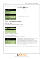
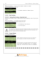
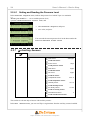
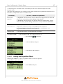
1
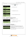
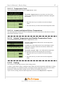
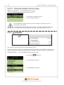
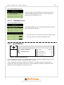
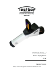
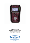
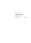
Viper Climate and
Production Computer
User's Manual • Basic-Step
User's Manual • Basic-Step
Program Version
The product described in this manual holds software. This manual corresponds to:
• Software Version CPU 5.5
It was released in December, 2006
Product and Documentation Changes
Big Dutchman reserve the right to change this document and the product herein described without
further notice. In case of doubt, please contact Big Dutchman.
Latest date of change appears from the back page.
IMPORTANT
NOTES CONCERNING THE ALARM SYSTEM
Where climatic control is used in livestock buildings, breakdowns, malfunctions or faulty settings
may cause substantial damage and financial losses. It is therefore most important to install a
separate, independent alarm system, which monitors the house concurrently with the climate
computer. According to EU-directive No. 91/629/EEC and 91/630/EEC an alarm system must be
installed in any house that is mechanically ventilated.
Please note that the product liability clause of Big Dutchman’s general terms and conditions of sale
and delivery specifies that an alarm system must be installed.
In case of misoperation or improper use, ventilation systems can result in production loss
or cause loss of lives among animals.
Big Dutchman recommend that ventilation systems should be mounted, operated and
serviced only by trained staff and that a separate emergency opening unit and an alarm
system be installed as well as maintained and tested at regular intervals, according to Big
Dutchman’s terms and conditions of sale and delivery.
Note
• All rights reserved. No part of this manual may be reproduced in any manner whatsoever
without the expressed written permission of Big Dutchman in each case.
• Big Dutchman have made reasonable efforts to ensure the accuracy of the information
contained in this manual. Should any mistakes or imprecise information occur in spite of
this, Big Dutchman would appreciate being notified hereof.
• Irrespective of the above, Big Dutchman shall not accept any liability with regard to loss or
damage caused or alleged to be caused by reliance on any information contained herein.
• Copyright 2006 by Big Dutchman.
Viper Climate and Production Computer
User's Manual • Basic-Step
1
INTRODUCTION
5
2
USER’S GUIDE
6
2.1
Get started.......................................................................................... 6
2.1.1
Keyboard............................................................................................................................ 6
2.1.2
Display and Menus............................................................................................................ 7
2.1.2.1
2.1.2.2
Outline Screen..................................................................................................................... 7
Function Menus................................................................................................................... 9
2.2
Climate Functions .................................................................................. 10
2.2.1
2.2.1.1
2.2.1.2
2.2.1.3
2.2.2
2.2.2.1
2.2.2.2
2.2.2.3
2.2.3
2.2.3.1
2.2.4
2.2.4.1
2.2.4.2
2.2.5
2.2.5.1
2.2.5.2
2.2.5.3
2.2.6
2.2.6.1
2.2.7
2.2.7.1
2.2.8
2.2.8.1
Control ...................................................................................................................... 10
Room Control.................................................................................................................... 11
Brooding Control .............................................................................................................. 11
Control-Matrix .................................................................................................................. 12
Temperature ............................................................................................................. 15
Inside Temperature............................................................................................................ 15
Outside Temperature and Outside Temperature Curve..................................................... 17
Cooling.............................................................................................................................. 17
Humidity................................................................................................................... 18
Humidity Curve................................................................................................................. 19
Ventilation................................................................................................................. 19
CO2 Minimum Ventilation................................................................................................ 20
Ventilation Status .............................................................................................................. 20
Tunnel ..................................................................................................................... 21
Heat Allowed in Tunnel .................................................................................................... 21
Pad Cooling....................................................................................................................... 22
Tunnel Status..................................................................................................................... 22
Pressure Control....................................................................................................... 23
Setting and Reading the Pressure Level............................................................................ 24
Auxiliary Sensors..................................................................................................... 24
Auxiliary Sensor Curve..................................................................................................... 26
Stir Fan ..................................................................................................................... 26
Setting the Regulation Mode............................................................................................. 27
Viper Climate and Production Computer
User's Manual • Basic-Step
5
1 INTRODUCTION
This user’s manual deals with the operation of the Viper Climate and Production Computer. The user’s
manual provides the user with the fundamental knowledge about the functions of the computer that is
required to ensure optimum use of Viper.
The manual contains a complete description of all the functions of the climate and production
computer. Furthermore, the structure of the manual follows the menu structure of the computer. As the
Viper software is modular software, this manual will contain sections that are irrelevant to the setup of
your computer. If in doubt, please contact Big Dutchman service or your Big Dutchman dealer.
The Viper climate and production computer controls the climate according to the control principle
Basic-Step.
With Basic-Step, the climate is regulated on the basis of P-band regulation. This type of climate
regulation is very flexible for you as a user if you want to be able to influence the setting and
adjustment of several climate functions on a daily basis; however, this also means that you will have to
adjust the climate settings on a daily basis. Temperature and minimum ventilation curves have been
entered. No humidity control is available in Basic-Step.
Viper is a climate and production computer which is capable both of regulating and monitoring the
climate and production in poultry houses.
Big Dutchman would like to congratulate you on your choice of a new
Viper Climate and Production Computer
Viper Climate and Production Computer
6
User's Manual • Basic-Step
2 USER’S GUIDE
2.1
Get started
2.1.1 Keyboard
Main menu key
Outline menu key
• read the outline screen
• gain direct access to setting values
Numeric keyboard
• read the values and settings in the
function menu
• set function menus
Information key
• used to enter values
• the keys 1-4 are used as shortcut keys
when the outline screen is displayed
• gain access to the help menu
Alarm lamp
Quick flashing → alarm
Slow flashing → acknowledged alarm
Constant light → non-acknowledged alarm where
the error has disappeared
Arrow keys and enter key
• with the arrow keys, you can
move around in the menus
• with the enter key, you can
connect or disconnect
functions and accept changes
+, - and C key
• used to change/delete settings
– e.g. when changing the
house name
Display
A scroll panel on the right side
of the display shows you how
long the menu is and where you
are in the menu.
Values, which are readings or calculations, are in normal type.
The values and functions, which
you can change, are highlighted
in bold type.
Viper Climate and Production Computer
User's Manual • Basic-Step
7
2.1.2 Display and Menus
2.1.2.1 Outline Screen
To gain access to the outline screen that provides you with an overview of the current conditions in the
house, press the outline key
once. Here, you can read the values which you will be needing
most often in your work.
→ The icons indicate which menu item is involved
→ The settings can be changed directly from the outline screen
when the setting is selected
Icon
Menu text
Icon
Menu text
Temperature setpoint
Auxiliary sensor
Indoor temperature
Negative pressure
Outside temperature
Effective temperature
Ventilation
Wind speed
Minimum ventilation
Day no.
Alarm
Feed
Zone
Light
Side mode
Light dimmer
Tunnel
Silo
Humidity
Animal weigher
Cooling
Number of animals
Heating
Water
Table 1: Icons in the Outline Screen
2.1.2.1.1 Message line
At the bottom, the display shows a message line, which for instance informs about acknowledged
alarms and the fact that the computer is set to in-between function in connection with cleaning.
The current time and date are indicated farthest to the right.
When, in connection with setup or service, the computer is set to manual regulation of the system,
Viper will indicate the manual control in the message line.
The display reading returns to the outline screen when the computer has not been operated for ten
minutes.
Viper Climate and Production Computer
8
User's Manual • Basic-Step
2.1.2.1.2 Changing a Setting via the Outline Screen,
→ select the required setting (e.g. Temperature
setpoint), and press the enter key
→ change the setting
→ when Yes is highlighted, press to approve and save the
change
or
→ when No is highlighted, press to undo
2.1.2.1.3 Installation Overview via Outline View
The numeric keyboard can help you to get an overview of what has been installed on inputs and
outputs as well as which climate and production functions have been installed.
2.1.2.1.3.1 Outline of Inputs
→ press 1 on the numeric keyboard
From this menu, you can read the values of the individual inputs.
2.1.2.1.3.2 Outline of Climate Functions
→ press 2 on the numeric keyboard
From this menu, you have direct access to change the values set.
(e.g. Temperature setpoint)
2.1.2.1.3.3 Outline of Production Functions
→ press 3 on the numeric keyboard
From this menu, you can read the values of the installed production
functions.
In the right corner of the display an arrow indicates if more
functions are available than shown in the display.
Viper Climate and Production Computer
User's Manual • Basic-Step
9
2.1.2.1.3.4 Outline of Outputs
→ press 4 on the numeric keyboard
From this menu, you can read which functions are
active/inactive.
2.1.2.2 Function Menus
To gain access to reading and setting the menus, press the
main menu key. The Climate,
Production, Management and Alarms menus are for the everyday user while the menus under
Technical have to be changed only if changes are made to the actual installation (if necessary, see the
Technical Manual).
All the Viper functions can be accessed via these menus by
selecting the required function (e.g. Climate), and pressing the
enter key.
(an outline of the functions of the individual menus is provided at the start of each menu section).
Icon
Function
Icon
Function
Setting
Options
Reading
More submenus
Connect
Curve setting
Disconnect
Entering of code/name
Table 2: Operating icons
Viper Climate and Production Computer
10
User's Manual • Basic-Step
2.2 Climate Functions
Control
Temperature
Inside temperature
Outside temperature
Cooling
Humidity
Current humidity
Trend humidity
Lowest humidity 24h
Highest humidity 24h
Ventilation
CO2 min. ventilation
Ventilation status
Pad cooling
Tunnel
Tunnel status
Pressure control
Pressure demand
Pressure setpoint
Pressure regulator actual value
Aux. sensors
Stir fans
Stir fan 1-6
Table 3: Outline of the climate menu
2.2.1
Control
Target temp. (temp.setpoint)
See section 2.2.1.1
concerning setting
of matrix
19 °C
Side control
Room heat
17.5 °C
Room control
Brooding heat
17.5 °C
Brooding control
Start tunnel
27 °C
Stop tunnel
23 °C
Tunnel control
See section
2.2.1.3.2
Timer setup
Table 4: Outline of the control menu
The Control menu gives you access to setting of each side and tunnel fan and each room and
brooding heater by means of matrix menus.
Viper Climate and Production Computer
User's Manual • Basic-Step
11
The menu item Target temp. corresponds to Temperature setpoint in the Temperature
menu (see section 2.2.2.1.1).
The settings of Room heat, Start tunnel and Stop tunnel and Tunnel control depend on
Target temp. Thus, if you change Target temp. by 2 °C, Viper will automatically change these
settings by a corresponding number of degrees.
Example 1:
Dependent temperature settings
Temperature °C
Automatic increase
Start tunnel
Automatic increase
Stop tunnel
Change of Temperature setpoint
Temperature setpoint
Automatic increase
Room heat
Time
If you wish to increase Temperature setpoint without increasing the dependent temperature settings, you must,
after having regulated Temperature setpoint, reduce the settings by the corresponding number of degrees.
2.2.1.1 Room Control
This section is relevant only to houses with heating systems.
In houses with heating systems, the Viper computer adjusts the inside temperature according to the set
temperature and a lower temperature limit.
2.2.1.1.1 House Heaters
Viper controls the heating level of the house according to the climate conditions in the active grow
zone of the house. When only 1/3 and 2/3 of the house are used as grow zone (Grow zone 1 or 2),
Viper can control both the heaters in the active zones and ensure that they run at minimum in the
inactive grow zones. This way, you avoid condensate on the curtains, and the inactive zones are heated
faster when they are to be used as grow zones again. You can use up to six Heaters.
2.2.1.2 Brooding Control
2.2.1.2.1 Brooding Heaters
Viper controls the heating in the brooding zones of the house, independently of the heating level in the
rest of the house. As heating is concentrated around the brooding zones, the house temperature outside
the zones can be kept down to reduce heating consumption. Viper controls the temperature in the
brooding zones and heats them by means of heaters located in each zone. Each heater belongs to a
specific brooding zone, and when you activate a brooding zone, you also activate the heater of the
zone. You can use up to four Brooding heaters.
Viper Climate and Production Computer
12
User's Manual • Basic-Step
2.2.1.3 Control-Matrix
Temp
Current temperature.
If more than one temperature sensors are installed, the value is shown as an average.
For each fan/heater you can specify the following:
ON
Temperature setpoint that activates fan or heater
OFF
Temperature setpoint that stops fan or heater
Timer
Select type of timer function for fan or heater. See section 0.
1-8
Select according to which temperature sensors the individual fan or heater is to be
regulated
I Side control you can also set Spray cooling.
I Tunnel control you can also set PAD cooling.
2.2.1.3.1 Select Timer Function
In each control matrix you can choose between five timer functions (see Table 5).
The graphs in Table 5 corresponds to these settings:
ON-time
60 sec.
Cykle time
300 sec.
ON-temperature
30 °C
OFF-temperature
29 °C
Temperature decreases
Temperature increases
Viper Climate and Production Computer
User's Manual • Basic-Step
Name
(blank line)
No.
At
1
Side fans
Tunnel fans
Spray cooling
PAD cooling
Heat
13
Type
Always ON
Sec.
Side mode
C°
Sec.
Tunnel mode
C°
Minimum timer
2
Side fans
Tunnel fans
ON/OFF
Sec.
C°
Cooling timer
2
Spray cooling
PAD cooling
ON/OFF
Sec.
C°
Ramp
Sec.
C°
Turn on
Stir fan timer
1
2
Side fans
ON/OFF
Tunnel fans
Spray cooling
PAD cooling
House heaters
Brooding
heaters
Side fans
Tunnel fans
ON/OFF
Sec.
C°
Sec.
C°
Ramp
Sec.
C°
Table 5: Setting options for timer functions
Viper Climate and Production Computer
14
User's Manual • Basic-Step
2.2.1.3.2 Set Timer Function
For each timer you must indicate an ON-time and a cycle time and in which mode (ON/OFF, Ramp)
the timer is to run.
When you want to... set a timer,
open the Control menu, and
→ select Timer setup, and press
→ select the required field, and press
→ set a number of seconds
and
→ set a mode
Viper Climate and Production Computer
User's Manual • Basic-Step
2.2.2
15
Temperature
Inside temperature
Temperature setpoint
22.0 °C
Current temp.
21.8 °C
Heat zone 1-6 temp.
18.0 °C
Brooding zone 1-4 temp.
18.0 °C
Trend temperature
Lowest temp. 24 h
Time for lowest temperature
Highest temp. 24 h
Time for highest temperature
Outside temperature
Outside temperature
21.2 °C
05:38:00
22.2 °C
15:43:00
20.7 °C
Trend outside temp.
Lowest outside temp. 24 h
Time for lowest outside temp.
Highest outside temp. 24 h
Time for highest outside temp.
Stop cooling
Cooling
14.2 °C
05:38:00
25.2 °C
15:43:00
85 %
Table 6: Outline of the temperature menu (changeable values are highlighted
in bold types)
2.2.2.1 Inside Temperature
Viper controls the inside temperature according to the set temperature. The house is heated by the heat
generated by the animals and possibly by a heating system.
When the inside temperature is too high, the Viper computer increases ventilation by supplying more
fresh air, and when the temperature is too low, the computer limits ventilation in order to maintain the
heat in the house.
With Viper the house can be divided into three Grow zones. Each grow zone is assigned a number of
temperature sensors to register the temperature in each zone. According to the age and the size of the
animals Viper activates the zones (see the menu Technical / Setup / Adjustment / Climate /
Configuration in the Technical manual regarding setting of number of grow zones).
When the individual temperature sensor has been assigned to a zone, it will be active only when the
associated zone is active. Thus, the sensors in Grow zone 2 and 3 are inactive when Grow
zone 2 and 3 are inactive. Viper’s temperature indication therefore depends on which grow zone
is active.
Viper Climate and Production Computer
16
User's Manual • Basic-Step
All menu items … in the temperature menu Inside
temperature can be set by
→ pressing the
menu key
→ select Climate, and press
→ select Temperature, and press
→ select Inside temperature, and press
2.2.2.1.1 Setting the Temperature Setpoint
When you want to … set the temperature,
open the Climate/Temperature/Inside temperature menu, and
→ select Temperature setpoint, and press
→ set the temperature, and press
2.2.2.1.2 Brooding Zone Temperature
The Climate/Temperature/Inside temperature menu
With Viper the house can be divided into three grow zones.
Grow zone 1 can be divided into several smaller zones,
brooding zones, where the heat is concentrated around a smaller
area in the grow zone.
Viper controls the temperature in the brooding zones and heats
them by means of heaters.
Viper Climate and Production Computer
User's Manual • Basic-Step
17
2.2.2.1.3 Temperature Curve
The Climate/Temperature/Inside temperature menu.
The Trend temperature curve provides you with a clear
picture of the temperature development in the house during the
last 24 hours.
→ Press the arrow keys to read the exact time and figure
values.
→ Press the enter key to return to the inside temperature menu.
2.2.2.1.4 Lowest and Highest 24-hour Temperatures
The 24h temperatures indicate the lowest and highest measured temperatures within the last 24 hours
and the time when they occurred.
2.2.2.2 Outside Temperature and Outside Temperature Curve
The Climate/Temperature/Outside temperature menu.
Outside temperature indicates the current temperature
outside the house.
In addition, the Viper indicates the lowest and highest outside
temperature measured within the last 24 hours and the time
when they occurred.
The Trend outside temp. curve indicates the temperature
development outside the house during the last 24 hours.
→ Press the arrow keys to read the exact time and figure
values.
→ Press the enter key to return to the outside temperature
menu.
2.2.2.3 Cooling
This section is relevant only to houses with cooling systems.
Cooling is used in houses where ventilation cannot reduce the inside temperature sufficiently. Cooling
has the advantage over ventilation in that it can bring the inside temperature down below the outside
temperature. On the other hand, cooling will also increase air humidity in the house.
Viper activates cooling when the inside temperature rises above the Temperature setpoint.
Viper Climate and Production Computer
18
User's Manual • Basic-Step
2.2.2.3.1 Setting the Humidity Limit for Cooling
When you want to … set a humidity limit for cooling,
open the Climate/Temperature/Cooling menu, and
→ select Stop cooling, and press
→ set a percentage, and press
The combination of a high inside temperature and high air humidity can be life
threatening to the animals.
As cooling makes the house humidity increase, Viper will automatically disconnect
cooling when the house humidity exceeds Stop cooling (normally 75-85 %).
2.2.3
Humidity
Current humidity
74 % RH
Trend humidity
Lowest humidity 24 h
72 %
Highest humidity 24 h
76 %
Table 7: Outline of the humidity menu
This section is relevant only to houses with humidity sensors.
The Viper computer can show you the humidity content of the house air. Humidity is supplied to the
house air partly from animals, feed, drinking water and litter, and partly from the cooling function.
All menu items … under the Humidity menu can be read by
→ pressing the
menu key
→ select Climate, and press
→ select Humidity, and press
Viper Climate and Production Computer
User's Manual • Basic-Step
19
The Climate/Humidity menu
Viper shows the current humidity level of the house air in the
Current humidity menu on the basis of the registrations
made by the house humidity sensor.
2.2.3.1 Humidity Curve
The Climate/Humidity menu
The Trend humidity curve indicates the humidity level in the
house during the last 24 hours.
→ Press the arrow keys to read the exact time and figure values
→ Press the enter key to return to the humidity menu
2.2.4
Ventilation
CO2 min. ventilation
CO2
Ventilation status
Side inlet 1-6
49 %
Side stage 1-16
OFF
MultiStep 1-8
OFF
3000 ppm
Table 8: Outline of ventilation menu
The house ventilation consists of an air inlet and an air outlet. Apart from supplying fresh air to the
house, ventilation is to remove any humidity and excess heat.
Viper continuously adjusts the ventilation according to a calculation of the current ventilation
requirement. Thus, the computer will increase or limit ventilation according to whether the inside
temperature and air humidity are too high or too low.
Viper Climate and Production Computer
20
User's Manual • Basic-Step
All menu items … in the Ventilation menu can be read by
→ pressing the
menu key
→ select Climate, and press
→ select Ventilation, and press
2.2.4.1 CO2 Minimum Ventilation
2.2.4.1.1 CO2
This section is relevant only to houses with CO2 sensor.
The Climate/Ventilation/CO2 min. ventilation menu
In the CO2 menu, you can see the content of CO2 in the house
air.
2.2.4.2 Ventilation Status
2.2.4.2.1 Flap Opening
The Climate/Ventilation/Ventilation status menu
The flap opening is a percentage indication of how much the
flaps of both the air inlet and the air outlet are open.
If you are in doubt about the actual ventilation output, you can
compare the reading of the ventilation status in the ventilation
menu with the output that you can actually observe in the house.
Thus, the percentage indications are particularly relevant in
connection with fault finding.
Viper Climate and Production Computer
User's Manual • Basic-Step
2.2.5
21
Tunnel
Heat allowed in tunnel
Pad cooling
Humidity limit
Pad temperature
Tunnel status
85 %
22.0 °C
Tunnel inlet 1-2
0%
Tunnel stage 1-16
OFF
Tunnel MultiStep 1-8
OFF
Table 9: Outline of the tunnel menu (changeable values are highlighted in bold types)
This section is relevant only to houses with tunnel ventilation.
Tunnel ventilation is used at high temperatures and when the air intake through wall inlets and curtains
is insufficient to keep the animals chilled. For tunnel ventilation, air is taken in through a pad cooling
system located at one end of the house. Air is vented out through several gable fans at the other end of
the house, which makes the air move in a lengthwise direction in the house. The high air speed in the
house provided by the gable fans and the effect of the pad cooling reduce the temperature in the house.
Pads are kept moist through recirculation of water, and the gable fans automatically draw fresh air
through the moist pads and absorb water vapour from them.
The high air speed at tunnel ventilation makes the measured temperature feel colder, making it more
comfortable for the animals.
All menu items … in the Tunnel
menu can be read and set by
→ pressing the
menu key
→ select Climate, and press
→ select Tunnel, and press
2.2.5.1 Heat Allowed in Tunnel
When heating is required in houses ventilated by means of tunnel ventilation only, you can connect the
Heat allowed in tunnel function.
Viper Climate and Production Computer
22
User's Manual • Basic-Step
When you want to … connect or disconnect Heat
allowed in tunnel,
open the Climate/Tunnel menu, and
→ select Heat allowed in tunnel, and press
2.2.5.2 Pad Cooling
2.2.5.2.1 Setting Stop Cooling - Humidity Limit
When the house humidity is equal to or higher than the setting for Humidity limit, Viper stops pad
cooling.
When you want to … set a humidity limit for pad cooling,
open the Climate/Temperature/Pad cooling menu, and
→ select Humidity limit, and press
→ set a value, and press
The combination of a high house temperature and high air humidity can be life threatening
to the animals. Pad cooling should, therefore, be disconnected when air humidity is very
high since cooling will increase air humidity further.
2.2.5.3 Tunnel Status
The Climate/Tunnel menu
Tunnel ventilation consists partly of one or two stepless air
inlets, and partly of a number of ON/OFF exhaust units.
The flap opening is a percentage indication of how much the
tunnel air inlet is open (Tunnel inlet 1 / 2). At Tunnel
stage fan, the exhaust units are either on or off (ON/OFF).
Viper Climate and Production Computer
User's Manual • Basic-Step
2.2.6
23
Pressure Control
Pressure requirement
0%
Pressure setpoint
20 Pa
Pressure regulator actual value
20 Pa
Table 10: Outline of the pressure control menu (changeable values are
highlighted in bold types)
This section is relevant only to houses with pressure sensors.
By means of a pressure sensor, the Viper computer can control the pressure level in the house. On the
basis of the sensor measurements, Viper controls the opening of the flaps; in this way, it maintains the
required pressure level in the house (Pressure setpoint).
All menu items … in the Pressure
control menu can be set and read by
→ pressing the
menu key
→ select Climate, and press
→ select Pressure control, and press
The Climate/Pressure control menu
The Pressure requirement menu item is a percentage
indication of how much the flaps in the active grow zone are to
be open to maintain the Pressure setpoint.
Viper Climate and Production Computer
24
User's Manual • Basic-Step
2.2.6.1 Setting and Reading the Pressure Level
In the Pressure setpoint menu, indicate the pressure level which Viper is to maintain.
When you want to … set or read the pressure level,
open the Climate/Pressure control menu, and
→ select Pressure setpoint, and press
→ set a value, and press
You can read the current pressure level in the house under the
menu item Pressure actual value.
2.2.7
Auxiliary Sensors
Aux. sensor 1-4
CO2 sensor
3000 ppm
Trend CO2-sensor
Press. sensor
20 pa
Trend pressure sensor
NH3 sensor
0 ppm
Trend NH3-sensor
O2 sensor
0 ppm
Trend O2 sensor
Temperature sensor
22.0 °C
Trend temperature sensor
Humidity sensor
74.0 %
Trend humidity sensor
Air velocity sensor
1.5 m/s
Trend air velocity sensor
Wind direction sensor
0
Trend wind direction sensor
Table 11: Outline of the auxiliary sensors menu
This section is relevant only to houses with auxiliary sensors.
In the Aux. sensors menu, you can read Viper’s registrations from the auxiliary sensors installed.
Viper Climate and Production Computer
User's Manual • Basic-Step
25
CO2, pressure, NH3, O2, temperature, humidity, air speed and wind direction sensors can be connected.
Viper can be connected to up to four auxiliary sensors; the Aux. sensors menu display depends on
which types of auxiliary sensors you install.
All menu items … in the Aux.
sensors menu can be read by
→ pressing the
menu key
→ select Climate, and press
→ select Aux. sensors, and press
When you want to … read the current value of an auxiliary sensor;
open the Climate/Aux. sensors menu, and
→ select Aux. sensor 1, and press
→ read the sensor registration
Repeat the reading for the installed number of sensors.
Viper Climate and Production Computer
26
User's Manual • Basic-Step
2.2.7.1 Auxiliary Sensor Curve
The auxiliary sensor trend curve indicates the registrations from the auxiliary sensor during the last 24
hours.
When you want to … read the trend curve,
open the Climate/Aux. sensors/Aux. sensor 1, and
→ select Trend xxx. sensor, and press
→ Press the arrow keys to read the exact time and figure values
→ Press the enter key to return to the Aux. sensor 1 menu
Repeat the reading for the installed number of sensors.
2.2.8
Stir Fan
Stir fan 1-6
Mode
Heater
Temperature
24-hour clock
Heater
Control
Together
Separate
Start delay
Together
Stop delay
Seperate
Runtime
Temperature
Control
One sensor
Two sensors
Sensors installed
Sensor no.
One sensor
High temp. sensor no.
Two sensors
Low temp. sensor no.
Stir fan temp.
ON-time
OFF-time
24-hour clock
Start time
Stop time
ON-time
OFF-time
Table 12: Survey of the menu for stir fans (changeable values are highlighted in bold types).
Viper Climate and Production Computer
User's Manual • Basic-Step
27
A stir fan improves circulation of the air and thus provides a more uniform temperature in the
livestock house.
The Viper can regulate up to six stir fans at a time. Each stir fan can be regulated in connection with a
heat source, a temperature sensor or a 24-hour clock.
Controller
Heat source
(up to 6)
Stir fan – method of operation
1) Together: The stir fan runs while the heat source supplies heat, but starts and
stops with a set time delay (Start delay/Stop delay).
2) Separate: The stir fan runs after the heat source has supplied heat. It starts
with a time delay (Start delay) and runs for a set period of time (Runtime).
Temperature
sensor (up to 2)
1) One temperature sensor: The stir fan runs for a set ON-time, when the
temperature deviates more than set in Temperature setpoint.
2) Two temperature sensors: The stir fan runs for a set ON-time at a set
temperature difference between the two sensors.
24-hour clock
1) The stir fan runs for a set ON/OFF-time at set times.
All menu items … in the menu Stir
fan can be observed and set by
→ pressing the
menu key
→ select Climate, and press
→ select Stir fan, and press
2.2.8.1 Setting the Regulation Mode
When you want to... opt for a regulation mode for a stir fan, open the
Climate/Stir fan menu, and
→ select Mode, and press
Viper Climate and Production Computer
28
User's Manual • Basic-Step
→ select the required mode
2.2.8.1.1 Regulation of the Heat Source
When the stir fan is to operate in connection with heat sources, you must opt for a way to control and
set the start and stop time of the fan.
Example 2:
Heat source regulation
Way to control: Separate
Stop delay
Heater
Stir fan
Start delay
Way to control: Together
Start delay
Runtime
Time
2.2.8.1.1.1 Setting the Way to Control
When you want to... opt for a way to control in connection with heat source, open the
Climate/Stir fan/Stir fan x menu, and
→ select Control, and press
→ select the required way of control
Viper Climate and Production Computer
User's Manual • Basic-Step
29
2.2.8.1.1.2 Setting Runtime for Stir Fan
When you want to... set a runtime for the stir fan, open the
Climate/Stir fan menu and
→ select Start delay, and press
→ set an interval
The Stop delay (Together) or Runtime (Separate) should be set in the same way.
2.2.8.1.2 Temperature Sensor Regulation of the Stir Fan
When a stir fan should operate in connection with temperature sensors, you have to set how many (one
or two) and according to which sensors the computer should control and the temperature activating the
stir fan.
Example 3:
Temperature sensor regulation
Temperature
Stir fan temp.
ON-time
OFF-time
2 °C
5 min.
5 min.
Stir fan temperature
Time
One sensor: Stir fan temp. is a deviation from Temperature setpoint.
Two sensors: Stir fan temp. is a temperature difference between the two sensors.
2.2.8.1.2.1 Setting the Way of Control
When you want to... opt for a way to control, open the
Climate/Stir fan menu, and
→ select Control, and press
→ set the number of temperature sensors
2.2.8.1.2.2 Selecting Temperature Sensor
You have to select according to which of the installed temperature sensors Viper should regulate the
stir fan.
Viper Climate and Production Computer
30
User's Manual • Basic-Step
When you want to... select temperature sensor, open the
Climate/Stir fan menu, and
→ select Sensor no., and press
→ select temperature sensor
The High/low temp. sensor no. should be set in the same way, when the Viper regulates
according to two temperature sensors.
NB
If you select a sensor number higher than the number of sensors actually installed, Viper will
not accept the setting.
2.2.8.1.2.3 Setting the Temperature for Stir Fan
One temperature sensor The computer activates the stir fan when the inside temperature deviates
from Temperature setpoint with the number of degrees set in the
Stir fan temperature menu.
Two temperature sens. The computer activates the stir fan when the temperature difference
between the two sensors exceeds the number of degrees set in the Stir
fan temperature menu.
When you want to... set a temperature for the stir fan, open the
Climate/Stir fan menu, and
→ select Stir fan temperature, and press
→ set a number of degrees/a temperature
2.2.8.1.2.4 Setting of ON and OFF-Time for Stir Fan
When you want to... set a runtime for the stir fan, open the
Climate/Stir fan menu, and
→ select ON-time, and press
→ set an interval
The OFF-time should be set in the same way.
2.2.8.1.3 24-Hour Regulation of the Stir Fan
When the stir fan is to operate in connection with a 24-hour clock, you have to make the time setting
as to when it should start and stop within the ON/OFF-time.
Viper Climate and Production Computer
User's Manual • Basic-Step
Example 4:
31
24-hour clock regulation
Temperature
Start time
Stop time
ON-time
OFF-time
14:00 h:m
16:00 h:m
5 min.
5 min.
Time
2.2.8.1.3.1 Setting an Active Interval for the Stir Fan
When you want to... set an interval for the stir fan, open the
Climate/Stir fan menu, and
→ select Start time, and press
→ set an interval
The Stop time should be set in the same way.
2.2.8.1.3.2 Setting of ON and OFF-Time for Stir fan
The setting is carried out in the same way as for temperature regulation. See section 2.2.8.1.2.4.
Viper Climate and Production Computer
2006.12.01 • 609121-02 • 9.15 • EN
BIG DUTCHMAN International GmbH • Calveslage • Auf der Lage 2 • 49377 Vechta
Tel. 04447/801-0 • Fax 04447/801-237