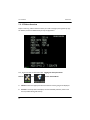
1
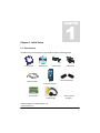
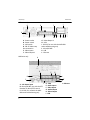
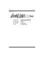
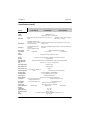
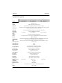
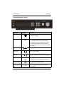
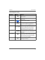
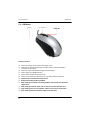
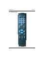
DVR Manual Version 10
(Beta)
Copyright Mace Security International 2008
DVR Manual
Table of Contents
Table of Contents
Page
Introduction
Chapter 1 - Initial Setup.……………………………………………………………………………………1
1.1 - Box Contents…………………………………………………………………………………………………………1
1.2 - Operating Conditions……………………………………………………………………….....……………….2
1.3 - Back Panel Introduction………………………………………………………………………………………..3
1.4 - Specifications………………………………………………………………………………………………………..6
Chapter 2 - System Navigation…………………………………………………………..10
2.1 - Front Panel Operation………………………………………………………………..……………………….10
2.2 - USB Mouse………………………………………………………………………………………………………….15
2.3 - IR Remote Control……………………………………………………………………………………………….17
Chapter 3 - Basic Settings………………………………………………………………….19
3.1 - Logging into the System Menu…………………………………………………………………………….19
3.2 - System Settings…………………………………………………………………………………………………..20
3.3 - General……………………………………………………………………………………………………………….22
3.4 - Encode………………………………………………………………………………………………………………..24
3.5 - Schedule……………………………………………………………………………………………………………..28
3.6 - Display………………………………………………………………………………………………………………..30
Chapter 4 - Searching Video………………….…………………………………………..32
4.1 - Search Menu……………………………………………………………………………………………………….32
4.2 - Playback Bar………………………………………………………………………………………………………..34
4.3 - Advanced Search Features…………………………………………………………………………………..36
Chapter 5 - Backup Video………………………………………………………………….38
5.1 - Backup Media……………………………………………………………………………………………………..38
v
Table of Contents
DVR Manual
5.2 - Backup Menu………………………………………………………………………………………………………39
5.2.1 - RT3 Style Menu…………………………………………………………………………………..39
5.2.2 - HP/RT2 Style Menu…………………………………………………………………………….43
5.3 - Mace Player………………………………………………………………………………………………………..45
5.3.1 - Player Installation………………………………………………………………………..…….45
5.3.2 - Using the Mace Player………………………………………………………………………..48
5.4 - Advanced Player Features…………………………………………………………………………………..50
Chapter 6 - Networking……………………………………………………………………..51
6.1 - Network Menu…………………………………………………………………………………………………….51
6.2 - Networking 101…………………………………………………………………………………………………..54
6.3 - Port Forwarding/NAT…………………………………………………………………………………………..60
6.4 - Pro Surveillance System………………………………………………………………………………………63
6.4.1 - Pro Surveillance System Installation…………………………………………………..64
6.4.2 - Using the Pro Surveillance System………………………………………………………66
6.5 - Remote Client……………………………………………………………………………………………………..70
6.5.1 - Remote Client Installation…………………………………………………………………..71
6.5.2 - Using the Remote Client……………………………………………………………………..73
6.6 - Troubleshooting………………………………………………………………………………………………….76
Chapter 7 - PTZ Installation……………………………………………………………….78
7.1 - Connections………………………………………………………………………………………………………..78
7.2 - PTZ Menu…………………………………………………………………………………………………………….81
7.3 - Control………………………………………………………………………………………………………………..83
7.3.1 - Using the DVR’s GUI……………………………………………………………………………83
7.3.2 - Using Internet Explorer………………………………………………………………………88
7.3.3 - Using Pro Surveillance System…………………………………………………………….90
7.4 - Troubleshooting………………………………………………………………………………………………….91
Chapter 8 - Other Settings…………………………………………………………………93
8.1 - Display………………………………………………………………………………………………………………..93
8.2 - Motion Detection………………………………………………………………………………………………..95
8.3 - Alarm I/O…………………………………………………………………………………………………………….98
8.4 - RS-232…………………………………………………………………………………………………………………99
iv
DVR Manual
Table of Contents
Chapter 9 - Advanced Settings…………………………………………………………102
9.1 - HDD Management…………………………………………………………………………………………….102
9.2 - Alarm Output…………………………………………………………………………………………………….105
9.3 - Alarm Input………………………………………………………………………….…………………………...105
9.4 - Manual Record………………………………………………………………………………………………….106
9.5 - Accounts……………………………………………………………………………………………………………107
9.6 - Auto Maintenance…………………………………………………………………………………………….111
9.7 - TC Adjust…………………………………………………………………………………………………………..111
9.8 - Color Setting……………………………………………………………………………………………………..112
Chapter 10 - Troubleshooting………………………………………………………….114
10.1 - Information Menu…………………………………………………………………………………………..114
10.1.1 - HDD Info………………………………………………………………………………………...114
10.1.2 - BPS…………………………………………………………………………………………………116
10.1.3 - System Log……………………………………………………………………………………..117
10.1.4 - System Version……………………………………………………………………………….119
10.1.5 - Online Users…………………………………………………………………………………..120
FAQs………………………………………………………………………………………………121
iii
Chapter 1 - Initial Setup
1.1 - Box Contents
Included in the accessory box of your DVR will be the following items:
User Manual
Software CD
Power Cable
USB Mouse
Mounting Brackets
Network Cable
IR Remote Control
PTZ Decoder*
Audio Dongle
Video Loop Out
Dongle**
*400RT2, 800RT2 and 56MR models only
**RT3 models only
1
Initial Setup
DVR Manual
1.2 - Operating Conditions
Working Temperature 50° - 131° F
Working Relative Humidity 10% - 90%
Using a UPS (Uninterruptible Power Supply) with surge and battery backup is
strongly recommended for DVRs and all associated devices (routers, modems,
etc.)
•
•
•
•
•
•
•
•
Avoid extreme heat
Avoid direct sunlight
Avoid excessive humidity
Maintain horizontal mounting
Avoid excessive vibrations
Do not place other devices on top of the DVR
Operate in a well ventilated place
Do not block the cooling fan
Before Powering Up
♦
♦
2
Make sure the orange tab on the power supply is set to 115V
Plug power supply into a reliable 110VAC power source
DVR Manual
Initial Setup
1.3 - Back Panel Introduction
DVR-400HP, DVR-400RT2 and DVR-800RT2 only
B
E
I
L
A
C
D
F G H J
A - Power socket
B - Power switch
C - VAC switch
D - RS-232, for use with the MSP-KBD
and troubleshooting only
E - Alarm/RS-485, use with the PTZ
Decoder for Alarm/PTZ control
K
F - VGA
G - USB
H - Ethernet
I - Audio Output
J - Video Output
K - Video Inputs
L - Audio Inputs
DVR-800HP, DVR-1600HP and DVR-1600RT2 only
D
B
J
F
A
C
A - Power socket
B - Power switch
C - VAC switch
D - DB-25 Audio Dongle
connection
E - Video Inputs
F - Video Output 1
E
G H
I
K L
G - Video Output 2
H - VGA
I - RS-232, for use with the MSP-KBD
and troubleshooting only
J - Alarm/RS-485
K - USB
L - Ethernet
3
Initial Setup
DVR Manual
RT3 Series only
D
B
J
F
A
C
A
D
E
G
B
J
I
C
A - 12V Power Input
B - Alarm/RS-485, use with the PTZ
Decoder for Alarm/PTZ control
C - RS-232, for use with the MSPKBD and troubleshooting only
4
K L
I
G - Video Output 2
H - VGA
I - RS-232, for use with the MSP-KBD
and troubleshooting only
J - Alarm/RS-485
K - USB
L - Ethernet
A - Power socket
B - Power switch
C - VAC switch
D - DB-25 Video Loop
Out connection
E - Video Inputs
F - Video Output 1
MR Series only
G H
E
H
F D - VGA
E - Audio Inputs
F - Video Inputs
G - Audio Output
H - Video Output
I - USB
J - Ethernet
DVR Manual
Initial Setup
MM Series only
A
E
C
F
H
J
K
B
D
A - Audio Inputs
B - Video Inputs
C - Audio Outputs
D - Video Outputs
E - AUX Audio
F - VGA
G
I
G - RS-232 for use with the MSP
-KBD and troubleshooting only
H - Ethernet
I - USB
J - Alarm/RS-485
K - 12V Power Input
5
Initial Setup
DVR Manual
1.4 - Specifications
Detail
DVR-400RT2
DVR-800RT2
DVR-1600RT2
Operating
System
Embedded Linux OS
Interface
USB Mouse, IR Remote, Front Panel GUI
Video Input
4/8 Channel Composite video (NTSC/PAL) BNC (1.0Vp-p, 75
Ohms)
Video Output
2 PAL/NTSC composite video outputs,
1 PAL/NTSC composite video output, BNC (1.0Vp-p, 75 Ohms) 1 BNC (1.0Vp-p 75 Ohms) 1 VGA Monitor
VGA monitor output
output
Audio Input
4 channel 200-1000mv 10K
Ohms (BNC)
Audio Output
Video Display
Video
Standard
System
Resource
Image Resolution
Video Recording
Rate
8 channel 200-1000mv 10K
Ohms (BNC)
1 Channel 2000mv 1K Ohms (BNC)
1, 4 Windows
16 Channel composite video (NTSC/PAL)
BNC (1.0Vp-p , 75 Ohms)
16 channel 200-1000mv 10K Ohms (RCA)
1 Two-Way audio communication RCA
1 Channel 200-3000mv 5K Ohms (BNC)
1, 4, 9 Windows
1, 4, 9, 16 Windows
NTSC 525 Lines 60F/s, PAL 625 Lines 50F/s
Real-time recording, single channel playback and simultaneous network
playback (Triplex)
NTSC/PAL Real-Time Monitor D1
704x480/704x576, Playback CIF
NTSC/PAL Real-Time Monitor D1 704x480/704x576, Playback
352x240/352x288
HD1 352x480/352x576, CIF 352x240/352x288
NTSC 1F/s - 30F/s, PAL 1F/s - 25F/s Adjustable
Video Image Quality
6 Different Levels
Video Compression
MPEG-4/H.264
Audio Compression
PCM
Hard Disk Capability
4 Internal IDE Ports, Maximum 8 HDDs
Hard Disk Usage
Video 56 - 900MB/Hr Audio28.8MB/Hr
Network Interface
Pan-Tilt Control
Back-Up Methods
Alarm Input
Alarm Output
Alarm Relay
Power Supply
Power Consumption
Working
Temperature
Relative Humidity
Barometric Pressure
Size
Weight
6
RJ-45 10/100M Ethernet Connection
RS-485/Selectable Protocol
CD/DVD Drive, USB Drive, Network Download
8-Channel Voltage alarm Input
16-Channel Voltage Alarm Input
3-Channel Relay Output (1 Channel Controllable, 12V Output)
6-Channel Relay Output
30VDC 2A, 125VAC 0.5A Relay Output
30VDC 2A, 125VAC 1A Relay Output
220V+/-25%, 50+/-2% Hz, 110V 60Hz
25W (No HDD)
40W (No HDD)
14 F - 131 F
10% - 90%
86kpa - 106kpa
2U Standard Industrial Case, 441mm x 430mm x 89mm (W x D x H)
24lb. (No HDD)
DVR Manual
Initial Setup
Specifications (cont’d)
Detail
DVR-400HP
DVR-800HP
DVR-1600HP
Operating
System
Embedded Linux OS
Interface
USB Mouse, IR Remote, Front Panel GUI
Video Input
4/8 Channel Composite video (NTSC/PAL) BNC (1.0Vp-p, 75
Ohms)
Video Output*
1 PAL/NTSC composite video
output, BNC (1.0Vp-p, 75 Ohms) 2 PAL/NTSC composite video outputs, BNC (1.0Vp-p 75 Ohms) 1 VGA
1 VGA monitor output
Monitor output
Audio Input
Audio Output
Video Display
4 channel 200-1000mv 10K
Ohms (BNC)
1 Channel 2000mv 1K Ohms
(BNC)
8\16 channel 200-1000mv 10K Ohms (RCA) 1 Two-Way audio communication RCA
1 Channel 200-3000mv 5K Ohms (BNC)
1, 4 Windows
1, 4, 9 Windows
Video
Standard
System
Resource
Image Resolution
Video Recording
Rate
1, 4, 9, 16 Windows
NTSC 525 Lines 60F/s, PAL 625 Lines 50F/s
Real-time recording, single channel playback and simultaneous network
playback (Triplex)
NTSC/PAL Real-Time Monitor D1 704x480/704x576, Playback CIF 352x240/352x288
NTSC 1F/s - 7F/s, PAL 1F/s - 7F/s Adjustable
Video Image Quality
6 Different Levels
Video Compression
MPEG-4/H.264
Audio Compression
ADPCM
2 internal IDE Ports, Maximum 4
Hard Disk Capability
HDDs
Hard Disk Usage
RJ-45 10/100M Ethernet Connection
Pan-Tilt Control
RS-485/Selectable Protocol
Back-Up Methods
Alarm Output
Alarm Relay
Power Supply
Power Consumption
Working
Temperature
Relative Humidity
Barometric Pressure
Size
Weight
4 Internal IDE Ports, Maximum 8 HDDs
Video 56 - 900MB/Hr Audio28.8MB/Hr
Network Interface
Alarm Input
16 Channel composite video (NTSC/PAL)
BNC (1.0Vp-p , 75 Ohms)
CD/DVD Drive, USB Drive, Network Download
8-Channel Voltage alarm Input
3-Channel Relay Output (1
Channel Controllable, 12V)
20W (No HDD)
16-Channel Voltage Alarm Input
6-Channel Relay Output
30VDC 2A, 125VAC 1A Relay Output
220V+/-25%, 50+/-2% Hz, 110V 60Hz
30W (No HDD)
40W (No HDD)
14 F - 131 F
10% - 90%
86kpa - 106kpa
2U Standard Industrial Case, 441mm x 430mm x 89mm (W x D x H)
24lb. (No HDD)
7
Initial Setup
DVR Manual
Specifications (cont’d)
Detail
DVR-400RT3
DVR-800RT3
Operating
System
Embedded Linux OS
Interface
USB Mouse, IR Remote, Front Panel GUI
Video Input
Video Output
Audio Input
4\8\16 Channel Composite video (NTSC/PAL) BNC (1.0Vp-p, 75 Ohms)
2 PAL/NTSC composite video outputs, BNC (1.0Vp-p 75 Ohms) 1 VGA Monitor output, Video Looping All
Channels, Programmable Video Matrix Output (BNC)
4 channels 200-2800mv 30K Ohms (BNC) 1 Two-Way audio communication
Audio Output
Video Display
DVR-1600RT3
1 Channel 200-3000mv 5K Ohms (BNC)
1, 4 Windows
1, 4, 8, 9 Windows
1, 4, 8, 9, 16 Windows
Video
Standard
NTSC 525 Lines 60F/s, PAL 625 Lines 50F/s
System
Resource
Live playback, Real-time recording, Search playback, Backup and simultaneous Network
playback (Pentaplex)
Image Resolution
Video Recording
Rate
NTSC/PAL Real-Time Monitor D1 704x480/704x576, Playback D1 704x480/704x576, 2CIF 704x240,
HD1 352 x 480, CIF 352x240/352x288, QCIF 176x120/176x144
NTSC 1F/s - 30F/s, PAL 1F/s - 25F/s Adjustable (D1 Resolution on 16-Channel Model 1F/s - 22F/s)
Video Image Quality
6 Different Levels
Video Compression
H.264
Audio Compression
ADPCM
Hard Disk Capability
4 Internal SATA/IDE Ports, Maximum 8 HDDs
Hard Disk Hibernation Technology, RAID Function
Hard Disk Usage
Video 56 - 400MB/Hr Audio28.8MB/Hr
Network Interface
RJ-45 10/100M Ethernet Connection
Pan-Tilt Control
RS-485/Selectable Protocol
Back-Up Methods
CD/DVD Drive, USB Drive, Network Download
Alarm Input
16-Channel Voltage Alarm Input
Alarm Output
6-Channel Relay Output
Alarm Relay
30VDC 2A, 125VAC 1A Relay Output
Power Supply
220V+/-25%, 50+/-2% Hz, 110V 60Hz
Power Consumption
Working
Temperature
Relative Humidity
Barometric Pressure
Size
Weight
8
20W (No HDD)
30W (No HDD)
40W (No HDD)
14 F - 131 F
10% - 90%
86kpa - 106kpa
2U Standard Industrial Case, 441mm x 430mm x 89mm (W x D x H)
24lb. (No HDD)
DVR Manual
Initial Setup
Specifications (cont’d)
Detail
Operating
System
Interface
Video Input
Video Output
Audio Input
DVR-56MR
DVR-400MM
Embedded Linux OS
USB Mouse, IR Remote, Front Panel GUI
4 Channel Composite video (NTSC/PAL) BNC (1.0Vp-p, 75 Ohms)
1 PAL/NTSC composite video outputs, BNC (1.0Vp-p 2 PAL/NTSC composite video outputs, BNC (1.0Vp-p
75 Ohms) 1 VGA Monitor output
75 Ohms) 1 VGA Monitor output
4 channel 200-2800mv 30K Ohms (BNC) 1 Two-Way audio communication
Audio Output
1 Channel 200-3000mv 5K Ohms (BNC)
Video Display
1, 4 Windows
Video
Standard
System
Resource
Image Resolution
Video Recording
Rate
Video Image Quality
NTSC 525 Lines 60F/s, PAL 625 Lines 50F/s
Live playback, Real-time recording, Search playback, Backup and simultaneous Network
playback (Pentaplex)
NTSC/PAL Real-Time Monitor/Playback CIF 352x240/352x288
NTSC 1F/s - 7F/s, PAL 1F/s - 6F/s Adjustable
6 Different Levels
Video Compression
H.264
Audio Compression
ADPCM
1 Internal IDE Port, Maximum 2 HDDs
Hard Disk Hibernation Technology, HDD Faulty Alarm
Hard Disk Capability
Hard Disk Usage
Network Interface
Pan-Tilt Control
Back-Up Methods
Alarm Input
Alarm Output
Alarm Relay
Power Supply
Power Consumption
Working
Temperature
Relative Humidity
Barometric Pressure
Size
Weight
Video 56 - 400MB/Hr Audio14.4MB/Hr
RJ-45 10/100M Ethernet Connection
RS-485/Selectable Protocol
USB Drive, Network Download
4-Channel Programmable Voltage Alarm Input
3-Channel Relay Output
30VDC 1A Relay Output
220V+/-25%, 50+/-2% Hz, 110V 60Hz
12W (No HDD)
32 F - 131 F
10% - 90%
86kpa - 106kpa
Needs Measurement
7lb. (No HDD)
9
System Navigation
DVR Manual
Chapter 2 - System Navigation
2.1 - Front Panel Operation (RT2/HP/RT3 Series)
Key Name
Symbol
Function
USB Connection
Connecting a USB mouse or USB device for
backup (USB Disk, External CD/DVD Burner)
Power Button
Press once to turn on DVR; press and hold for 3
seconds to turn off DVR
CD/DVD Drive
Eject disc tray by pressing this button, located
behind the front panel cover
Previous File
During playback, press to play previous file in
search list
Reverse Play/
Pause
During playback, press to rewind and pause
Slow Speed
Change playback speed to 1/4, 1/8, 1/16 and
1/32 original playback speed
10
System Navigation
DVR Manual
System Navigation (cont’d)
Key Name
Symbol
Record
Function
Function
Press to display the record menu for manual
start/stop recording
Fn
Press in single-channel mode to enter PTZ or
Color Setting menu; Press to select region in
Motion Detection menu; Backspace key when
entering system password; Press in HDD info
menu to shift between drive space and recorded
time display
Fast Forward
Press for 4x, 8x and 12x normal playback speed
Play/Pause
Play or pause playback
Next File
Press during playback to play next file in search
list
Shift
Press to shift between numbers, letters, CAPS
and symbols when entering system password
Numeric Keypad
0-9
Key Combination
10+
- / --
11
Number and alphanumeric input
Press in combination with 0-6 to full screen
channel 10-16
DVR Manual
System Navigation
System Navigation (cont’d)
Key Name
Esc
Mult
Symbol
Esc
Press to return to previous menu, exit menu or
cancel playback
Mult
Press to select single, quad, 8, 9 and 16-channel
display modes
Recording LEDs
Enter
Directional Arrows
Function
Indicates channel is recording
Enter
Press once to bring up system login screen; Press
in any menu to advance to Save, Search or
Backup; Press with item highlighted to proceed
▲▼◄►
Press left or right to select menu items; Press up
or down to change menu items; Press right
during playback to skip forward; Press up or
down during playback to change channels
Outer Jog Wheel
Press to go left or right in system menu; Press
during playback for 4x. 8x and 16x original playback speed
Inner Jog Wheel
N/A
Press to go up or down in system menu; Scrolls
between single, quad, 8, 9 and 16-channel display modes; During paused playback performs
reverse frame-by-frame playback
Standby Power
ACT
DVR is in standby power mode; Blinks when IR
remote signal is received
12
System Navigation
DVR Manual
(56MR Series)
Key Name
Shift
Directional Arrows
Esc
Enter
Symbol
Shift
▲▼◄►
Esc
Enter
Function
Press to shift between numbers, letters, CAPS
and symbols when entering system password
See Page 12 for a full description
Press to return to previous menu, exit menu or
cancel playback
See page 12 for a full description
Reverse Play/Pause
Play or pause playback in reverse
Reverse Play/Pause
Play or pause playback in reverse
Previous File
During playback, press to play previous file in
search list
Record
Fn
Rec
Fn
Press to display the record menu for manual
start/stop recording
See Page 11 for a full description
Next File
Press during playback to play next file in search
list
Fast Forward
Press for 4x, 8x and 12x normal playback speed
Play/Pause
See page 12 for a full description
13
DVR Manual
System Navigation
System Navigation (cont’d)
(400MM Series)
Key Name
Symbol
Function
Play/Pause
Play or pause playback
Fast Forward
Press for 4x, 8x and 12x normal playback speed
Next File
Press during playback to play next file in search
list
Shift
Shift
Press to shift between numbers, letters, CAPS
and symbols when entering system password
Esc
Esc
Press to return to previous menu, exit menu or
cancel playback
Reverse Play/Pause
Play or pause playback in reverse
Slow Speed
Change playback speed to 1/4, 1/8, 1/16 and
1/32 original playback speed
Previous File
During playback, press to play previous file in
search list
Fn
Record
Directional Arrows
Enter
Fn
Rec
See Page 11 for a full description
Press to display the record menu for manual
start/stop recording
▲▼◄►
See Page 12 for a full description
Enter
See page 12 for a full description
14
System Navigation
DVR Manual
2.2 - USB Mouse
Left Key Functions
♦
♦
♦
♦
♦
♦
♦
♦
♦
♦
♦
♦
15
Click once to bring up the system menu login screen
Click once on value to shift between numbers, letters, CAPS and symbol in
password or name field
Click once in password field to bring up numeric keypad
Click to open any highlighted menu
Click to show contents of drop-down list
Click on menu function to perform save, copy, baste, backup, search etc.
Double-click on channel name to full screen
Double-click on desired file to playback
Click and drag on selected area during playback, then click once to perform a
digital zoom
Click and drag in motion detect area to select or de-select detection area
Click and drag cover area to expand or reduce cover area size and location
Click and drag channel name/time display in encode menu
DVR Manual
System Navigation
Right Key Functions
◊
◊
◊
◊
◊
◊
◊
◊
◊
Select single, quad, 8, 9 or 16 channel display modes
Select Pan Tilt Zoom control in single-channel mode
Select Color Setting menu in single-channel mode
Select Search Menu
Select Record Menu for manual or schedule recording
Enable or disable alarm outputs
Enable or disable alarm inputs
Open Video Matrix menu
Open main menu
Scroll Wheels Functions
⇒ Scroll between items in drop-down list
⇒ Increase or decrease numerical values
Note
It is recommended that the USB mouse be used whenever possible for both the best
user experience and ease-of-use
16
System Navigation
2.3 - IR Remote Control
17
DVR Manual
DVR Manual
Key Name
System navigation
Symbol
Function
Add
Add
Press and input DVR address (008 is default) and press Enter to
program remote
Mult
Mult
Selects single, quad, 8, 9 and 16-Channel display modes
Numeric Keypad
0-9
Number and alphanumeric input
Record
Record
Brings up the record menu for manual stop/start recording
Enter
Enter/
Menu
Press once to bring up system menu login screen; Press in any
menu to advance to Save. Search or Backup; Press with item
highlighted to proceed
Fn
Fn
Press in single-channel mode to enter PTZ or Color Setting
menu; Select or de-select region in motion detection menu;
Backspace when entering system password; Shift between
drive space and recorded times display in HDD info menu
Esc
Esc
Press to return to a previous menu, exit menu or cancel playback
Directional
Arrows
Previous/Next File
▲▼
◄►
↑↓
Press left or right to select menu items; Press up or down to
change menu items; Press right
during playback to skip forward; Press up or down during playback to change channels
Press during playback to skip between files in the search list
Slow Speed
Press for playback 1/4, 1/8, 1/16 and 1/32
normal playback speed
Stop
Press to stop playback
Play/Pause
Play or pause playback
Skip
Press during playback to skip forward
Skip Reverse
Press during playback to skip backwards
Fast Forward
Press for 4x, 8x and 12x normal playback speed
18
Basic Settings
DVR Manual
Chapter 3 - Basic Settings
3.1 - Logging into the System Menu
Enter the System Menu by doing one of the following:
⇒ Left-clicking once on the screen
⇒ Pressing Enter on the front panel
⇒ Press the Enter/Menu key on the IR Remote
This will bring up the System Login screen
Using the numerical pad or mouse select 888888 as the username and password (by
default), click OK to enter the System Menu
19
Basic Settings
DVR Manual
3.2 - System Settings
A mouse will be used to navigate the system menu, please press “Enter” wherever a
“click” is specified
The System menu (Figure 3.21) gives you access to all of the DVRs settings.
Click on “Setting” to continue.
Figure 3.21
Once in the Settings menu, you will have many items to choose from (Figure 3.22).
20
DVR Manual
Basic Settings
For this chapter we will be focusing on the General, Encode, Schedule and Display
menus.
Click on General to continue
Figure 3.22
21
Basic Settings
DVR Manual
3.3 - General
System Time - Make sure that the System Time matches the local time where the
system is located. After changing system time click the “Save” next to the time. This
will save the time to a on-board battery that keeps the time even when the system is
turned off.
Date Format/Separator - You can change the date format and separator type base on
personal preference or location
Time Format - Choose between 12-Hour (AM/PM) and 24-Hour time formats
Language - Choose between English/Spanish language formats (May not be available
on all versions, call support for upgrade if Spanish required)
HDD Full - This specifies what action the DVR performs when all hard drives become
full. By default this is set to “Overwrite” to prevent the loss of video. When set to
“Stop” the DVR will have an alarm requesting action.
Pack Duration - The minimum file size when set to record continuously, this can be
lowered and increased based on personal preference.
DVR No. - Also known as the Address of the DVR, this is used with the IR Remote
control and MSP-KBD keyboard controller.
Video Standard - Choose between NTSC and PAL video standards (Some models will
not have PAL available, call support to see if upgrade is available)
Auto Logout - Once this time is exceeded, the system will require the username and
password to access the menu.
22
DVR Manual
Basic Settings
Figure 3.31
To save your settings, click
To default settings, click
on at the bottom of the screen
on at the bottom of the screen
23
Basic Settings
DVR Manual
3.4 - Encode
From the System menu, click on
then
to enter the menu.
Settings can be individually assigned to each channel
Figure 3.41
Channel - Select channel 1-16 or “All” for setting to be applied to
Compression - By default set to H.264, this setting may also include MP4 in certain
Versions
24
DVR Manual
Basic Settings
Resolution - The resolution of the recording is very important to the overall quality. The
resolution is made up of horizontal and vertical lines, which when multiplied gives us
the “Total Active Pixels.” Below is a table to use as a reference
Resolution
H x V Lines (NTSC) Total Active Pixels Models
CIF
352 x 240
84,480
All Models
RT3 Series
(Extra Stream)
BCIF
528 x 240
126,720
DVR-400RT2
DVR-800RT2
QCIF
176 x 120
21,120
RT3 Series
(Extra Stream)
HD1
352 x 480
168,960
DVR-400RT2
DVR-800RT2
RT3 Series
D1
704 x 480
337, 920
RT3 Series*
Figure 3.42
Bit Rate - Determines whether the DVR is writing video at a Constant bit rate (CBR) or a
Variable bit rate (VBR). CBR is the default setting, while VBR will vary write speed based
on the amount of motion detected
Quality - Adjust the amount of compression used to encode the video files, with 1
being the highest compression, and 6 using little to no compression at all
Frame rate - Adjust the amount of frames the DVR records per second, with 30 being
the highest
Audio - Must be selected if audio recording is desired
*RT3 Series maximum FPS 30 - 7 depending on how many channels use D1 resolution
25
Basic Settings
DVR Manual
Encode (cont’d)
Cover Area - In the “Overlay” section, you can select a privacy mask by using “Cover
Area.” Simply use the mouse to click and drag privacy mask where needed
Figure 3.43
Channel/Time Display - You can also move the Channel name to a desired position on
the video channel (Figure 3.44) and Time display in the same manner (Figure 3.45)
Figure 3.44
26
DVR Manual
Basic Settings
Figure 3.45
To save your settings, click on
at the bottom of the screen
To copy your settings to a different channel, click
screen
at the bottom of the
To paste copied settings to a different channel, click
the screen
To default your settings, click on
at the bottom of
at the bottom of the screen
27
Basic Settings
DVR Manual
3.5 - Schedule
From the System menu, click on
then
to enter the menu.
Schedules can be made by channel and day of the week in 6 different periods.
Channel - Select channel 1-16 or “All” for setting to be applied
Week Day* - Select day of the week or “All” to apply schedule setting
Prerecord - Selected by default, this setting allows the DVR to constantly record and
recycle a 15-second clip on any motion detection schedule. This will help prevent the
loss of important video based on when motion is triggered
Redundancy - This feature is meant to work with a drive that is set to “redundant,” this
is considered the internal RAID function of the DVR, and will make a copy of any schedule on a second or third drive
Record Type - There are 3 record types, Regular (or Schedule), Motion Detection (MD)
and Alarm.
Period 1-6 - Each channel can have 6 different schedule periods per day. Periods are in
24-Hour format to prevent errors and minimize overlapping schedules
*Note - When entering the Schedule menu, DVR will always default setting to the current day, please change the week day to desired day to see the proper schedule
28
DVR Manual
Basic Settings
Figure 3.51
To save your settings, click on
at the bottom of the screen
To copy your settings to a different channel, click
screen
To paste copied settings to a different channel, click
the screen
To default your settings, click on
at the bottom of the
at the bottom of
at the bottom of the screen
29
Basic Settings
DVR Manual
3.6 - Display
From the System menu, click on
then
to enter the menu.
Figure 3.61
To save your settings, click on
To default settings, click on
30
at the bottom of the screen
at the bottom of the screen
DVR Manual
Basic Settings
Transparency - Set the menu transparency, 128 being the lowest and 255 the highest
Channel Name - Modify the channel names (Figure 3.62)
Figure 3.62
Time Display - Enable or disable the System time from displaying
Channel Display - Enable or disable channel names from real time monitor view
Overlay Info - Remove record icon, signal diagnostic and motion detect icons from realtime monitor view
Enable Tour - Select this function to enable the camera tour on the primary display,
below are the available single and split screen modes
Interval - Measured in seconds, this is the amount of time the tour will dwell on each
selected monitor view
Note - Disabling the time or channel display in this menu will not remove them from
the video recording, to disable please see 3.4 - Encode (Page 24)
31
Searching Video
DVR Manual
Chapter 4 - Searching Video
4.1 - Search Menu
First, log into the DVR as described in 3.1 - Logging into the System menu
Click on
to continue, The search window will appear.
Continue on next page
32
Searching Video
DVR Manual
Searching Video (cont’d)
D
A
B
C
E
Figure 4.11
Overview
The search menu gives you a quick and easy to way search, playback and backup video
files to a CD or USB disk. The other features available on our systems include:
♦
♦
♦
♦
♦
33
Digital Zoom
Single and Dual-channel playback
Calendar view with recorded dates highlighted
Search based on record type
Link to backup menu for easy archiving
DVR Manual
Searching Video
A. Search Date/Time - Input the desired date when the event occurred, you can also
use the calendar, which will highlight any date with recorded video. Enter the desired
time and click on Search (D)
Click on
to bring up the calendar screen (Figure 4.12)
Figure 4.12
B. Record Type - Choose between All (default) MD and Alarm record search
C. Channel - Select Channels 1-16. Some versions allow you to search 2 channels
simultaneously.
D. Results Window - After a search is performed, results will be displayed in this area,
Double-click on a file to play
E. Backup/Search - Click on the left button to jump to the backup menu, and the right
button to search. If you are not using a mouse, press Enter twice to perform the search
34
Searching Video
DVR Manual
4.2 - Playback Bar Overview
The playback bar is used to control the video that is being displayed during search
Figure 4.21
(From left to right)
Function
Symbol Description
Start Playback
Click to play highlighted file (or first file if none
highlighted) from the results window
Stop
Stop playback
Play Backward
Play recording backwards at normal speed
Slow Play
Playback at 1/4, 1/8, 1/12 or 16 normal speed*
Fast Play
Play at 4x, 8x and 12x normal speed*
Previous Frame
During paused playback, lets you search frame-by-frame
in reverse
Next Frame
During paused playback, lets you search forward frame-by
-frame
Previous File
Plays the previous file in the search results window
Next File
Plays the next file in the search results window
Previous Channel
Jump to the previous channel within the same time frame
Next Channel
Jump to the next channel within the same time frame
Full Screen
Displays video playback in full screen mode. You can also
Double-click on the screen
*Speeds may vary depending on software version
35
DVR Manual
Searching Video
4.3 - Advanced Search Features
From the search menu you can perform a backup, and also digitally zoom on playback
Select the desired files from the search list by checking them, then click on
To bring up the backup menu
Figure 4.31
From this screen you can select the backup device and then backup
During playback, click-and-drag the mouse over a desired area you want to zoom
(Figure 4.32)
Continues on next page
36
Searching Video
DVR Manual
Advanced Search Features (cont’d)
Figure 4.32
Then click once in the selected area to digitally zoom (Figure 4.33). Right-click to return
to normal viewing size
Figure 1.33
37
DVR Manual
Searching Video
Backup Video
DVR Manual
Chapter 5 - Backup Video
This chapter will teach you how to backup video, along with the different types of media
that can be used to perform a backup
5.1 - Backup Media
Media Type
Capacity
Requirement
CD-R
650MB - 700MB
None
CD-RW
650MB - 700MB
Erase contents if being reused
DVD-R
3.95GB - 4.71GB
DVD burner installed
DVD+R
4.7GB
DVD burner installed
DVD-RW
3.95 - 4.71GB
DVD burner installed
USB
64MB - 2GB
No additional drivers required, format in FAT or
FAT32
USB External
Drive
650MB - 500GB
No additional drivers required
All of our DVRs are designed for “on-demand” backup. Backup of weeks worth of video
onto these types of media is not recommended
38
Backup Video
DVR Manual
5.2 - Backup Menu Overview
Here we will show the 2 different types of backup menus, the RT3 and HP/RT2 style
menu
First, log into the DVR as described in 3.1 - Logging into the System menu
Click on
to continue, The backup window will appear.
5.2.1 - RT3 Style Menu
A
B
E
C
F
D
G
H
Figure 5.21
Note - The CD/DVD/USB capacity will not display unless device is inserted before
entering the backup menu. You can also click
39
to refresh the menu
DVR Manual
Backup Video
A. Device Number - Displays the number assigned by the DVR to the backup device.
By default the CD/DVD drive will be displayed as “1,” any additional device (like a
USB drive) will be shown in the same manner
B. Device Type - Shows the type of backup device that is available. A CD/DVD burner
will appear “sg0(IDE CDRW)”, while a USB device will save “sdb(USB DISK)”
C. Left Space/Total Capacity - Displays the available space and the total capacity on
the backup device
Note
The CD/DVD and USB capacity will not show unless you insert the disc before entering the backup menu.
You can also click
to refresh the disk information
D.
E.
F.
G.
Device Status - Will display whether the device is ready for backup or has an error
Detect - Scans DVR for any attached backup devices
Stop - Stops the device during backup or detect
Erase - Attempts to erase media. Check only one device that you want to eras, if
the format is successful, “Left space” and “Total capacity” will match
H. Backup - This opens the backup menu (Figure 5.22)
Note
If there is no disc attached for backup, the DVR will display an error “Disc Not
Present.” Insert a disc then “Detect” to resolve this issue and proceed to the backup
screen
40
Backup Video
DVR Manual
A
B
D
EE
E
C
G
H
Figure 5.22
I
J
A. Selected Device - The device drop-down list allows you to choose from any detected devices for backup
B. Type - Selects the type of records you can search from, this includes All, MD and
Alarm
C. Channel - Selects which channel to search in the backup results, you can change
this and backup files from different channel in the same compilation
Note
If the End Time is later than the Start Time no results will be displayed
41
DVR Manual
Backup Video
RT3 Style Menu (cont’d)
D. Start Time - The earliest time that you need to backup should be entered here, if
the exact time is not available, the DVR will display the earliest file recorded
E.
End Time - The latest date/time you need should be entered.
F.
Remove - First, check any files in the search results that you do not wish to backup,
then click Remove to remove them from the compilation
G. Add - Once you have entered a valid Start and End time, click Add to display those
files in the backup list
H. Backup List - Displays all of the file information, this includes the
Record number, Channel, Type, Start and End Time along with the file size
I.
Space Required/Space Remaining - Shows the required space for the current
compilation and the amount of space that is left on the backup device
Note
In order to ensure proper backup, make sure that the space remaining exceeds the
amount in the space required field
J.
Backup - Once you are ready and have the files you need in the Backup list, click
“Backup” to backup the files to the selected device. The time remaining will
appear on the screen. Pressing the “Fn” button during backup cancels the
process
42
Backup Video
DVR Manual
5.22 - HP/RT2 Style Menu
First, log into the DVR as described in 3.1 - Logging into the System menu
Click on
to continue, The backup window will appear
The first selection will be the
menu (Figure 5.23)
Figure 5.23
From this menu you should press
will prevent any errors when trying to backup
43
if you are using a USB drive, this
DVR Manual
After doing a Right-click to return to the previous menu, click
perform a backup
Backup Video
to
For instruction please refer to 5.21 - RT3 Style Menu
44
Backup Video
DVR Manual
5.3 - MACE Player Overview
The Mace Player version 1.8.10.4 was used for this manual. To download the latest version of the player please visit www.macepro.com/support/software
The MACE Player is a powerful tool for viewing your DVR’s video files, and is compatible
with any version video file downloaded from a Mace DVR
Figure 5.31
5.3.1 - Installation
After downloading the player from our website (Also included on DVR software CD)
Double-click on the installation file to install
The following window will appear:
45
DVR Manual
Backup Video
Click next and select the directory where you would like to install the player. By default
the location is C:\Program Files\Mace Security\Mace Player
After clicking next you will be asked to select the location of the program in the Start
Menu
46
Backup Video
DVR Manual
Installation (cont’d)
Click close to complete the installation
Figure 5.36
47
DVR Manual
Backup Video
5.3.2 - Using the MACE Player
After installation, open the player by going to Start Menu> All Programs>
Mace Security> Mace Player. On first run, the program will ask you if you want to
“Associate File Types?,” to which you want to click OK
There are 3 ways to open DVR files with the player
1.
Double-click on a file with the extension *.dav or *.mp4, the video window will
appear (Figure 5.36
2.
Click the
button on the player software and browse for the file, playback
will begin shortly thereafter
3.
Open the player and then drag-and-drop the file into the player bar
48
Backup Video
During playback you can click the
DVR Manual
button to full screen the image (or Double-click)
Switch between shuffle and repeat by clicking the
button
clicking on the
button next to the Mace logo allows you to change the parameter
settings of the player (Figure 5.39)
Figure 5.39
Note
The settings in this menu should only be altered if you are experiencing abnormally fast
or slow payback. Simply enter the recording frame rate to correct this problem
49
DVR Manual
Backup Video
5.4 - Advanced Player Features
By popular demand we have added a tool to the mace player that allows you to easily
convert files from *.dav and *mp4 format to a *.avi file
Click on the
button to open the AVI conversion tool
Browse for the desired file and then click on the “Convert” button in the center screen
to create an *.avi file in the same directory
Note
Please make sure that the file is not on a CD when converting, this will result in an error
because the CD will not allow a file to be written to it. Copy the necessary files to the
computer’s hard drive first
You can also take a snapshot by clicking the
button during playback
By default the screenshot folder is C:\Program Files\Mace Security\Mace
Player\picture. This will not work properly in Vista unless UAC (User Account Control)
is disabled.
50
Networking
DVR Manual
Chapter 6 - Networking
This chapter will cover the DVR’s network configuration for both local and remote
Access, installing and using the client software along with common troubleshooting tips
6.1 - Network Menu Overview
First, log into the DVR as described in 3.1 - Logging into the System menu
Click on
then
to enter the Network Menu
51
Networking
DVR Manual
Networking (cont’d)
A
B
C
H
E
D
G
F
I
Figure 6.11
A. IP Address - This is the local address of the DVR, this number should be unique and
no other device on your network can have this IP otherwise an IP conflict occurs
B. Subnet Mask - Defines the subnet that is being used on the local network,
wherever there is a “255,” both the IP and Gateway should match in the
corresponding fields
C. Gateway - Also known as the “default gateway,” this address and your router’s IP
should match
Note
For more information on how you determine what the IP, subnet and gateway need to
be, please see 6.2 - Networking 101
52
DVR Manual
Networking
D. Service Port - This port is responsible for all video and configuration data
transmission over the network interface, this can be changed if needed
E.
HTTP Port - This port is responsible for loading the web interface in Internet
Explorer.
Note
If changing from pot 80 to a different port, you must type the full address along with
the port number (ex: http://192.168.1.108:81)
F.
Protocol - Protocol used for web viewing
G. Max Connection - Defines the maximum amount of users that can be connected to
the DVR simultaneously
H. IP Filter - Input which IPs are allowed connection to the DVR (Figure 6.12)
Figure 6.12
I.
NTP - Network Time Protocol updates the system’s time by connecting to an external NTP server (Figure 6.13)
53
Networking
DVR Manual
Figure 6.13
Enable DDNS - Used to connect to the DVR using a Dynamic Domain Name Server,
An external server is required for this function
Enable PPPoE - You can use this feature to configure the DVR directly to a DSL
provider’s modem
54
DVR Manual
Networking
6.2 - Networking 101
This section teaches you the basics of networking. The example is a modem, router, PC
and DVR
Identify Your Network
Networking requires that you know and understand all the devices that are on or
“attached” to your network. This illustration is a perfect example of how a beginner
first interprets their network. Each of these devices has an IP, subnet mask and gateway it uses to send and receive information
Step 1 - Using the “ipconfig” command in windows will help us determine what the
gateway is. The gateway or “Default Gateway” is also the IP address of the
router. Before continuing, make sure you are on a PC that is connected to the
same router as your DVR
Continued on next page
55
Networking
DVR Manual
In Windows XP go to Start>Run (Vista users press and hold the Windows key + R) and
type “cmd” , this will bring up the run dialog
Step 2 - In the run dialog type the letters “cmd” and click OK. The command prompt
screen will appear
Step 3 - Type “ipconfig” and press Enter. The information displayed tells us a lot about
the network we are using (Figure 6.24)
56
DVR Manual
Networking
Networking 101 (cont’d)
Figure 6.24
IP Address - This is the IP address that the router automatically assigned to the PC. You
want to make sure that the DVR does not use the same IP as this or any other PC on the
same network
Subnet Mask - Use the same subnet in the DVR’s settings
Default Gateway - This is the router’s IP address, the DVR’s gateway should be the
same
Step 4 - With this information we can go back into the DVR and configure the network
settings (Figure 6.11)
Note
The IP address we assigned (192.168.1.108) because there is no conflict with this address and another device on the same network
57
Networking
DVR Manual
Networking 101 (cont’d)
Now that the DVR has been configured correctly, let’s take a look at how our local
network can now be interpreted
Note
The modem’s IP address is not mentioned because the modem should be in “bridged
mode” and therefore the modem will not have a local IP
58
DVR Manual
Networking
Step 5 - Test the connection by using Internet Explorer, type the IP address
59
Networking
DVR Manual
6.3 - Port Forwarding/NAT
This section will explain port forwarding ion a basic router, for detailed information on
your router, please visit www.portforward.com/routers
Port forwarding is a setting used in routers to allow remote access of a network using
specific ports
Our DVRs use 2 ports to transmit data, 80 and 37777
These ports can be changed depending on what the network allows, some ISPs
(Internet Service Providers) block outbound traffic on port 80
Step 1 - Connect to the router configuration by putting the default gateway in Internet
Explorer. Type in the username and password for your router
60
DVR Manual
Networking
Step 2 - Make sure that all firewalls in the router are disabled, these settings are usually
located under the “Security” or “Firewall” menu. Refer to the router’s manual for more
information on where this is located. SPI (Stateful Packet Inspection) must also be disabled; this setting is usually found in modem/routers
Step 3 - Find the port forwarding menu in your router, this menu goes by different
names like Applications & Gaming, pinholes, virtual server or NAT to name a few. If
your router has an “Advanced” menu, it is more likely in this area
61
Networking
DVR Manual
Step 4 - Now we can test the connection from outside the local network. Check in your
router’s “Home” or “Status” page for your internet or WAN IP address. Then you can
have some one remotely attempting to connect to that IP using Internet Explorer
The result will be the same as the local test in 6.2 - Networking 101
For troubleshooting information see 6.6 - Troubleshooting Network Issues
62
DVR Manual
Networking
6.4 - Pro Surveillance System
The New MACE Pro Surveillance System lets you view live video, search and playback
files and configure the DVR over the network
Key Features
♦
Connect to multiple DVRs
♦
View up to 25 cameras simultaneously
♦
Auto-record function with network drive capability
Note
This client software is compatible with the RT3 series DVR, do not use any other client
software as this may cause problems within the settings
63
Networking
DVR Manual
6.4.1 - Pro Surveillance System Installation
Insert the DVR software CD to install the Pro Surveillance System (If you do not have a
software CD please contact [email protected] for a copy of the latest version)
Step 1 - Open the installation file and click next to continue
Step 2 - Select the destination installation folder then click next
64
DVR Manual
Networking
Step 3 - Choose which folder in the Start Menu you would like the program
Step 4 - Once the installation is complete, click close to exit
65
Networking
6.4.2 - Using the Pro Surveillance System
Once the software is installed, you must first add a device
The program will ask you to select a language for operation
Highlight “English” then click OK to continue
You may be asked to add the program to the Firewall’s allowed programs
66
DVR Manual
DVR Manual
Networking
If you do not allow the program access through the firewall you will have connection
issues
The software will require you to login, the default username and password is
“admin” (You can change this password in the system, this is only for accessing the
software)
Click the Device Management icon to add a device
67
Networking
Using the Pro Surveillance System (cont’d)
Enter the DVR’s login information, then click “Save” to add to the list
After saving you will see the DVR in the Device List, close to continue
68
DVR Manual
DVR Manual
Networking
Highlight the DVR in the list then click the Connect/Disconnect button
Click on an empty screen division, then double-click on any of the available cameras in
the list to display. The system will support up to 25 simultaneous cameras from any
number DVRs (Based on CPU speed)
69
Networking
DVR Manual
6.5 - Remote Client
The Remote Client software is not compatible with the RT3 series DVR, using the
software may cause issues with the DVR’s settings
With the remote client you can easily store multiple DVRs for easy access, searching
video and changing settings. The latest version is available on our website for download
at www.macepro.com/support/downloads
70
DVR Manual
Networking
6.5.1 - Remote Client Installation
Step 1 - Open the installation file and click next to continue
Step 2 - Select the destination folder and click next
71
Networking
DVR Manual
Step 3 - Choose which folder in the Start Menu the program will be located, click next
Step 4 - Installation complete, click close to exit
72
DVR Manual
Networking
6.5.2 - Using the Remote Client
Once the system is installed you must add a device
Click “Login,” select “Network Login” then click OK
Click on “Add” to add a device
73
Networking
DVR Manual
Enter a name for the DVR (user specified), IP Address and Port, by default the port is
37777 (For more information see 6.1 - Network Menu Overview) then click OK
Double-click on the DVR’s information to login, entire the login username and password
74
DVR Manual
Networking
Using the Remote Client (cont’d)
Click on a channel number below, or Right-click and select a view
75
Networking
DVR Manual
6.6 - Troubleshooting
For troubleshooting please contact our technical support @ 1 (866) 392 - MACE
76
DVR Manual
Networking
77
PTZ Installation
DVR Manual
Chapter 7 - PTZ Installation
This chapter will provide connection diagrams for all model DVRs, how to control the
PTZ using both the DVR and the PTZ Controller, and cover all the features available
when using the Mace Protocol
7.1 - Connections
The RT# series, 800HP and 1600HP all have the same type of connection for RS-485
control
78
PTZ Installation
The 400HP, 400RT2, 800RT2 and 56MR all use a PTZ decoder for control
The 400MM is unique in its connection for RS-485 control
79
DVR Manual
DVR Manual
PTZ Installation
Connections (cont’d)
Cable Requirements
We recommend that you use 24AWG CAT5 shielded twisted pair or better for RS-485
communication from any PTZ to the DVR. The maximum distance you can run without
any repeaters is 1,000 meters, or 3,280 feet
80
PTZ Installation
DVR Manual
7.2 - PTZ Menu Overview
Before continuing, reboot each PTZ camera you need to configure, during boot up copy
the Address, Protocol and Baud Rate for easy configuration*
First, log into the DVR as described in 3.1 - Logging into the System menu
Click on
then
to enter the PTZ Menu
A. Channel - Select the appropriate Channel where the PTZ is going to be displayed
B.
81
Protocol - This drop-down list displays all of the available protocols, use the one
that is specified during PTZ boot up
DVR Manual
PTZ Installation
A
B
C
D
E
F
G
C.
Address - Input the camera’s address*
D. Baud Rate - The speed at which the camera transmits data, measured in bits
E.
Data Bits - By default 8, only change this if your installation requires it
F.
Stop Bits - Default is 1, change if necessary
G.
Parity - None by default
Note
If you are using more than 1 PTZ, make sure that each has a unique address to avoid
cross-communication
82
PTZ Installation
DVR Manual
7.3 - PTZ Control
The DVR has 3 different “Control Points” from which you can use the PTZ functions
7.3.1 - Using the DVR’s GUI
You can gain control of the DVR from the DVR each of the following 2 ways:
Method #1 - Using the Mouse
Step 1 - Double-click on the desired channel name so that it is full screen
Step 2 - Right-click anywhere on the screen and select “Pan/Tilt/Zoom” from the list
Method #2 - Using the DVR Front Panel (or IR Remote)
Step 1 - Press the appropriate channel number so that it is full screen, or press 9 and
scroll up for channels 10-16
Step 2 - Press the “Fn” button and select “Pan/Tilt/Zoom” by pressing “Enter”
83
DVR Manual
PTZ Installation
From this point on the DVR has several different control screens to work with
Page 1 - Standard Control
Speed Setting - Increasing this number will make the camera more sensitive to PTZ
movement (Pan/Tilt/Zoom)
Directional Arrows - You can use the 8-Directional pad to move to the desired position.
Continued on next page
84
PTZ Installation
DVR Manual
Use the “SIT” feature by pressing the “SIT” button. This allows you to easily highlight an
area that you want to zoom in on (Figure 7.34). Additionally, you can do the reverse
and zoom out (Figure 7.35)
Figure 7.34
Figure 7.35
Right-click once to return to the previous screen
Note
This feature is only available with the Mace Protocol in our PTZ cameras
85
DVR Manual
PTZ Installation
PTZ Control (cont’d)
Zoom, Focus and Iris - Adjusts these settings in the camera
Set - Brings up a menu from which you can add presets, add presets to tours and patterns along with a border (left/right) control for easy preset assignment
Click on “Page Switch” to view the next page of functions
Page 2 - Preset Control
Continued on next page
86
PTZ Installation
DVR Manual
No. - Enter the number you wish to call (Preset, Tour, Pattern)
Preset, Tour and Pattern - Calls the number specified by clicking on each function
Aux On/Off - If you are using the PTZ camera’s AUX you can enable/disable it from this
screen
AutoScan/Pan - Starts the default Scan or Pan function
Page 3 - PTZ Menu Control*
87
DVR Manual
PTZ Installation
PTZ Control (cont’d)
Enter/Exit Menu - Enter or exit the PTZ menu
Directional Arrows - Allows you to browse and change setting sin the PTZ menu
Esc/Enter - Esc will return you to the previous page in the PTZ menu, Enter confirms a
settings change
Note
These functions use the default protocol commands, some functions may differ
depending on the protocol used. The Mace protocol supports all functions
7.1.2 - Using Internet Explorer
You can remotely control your PTZ camera using Internet Explorer
After connecting to the DVR, full screen the desired channel, then Right-click on the
screen and select “PTZ Control”
Continued on next page
88
PTZ Installation
DVR Manual
This will bring up the PTZ control window (Figure 7.40), from this window you have full
control of the PTZ camera. Similar to the DVR’s control point, you can use the “Set”
function to program presets, tours etc (Figure 7.41)
Figure 7.40
Figure 7.41
Clicking “Page Switch” will bring up a second page of functions, here you can call presets and start/stop tours along with scans
89
DVR Manual
PTZ Installation
7.3.3 - Using Pro Surveillance System
The Pro Surveillance System software allows you to easily control PTZs from multiple
DVRs
After connecting to the DVR, full screen the desired channel then click on the “PTZ” bar
to open the PTZ control menu (Figure 7.44)
Figure 7.44
By clicking on
menu (Figure 7.45)
Figure 7.45
you will open the Advanced PTZ functions below the control
Note
You can only enter the camera’s menu using the DVR’s control point
90
PTZ Installation
DVR Manual
7.4 - Troubleshooting PTZ Issues
Common PTZ issues are no control, constant rebooting or video loss. Troubleshooting
these issues requires a systematic approach. Below is a simple step-by-step guide that
solves most of these issues
There are 5 major factors that should be considered
1)
2)
3)
4)
5)
Bad Addressing
Wrong Protocol
Incorrect Baud Rate
Insufficient cable gauge
Wrong power supply
Step 1 - Reboot Camera (Initial Screen)
Reboot the camera by temporarily removing the power source and then rebooting.
During camera start up, record the information shown on this screen
91
DVR Manual
PTZ Installation
Verify that the following information matches in the DVR’s configuration: Address,
Baud Rate and Protocol. If changes need to be made in the camera’s settings, check
the dipswitch settings in the camera’s manual. A reboot is required for the changes to
take into effect
Step 2 - Check Polarities
Verify that the corresponding RS-485 positive (+) and negative (-) connections are in
place. The maximum cable distance for control is 1,000 meters or 3,280 feet using CAT5
Step 3 - Verify Power
Verify that the power supply being used is using the proper current (24VAC or 12VDC)
ahd has the correct Amps (or VA). Using the wrong power supply normally causes these
symptoms:
♦
♦
♦
♦
♦
No Video
Video but no control (Especially if running 12V to a 24V camera)
Reboots during movement
Constantly rebooting
Motor Failure (Pan or Tilt not working)
Step 4 - Verify cabling
Use the proper gauge cable (AWG) using the chart below for reference
12V / 24V
Consumption
50’
100’
150’
200’
12V
Up to 500mA
20
18
18
16
12V
Up to 1 Amp
18
16
14
14
12V
Up to 2 Amp
16
14
12
10
24V
Up to 10VA
20
20
18
18
24V
Up to 20VA
18
18
16
14
24V
Up to 40VA
16
14
14
12
24V
Up to 50VA
16
14
12
10
92
Other Settings
DVR Manual
Chapter 8 - Other Settings
This chapter discusses Display, Motion Detection and RS-232 Settings
8.1 - Display
First, log into the DVR as described in 3.1 - Logging into the System menu
Click on
then
to enter the Display menu
Continued on next page
93
Networking
DVR Manual
A
C
D
B
E
D
A. Transparency - Select the level of transparency for the menu, with ranges from 128
- 255, with 128 being the most transparent
B.
Channel Name - Modify the channel names by clicking on
using the mouse you can modify each channel’s name (Figure 8.12)
C.
Time/Channel Display - Enable or disable system time and channel names from
being displayed
Note
This does nt affect the recorded video file’s channel and date stamp
94
and then
DVR Manual
Networking
Other Settings (cont’d)
Figure 8.12
D. Overlay Info - Enables or disables the overlay info from DVR display
E.
Enable Tour - Enabling this will perform a tour of the channel views selected
F.
Interval - The amount of dwell time between every selected tour view
8.2 - Motion Detection
First, log into the DVR as described in 3.1 - Logging into the System menu
Click on
then
to enter the Motion Detection menu
Continued on next page
95
Other Settings
DVR Manual
Channel - Select an individual channel or “All”
Type - There are 3 different types of recording triggers: “Video Loss” will start recording
on multiple channels when video is completely lost, “Mask Detect” will start
recording on multiple channels when the DVR senses a camera is being covered,
will “Motion Detection” starts based on light and pixel change, depending on
sensitivity
96
DVR Manual
Other Settings
Other Settings (cont’d)
Latch - The amount of time (in seconds) that the DVR will trigger recording once motion
Is detected. Once this amount of time passes with no motion detected, the DVR
Shuts down recording
Enable Tour - Elect this function if you would like to have the DVR automatically full
Screen the channel when motion is detected
PTZ Preset - If this channel has a PTZ configured, you can select a preset be called when
motion is detected
Region - Highlight the region that you want to trigger motion, any motion detected
outside the region will not be recorded
97
Other Settings
DVR Manual
Sensitivity - The higher the sensitivity, the less motion is required to trigger recording
Alarm Out - Allows you to set triggers on connected alarm devices
Period 1/2 - Specifies up to 2 different periods during with alarm devices will be used
8.3 - Alarm I/O
First, log into the DVR as described in 3.1 - Logging into the System menu
Click on
98
then
to enter the Alarm menu
DVR Manual
Other Settings
Other Settings (cont’d)
Alarm In - Selected which alarm input you would like to configure
Source of Alarm - Choose between a local and net input
Type - “Normal Open” or “Normal Close”
Enable Tour - This automatically full screens the channel when an alarm is triggered
Record Channel - The system will start recording the specified channel
Latch- The duration of the alarm when triggered
PTZ Preset - Have a preset be called on any installed PTZ camera
Period 1/2 - Specifies up to 2 different periods during with alarm devices will be used
Continued on next page
99
Networking
DVR Manual
8.4 - RS-232
First, log into the DVR as described in 3.1 - Logging into the System menu
Click on
then
to enter the RS-232 menu
Function - Select the function of the RS-232 connection of the DVR, there are multiple
settings including “Keyboard "which is used when controlling the DVR with
the MSP-KBD controller
Baud rate - The speed at which data is sent and received
100
DVR Manual
Other Settings
Data Bits - 8 by default, only change if installation requires it
Stop Bits - 1 by default, change if necessary
Parity - Non by default
101
Advanced Settings
DVR Manual
Chapter 9 - Advanced Settings
This chapter will cover many of the advanced settings in detail
9.1 - HDD Management
First, log into the DVR as described in 3.1 - Logging into the System menu
Click on
then
to enter the menu
Continued on next page
102
Advanced Settings
DVR Manual
IDE - Displays all the available IDE channels on the DVR
Master - An “O” is displayed where there is a working drive in the system, Master
means that the drive is set as the master on the IDE channel
Slave - Slave means that there is a drive configured as a slave on the same IDE channel
as a Master
Note
A defective drive will show an “X”
Alarm Set - You can set an alarm for when no disk is found, disk errors, or disk space is
low
Alarm Release - Turns off any HDD related alarm after being triggered
103
DVR Manual
Advanced Settings
Advanced Settings (cont’d)
HDD No. - Select any available hard drive from the drop-down list
Set to - This allows you to assign different drive functions like:
⇒ Read/Write - Drives set to this setting will store new video and overwrite when
necessary
⇒ Read only - Drive will let you search but does not store any new video
⇒ Redundant - Sets the drive as “RAID” when used with the “Extr Stream” function in
Encode
⇒ Format - Erases all video on selected drive, click
to perform the
action
⇒ Recover - Attempts to recover a bad hard disk
Type - Displays drive function
Status - Should say “Normal” unless there is some error
Capacity - The total drive capacity
Record Time - Shows the available search times on he disk
104
Advanced Settings
DVR Manual
9.2 -Alarm Output
First, log into the DVR as described in 3.1 - Logging into the System menu
Click on
then
to enter the Alarm Output menu
This screen shows you which Alarm Outputs are being used
9.3 - Alarm input
First, log into the DVR as described in 3.1 - Logging into the System menu
Click on
then
to enter the Alarm Input menu
This screen displays which channels have activated alarm inputs
105
DVR Manual
Advanced Settings
9.4 - Manual Record
First, log into the DVR as described in 3.1 - Logging into the System menu
Click on
then
to enter the Manual Record menu
Choose between Schedule or Manual Start/Stop Recording
106
Advanced Settings
DVR Manual
9.5 - Accounts
First, log into the DVR as described in 3.1 - Logging into the System menu
Click on
then
to enter the Accounts menu
Add User - Add new users to the system and set the desired permissions (Figure 9.51)
Add Group - Create new groups in the system and give them specific permissions
(Figure 9.52)
107
DVR Manual
Advanced Settings
Figure 9.51
Figure 9.52
108
Advanced Settings
Modify User - Change user permissions and what group they are in
Modify group - Change group permissions
109
DVR Manual
DVR Manual
Advanced Settings
Advanced Settings (cont’d)
Modify Password - Use to change account passwords
110
Advanced Settings
DVR Manual
9.6 - Auto Maintenance
First, log into the DVR as described in 3.1 - Logging into the System menu
Click on
then
to enter the Maintenance menu
The auto maintenance feature can perform a scheduled reboot of the system once a
week to ensure system stability, you can also set the DVR to Auto-Delete video files
that are older than a certain amount of days
9.7 - TV Adjust
First, log into the DVR as described in 3.1 - Logging into the System menu
Click on
111
then
to enter the TV Adjust menu
DVR Manual
Advanced Settings
Deflate - Increasing this will increase the amount of padding on the corresponding side,
this is especially helpful for when the screen is not centered
Note
You can also see these adjustments in real time if you are using a USB mouse
9.8 - Color Setting
To adjust a channel’s individual color setting, full screen the channel, right-click and
select “Color Setting”. You can also press the “Fn” button on the front panel or IR
Remote and select “Color Setting”
112
Advanced Settings
DVR Manual
This will bring up the Color Setting menu
You can adjust each channel’s color setting and make 2 different periods for day/night
purposes. You can also adjust the Gain control to boost a weak video signal
113
DVR Manual
Advanced Settings
Troubleshooting
DVR Manual
Chapter 10 - Troubleshooting
This chapter will cover the remaining menu items and their role in troubleshooting
10.1 - Information Menu
The information menu helps troubleshoot various issues, below is an overview of the
functions found within this menu
10.1.1 - HDD Info
First, log into the DVR as described in 3.1 - Logging into the System menu
Click on
then
to enter the HDD Info menu
Continued on next page
114
Troubleshooting
DVR Manual
IDE - Displays the available IDE ports
Master - Lists any drive that is set to master on the corresponding IDE channel with a
“O”
Slave - Lists any drive that is set to slave on the corresponding IDE channel
This menu will display total and free space on all drives, along with a detailed analysis
of each drive that is installed
Type - The type can be set in the HDD Management menu
Status - Displays the drive status
115
DVR Manual
Networking
Troubleshooting (cont’d)
In order to see the available times on the DVR, click
the second page of the HDD Info menu will appear
Here you can see the available search times that are on the DVR, with individual times
shown per hard drive
10.1.2 - BPS
First, log into the DVR as described in 3.1 - Logging into the System menu
Click on
then
to enter the BPS menu
Continued on next page
116
Troubleshooting
DVR Manual
This menu screen displays the speed at which video is being stored on the DVR. The
wave will give you a visual representation of this usage
KB/s - Kilobytes per second
MB/H - Megabytes per hour
10.1.3 - System Log
First, log into the DVR as described in 3.1 - Logging into the System menu
Click on
117
then
to enter the System Log menu
DVR Manual
Troubleshooting
Troubleshooting (cont’d)
You can view many different things in the log, like what users have logged in to the
system, irregular reboots, settings changed etc. You can also sort the events by type
and also
all events from the system
118
Troubleshooting
DVR Manual
10.1.4 - System Version
First, log into the DVR as described in 3.1 - Logging into the System menu
Click on
then
to enter the System Version menu
Channels - Max amount of channels the system supports
Alarm In - Total available alarm inputs
Alarm Out - Max available alarm outputs
System - Software version currently on the system
Build Date - Date when software was created
119
DVR Manual
Troubleshooting
Web - Software version for the web interface
Serial No. - DVR’s serial information
MAC - Physical address of the NIC (Network Interface Card)
Note
Have your system version ready when contacting technical support to ensure the most
efficient troubleshooting
10.1.5 - Online Users
First, log into the DVR as described in 3.1 - Logging into the System menu
Click on
then
to enter the System Version menu
Here you can select a connected user and either
the user or
a specified amount of time
120
FAQs
DVR Manual
DVR Manual
FAQs
FAQs
How do I see my system over the internet?
See Section 6.2 - Networking 101 (Page 52)
How do I playback video files on the DVR?
See Chapter 4 - Searching Video (Page 32)
How do I backup recorded video files?
See Chapter 5 - Backup Video (Page 38)
How can I setup and control a PTZ camera?
See Chapter 7 - PTZ installation (Page 78)
How can I add or modify users on the system?
See Section 9.5 - Accounts (Page 107)
How do I playback video files on my PC?
Download the latest version of the player from www.macepro.com
PLEASE NOTE THAT THE INFORMATION IN THIS MANUAL MAY VARY FROM MODEL
TO MODEL AND CHANGE WITHOUT NOTICE. FOR FURTHER HELP PLEASE CONTACT
TECHNICAL SUPPORT @ 1 (866) 392-MACE
121