1
AXS-100, AXS-100XT
Two-Door Proximity Access Control System (V2.06)
User's Guide
Table of Contents
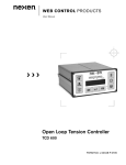
1. INTRODUCTION......................................................................................................................................................................3
2. USER INTERFACE...................................................................................................................................................................3
2.1. Keypad..................................................................................................................................................................................3
2.2. Idle Screen ............................................................................................................................................................................4
2.3. Login Screen.........................................................................................................................................................................4
2.4. Operating Modes ..................................................................................................................................................................4
2.5. User Hot Keys ......................................................................................................................................................................4
3. MENUS .......................................................................................................................................................................................5
3.1. Main Menu ...........................................................................................................................................................................5
3.2.Setup ......................................................................................................................................................................................5
3.2.1. Date Type......................................................................................................................................................................5
3.2.2. Date / Time ...................................................................................................................................................................5
3.2.3. Lock Setup ....................................................................................................................................................................6
3.2.4. Input Setup....................................................................................................................................................................6
3.2.5. Passwords .....................................................................................................................................................................6
3.2.6. Holidays........................................................................................................................................................................6
3.2.7. Edit Registers................................................................................................................................................................6
3.2.8. Local Setup ...................................................................................................................................................................7
3.3. Edit Keys Menu ....................................................................................................................................................................7
3.3.1. Add Key........................................................................................................................................................................7
3.3.2. Modifying key flags......................................................................................................................................................8
3.3.3. Add Password Key .......................................................................................................................................................8
3.3.4. Delete Key ....................................................................................................................................................................8
3.3.5. Modify Key...................................................................................................................................................................9
3.3.6. Edit Time Zone .............................................................................................................................................................9
3.3.7. Editing and Adding Access Levels...............................................................................................................................9
3.4. View Menu..........................................................................................................................................................................10
3.4.1. View Events................................................................................................................................................................10
3.4.2. View Key ....................................................................................................................................................................10
3.5. Print ....................................................................................................................................................................................10
3.5.1. Print Events.................................................................................................................................................................10
3.5.2. Print Keys ...................................................................................................................................................................10
3.5.3. Print Setup ..................................................................................................................................................................10
3.6. Maintenance........................................................................................................................................................................10
3.6.1. Upload ........................................................................................................................................................................10
3.6.2. Download....................................................................................................................................................................11
3.6.3. Clear APB...................................................................................................................................................................11
4. OPERATING MODES ............................................................................................................................................................11
4.1. Single Door with Two Readers ..........................................................................................................................................11
4.1.1. Single door, without Anti-passback............................................................................................................................11
4.1.2. Single door, with Anti-passback for entry only (Soft Anti-Passback)........................................................................11
4.1.3. Single door, with Anti-passback in both directions (Hard Anti-Passback) ................................................................11
4.2.Two Doors ...........................................................................................................................................................................11
4.2.1. Two doors without Anti-passback ..............................................................................................................................11
4.2.2. Two doors, with Anti-passback in both directions (Soft Anti-Passback) ...................................................................11
4.2.3. Two doors, with Anti-passback for entry only (Hard Anti-Passback)........................................................................11
4.2.4. Two doors, entry only Anti-passback .........................................................................................................................11
4.2.5. Soft Anti-Passback use loop with mode 8 as entry.....................................................................................................11
4.2.6. Elevator control ..........................................................................................................................................................11
5. ADVANCED FEATURES.......................................................................................................................................................11
5.1. Lock Setup..........................................................................................................................................................................12
5.1.1. RTE Input Polarity......................................................................................................................................................12
5.1.2. D.POS Input Polarity ..................................................................................................................................................12
5.1.3. D.POS Input Function ................................................................................................................................................12
DE6280U
1
5.1.4. Door Ajar Timeout .....................................................................................................................................................12
5.1.5. Door Lock Time Zone Functions................................................................................................................................12
5.2. Local Setup .........................................................................................................................................................................12
5.2.1. Flags Set #1 ................................................................................................................................................................12
5.2.2. Flags Set #2 ................................................................................................................................................................13
5.2.3. Flags Set #3 ................................................................................................................................................................13
5.2.4. Flags Set #4 ................................................................................................................................................................13
5.2.5. Flags Set #5 ................................................................................................................................................................13
5.2.6. More Parameters .........................................................................................................................................................14
5.3.Installation Status Screens ...................................................................................................................................................14
5.3.1. Inter-Controller Information Screen ...........................................................................................................................14
5.3.2. Multi Function Screen ................................................................................................................................................14
5.3.3. Who Am I? .................................................................................................................................................................14
6. REPLACEMENT PARTS LIST.............................................................................................................................................15
7. SPECIAL NOTES AND STATEMENTS ..............................................................................................................................15
7.1. Lithium Battery Handling / Disposal ...................................................................................................................................15
7.2. Compliance With Standards ...............................................................................................................................................15
2
DE6280U
1.INTRODUCTION
Thank you for choosing the Visonic Technologies AXS-100
proximity access control system. We are confident that this
product will serve your needs for years to come.
The Visonic Technologies AXS-100 is an electronic access
control system for controlling two doors. Eight controllers can be
networked together to control a total of 16 doors. The controller
relay activates a lock or an electromagnetic strike (EMS), when a
valid proximity key card or tag is presented to the reader located
outside the protected area.
Proximity tag
o r ca rd
The system can be connected to a serial printer for online and
offline printout of events.
The controller contains an alarm output relay, which trips when a
predefined alarm or trouble occurs.
The user can program a specific unlock time for each door.
The AXS-100 controller can also operate with a single door and
two readers to form an anti-passback configuration. The door lock
will not open again for the same key unless the reader read the
key on the other side of the door.
PC may be connected for use as supplementary monitoring only.
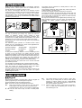
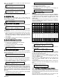
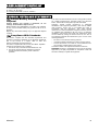
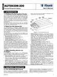
Each controller can govern one or two doors. The diagram below
illustrates the various possible combinations for a single
controller:
RF
Coded
RF
7
8
9
4
5
6
1
Yes
2
3
0
No
RDR-4 / RDK-4
Pro ximity reader
Esc
Enter
A XS-100
Con trol
U n it
Figure 1 - Access Control Functional Diagram
The use of proximity (non-contact) key makes the AXS-100
system an attractive access control solution in harsh
environments and in places with poor lighting conditions. The
proximity keys are totally sealed and wear resistant. The reader
reads the key ID, whenever the key is held close to the reader.
Most buildings have a few doors through which many individuals
enter and leave.
The AXS-100 system provides an excellent access control
solution at a very competitive price. Some of the applications for
which the AXS-100 is beneficial are:
Apartment buildings
Shopping Malls
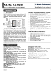
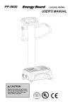
Single Door with Two Readers
Single Door
Office buildings
Municipal buildings
Kindergartens
Dormitories
Factories
Hospitals
Schools
In many of these buildings, there is a need for controlling access
to some or all of the doors. The system gives the security
department the ability to select where and when will a person be
allowed to go through a door. In case of loss or theft of a key, the
key may be easily barred from opening any of the locks, by
deleting it from memory. This precludes replacement of the
cylinder and associated keys as done in conventional doors.
The AXS-100 system can control from one to 16 door locks with
up to 5000 key records.
The controllers are networked using a simple twisted pair cable.
The controllers can be installed in different locations, close to the
locks. The system can produce various on-line and off-line
reports of key user lists and individual reader usage.
The system allows the user to restrict the validity of each key by
assigning each key with one or two time zones. The system
contains eight time zones.
Two Readers with Two Doors
Figure 2 - Door and Readers configurations
UL Compliance
The AXS-100XT is supplied with an external power supply and
was evaluated by UL. The AXS-100XT is a UL Listed controller.
All interconnecting devices must be UL Listed. The AXS-100
controller is supplied with an internal transformer and was not
evaluated by UL.
The following devices, which are described in this manual
were not evaluated by UL: RDK-4 keypad, RDR-4B reader,
IOX-4 input/output interface, printer and elevator control.
2.USER INTERFACE
2.1.Keypad
Each AXS-100 controller is equipped with a 4x4 key keypad. All
system programming is done through this keyboard.
The keypad buttons have the following functions:
Enter Execute a function (accept data and proceed)
Esc
Quit current function or menu and go one level back.
Pressing Esc a few times will return to the idle screen.
← , → Horizontal arrows used to move inside an edited field.
They are also used to skip a month in Holiday table
editing.
DE6280U
↑,↓
0–9
The vertical arrows are used to select a menu item,
select a day in Holiday table, as well as select special
functions in various screens (see par. "5.ADVANCED
FEATURES".) The down arrow signifies “forward”, and
the up arrow signifies “backward”.
Used for typing in numeric values while programming.
The “1” is also used for indicating Yes / On and “0” is
also indicating No / Off.
3
2.2.Idle Screen
2.4.Operating Modes
The AXS-100 idle screen is displayed as long as there is no user
intervention. The top line displays date and time.
2 7 /
0 1
0 8 : 3 1 : 1 7
While the idle screen is displayed and no events are displayed on
the bottom line, you may press certain buttons to get special
information from the controller or set a few functions (see
"2.5.User Hot Keys").
If date and time are not set, the screen will blink as shown:
- - /
- -
-
- : - - : -
-
The bottom line is used for displaying trouble and alarm
conditions:
2 7 / 0 1
0 8 : 3 1 : 1 7
F O R C E D
D O O R
1
Controller #1 will display its and the other controllers’ alarm and
trouble conditions. Controllers 2 through 8 will only display their
own events.
The controller memorizes the most recent 32-alarm/trouble
events. If no events are acknowledged and more than 32 events
are logged, the oldest events will be cleared.
To acknowledge an event, press the “0” or “1”. The oldest event
will be replaced by the next event in line (Pressing “0” will turn off
the buzzer. Pressing 1 will turn the buzzer on).
If no messages are displayed, the controller will sound a single
beep when “0” is pressed to indicate that the buzzer is disabled,
or a double beep if “1” is pressed to indicate that buzzer is
enabled.
2.3.Login Screen
In order to change system parameters and key records, or print
reports the user has to login. While display shows date and time:
•
Press Enter to reach the login screen.
•
Type the password followed by Enter.
P A S S WO R D
X X X X
If you entered an invalid password, the date and time screen will
re-appear.
The system recognizes two password levels:
Level #1 allows the user modify all system parameters including
passwords.
Level #2 allows the user to modify date and time and key records
(ADD, DELETE, MODIFY) only.
To be able to change passwords, you HAVE to log in with a level
#1 password.
Note: For initial password and resetting the passwords, refer to
the Installation Instruction. For setting passwords see sec.
“3.2.5.Passwords”.
The following are the AXS-100 operating modes:
Mode
2 doors, 2 readers, hard anti-passback
2
1 door, 2 readers
3
2 doors, 2 readers, soft anti-passback
4
1 door, 2 readers, soft anti-passback
5
Both EXIT in soft anti-passback mode
6
1 door, 2 readers, hard anti-passback
7
2 doors, 2 readers
8
Both ENTRY in hard anti-passback mode
9
Elevator control
1 door modes – connect lock to left side terminal block
2.5.User Hot Keys
You may press the following keys while the idle screen is
displayed and no events are displayed:
Key
Action
0
Acknowledges the displayed event message, one at a
time. Silences the buzzer.
1
Acknowledges the displayed event message, one at a
time. Activates the buzzer.
2
Toggles interface language if two languages are
loaded.
3
Not used
4
View reader status. If a “+” is displayed both readers,
the controller is OK. If one reader displays a “+” and
the other a “-“, then a hardware problem exists.
Pressing “4” again shows the total number of keys in
the database.
Pressing "5" shows the last tag code that was
presented to the external reader.
5
Not used
6
Shows firmware version.
7
Shows all the controllers in the loop (from 1 … 8). If a ““ appears instead of the controller number, a
communication problem exists. If a controller is
connected and is currently unavailable, its position will
change to ‘X’
8
Clears screen (usually used to clear the screen of
event messages.
9
Displays the address and operating mode (see
"2.4.Operating Modes”).
E N T E R
4
Description
1
DE6280U
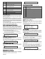
3.MENUS
The AXS-100 user interface is organized into a main menu and five sub-menus. The chart below shows all menu entries.
Main Menu
with password #1
with password #2
Setup
Date/Time
Edit Keys
View
Print
Maintenance
Date Type
Add Key
View Events
Print Events
Upload
Setup
Date/Time
Delete Key
View Keys
Print Keys
Download
Setup
Lock Setup
Modify Key
View
Timezones
Print Setup
Clear APB
Input Setup
with password #1
Time Zones
Passwords
Holidays
Access
Levels
Edit
Registers
Local Setup
A menu is a list of items to select from.
• Use the up and down arrows to scroll until reaching the
desired item.
• Press Enter to execute or Esc to cancel and go back.
• If you do not press any key for more than 90 seconds, the
controller will automatically log you out and revert to the idle
screen.
• Pressing the 0 key on any menu will toggle the menus
between text only and text plus selection number. In both
modes, you can reach a specific selection by pressing its
corresponding digit.
Example: LOCK SETUP can be reached from main menu by
pressing 1 for SETUP and then 3 for LOCK SETUP.
3.1.Main Menu
Once you login successfully, you will be presented with the main
menu. Depending on the password used to login, you will see
one of two main menus:
Main Menu screen, available with Password #1:
S E T U P
E D I T
K E Y S
Main Menu screen, available with Password #2:
Æ
D A T E / T I M E
E D I T
K E Y S
Press the down arrow twice to see the rest of the main menu.
Æ
V I E W
P R I N T
The following sections under chapter 3 explain all five sub-menus
in detail.
Æ
DE6280U
3.2.Setup
To enter the SETUP menu, log in with password #1.
The SETUP menu allows selecting one of six functions:
DATE TYPE
1. Select European /
American date format
DATE / TIME
2. Enter date and time
3. Set up locks’ open time in seconds LOCK SETUP
INPUT SETUP
4. Setup AUX Input /
Output on the IOX-4
PASSWORDS
5. Select passwords #1 and #2
HOLIDAYS
6. Set holidays
EDIT REDISTERS
7. Set / Edit system registers
LOCAL SETUP
8. Additional options
3.2.1.Date Type
The system can use the European (DD/MM/YY) or American
(MM/DD/YY) date format.
Select the appropriate date format and press Enter to set. The
screen will return to the SETUP menu.
ÆE U R O P E A N
A M E R I C A N
3.2.2.Date / Time
When entering the date and time setup screen, the date will be
displayed according to selected date format. Enter new date and
press Enter to move on to the time field. The time is always
shown in 24-hour format.
5
For example: If the date is September 17, 2002 and the time is
3:34 PM:
• Enter date: 170902 and press Enter.
• Enter time: 1534 and press Enter to save the new date and
time.
D A T E : 1 7 / 0 9 /
T I M E : 1 5 : 3 4
0 2
3.2.3.Lock Setup
Lock setup consists of specifying the unlock time in seconds (1 2000) for each lock. For example, for a door unlock duration of 5
seconds the value of 5 should be entered.
The detailed door unlock duration time process is as follows:
• Enter the lock number (1-16, or enter 99 to define all doors
unlock duration period at the same time).
• Press Enter.
• Enter the desired unlock time, according to the above
description. The display will show:
L O C K
# :
1
U N L O C K
T I M E : 5
If a “0” is entered for the unlock time, the lock works in toggle
mode. This means that when a key is presented to the reader,
the lock remains unlocked until a new key is presented to it.
3.2.4.Input Setup
Please refer to the IOX-4 Installation Instructions manual for more
details on this entry.
3.2.5.Passwords
Note: The password is a 4-digit number.
When entering this mode both passwords have to be set in order
to continue.
Modifying passwords should be handled with care. Only
password level #1 users can modify the passwords.
• Enter password #1 and press Enter
• Enter password #2 and press Enter
P A S S WO R D
P A S S WO R D
Print (via RS 232)
Each day of the year (366 days including leap years) can be
designated as a holiday. Each holiday should have a holiday type
(1, 2, 3, or 4) assigned to it.
H O L I D A Y S
1 . E D I T
2 . E R A S E
To change a holiday into a regular day, change its type to be 0.
When a certain date is displayed, press numeric keys 0, 1, 2, 3 or
4 for setting date type.
0 1 / 0 1
T Y P E :
Events log
Key records
Time zones
Events
Keys
Setup
6
0
3.2.6.2.Erase
The AXS-100 will prompt you to confirm before erasing the
holiday table. The “1” button is used as “YES” to confirm the
erasure. If you are sure you want to erase the table, press 1 and
then Enter.
E R A S E
A L L
H O L I D A Y S
( Y /
N ) N
3.2.7.Edit Registers
There are 128 data registers as follows:
Register Description
0
Entry/Exit Up/Down counter. Enables counting how
many entries minus exits occurred to enable counting
cars in a parking lot application, for example.
1
Capacity threshold for alarm relay operation. Can
indicate when a parking lot or other facility is full, for
example.
2
Entry counter (can be cleared by user from controller
or PC).
3
Left (bit 0) and right (bit 1) reader enabled (can be
controlled from PC). Most significant 12 bits MUST
be 1s to enable controlling the readers. This register
enables activating/de-activating each reader.
4, 5
From/To time in minutes during which lock 1 will
require two valid tags within 6 seconds to open. If
either register is greater than 1439 or if R4 is greater
or equal to R5, this feature is disabled.
6,7
From/To time in minutes during which lock 2 will
require two valid tags within 6 seconds to open. If
either register is greater than 1439 or if R6 is greater
or equal to R7, this feature is disabled.
8, 9
From/To time in minutes during which reader 1 will
switch from mode 0 to mode 1 (reserved for future
RDK-4 Tag+Pin or Tag only or for RDT-4 entry or
exit). IF either register is greater than 1439 or if R8 is
greater or equal to R9, this feature is disabled.
10, 11
From/To time in minutes during which reader 2 will
switch from mode 0 to mode 1 (reserved for future
RDK-4 Tag+Pin or Tag only or for RDT-4 entry or
exit).
If either register is greater than 1439 or if R10 is
greater or equal to R11, this feature is disabled.
12
Dial out event count threshold. Enables controllers
working as a modem to dial out to the central
computer download accumulated events.
3.2.6.Holidays
Each day of the year can be defined as a regular day or as one of
four holiday types. The holiday definitions are used in the Time
Zone Setup to grant access to certain key holders during
holidays. (Saturday and Sunday are not considered holidays
since they are part of the week day definition).
When entering the holiday setup screen, select one of two
choices:
1. EDIT - Change existing holiday schedule
2. ERASE - Delete holiday schedule
Press 1 for EDIT or 2 for ERASE.
F R I
Use the keypad to change the dates, as follows:
• Press right or left arrow to scroll months forward or
backwards.
• Press the DOWN or UP key to change the date by a single day.
• Press 5 to advance to the next programmed holiday.
• Press 7 to advance to January 1
• Press 8 to advance to July 1
• Press 9 to advance to December 31
# 1 : X X X X
# 2 : X X X X
Password #: 2 can do the following:
Modify
Date and Time
Add / delete / modify
Keys
View
3.2.6.1.Edit
DE6280U
C O N T R O L L E R
2
Register Description
13
For future use.
14, 15
Minute range (0 … 1439) during which Time and
Attendance is in Entry mode.
40-99
Events counting, expressed as pulses on any of the
inputs, in registers 40 to 99.
100
Alarm register. Exit delay in seconds.
101
Alarm register. Entry delay in seconds.
102
Number of alarm signals from an input in armed
mode before bypassing it
103
124
Select the controller address and press Enter.
3.2.8.5.Operation Mode
The AXS-100 system can operate in one of a few modes:
Mode
Description
1
2 doors, 2 readers, hard anti-passback
2
1 door, 2 readers
3
2 doors, 2 readers, soft anti-passback
Auto arm/disarm time zone selection
4
1 door, 2 readers, soft anti-passback
Main alarm arming register.
5
Both EXIT in soft anti-passback mode
125
Secondary alarm arming register.
6
1 door, 2 readers, hard anti-passback
127
Read ONLY entry counter.
7
2 doors, 2 readers
8
Both ENTRY in hard anti-passback mode
3.2.8.Local Setup
The Local Setup screen allow the user to set up the controller
address and operation mode as well as many other advanced
features of the controller.
The anti-passback feature is enabled when the controller
operates with a single door and two readers. The door lock will
not open again for the same key unless the reader reads the key
on the other side of the door. This prevents the user that entered
the protected area from passing the key to another person for
gaining access with the same key. This feature is implemented by
using an anti-passback timer.
In all LOCAL SETUP screens, pressing the up arrow button, will
open the SPECIAL SETUP screens. These screens will be
discussed in "5.ADVANCED FEATURES" bellow.
3.2.8.1. Anti-Passback Table Reset
When in any anti-passback mode, the AXS-100 uses a timer
table with a timer for each key. Whenever a key is presented and
accepted, its timer is set to number of half-hour interval as
defined in “3.2.8.2.Anti-Passback Duration” below. If the key is
not presented for more than the predefined interval, its timer will
be cleared and both readers will accept that key again. The user
has two other options for clearing all key timers at once without
waiting for each key timer to time out:
•
Select CLEAR APB in the MAINTENANCE menu.
•
Set an hour (0..23), at which time the anti-passback
table will be cleared automatically.
The APB CLEAR HOUR screen accepts a number between 0
and 23 or 99. Entering 99 will disable this feature.
A P B
R E S E T
9 9 : 0 0
H O U R
3.2.8.2.Anti-Passback Duration
The anti-passback duration is measured in half-hour increments.
Type in a number from 1 to 63.
The system initiates a key anti-passback to an interval of the
given number of half-hour intervals. A 24-hour anti-passback
interval is defined as 48. Press Enter to continue.
A P B
4 8
D U R A T I
O N
3.2.8.3.Alarm Relay Time
The alarm relay time is set up in seconds. Each alarm or trouble
event will cause the system to close the relay for this number of
seconds.
A L A R M
1 0
R E L A Y
T M
Enter number in range of 1 to 99 and press Enter to continue.
Please note that if the alarm relay is used for the “traffic light”
function, this screen is not important.
3.2.8.4.Controller Address
9
Elevator control
1 door modes – connect lock to left side terminal block
Use the “1” and “0” keys to set or reset each of the flags. The
flags and their functions are described below.
3.3.Edit Keys Menu
Note: All adding, deleting and editing of keys are performed
using the internal reader located on the LCD panel inside the
AXS-100 unit.
The Edit Keys menu allows you to add, delete, modify key
records as well as set time zones (available only if you logged in
with password level #1).
ÆA
D
M
T
A
D
E
O
I
C
D
L
D
M
C
K E Y
E T E
K
I F Y
K
E
Z O N
E S S
L
E
E
E
E
Y
Y
S
V E L
3.3.1.Add Key
When in ADD screen, the controller prompts you for adding a
key. Present a new key close to the key illustration on the panel.
The ADD screens will default to key data of the last added or
modified key. This feature facilitates quick addition of many keys
with same privileges.
S H O W
K E Y
A D D
Once the key is read, the controller will prompt for time zones to
assign to the key. You must assign at least one time zone for the
key to be usable (two different time zones can be assigned).
Enter a digit from 1 to 15 and press Enter.
The cursor will move to the second time zone. Enter a second
time zone number or press Enter to continue to next screen.
T I M E
T Z 1 :
Z O N E S
1
T Z 2 :
A D D
1
If “0” is entered for both TZ 1 and TZ 2, then the system will
operate in Access Level mode (see “3.3.7.Editing and Adding
Access Levels”).
Note: If Flag 7 in the FLAG SET 4 (see “5.2.4.Flags Set #4”) ON,
do not use time zone in key add. Use access level instead.
Each key can have an expiration date. The default is no
expiration date (00/00/00). If you would like to specify a date, type
it in the currently selected date format. Press Enter to continue.
V A L I D
U N T I L
A D D
0 0 / 0 0 / 0 0
The last screen is the valid door definition screen. The doors are
numbered 1 through 9 and A (for door 10) through G (for door 16).
The AXS-100 controller can be set to address #1 through #8.
Controller #1 is special in the sense that it concentrates
communications from other controllers for the PC.
DE6280U
7
If you choose to work in Access Level mode, then the following
screen will appear below (see “3.3.7.Editing and Adding Access
Levels”):
A C C E S S
L E V E L
A D D
1
Otherwise, the following screen will appear:
V A L I D
D O O R S
A D 1
- - - - - - - - - - - - - - - •
•
•
•
1 2 3 4 5 6 7 8 9 A B C D E F G
Use the arrows to move right or left to a specific door number.
Press “1” to permit, or “0” to deny access to a specific door
with this key.
If modifying the second group of valid doors, press DOWN
ARROW. The following screen appears:
V A L I D
D O O R S
A D 2
- - - - - - - - - - - - - - - -
change of parameters. Each additional key will receive the same
parameters as the key on which you pressed the UP arrow. This
mode allows quick adding of many keys with the same
parameters, without the need to press any additional buttons.
3.3.2.Modifying key flags
Seven flags are available for a key. Each flag activates or unactivates a specific function for that key.
Flag no.
1 2 3 4 5 6 7 8 9 A B C D E F G
Press Enter to continue. The system will store the new key
and display its serial number. Please note this number down
along with the name of the holder of this key.
K E Y
S A V E D
A S
N U M B E R
A D D
1 2 3
Note: It is recommended to keep a list of key-holder names and
keys serial numbers, in order to be able to delete stolen or lost
keys.
You may receive Error Messages in the following cases:
The key is already in database. It cannot be added again.
If the key is already added in the database, the display will be:
K E Y
A L R E A D Y
A D D
I N
D B
( 1 7 1 )
If there is no room for additional keys in the database, the display
will be:
N O
M O R E
S H O W
K E Y
A D D
Pressing the UP arrow BEFORE presenting a new key, will cause
the controller to display the following screen:
S E L E C T
A D D
K E Y
# :
0
This screen allows you to specify the starting memory location for
adding keys (a location other than the first available memory
address).
Example: Type in 1000 and press Enter. The controller will
check, starting at 1000, which location is free, will briefly display
that number and will return to the ADD screen waiting for a key.
Present a new key and set its parameters. Following the VALID
DOORS list, the controller will display that a key has been added
at location 1000 (assuming that this location was free).
If you add another key without logging out, the next key will be
stored in location 1001 unless that location is already used, in
which case the controller will look for the first free address higher
than 1001.
3.3.1.2.Skipping Data Entry and Repeating
Operation
8
Z O N E S
A D D
1
T Z 2 :
1
is pressing the UP arrow while in the VALID
This will cause the AXS-100 to accept the
prompt for more keys without allowing the
2
Doubles the time that a door remains open after the
key is presented. The target population are the
handicapped or others that might have difficulty
accessing the door.
3
Someone with this key cannot open the door unless
another valid key is presented immediately afterward.
4
Does not enable opening any door in the system.
5
This is the Master Tag function and has special
privileges.
6
Arms/disarms the alarm system when the key is
presented.
7
Fire off IOX-4 relay #25 when tag is presented.
Z O N E S
1
T Z 2 :
A D D
1
Press the DOWN ARROW. Each number refers to an available
flag.
Using the cursor, scroll through flags, pressing 1 to activate or 0
to de-active
K E Y
F L A G S
- - - - - - -
A D D
1 2 3 4 5 6 7
3.3.3.Add Password Key
Note: Adding password key to use with RDK-4 v3.00 only (see
user manual RDK-4).
To add a password key to the database, you need to enter a
number (1-10 digits) in the Add Key screen.
S H O W
•
K E Y
A D D
Press Enter and continue according to par. “3.3.1.Add Key”.
3.3.4.Delete Key
To delete a key from the database, you either need the key itself
or its serial number as displayed by the system when you added
the key. The controller prompts you for either one of the two
options:
• If you possess the key to be deleted, simply present it to the
built-in reader on the panel.
• If the key was lost or stolen you should enter its serial number.
This number should be taken from the user list prepared when
adding keys (see “3.3.1.Add Key”).
S H O W
K E Y
D E L
O R
T Y P E # :
When you start typing the first digit of the serial number, the
screen will display:
Once the key is read, the controller will prompt for time zones to
assign to the key.
T I M E
T Z 1 :
A second option
DOORS screen.
current key and
Overrides the anti-passback function, i.e., lets the
user access the door without regard to anti-passback.
T I M E
T Z 1 :
R O O M
Once in ADD screen, the controller will prompt you for a key to be
added.
1
These flags are set as follows: Enter the ADD key function and
present a new key. The following display appears:
A D D
3.3.1.1.Setting the Start Key Location
Flag Characteristics
K E Y
•
•
# :
X X X X
Enter the number
Press Enter to delete.
DE6280U
Once you press Enter, the controller will delete the key and
display the message:
K E Y
1 1 1
D E L
D E L E T E D
- - •
•
You may receive the following Error Message:
• Key is not in database, so it cannot be deleted.
U N K N O WN
K E Y
Note: If code “999” is entered and dip switches 7 and 8 are ON,
then the entire database will be erased from the whole loop
3.3.5.Modify Key
The MODIFY KEY screens allow you to modify existing key
record settings. You may either present the key or type its
number followed by Enter.
S H O W
K E Y
O R
T Y P E # :
M O D
3.3.5.1.Modify Time Zones
If you present a key, the display will show its number for a few
seconds.
T I M E
Z O N E S
M O D
T Z 1 :
X
T Z 2 :
X
Then, the time zones screen will appear. You may type Enter
immediately to confirm the current time zone setting OR change
the time zone:
• Select one or two time zones by typing a number from 1 to 64.
Note: If selecting only one time zone, TZ1 and TZ2 should
have the same number. If selecting two time zones, TZ1 and
TZ2 should have different numbers, appropriate to the time
zone number.
• Press Enter to move to TZ2 and enter the appropriate time
zone number. Press Enter.
3.3.5.2.Modify Expiration Date
Each key has an associated expiration date.
• For a key with no expiration date enter 00/00/00
To change the expiration date:
• Enter a new expiration date and press Enter
• Press Enter to continue
V A L I
1 1 /
D
U N T I
0 2 / 0 3
L
M O D
3.3.5.3.Modify Valid Door
The last screen in this sequence is the valid door definition
screen. The doors are numbered 1 through 9 and A (for door 10)
through G (for door 16).
V A L I D
D O O R S
M O 1
- - - - - - - - - - - - - - - 1 2 3 4 5 6 7 8 9 A B C D E F G
Use the arrows to move right or left to a specific door number.
Enter “1” to permit, or “0” to deny a specific door with this key.
Press ARROW DOWN to return to Valid Doors mod 2. If
ARROW UP is pressed the following screen appears:
S E L E C T
X
L A S T
K E Y : 0
In the above screen, “x” in the SELECT field signifies the current
key that was modified (the actual number will be displayed).
Instead of “0” in the LAST KEY field, if a key number from 1 to
5,000 is entered, the previously performed modifications will
apply to the sequence of keys from the current key (which was
just modified) to the key number that was designated in the LAST
KEY field.
• If modifying the second group of valid doors, press DOWN
ARROW. The following screen appears:
•
•
•
V A L I
DE6280U
D
D O O R S
M O 2
- - - - - -
- - - - - -
-
1 2 3 4 5 6 7 8 9 A B C D E F G
Perform the above procedure.
Press Enter to finish the modify procedure.
The system will store the modified key and display the
following message:
K E Y
X X X
M O D
M O D I F I E D
3.3.6.Edit Time Zone
The AXS-100 system recognizes up to 64 time-zone templates.
The templates are assigned to user keys to facilitate the definition
of different time and day privileges for different keys. Each
template defines two from/to times, weekdays and up to four
holiday types.
Each key database record can be linked to one or two templates.
Using two templates allows definition of split shifts or “graveyard”
shifts (through midnight).
Time From To From To
M
Zone hour hour hour hour
X
T W
T
F
X
X
1
08:00 11:00 08:00 11:00
X
X
2
09:00 19:30 09:00 19:30
X
X
3
07:15 18:00 07:15 18:00
X
X
4
09:00 17:30 09:00 17:30
5
08:00 11:00 08:00 11:00
6
7
X
X
09:00 19:30 09:00 19:30
X
X
07:15 18:00 07:15 18:00
X
X
S
H H H H
1 2 3 4
X
X
X
X
X
X
S
X
X
X
X
X
X
X
X
X
X
.
.
.
.
.
.
.
.
.
.
.
.
. . . .
.
.
.
.
.
.
.
.
.
.
.
.
. . . .
.
.
.
.
.
.
.
.
.
.
.
.
. . . .
62 09:00 19:30 09:00 19:30
X
X
63 07:15 18:00 07:15 18:00
X
X
X
X
64 00:00 23:59 00:00 23:59
X
X
X
X
X
X
X
X
X X X X
The first TIME ZONE screen prompts for a template number.
Press a digit from 1 to 64 (e.g., 2) followed by Enter.
T I M E Z O N E
S E L E C T
# : 2
The next screen lets you set the first FROM /TO time period in
hours and minutes.
F R O M
1 0 9 : 0 0
T O
1 9 : 3 0
The FROM time has to be earlier than the TO time. An exception
is when both FROM and TO times are set to 00:00, which sets
the time zone from 00:00 to 23:59.
Enter the FROM time followed by Enter and then the TO time.
Press UP ARROW to go to the second FROM/TO period, OR
simply press Enter to skip.
The last screen in TIME ZONE SETUP lets you define days of
week and special holidays valid for this template (see
“3.2.6.Holidays ”).
Use the left and right arrow keys together with key 1 and key 0 to
determine which days and which holidays are valid for this time
zone.
Press Enter to store the time zone.
D O W
M T WT F S S 1 2 3 4
3.3.7.Editing and Adding Access Levels
When setting Access Levels from the controller, a maximum of
128 Access Levels are available. For each Access Level, up to 4
Time Zones can be used (of up to 64). Each Time Zone can have
up to 16 valid doors.
Enter the Edit Keys menu (available only if you logged in with
password level #1) and scroll down to Access Levels.
9
•
•
•
•
•
•
Press Enter. The following screen appears:
S E L E C T
A C C E S S
L E V E L
1
Enter a number from 1 to 128. Press Enter. If adding a new
Access Level, fill in the new number, and define the time zone
and valid doors. The following screen appears:
T I M E
Z O N E
1
1
Enter the number of the time zone (from 1 to 64).
Press Enter. The following screen appears:
V A L I D
D O O R S
1 2 3 4 5 6 7 8 9 A B C D E F G
Scroll using the cursor and select the valid doors.
Press Enter to move to the next time Zone. Set up to four
time zones using the above procedure. To stop before
entering four time zones, select time zone 0 and press Enter.
3.4.View Menu
The VIEW menu provides three item selections:
• View events stored in the controller
• View key record
• View time zone record
ÆV I E W
E V E N T S
V I E W
K E Y S
V I E W
T I M E Z O N E
The VIEW screens do NOT allow modifying any data, only
viewing it.
Use the UP and DOWN arrows to point to the desired item and
press Enter.
3.4.1.View Events
The VIEW EVENT screen lets you view the events logged into
the controller in reverse chronological order - the latest events
are viewed first. Each event record is displayed on two screens.
The event type and date/time are displayed on the first screen.
Press Enter to view the second screen
e v t
t y p e
2 0 / 0 3 / 9 8
0 3 : 5 1
The second screen shows the origin of the event, such as door 1
or 2. If the event involves a valid or an invalid key, the second line
will display “ID ###”. In case of a valid key, the number will be the
key index number assigned by the system when that key was
added. If the key is invalid, the system will display the unique
code embedded in the key, permitting you to find out if someone
is trying to open several doors with the same key. Press Enter to
view next event.
S O U R C E
I D
1
X X X X
You may press the Esc button at any time to return to the menu.
3.4.2.View Key
The VIEW KEY screens are exactly the same screens as in
MODIFY KEY but without being able to modify the data. Please
refer to MODIFY KEY (see “3.3.5.Modify Key”). Description for
operating instructions.
S H O W
K E Y
O R
T Y P E # :
3.5.Print
The PRINT menu lets you send the event list, the key list or the
system setup to a serial printer connected to the RS-232 port of
the AXS-100 controller. Use the Up/Down arrows to point to the
desired report and press Enter. For example:
P R I
P R I
10
N T
N T
3.5.1.Print Events
The PRINT EVENTS screen will prompt you for the number of the
controller you wish to get the printout from. Enter the controller
number (1-8) and press Enter.
P R I N T
E V E N T S
C O N T R O L L E R
1
The display will show an event counter, counting up to 1000 events.
P R I N T
E V E N T S
E V E N T # :
X X X
You may press the Esc button at any time to stop printing. Even
after pressing the Esc button up to 32 lines may be printed before
stopping. AXS-100 event printout sample:
LN# DATE
221 18/09/02
222 18/09/02
TIME EVT TYPE
DOOR/CONT. ID
11:20 VALID KEY
4
544
11:19 INVALID KEY
2
59245
3.5.2.Print Keys
Selecting PRINT KEY function will immediately print keys
information. Each key added to the AXS-100 will have a line
printed with all its data including the key number, time zones,
expiration date and valid doors.
The display will show the index number of the key being printed.
You may press the Esc button at any time to stop printing. After
pressing the Esc button, up to 32 lines may be printed before
stopping.
P R I N T
K E Y S
K E Y # :
X X X
AXS-100 key information printout sample:
K.ID
101
102
TO DATE
00/00/00
31/12/02
TZ1
1
1
TZ2
2
1
VALID DOORS
1234---89------1-3-5-----------
3.5.3.Print Setup
Selecting the PRINT SETUP option prints out a time zones and
holiday report.
Each Time Zone has a line printed in the following format:
Zone #1 From hour To hour
Days of week and holidays
1
06:00
22:00
M-WTFS-12Each holiday will be printed with day/month and holiday type:
Day/Month
Holiday Type
01/11
2
22/12
1
3.6.Maintenance
The Maintenance menu allows you to upload complete setup and
key database to PC, download complete setup and keys to other
controllers in the network and clear the anti-passback counters
for ALL the 5000 keys.
3.6.1.Upload
The UPLOAD screen allows you to save a complete setup file to
a computer connected to a AXS-100 controller #1 via a simple
RS-232 cable (connection diagram can be found on the inside of
the controller door.)
You can use any terminal software under Windows to log all text
sent from AXS-100 controller into a file of your choice.
Selecting the UPLOAD screen from the MAINTENANCE menu
will cause the controller to send all key records and setup records
to the computer.
The last line will have a double semi-colon (;;).
Notes: Pressing Esc while uploading will cause the upload to
abort.
ONLY controller #1 can send the setup to a computer.
E V E N T S
K E Y S
DE6280U
3.6.2.Download
3.6.3.Clear APB
The DOWNLOAD screen allows you to send complete setup and
key database from controller #1 to ALL other controllers in the
network.
Log in and enter MAINTENANCE menu.
Scroll down to DOWNLOAD and press Enter.
Wait until screen goes back to MAINTENANCE menu.
The CLEAR APB screen allows you to reset all anti-passback key
counters. When a key is presented to a reader whose controller is
configured for anti-passback, it sets off an anti-passback period
defined in half-hours in MISC SETUP.
Clearing the counter table with CLEAR APB, will cause the
controller to accept ALL keys again from any of the readers.
Please note that the counter table can also be cleared
automatically one time every day by setting the APB RESET
HOUR in LOCAL SETUP to a number in range of 0 (midnight)
through 23 (11pm at night).
D O WN L O A D
S E T U P
4.OPERATING MODES
The AXS-100 controller network can function in a loop wide antipassback mode:
This mode causes controllers #1 through #8 to share tag entry
and exit events. To achieve this, you need to set each controller
to any of the anti-passback modes detailed below and set flag 8
in FLAGS SET #2 screen (see sec. 3.2.8.2.Anti-Passback
Duration). This operation is specific to each controller and is NOT
transmitted to all controllers.
For hard anti-passback, an exit must follow each entry (for reentry to occur). An entry must follow an exit (for re-exit to occur).
For soft anti-passback, an exit must follow each entry (for re-entry
to occur), but unlimited exit may occur several times without reentry.
4.1.Single Door with Two Readers
There are three modes dealing with a single door and two readers.
In these modes, the door number is the odd number for this
controller, i.e. door #1 for controller #1, door #3 for controller #2.
Note: The Magnetic Lock (Maglock) or Electro-Magnetic Door
Strike (EMS) has to be connected to left side door connector!
The three modes are:
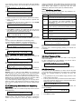
4.1.1.Single door, without Anti-passback
The two readers control a single door, one within and the other,
outside of the secured area. This is mode 2.
ENTER
ENTER PASSWORD
XXXX
>SETUP
ENTER Enter
EDIT KEYS
ENTER
ENTER
ENTER
EDIT REGISTERS
>LOCAL SETUP
ENTER
ENTER
Any exit has to be preceded by an entry. Every entry has to be
preceded by an exit. This is mode 6.
4.2.Two Doors
The “Two Doors” mode is the most common operating mode, in
which two doors’ locks are controlled by each controller. Each of
the two doors is controlled separately. Controller #1 controls
doors #1 and #2, controller #2 controls doors #3 and #4, etc.
4.2.1.Two doors without Anti-passback
This mode allows the connection of two separate doors or gates
without the anti-passback feature. There is no interaction
between the two locks. This is mode 7 and is the factory default.
4.2.2.Two doors, with Anti-passback in both
directions (Soft Anti-Passback)
This mode allows the connection of two separate doors or gates
with the anti-passback feature. Lock #1 (left side) is used for entry
and lock #2 (right side) is considered as the exit. This is mode 3.
4.2.3.Two doors, with Anti-passback for
entry only (Hard Anti-Passback)
This mode allows the connection of two separate doors or gates
with the anti-passback feature. Any exit has to be preceded by an
entry. Every entry has to be preceded by an exit. This is mode 1.
4.2.4.Two doors, entry only Anti-passback
Default is 2975
>DATE TYPE
DATE/TIME
4.1.3.Single door, with Anti-passback in both
directions (Hard Anti-Passback)
MODE
7
ENTER
ENTER
APB RESET HOUR
99:00
EDIT REGISTERS
>LOCAL SETUP
Mode is from 1 to 9
(9 represents
elevator control)
4.1.2.Single door, with Anti-passback for
entry only (Soft Anti-Passback)
Multiple exits are allowed, but only a single entry is allowed until
the key is presented to the inside reader. This is mode 4.
The two doors are for entry only. The Anti-passback will work with
the other controller [controllers #1 to #8] on the loop that is set to
mode 5. This is mode 8.
4.2.5.Soft Anti-Passback use loop with mode
8 as entry
The two doors are for exit only.
This is mode 5.
Note: 4.2.4 and 4.2.5 can operate together as entry and exit, and
together with all other modes within a loop.
4.2.6.Elevator control
Elevator control using IOX-4 add-on cards. This is mode 9.
For full description, refer to the IOX-4 user manual.
5.ADVANCED FEATURES
The AXS-100 user interface allows for advanced features and
also lets the user make shortcuts in certain situations for
speeding up data entry. All hidden features are accessed by
pressing the UP ↑ and DOWN ↓ arrow buttons. The UP ↑ arrow,
where available, lets you reach data entry screens for extra
features. The DOWN arrow, where available, acts like the Enter
button (execute function) but executes the same function again.
DE6280U
This allows for fast adding or modifying of keys. The following
sections list the extra functions available using the UP and
DOWN arrow buttons modification of many keys without the need
to press any button.
11
5.1.Lock Setup
While the cursor is on unlock time in the LOCK SETUP screen
(bottom line), you may press the UP arrow to access the
advanced lock features.
The advanced features are:
• RTE input Polarity - Normally Open/Normally Closed.
• D.POS input Polarity - Normally Open/Normally Closed
• D.POS input function.
• Door Ajar timeout
While in Extended Lock Setup screens, pressing the Esc button
will void the changes and will cause the Lock Setup screen to
reappear.
5.1.1.RTE Input Polarity
The RTE (Request-To-Exit) default input is set to N.O. (Normally
Open), as the standard triggering device may be a Normally
Open push button. If your triggering device has a Normally
Closed output (such as a PIR detector) you need to change the
AXS-100 input to N.C. (Normally Closed) as described:
• Press the ‘1’ button to define NC input
• Press Enter to continue
R T E
P O L A R I T Y
D P O S
P O L A R I T Y
N O
N C
5.1.2.D.POS Input Polarity
The D.POS (Position) input default is set to N.C. (Normally
Closed). If you need to change the input to be N.O. (Normally
Open), press the ‘1’ button. Press Enter to continue.
5.1.3.D.POS Input Function
The D.POS input has two possible uses:
Door position switch - 0
Reader enable switch - 1 when there a need to disable the
reader (prevent entrance) until the D.POS input is activated. The
option of reader enable is commonly used in parking lot gates
where the reader is activated only when an under-pavement
sensor detects an approaching car.
Select mode and press Enter to continue.
Function 5: Prevent entry and exit - Do not open lock for any
tag which is not a master tag. Exit is NOT allowed.
T I M E
Z O N E
T Z
F U N C T I O N
To select the time zone in which this lock will automatically be
unlocked type in a number between 1 and 15 or 0 to disable the
time zone feature. Press Enter.
Type in a number between 1 and 5 corresponding to functions
above. Press Enter to save and return to unlock duration screen.
Note: When unlock time is set to "0" (toggle mode), do not
operate the Time Zone Function at the same time.
5.2.Local Setup
While in any of the Local Setup screens, you may press the up
arrow to enter extra setup screens. These contain many more
functions for finer tuning of the controller, mainly for special
situations.
There are 17 screens divided to three groups:
• Flags Setup - 5 screens.
• Numeric values in range of 0 to 255 – 8 screens.
• Numeric values in range of 0 to 65535 – 4 screens.
To advance to next screen press Enter.
Once you modify the required parameter, you may press the
down arrow to return to the regular Local Setup screens. Press
Enter until you return to SETUP menu to save changes.
Pressing Esc before returning to setup menu, will void any
changes to the flags.
5.2.1.Flags Set #1
Flag Function
Invalid Key Alarm flag. If this flag is set, any
invalid key will cause the AXS-100 to display an
invalid key message and turn on the alarm relay.
OFF
2
Display PIN code after adding key tag. This
feature should be turned on if an RDK-4
(proximity reader with keypad) is connected to the
controller. Following display of key number, the 4digit PIN code will display for a few seconds. This
flag will also cause VIEW KEYS to display the
PIN code.
OFF
3
For future use
OFF
4
Enable buzzer on alarm/trouble. This flag can
also be set by pressing the “1” or “0” keys in idle
screen. If the buzzer is enabled and there is at
least one unacknowledged event, the buzzer will
sound every 4 seconds.
OFF
5
If ON, enables viewing the key code in addition to
other key parameters.
OFF
6
Open lock for half time when working with backup
battery to save battery power. Setting this flag will
cause the controller to shorten open time when
working off a backup battery.
OFF
7
Alarm relay control:
1->alarm/trouble, 0->computer control.
THIS FLAG SHOULD BE “1”, unless the relay
control is from the computer.
ON
8
Door relay control:
1->direct control,0->computer control.
THIS FLAG SHOULD BE “1”, unless the relay
control is from the computer.
ON
5.1.5.Door Lock Time Zone Functions
Locks can have a time zone associated with them for operating
with special functions.
The following functions are available:
Function 1: Auto Open - The lock will unlock automatically
whenever the time zone is valid.
Function 2: First Valid Tag - The lock will unlock and stay
unlocked for the duration of the time zone (if currently valid) upon
presentation of the first valid tag.
Function 3: Ignore Door Ajar - This feature is applicable only if
RDR-4B readers are used. The RDR-4B is similar to the RDR-4
with two additional wires that activate a local buzzer when the
door ajar is detected. If mode #3 is selected and current day and
time is within the selected time zone, the RDR-4B buzzer output
will NOT sound.
Function 4: Prevent entry - Do not open lock for any tag which
is not a master tag. Exit is allowed.
Default
1
5.1.4.Door Ajar Timeout
The Door Ajar default timeout is 20 seconds. In this screen you
may change it from 20 to 90 seconds in 10-second increments.
Press button ‘2’ to ‘9’ followed by Enter to continue.
0
0
Once all flags are set, press Enter to continue.
12
DE6280U
5.2.2.Flags Set #2
When in SETUP screen, select LOCAL SETUP.
Once in LOCAL SETUP, press UP arrow Æ Enter.
The display will show:
S E T U P
F L A G S
2
1 2 3 4 5 6 7 8
Use the “1” and “0” keys to set or reset each of the flags. The
flags and their functions are described below:
Flag Function
Flag
4
5
Function
Default
If set, controller will demand a valid password OFF
from the PC before allowing it to send
commands.
The password will enable up to 500 commands
with inter-command timeout of 5 minutes.
Reserved - Not in use
OFF
7
Enable [ON], disable [OFF] the broadcast of all
setup messages from the PC to controllers #2 #8.
Enable [ON] disable [OFF] key-press buzzer.
8
For future use.
6
Default
ON
The controller will attempt to dial out using a
modem when the new event count has exceeded
the number in data register [12].
OFF
MODEM - Auto answer after 1 ring. If an external
modem is connected to the AXS-100 RS-232
terminal, the modem will be initialized to answer
after one ring after power up and every time a
message fails to be acknowledged by the PC.
OFF
3
The controller will attempt to dial out using a
modem when an alarm is detected in any
controller.
OFF
4
Send Event messages in text mode. If flag is
cleared, the controller will send messages in
numeric mode.
OFF
S E T U P
F L A G S
4
1 2 3 4 5 6 7 8
Use the “1” and “0” keys to set or reset each of the flags. The
flags and their functions are described below:
5
Fire up IOX-4 relays 26 to 32 depending on event
type. Relay 26 - Valid key indication.
Relay 27 - Unknown key indication.
Relay 28 - Alarm conditions.
Relay 29 - Trouble conditions.
Relay 30 - Long read indication.
Relay 31 - Arm/disarm alarm system.
Relay 32 - Valid key failed to open.
For further information, refer to the IOX-4 manual.
OFF
Flag Function
6
Decrement anti-passback counters.
ON
7
Controller #1 - Capture alarm/trouble events from
other controllers. If cleared, controller #1 will NOT
display and close alarm relay upon receipt of
alarm/trouble indication from other controllers.
ON
Controllers #2 - #8 - Anti-passback is loop-wide.
Controllers #2 to #8 can share entry/exit
information between themselves to allow for loop
wide anti-passback operation.
ON
1
2
8
5.2.3.Flags Set #3
When in SETUP screen, select LOCAL SETUP.
From LOCAL SETUP, press UP arrow Æ Enter Æ Enter.
The display will show:
S E T U P
F L A G S
3
1 2 3 4 5 6 7 8
Use the “1” (ON) and “0” (OFF) keys to set or reset each flag.
The flags and their functions are described below:
Flag
1
2
3
Function
Default
For controlling the buzzer of the RDR-4B while a OFF
green or red color is displayed.
ON-Buzzer sounds when valid or invalid key
presented.
OFF-Buzzer sounds only if forced door or door
ajar events.
Report Valid key/Valid exit only if the door is OFF
open.
Interlock feature. Single lock will open at any OFF
given time for both reader and RTE.
DE6280U
ON
5.2.4.Flags Set #4
When in SETUP screen, select LOCAL SETUP.
From LOCAL SETUP, press the UP \arrow Æ EnterÆ EnterÆ
Enter.
The display will show:
Default
1
Alarm functionality using IOX-4 boards
OFF
2
Global arm/disarm of alarm system
OFF
3
Ignore RTE input
OFF
4
Report write operation to flash EEPROM.
OFF
5
Print paper slip if VALID KEY in controller #2 to #8.
OFF
6
Alarm relay is used with register 0 as up/down
counter
OFF
7
Do not use time zones in key add/modify. Use
access level instead.
OFF
8
Enable the use of Prevent Entry bitmap table
OFF
5.2.5.Flags Set #5
When in SETUP screen, select LOCAL SETUP.
Once in LOCAL SETUP, press UP arrow Æ Enter .
The display will show:
S E T U P
F L A G S
5
1 2 3 4 5 6 7 8
Use the “1” and “0” keys to set or reset each of the flags. The
flags and their functions are described in the following table:
Flag Function
Default
1
Enable IOX-4 board 1
OFF
2
Enable IOX-4 board 2
OFF
3
Enable IOX-4 board 3
OFF
4
Enable IOX-4 board 4
OFF
5
If ON, door becomes released and locks again
only after entry (for emergency situations such as
fire, etc.).
OFF
6
Motorized bolt door lock functionality for locks
with unlock time of zero seconds.
OFF
7
Use tamper input to relock both doors locks.
OFF
8
Reset controller if any reader is
communicating for more than 3 minutes.
not
ON
13
5.2.6.More Parameters
5.3.Installation Status Screens
The default value for these screens is 255. Simply press Enter to
continue.
Easily accessible screens are available for your use in order to
monitor the installation status and quality.
Name
5.3.1.Inter-Controller Information Screen
Reader
timeout
Network
retry
RDR
Toggle /
Scan
Door
position
Elev.
Relay TM
Printer
pacing
PC ack.
Timeout
Bold
relock time
Reserved
Door ajar
timeout
Function
Value
Range
Reader communication failure timeout. 8..100
Default when 255, is 24 cycles of approx.
150mS = 3 seconds. Increasing the
number in very noisy environments will
prevent frequent failure messages.
Network message transmission retries. 1..255
Default when 255, is 7. Increasing the
number in very noisy environments will
prevent frequent failure messages.
This is a dual purpose value:
0..31
Reader Loop Delay is the time delay
between full scans of all the readers in the
system. The delay is defined in 10mS
increments.
Toggle Readers activates the reader
toggle mode in which the readers
alternately transmit to allow installation in
close proximity situations.
Example:
1. To define a reader loop delay of
50ms without reader toggling, the
value should be 5 (=50/10).
2. To define reader toggling without
reader loop delay, the value
should be 16.
3. To define a reader loop delay of
50mS with reader toggling, the
value should be 21 (=50/10 + 16).
Door position debounce time in 10mS 1..255
increments. Default when 255, is 300mS.
The time period between presenting the 1..255
tag to the reader and pressing the desired
floor number.
The elevator will not respond to pressing
the floor number after this time period.
Printer line pacing in 100ms increments.
1..250
Default when 255, is 100mS.
Time for the controller to wait to a PC 1..255
ACK ( x 10 ms)
The period of time that passes from 1..255
whenever the door is closed until it locks.
For future use.
Defines the door-ajar timeout for both 0..65535
doors. Changing Door ajar timeout will
override the timeout defined in LOCK
SETUP. You may select a separate doorajar timeout per door in 10-second
increments from 20 to 90, or select a
common door ajar timeout in 1-second
increments by modifying this parameter
from 65535 (default) to the number of
seconds required. This field is accessible
by executing the following sequence
System Number
0..65535
For future use.
0..65535
System #:
PC
password
Load
In the PC password mode press UP arrow
setup
in order that load setup default
defaults
Y/N
While in idle screen (date and time on top line, bottom line blank)
press 7 on controller #1. The display will show:
1 8 / 0 9 / 0 2
1 7 : 1 0
C T R L R S :
1 2 - - - - The bottom line lists the controllers connected to controller #1. If
a controller has been detected and is currently unavailable, its
position will change to “X”.
Press 5 to view communication quality with each controller.
1 9 / 0 6 / 0 0
1 7 : 1 0
C T R L R S :
T S - - - - The screen will change to show a letter “A” through “T” for each
controller that answers. The letter “T” denotes perfect
communication with the controller in question, while “A” is a very
bad communication with same controller. Press Enter to exit to
idle mode.
5.3.2.Multi Function Screen
This screen allows viewing reader communication failures,
number of tags and network collisions.
Press 4 from idle screen.
R D R 1
E R :
+ 1 1 7 8
R D R 2
E R :
+ 4 7 2 7
If a reader is connected and the cable is intact, the number
should have a plus sign and stable (increase by 1 every few
seconds is fine). If the number increases by 8 every second,
there is almost no successful communication messages with the
reader, and the cables must be checked.
You can clear the counters by pressing the “0” button.
A minus sign in front of the number indicates no communication
with the reader.
Press Enter to change the display to the following:
K E Y S :
6 4
C O L L I S I O N S :
0
This screen details how many keys are programmed into the
controllers and whether or not any communication collisions were
detected.
Press Enter to return to idle screen.
5.3.3.Who Am I?
Press “9” at idle screen:
1 8 / 0 9 / 0 2
1 7 : 1 0
A D D R :
0 1
M O D E :
7
This screen shows the controller address (see "3.2.8.4.Controller
Address”) and mode of operation.
The different modes of operation are:
Mode
1
2
Anti-passback
Entry only
2
1
No Anti-passback
3
2
Entry and Exit
4
1
Entry Only
5
2
Exit Only
6
1
Entry and Exit
7
2
No Anti-passback **
8
2
Entry Only
9
Locks
Elevator control
** Default
14
DE6280U
6.REPLACEMENT PARTS LIST
1. Lithium battery 3V, cat. No. 0-9913-0.
2. CDR-1, cat. No. 9923.
3. Proximity reader RDR-4, cat. No. 3-6304-0
7.SPECIAL NOTES AND STATEMENTS
7.1.Lithium Battery Handling /
Disposal
Caution: Battery may explode if mistreated, do not
recharge, disassemble or dispose in fire.
Replace battery with PANASONIC Coin battery type CR2032,
3V only. Use of another battery may present a risk of fire or
explosion.
Dispose any used Lithium battery only in an approved disposal
container.
7.2.Compliance With Standards
This device complies with the essential requirements and
provisions of Directive 1999/5/EC of the European Parliament
and of the Council of 9 March 1999 on radio and
telecommunications terminal equipment.
This device complies with Part 15 of the FCC Rules. Operation
is subject to the following two conditions:
1. This device may not cause harmful interference, and
2. This device must accept any interference received,
including interference that may cause undesired
operation.
DE6280U
This device has been tested and found to comply with the limits
for a Class B digital device, pursuant to Part 15 of the FCC
Rules. These limits are designed to provide reasonable
protection against harmful interference in residential
installations. This equipment generates, uses and can radiate
radio frequency energy and, if not installed and used in
accordance with the instructions, may cause harmful
interference to radio and television reception. However, there is
no guarantee that interference will not occur in a particular
installation. If this device does cause such interference, which
can be verified by turning the device off and on, the user is
encouraged to eliminate the interference by one or more of the
following measures:
– Re-orient or re-locate the receiving antenna.
– Increase the distance between the device and the receiver.
– Connect the device to an outlet on a circuit different from
the one which supplies power to the receiver.
Consult the dealer or an experienced radio/TV technician.
WARNING! Changes or modifications to this unit not expressly
approved by the party responsible for compliance could void
the user's authority to operate the equipment
15
WARRANTY
Visonic Technologies ("the Manufacturer") warrants its products hereinafter referred to as
"the Product" or "Products" to be in conformance with its own plans and specifications
and to be free of defects in materials and workmanship under normal use and service for
a period of twelve months from the date of shipment by the Manufacturer. The
Manufacturer's obligations shall be limited within the warranty period, at its option, to
repair or replace the product or any part thereof. The Manufacturer shall not be
responsible for dismantling and/or reinstallation charges. To exercise the warranty the
product must be returned to the Manufacturer freight prepaid and insured.
This warranty does not apply in the following cases: improper installation, misuse,
failure to follow installation and operating instructions, alteration, abuse, accident or
tampering, and repair by anyone other than the Manufacturer.
This warranty is exclusive and expressly in lieu of all other warranties, obligations or
liabilities, whether written, oral, express or implied, including any warranty of
merchantability or fitness for a particular purpose, or otherwise. In no case shall the
Manufacturer be liable to anyone for any consequential or incidental damages for breach
of this warranty or any other warranties whatsoever, as aforesaid.
This warranty shall not be modified, varied or extended, and the Manufacturer does not
authorize any person to act on its behalf in the modification, variation or extension of this
warranty. This warranty shall apply to the Product only. All products, accessories or
attachments of others used in conjunction with the Product, including batteries, shall be
covered solely by their own warranty, if any. The Manufacturer shall not be liable for any
damage or loss whatsoever, whether directly, indirectly, incidentally, consequentially or
otherwise, caused by the malfunction of the Product due to products, accessories, or
attachments of others, including batteries, used in conjunction with the Products.
The Manufacturer does not represent that its Product may not be compromised and/or
circumvented, or that the Product will prevent any death, personal and/or bodily injury
and/or damage to property resulting from burglary, robbery, fire or otherwise, or that the
Product will in all cases provide adequate warning or protection. User understands that a
properly installed and maintained alarm may only reduce the risk of events such as
burglary, robbery, and fire without warning, but it is not insurance or a guarantee that
such will not occur or that there will be no death, personal damage and/or damage to
property as a result.
The Manufacturer shall have no liability for any death, personal and/or bodily injury
and/or damage to property or other loss whether direct, indirect, incidental,
consequential or otherwise, based on a claim that the Product failed to function.
However, if the Manufacturer is held liable, whether directly or indirectly, for any loss or
damage arising under this limited warranty or otherwise, regardless of cause or origin, the
Manufacturer's maximum liability shall not in any case exceed the purchase price of the
Product, which shall be fixed as liquidated damages and not as a penalty, and shall be
the complete and exclusive remedy against the Manufacturer.
Warning: The user should follow the installation and operation instructions and among
other things test the Product and the whole system at least once a week. For various
reasons, including, but not limited to, changes in environmental conditions, electric or
electronic disruptions and tampering, the Product may not perform as expected. The user
is advised to take all necessary precautions for his/her safety and the protection of his/her
property.
6/91
VISONIC TECHNOLOGIES. (ISRAEL): 30 Habarzel St. Tel Aviv 69710 ISRAEL Tel 972-3-7681400 Fax: 972-3-7681415 E-MAIL: [email protected]
VTA (VISONIC TECHNOLOGIES AMERICAS): 65 West Dudley Town Road, Bloomfield CT. 06002-1911 USA. TEL.: (860) 243 0833, (800) 223 0020
FAX: (860) 242-8094. E-MAIL: [email protected]
VT UK (VISONIC TECHNOLOGIES UK): Fraser Road, Priory Business Park, Bedford MK44 3WH ENGLAND. TEL.: 44-870-730-0840; FAX: 44-870-730-0839
INTERNET: www.visonictech.com
VISONIC TECHNOLOGIES LTD. 2009
16
AXS-100/AXS-100XT DE6280U (REV., 10/0)
DE6280U