1
RDK-4
RDK-4
Proximity Reader with Keypad
Installation Instructions
1. INTRODUCTION
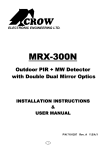
The RDK-4 is a proximity reader with
keypad, compatible with the AXS-100
access control system.
The system is designed to limit access
to restricted areas, while permitting
authorized people to enter. The RDK-4
can be programmed by the installer to
offer one of three security levels for
opening the door:
1. Valid tag only.
2. Valid tag and user PIN (Personal
Identification Number) code.
3. Password only.
Figure 1 - RDK-4
It is recommended to install the RDK-4 on a wall outside the
protected area, and the AXS-100 control unit inside the protected
area.
Proximity access cards or tags are used as keys to open doors.
When presented to an RDK-4, the access card or tag emit a coded
RF signal that is read by the proximity reader. The reader prompts
the user for a 4-digit PIN code (applicable to security level 2). When
the correct PIN code is typed, the control unit verifies that the card
is valid and makes the decision as to whether it should energize an
output relay that releases the lock. All activity involving the proximity
readers is recorded and logged by the AXS-100.
For information about the AXS-100 system, refer to the AXS-100
user’s guide and installation instructions.
2. SPECIFICATIONS
Power input: 12-16V DC From the AXS-100
Buttons: 12 (numeric keypad)
Frequency: 125 kHz
Tag reading range: 50 - 100 mm (2 - 4 in.)
Tag codes possibilities: 1012 possible combinations.
Cable (to AXS-100 control unit) maximum length:
100 m (320 ft)
Minimum distance between readers: 60 cm (2 ft)
Weight: 170 g (6 oz)
Color: Metallic brown
Dimensions (L x W x D): 122 x 82 x 31 mm
(4 - 13/16 x 3 - 1/2 x 1 - 1/4 in.)
Operating temperature: -20°C to 50°C (-4°F to 122°F)
3. MOUNTING
Mount the proximity reader outside the door on the wall or door
frame. The RDK-4 comes with a 1m (3 ft) cable.
Note: When installing more than one RDK-4, the distance
between the readers should be at least 60 cm (2 ft.), to ensure
proper operation.
To mount the proximity reader:
A. Remove the case closure screw.
B. Separate the base from the keypad assembly.
C. Place the base on the installation surface, mark points, drill
the holes and insert plastic anchors, if necessary.
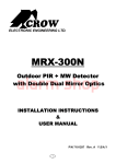
D. Fit the base into the rubber gasket and use the 2 mounting
screws to attach the base and gasket to the selected surface.
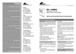
Figure 2 - Base and Gasket
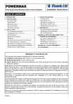
4. WIRING
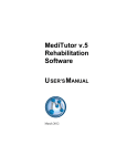
Each RDK-4 reader is connected to the control unit via a
four-wire cable. The standard cable is color-coded. Use a cable
with the same colors to avoid mistakes in connection. Connect
each proximity reader to the reader sections on the AXS-100
connector blocks. See diagram for color-coding.
RDK-4
AXS-100
AXS-100XT
READER 1/2
PWR
GND
TX
RX
Red
Black
Green
White
Figure 3 - Connection to AXS-100
DE6321
1
5. SECURITY LEVEL SELECTION
The RDK-4 can be programmed by the installer to offer one of
three security levels, as shown in the next table.
No.
Security level
Security level selection
description
1 The door is unlocked No jumper is not installed .
by presentation of a
valid tag/card only.
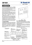
2 Door is unlocked by Select this security level by either
presentation of a valid of the following actions:
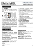
tag/card followed by A. Install jumper in the RDK-4.
B. Connect shorting wire
user PIN code
between D.POS & GND
keying.
terminals in the RDK-4 (see
fig. 4).
C. Set To/From time in minutes,
in AXS-100 registers 8 & 9
(for Reader 1) or registers 10
& 11 (for Reader 2), to
determine the period during
which the RDK-4 will switch
from security level 1 (tag
only) to security level 2 (tag +
PIN). For example, if you
want that the security level 2
will be valid from 12 o’clock
(720 min.) to 13 o’clock (780
min.), set AXS-100 register 8
to 720 and register 9 to 780.
For details, refer to AXS-100
User Guide par. 3.2.7.
3 Door is unlocked by Set AXS-100 password as
described in the AXS-100 User
Password keying
followed by pressing Guide par. 3.3.3.
the # key
Jumper
Figure 4
Selecting Security
Level 2 by Using
a Jumper
WARRANTY
6. USING THE RDK 4
To enroll an access card refer to the AXS-100 User Manual section
3.3.1 Add Keys. The PIN code of each card is automatically defined
by the AXS-100. In order to receive the PIN codes for access cards,
please refer to the AXS-100 User Manual section 5.2.1 Setup Flags.
To enter a door, present a valid tag to the RDK-4. If your RDK-4 is
programmed to operate by tag and user’s PIN code, present the tag
and then enter the PIN code within 5 seconds.
When presented to an RDK-4, the access card or tag emits a coded
RF signal that is read by the proximity reader. The reader prompts the
user for a 4-digit PIN code by blinking the yellow light. If no PIN code
is typed within 10 seconds, or a wrong PIN code is typed, the red LED
will light up.
A delay of more than 5 seconds, between presenting a tag and
starting to key user PIN code, or between any two digits, cancels the
operation.
The normal functions of the LEDs are summarized in the following
table.
LED
Green
Red
{
{
{
Yellow
Visonic Networks Ltd. and/or its subsidiaries and its affiliates ("the Manufacturer") warrants its
products hereinafter referred to as "the Product" or "Products" to be in conformance with its
own plans and specifications and to be free of defects in materials and workmanship under
normal use and service for a period of twelve months from the date of shipment by the
Manufacturer. The Manufacturer's obligations shall be limited within the warranty period, at its
option, to repair or replace the product or any part thereof. The Manufacturer shall not be
responsible for dismantling and/or reinstallation charges. To exercise the warranty the product
must be returned to the Manufacturer freight prepaid and insured.
This warranty does not apply in the following cases: improper installation, misuse,
failure to follow installation and operating instructions, alteration, abuse, accident or
tampering, and repair by anyone other than the Manufacturer.
This warranty is exclusive and expressly in lieu of all other warranties, obligations or
liabilities, whether written, oral, express or implied, including any warranty of
merchantability or fitness for a particular purpose, or otherwise. In no case shall the
Manufacturer be liable to anyone for any consequential or incidental damages for breach
of this warranty or any other warranties whatsoever, as aforesaid.
This warranty shall not be modified, varied or extended, and the Manufacturer does not
authorize any person to act on its behalf in the modification, variation or extension of this
warranty. This warranty shall apply to the Product only. All products, accessories or
attachments of others used in conjunction with the Product, including batteries, shall be
covered solely by their own warranty, if any. The Manufacturer shall not be liable for any
damage or loss whatsoever, whether directly, indirectly, incidentally, consequentially or
otherwise, caused by the malfunction of the Product due to products, accessories, or
attachments of others, including batteries, used in conjunction with the Products.
Indicates that an invalid tag was presented or
an invalid PIN was entered.
Remains lit to indicate that power is on. In
security level 2, blinks after the tag is accepted,
to prompt the user for PIN.
Job Control
There is an option that when a valid exit occurs, the exit will be
reported (Time & Attendance exit), if the reader is defined in EXIT
mode (see AXS-100 user guide, section 4). To implement this option,
ther are 2 possibilities:
1. Before opening the door, press the “∗” key in the RDK-4.
2. Before opening the door, press the RTE switch (see fig. 5).
RDK-4
external
reader
Function
Indicates that a valid tag was presented and
the output relay was activated.
RTE
switch
Figure 5
RTE switch
RDK-4
external
reader
The Manufacturer does not represent that its Product may not be compromised and/or
circumvented, or that the Product will prevent any death, personal and/or bodily injury
and/or damage to property resulting from burglary, robbery, fire or otherwise, or that the
Product will in all cases provide adequate warning or protection. User understands that a
properly installed and maintained alarm may only reduce the risk of events such as
burglary, robbery, and fire without warning, but it is not insurance or a guarantee that
such will not occur or that there will be no death, personal damage and/or damage to
property as a result.
The Manufacturer shall have no liability for any death, personal and/or bodily injury
and/or damage to property or other loss whether direct, indirect, incidental,
consequential or otherwise, based on a claim that the Product failed to function.
However, if the Manufacturer is held liable, whether directly or indirectly, for any loss or
damage arising under this limited warranty or otherwise, regardless of cause or origin, the
Manufacturer's maximum liability shall not in any case exceed the purchase price of the
Product, which shall be fixed as liquidated damages and not as a penalty, and shall be
the complete and exclusive remedy against the Manufacturer.
Warning: The user should follow the installation and operation instructions and among
other things test the Product and the whole system at least once a week. For various
reasons, including, but not limited to, changes in environmental conditions, electric or
electronic disruptions and tampering, the Product may not perform as expected. The user
is advised to take all necessary precautions for his /her safety and the protection of
his/her property.
6/91
TECHNICAL DEPT.:
39 HAMELACHA ST. CARMIEL 20100 ISRAEL TEL: 972 4 9081115 FAX: 972 4 9081116
Tech. Support email:
[email protected]; [email protected]
SALES DEPT.:
30 HABARZEL ST. TEL AVIV 69710 ISRAEL TEL: 972 3 645 6789 FAX: 972 3 645 6891
VISONIC INC. (U.S.A.): 10 NORTHWOOD DRIVE, BLOOMFIELD CT. 06002-1911. TEL: (860) 243-0833, (800) 223-0020 FAX: (860) 242-8094
VISACCESS LTD. (UK): UNIT 1, STRATTON PARK, DUNTON LANE, BIGGLESWADE, BEDS. SG18 8QS. TEL: (01767)600857 FAX: (01767)601098
www.visonicnet.com
INTERNET:
Visonic Networks Ltd. 2002
RDK-4 DE6321- (REV. 1, 12/02)
2
DE6321