1
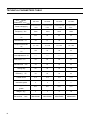
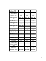
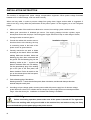
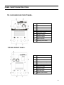
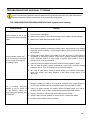
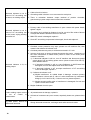
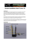
TIG 160S/200S/250S/300S
TIG 200A/250A/300A
WELDING MACHINE
USER MANUAL
Preface
This manual includes hardware description and operation introduction of the equipment TIG 160S/200S
/250S/300S/200A/250A/300A. For your and other people’s safety, please read the manual carefully.
Pay attention
Pay attention to the words after the signs below.
Sign
Description
The words after this sign means there is great potential danger,
which may cause major accident, damage or even death, if it is not
followed.
The words after this sign means there is some potential danger,
which may cause hurt or property lose, if it is not followed.
The words after this sign means there is potential risk, which may
cause equipment fault or break, if it is not followed.
Version
Version YF-TAE-0043, A0, Released at 22th, 4, 2013.
The contents of this manual are updated irregularity for updating of product. The manual is only used as
operation guide, except for other promises. No warranties of any kind, either express or implied are made in
relation to the description, information or suggestion or any other contents of the manual.
The images shown here are indicative only. If there is inconsistency between the image and the actual
product, the actual product shall govern.
CONTENTS
SAFETY WARNING ........................................................................................................................................... 4
MACHINE DESCRIPTION ................................................................................................................................. 5
TECHNICAL PARAMETERS TABLE ................................................................................................................. 6
INSTALLATION INSTRUCTION ......................................................................................................................... 8
PANEL FUNCTION INSTRUCTION ................................................................................................................... 9
OPERATION INSTRUCTION ........................................................................................................................... 11
NOTES OR PREVENTIVE MEASURES ......................................................................................................... 12
QUESTIONS TO BE RUN INTO DURING WELDING ..................................................................................... 13
MAINTENANCE................................................................................................................................................ 14
NOTES BEFORE CHECK ................................................................................................................................ 14
TROUBLESHOOTING AND FAULT FINDING ................................................................................................. 15
3
SAFETY WARNING
On the process of welding or cutting, there will be possibility of injury, so please take
protection into consideration during operation. For more details please review the
Operator Safety Guide, which complies with the preventive requirements of the
manufacturer.
Electric shock——May lead to death !
!
l
Set the earth fitting according to applying standard.
l
Forbidden to touch the bare electric parts and electrode with uncovered skin, wet gloves or clothes.
l
Make sure you are insulated from the ground and the workshop.
l
Make sure you are in safe position.
Gases and fumes——May be harmful to health!
l
Keep your head out of the gases and fumes.
l
When arc welding, ventilators or air extractors should be used to avoid breathing gases.
Arc rays——Harmful to your eyes, burn your skin.
l
Wear suitable protective mask, light filter and protective garment to protect eyes and body.
l
Prepare suitable protective mask or curtain to protect looker-on.
Fire
l
Welding spark may cause fire, make sure there is no tinder stuff around the welding area.
Noise——Excessive noises will be harmful to hearing .
l
Use ear protector or others means to protect ear.
l
Warn looker-on that noise is harmful to hearing.
Malfunction——When trouble happens, contact with authorized professionals
l
If trouble happens during installation and operation, please follow this manual instruction to check up.
l
If you fail to fully understand the manual, or fail to solve the problem with the instruction, you should
contact the suppliers or the service center for professional help.
WARNING!
Creepage-protecting switch should be added when using the machine!
!
!
4
MACHINE DESCRIPTION
Welding machine is a rectifier adopting the most advanced inverter technology.
The development of welding equipment benefits from the appearance of the inverter power supply theory
and components. Inverter arc welding power source utilizes high-power component MOSFET to transfer
50/60Hz frequency up to 100KHz, then reduce the voltage and commutate, and output high-power voltage
via PWM technology. Because of the great reduce of the main transformer’s weight and volume; the
efficiency increases by 30%. The appearance of inverter welding equipment is considered to be a revolution
for welding industry.
Welding power source can offer stronger, more concentrated and more stable arc. When stick and work
piece get short, its response will be quicker. It means that it is easier to design into welding machine with
different dynamic characteristics, and it even can be adjusted for specialty to make arc softer or harder.
TIG welding machine is easy for arc initiation and has the functions of arc initiation current, arc stop current,
welding current, basic value current, current ascending time, current descending time, gas delay time,
continuous adjustment. What’s more, pulse frequency and pulse duty can also be adjusted independently. It
has the characteristics of automatic control of arc initiation, arc stop and stable arc, which make the best
result for shape and inner quality of the welding surface. Its exclusive design is specially suitable for bicycle
industry.
The machine can be for multi-use, and can weld stainless steel, carbon steel, copper and other color metal,
and also can use for traditional electric welding. Its transfer efficiency is above 85%.
Thanks for purchasing our products and looking forward to your precious advice, we will try our best to
perfect our products and service
WARNING!
The machine is mainly used in industry. It will produce radio wave, so the worker should
make fully preparation for protection.
5
TECHNICAL PARAMETERS TABLE
Model
TIG 160S
TIG 200S
TIG 250S
TIG 300S
1PhaseAC220V
1 PhaseAC220V
1PhaseAC220V
1PhaseAC220V
±15%
±15%
50/60
50/60
50/60
50/60
20.4
28
40
50
40
41
46
30
10~160
10~200
20~250
10~300
16.4
18
20
22
——
——
——
——
Duty cycle(%)
60
60
60
60
No-load loss (W)
40
40
40
60
Arcing way
HF
HF
HF
HF
Efficiency (%)
80
80
80
80
Power factor
0.73
0.73
0.73
0.73
Insulation grade
F
F
F
F
IP21
IP21
IP21
IP21
Weight(kg)
9
9
9
19
Dimensions (mm)
400×153×291
400×153×291
400×153×291
480×204×303
Parameters
Power voltage(V)
Frequency(Hz)
Rated input current
(A)
No-load volt.(V)
Output current volt.
(A)
Rated working volt.
(V)
Force adjustment(A)
Housing protection
grade
6
±15%
±15%
Model
Parameters
Power voltage(V)
Frequency(Hz)
TIG 200A
TIG 250A
TIG 300A
1PhaseAC220V
1 PhaseAC220V
1 PhaseAC220V
±15%
±15%
±15%
50/60
50/60
50/60
Rated input current
ARC
43
ARC
58
ARC
58
(A)
TIG
28
TIG
38
TIG
51
No-load volt.(V)
Output current volt.
(A)
41
56
56
10~200
5~250
10~300
Rated working volt.
ARC
28
ARC
30
ARC
30
(V)
TIG
18
TIG
20
TIG
22
——
0~100
0~100
Duty cycle(%)
60
60
35
No-load loss (W)
40
60
60
Arcing way
HF
HF
HF
Efficiency (%)
80
80
80
Power factor
0.73
0.73
0.73
Insulation grade
F
F
F
IP21
IP21
IP21
Weight(kg)
9
19
19
Dimensions (mm)
400×153×291
480×204×303
480×204×303
Force adjustment(A)
Housing protection
grade
7
INSTALLATION INSTRUCTION
The machine is equipped with power voltage compensation equipment. When power voltage fluctuates
between±15% of rated voltage, it still can work normally.
When use long cable, in order to prevent voltage form going down, bigger section cable is suggested. If
cable is too long, it may affect the performance of the power system. So we suggest you to use configured
length.
1.
Make sure intake of the machine not blocked or covered, lest cooling system could not work.
2.
Make good connection of shielded gas source. Gas supply passage includes cylinder, argon
decompress flow meter and pipe. Connecting part of pipe should use hoop or other things to fasten,
lest argon leaks out and air gets in.
3.
Ground the cables with section area no
Installation diagram
2
less than 6mm to the housing, the way
is connecting screw in the back of the
power source to ground device
4.
Correctly connect the arc torch or holder
according to the sketch. When use MMA
welding: Make sure the cable, holder and
fastening plug have been connected with
the ground. Put the fastening plug into the
fastening socket at the “-” terminal and
fasten it clockwise. When use TIG welding:
Put the gas-electricity plug of the welding
gun to the joint at the front panel, and
fasten clockwise. Put the air switch on the
gun to the relevant joint at the front panel,
and fasten the screw.
5.
Put the fastening plug of the cable to
fastening socket of “+” terminal at the front panel, fasten it clockwise, and the earth clamp at the other
terminal clamps the work piece.
6.
According to input voltage grade, connect power cable with power supply box of relevant voltage
grade. Make sure there is no mistake and the voltage of power supply does not exceed permission
range.. After the above job,installation is finished and welding is available.
WARNING!
Before connecting operation please make sure all the power is turned off. The right order
is to connect the welding cable and ground cable to the machine first, and make sure they are firmly
connected and then put the power plug to the power source.
8
PANEL FUNCTION INSTRUCTION
TIG 160S/200S/250S FRONT PANEL:
1
Power switch
2
Power indicator
3
Abnormal indicator
4
Welding current adjustment
5
Gas delay switch
6
Negative output
7
Positive output
8
Gas connector
9
Welding torch switch
1
Current meter
2
Abnormal indicator
3
Power switch
4
Welding current adjustment
5
Down slope switch
6
Negative output
7
Positive output
8
Gas connector
9
Welding torch switch
TIG300S FRONT PANEL:
9
TIG 200A FRONT PANEL:
1
Power switch
2
Power indicator
3
Abnormal indicator
4
Welding current adjustment
5
TIG/STICK switch
6
Negative output
7
Positive output
8
Gas connector
9
Welding torch switch
TIG 250A/300A FRONT PANEL:
1
Power switch
2
Abnormal indicator
3
Current meter
4
Welding current adjustment
5
ARC force current
adjustment
6
TIG/ARC switch
7
Negative output
8
Positive output
9
Gas connector
10
Welding torch switch
The panel picture above is for reference only. If any difference with the real machine, please follow with the
real machine.
10
OPERATION INSTRUCTION
TIG WELDING DESCRIPTION
1. Turn on the power switch of front panel, digital current meter is normal, fan begins to run.
2. Turn on argon switch, and adjust gas pressure to rated value.(refer to flow table)
3. Press switch of torch, electromagnetic valve is started. You will hear the sound of electricity-releasing HF
sparkle and at the same time, argon gets out the torch. NOTES: If the first time welding, you should
press switch for a few seconds before welding, until all the air in the gas passage is removed, and then
start to weld. When you stop welding, argon will still flow out for a few seconds, which is designed to
guarantee that weld spot is protected before cooling down. So when the electric arc stops , keep the
welding position for a while and then move the torch
4. Set suitable welding current according to the thickness of work piece and process demand.
5. Keep 2-4mm space between tungsten pole and work piece, press torch control switch, between
electrode and work piece HF electricity is released; After arc initiation ,HF sparkle disappears soon and
can start to work.
STICKING DESCRIPTION
1. Turn on the power switch on the front panel, and the fan begins to work.
2. Make sure function switch of front panel is on “down” position that is sticking. When welding jaw nips
welding rod, it begins to work;
3. According to work piece’s thickness, position, craftwork state, choose suitable welding current.
WARNING:
It is forbidden to pull out or put in the cable or connector during the process of welding,
which will threat life safety and damage the machine.
11
NOTES OR PREVENTIVE MEASURES
1. Environment
1) The machine should be operated in dry environments with humidity levels of max 90%.
2) Ambient temperature should be between -10 to 40 degrees centigrade.
3) Avoid welding in sunshine or drippings. Do not let water infiter the machine.
4) Avoid welding in dust area or the environment with corrosive gas.
5) Avoid gas welding in the environment with strong airflow.
2. Safety norms
The welding machine is installed with protection circuit of over voltage, over current and over heat. When
voltage, output current and temperature of machine exceed the required standard, welding machine will
stop working automatically. However, overuse (such as over voltage) will still result in damage to the
welding machine. To avoid this, the user must pay attention to the following.
1) The working area is adequately ventilated!
The welding machine is powerful machine, when it is being operated, it generated by high currents,
and natural wind will not satisfy machine cool demands. So there is a fan in inner-machine to cool
down machine. Make sure the intake is not in block or covered, it is 0.3 meter from welding
machine to objects of environment. User should make sure the working area is adequately
ventilated. It is important for the performance and the longevity of the machine.
2) Do not over load!
The operator should remember to watch the max duty current (Response to the selected duty
cycle). Keep welding current is not exceed max duty cycle current. Over-load current will damage
and burn up machine.
3) No over voltage!
Power voltage can be found in diagram of main technical data. Automatic compensation circuit of
voltage will assure that welding current keeps in allowable range. If power voltage is exceeding
allowable range limited, it will damage to components of machine. The operator should understand
this situation and take preventive measures.
4) There is a grounding screw behind welding machine, with a grounding marker on it. Before
operation, welding crust must be grounded reliable with cable which section is over 6 square
millimeter, in order to prevent from static electricity, and accidents because of electricity leaking.
5) If welding time is exceeded duty cycle limited, welding machine will stop working for protection.
Because machine is overheated, temperature control switch is on “ON’’ position and the indicator
light is red. In this situation, you don’t have to pull the plug, in order to let the fan cool the machine.
When the indicator light is off, and the temperature goes down to the standard range, it can weld
again.
12
QUESTIONS TO BE RUN INTO DURING WELDING
Fittings, welding materials, environment factor, supply powers maybe have something to do with welding.
User must try to improve welding environment.
A.
Black welding spot
——Welding spot is not prevented from oxidizing .User may check as following ::
1.
Make sure the valve of argon cylinder is opened and its pressure is enough. argon cylinder must be
filled up to enough pressure again if pressure of cylinder is be low 0.5Mpa .
2.
Check if the flow meter is opened and has enough flow .User can choose different flow according to
welding current in order to save gas .But too small flow maybe cause black welding spot because
preventive gas is too short to cover welding spot .We suggest that flow of argon must be kept min
3L/min.
3.
Check if torch is in block.
4.
If gas circuit is not air-tight or gas is not pure can lower welding quality.
5.
If air is flowing powerfully in welding environment , that can lower welding quality .
B. Arc-striking is difficult and easy to pause
1.
Make sure quality of tungsten electrode is high.
2.
Grind end of the tungsten electrode to taper .If tungsten electrode is not grinded , that will be difficult to
strike arc and cause unstable arc .
C. Output current not to rated value
When power voltage departs from the rated value, it will make the output current not matched with rated
value; When voltage is lower than rated value, the max output may lower than rated value.
D. Current is not stabilizing when machine is being operated
It has something with factors as following:
1. Electric wire net voltage has been changed.
2. There is harmful interference from electric wire net or other equipment.
E.
When use MMA welding ,too much spatter
1. Maybe current is too big and stick’s diameter is too small;
2. Output terminal polarity connection is wrong, it should apply the opposite polarity at the normal technics,
which means that the stick should be connected with the negative polarity of power source, and work
piece should be connected with the positive polarity. So please change the polarity.
13
MAINTENANCE
WARNING:
Power must be turned off for all checking and maintenance, before
opening the housing, make sure the power plug is disconnected.
1. Remove dust by dry and clean compressed air regularly, if welding machine is operated in environment
where is polluted with smokes and polluted air, the machine need remove dust every month.
2. Pressure of compressed air must be inside the reasonable arrangement in order to prevent damaging to
small components of inner-machine.
3. Check internal circuit of welding machine regularly and make sure the cable .Circuit is connected
correctly and connectors are connected tightly (especially insert connector and components). If scale and
loose are found, please give a good polish to them, then connect them again tightly.
4. Avoid water and steam enter into inner-machine, if them enter into machine, please dry inner-machine
then check insulation of machine.
5. If welding machine will not be operated for long time, it must be put into packing box and stored in dry
environment.
NOTES BEFORE CHECK
WARNING
Blind experiment and careless repair may lead to more problems and make formal check and repair
more difficult. When the machine is electrified, the bared parts contain life-threatening voltage. Any
direct and indirect touch will cause electric shock, and severe electric shock will lead to death.
14
TROUBLESHOOTING AND FAULT FINDING
Notes: The following operations must be performed by qualified electricians with valid certifications.
Before maintenance,please contact with us for professional suggestion.
TIG 160S/200S/250S/300S/200A/250A/300A fault symptom and remedy.
Fault symptom
Remedy
1. Power switch is damaged.
Power indicator is not lit, fan
does not work and no welding 2. Make sure the electric wire net connecting to input cable is working alright
output.
3. Make sure if input cable has broken circuit.
1. Input cable is possibly connected to 380V power, which causes over voltage
protection circuit is starting. Connect input cable to 220V power, then restart
the machine.
Power indicator switch is lit,
fan is not working or revolves
several circles and stopped,
no welding output.
2. Erratic 220V power supply (input cable is too thin and long) or input cable is
connected to electricity network would start overload voltage protection
circuit. Increase section of input cable or tighten input contact. Turn off
machine for 2-3 min and restart it.
3. Cable that connects switch and power board is loosed, tighten it again.
4. Turn on and off power switch continuously would start overload voltage
protection circuit. Turn off machine for 2-3 min and restart it.
5. 24V relay of main return circuit on power board is not closed or damaged,
check 24V power and relay. Replace it with same model series if it’s
damaged.
1. Measure voltage of positive and negative electrode from power board to
VH-07 insert of MOS board by multimeter, which should reads DC 308V.
Fan is working, abnormal
indicator is not lit, sound of 2. There is a green indicator for auxiliary power on MOS board, if it’s not lit,
auxiliary power is out of work, check fault spot and contact with dealer.
HF arc striking cannot be
heard, wiping arc welding can 3. Check if all kinds of connect and insert cable is poor contact.
not strike arc.
4. Check if there is some problem in control circuit, contact with dealer.
5. Check if control cable of torch is broken.
15
1. Cable of torch is broken.
Abnormal indicator is not lit,
sound of HF arc-striking can 2. Grounding cable is broken or not connected to work piece.
be heard, no welding output
3. There is relaxation between output terminal of positive electrode,
gas-electricity system output terminal and inner machine.
1. Primary cable of arc-striking transformer is poor contact with power board,
tighten it again.
Abnormal indicator is not lit,
sound of HF arc-striking can 2. Arc-striking tip is oxidized or distance is too far, get rid of film oxide of burner
or adjust the distance between burners to be 1mm.
not be heard, wiping welding
can strike arc.
3. MMA/TIG switch is damaged, replace it.
4. Some HF arc striking components is damaged, check and replace it.
1. Overload current protection may start, please turn off machine first, then
restart it after abnormal indicator is off.
2. Overheat protection may start, it will become normal in 2-3 min.
3. Inverter circuit may go wrong, please disconnect the power supply plug of
the main transformer on MOS board (close to insert of fan VH-07) then
restart the machine.
1) If abnormal indicator is still on, turn off machine and disconnect power
supply plug of HF arc-striking power source (close to insert of fan VH-07),
then restart machine:
Abnormal indicator is lit, no
welding output.
a) If abnormal indicator is still on, some fieldistors on MOS board are
damaged ,find out and replace them with same model .
b) If abnormal indicator is off, up-slope transformer of HF arc-striking
circuit is damaged, replace it.
2) If abnormal indicator is off:
a) Maybe transformer on middle board is damage, measure primary
inductance volume and Q value of main transformer by inductance
bridge (L=0.9-1.6mH Q>35) .If value is too low ,please replace it .
b) Maybe second rectifier tube of transformer is damaged, find out and
replace it with same model
4. Maybe feedback circuit is open.
Erratic welding output current 1. 1K potentiometer is damage, replace it.
or
out
of
control
of
2. All kinds of connectors are poor contact, especially inserts etc, please check
potentiometer.
it.
Big MMA spatter, difficult for
alkalescent electrode
16
Wrong electrode connection, exchange earth cable and torch cable.