1
APPLICATION NOTE
Using GHS Compiler with RH850
RH850, GHS Compiler, Linker
R20AN0330ED0200
Rev. 2.00
Oct. 27, 2014
Introduction
When programming the Renesas RH850, the user is focusing on various, sometimes very different goals, like saving
code size, improving runtime or even an improvement of real time behavior. In consequence it is a must for modern C
compilers for embedded systems to offer target specific extensions like keywords and pragmas as well as special
support of the features of the microcontroller.
The purpose of this document is to give recommendations on code and RAM optimization for the Renesas RH850
microcontroller family using the GHS compiler. Some recommendations in this document are general and some are
specific to the RH850 or GHS compiler.
This guideline’s main goal is to enable the user making efficient use of the standard GHS compiler (V6.1.4/2013.5.5 or
later) targeting the Renesas RH850 MCU family.
Target Device
RH850, F1x/D1x/P1x families
R20AN0330ED0200 Rev. 1.00
Oct. 27, 2014
Page 1 of 25
Using GHS Compiler with RH850
RH850, GHS Compiler, Linker
Contents
1.
Common Compiler Options ........................................................................................... 3
1.1
2.
MCAL recommended Options.................................................................................................... 3
RH850 Dedicated Solutions ........................................................................................... 4
2.1
Bit Manipulation .......................................................................................................................... 4
2.1.1
Bit manipulation of an 8-bit location. ....................................................................................... 4
2.1.2
Bit manipulation of a 16/32-bit access .................................................................................... 4
2.1.3
Forced Bit instruction .............................................................................................................. 4
2.2
General Hints for Code Optimization ........................................................................................ 5
2.2.1
Language Dependent Settings ............................................................................................... 5
2.2.2
CPU Architecture dependent settings ..................................................................................... 5
2.3
Utilize RH850 Memory models ................................................................................................... 7
2.3.1
General ................................................................................................................................... 7
2.3.2
Mixing Memory Models ........................................................................................................... 8
2.4
Useful compiler settings ............................................................................................................ 9
2.5
Helping the Compiler Optimizer ................................................................................................ 9
2.5.1
Local Variables Should be of Type Integer ........................................................................... 10
2.5.2
Look-up Tables ..................................................................................................................... 11
2.5.3
Switch Against if/else ............................................................................................................ 12
2.6
Pipeline Hazards ....................................................................................................................... 13
2.6.1
System Register Access ....................................................................................................... 14
2.6.2
Precautions for Peripheral Accesses .................................................................................... 15
3.
Working with Sections ................................................................................................. 16
3.1
Pulling Code Into a User Defined Section .............................................................................. 16
3.2
Pulling Data Into A User Defined Section ............................................................................... 16
3.2.1
Compiler Option Independent Allocation .............................................................................. 17
3.3
Allocating (Module) Sections in the Linker Directive File ..................................................... 17
3.4
Creating new (combined) Sections ......................................................................................... 17
4.
Variable Alignment ....................................................................................................... 19
5.
CPU Core Selection ...................................................................................................... 20
Website and Support ........................................................................................................... 21
Revision History .................................................................................................................... 1
General Precautions in the Handling of MPU/MCU Products ............................................. 2
Figure 1 Memory Models .................................................................................................................................................. 7
R20AN0330ED0200 Rev. 1.00
Oct. 27, 2014
Page 2 of 25
Using GHS Compiler with RH850
1.
1.1
RH850, GHS Compiler, Linker
Common Compiler Options
MCAL recommended Options
The following set of options is agreed for testing and running the compiler, in case the Renesas MCAL package is used.
Please note: Other, non MCAL related modules may use other options!
This defines the debug level, the option -G is usually NOT required and recommended. It has to be seen as a special
case. It requires min. 1kByte additional RAM and is usable for Multi Debugger only. The debug option will prevent the
optimizer from being too drastic, which means loop unrolling and inlining would happen on very limited places, even if
-Ogeneral or -Ospeed would be used.
-g
This option defines the basic optimization strategy. Along with -prepare_dispose and -linline_prologue and -no_callt it
may provide nearly the same level of optimization as –Ogeneral, but no loop unrolling and automatic lining is done!
-Ospace
# in some cases, also –Ospeed might be possible
-prepare_dispose # to make sure inlined prologue is efficient
-inline_prologue # make sure that inline prologue is generated (with
# -Ospace)
-no_callt
# make sure that no slow callt is used
Enables the basic small data addressing mode (provided by the RH850 core) and makes the generated code more
efficient
-sda=all
Optionally one may provide the large SDA addressing mode and advice the linker to shorten the variable access back to
signed 16-bit. This makes sense for devices with more than 64kByte RAM and 64kByte constant data.
-large_sda
The next quest is to enable some more warnings, like checking the availability of prototypes or just undefined macros.
--prototype_errors
-Wundef
Only the options below are common to ALL project modules inside and outside MCAL. They may NOT be changed or
altered in the system build.
-reserve_r2
# setting required for some tools
--short_enum
# Make enumerations non-ANSI standard shorter
# than integer
-dual_debug
# make sure that other source debuggers have
# debug access
-cpu=rh850g3m
# or use rh850g3k
Finally, these are the options for the linker, valid for the entire project. The options -shorten_loads and –shorten_moves
make sure that 16-bit addressing mode is used wherever this is possible. This may save code size.
-shorten_loads
# replace 23-bit offsets with 16-bit, where possible
-shorten_moves
# replace 23-bit offsets with 16-bit, where possible
-delete
# delete functions, which are unused
R20AN0330ED0200 Rev. 1.00
Oct. 27, 2014
Page 3 of 25
Using GHS Compiler with RH850
2.
RH850, GHS Compiler, Linker
RH850 Dedicated Solutions
2.1
Bit Manipulation
The RH850 core has 4 different instructions available to deal with single bits in a memory/SFR address space. This may
be utilized by the compiler, if the target’s address is 8-bit wide only.
2.1.1
Bit manipulation of an 8-bit location.
Use char based types of bit fields to allow bit access.
struct T_BIT{
unsigned char b00:1;
unsigned char b01:1;
unsigned char b02:1;
unsigned char b03:1;
unsigned char b04:1;
unsigned char b05:1;
unsigned char b06:1;
unsigned char b07:1;
};
2.1.2
Bit manipulation of a 16/32-bit access
Please use a base type bigger than ‘char’ to define single bits within a memory location allowing only 32-Bit bus access.
struct T_LONGBIT{
unsigned long b00:1;
unsigned long b01:1;
unsigned long b02:1;
unsigned long b03:1;
unsigned long b04:1;
unsigned long b05:1;
unsigned long b06:1;
unsigned long b07:1;
};
The resulting code is not using any bit instruction by default and it is NOT thread save.
In this case, a thread safe bit manipulation may be implemented with the assistance of intrinsic functions defined in the
header file
<ghs-dir>\include\v800\v800_ghs.h
unsigned long
unsigned long
unsigned long
unsigned long
unsigned long
unsigned long
2.1.3
__INTERLOCKED_OR( volatile unsigned long *addr, unsigned long val);
__INTERLOCKED_AND( volatile unsigned long *addr, unsigned long val);
__INTERLOCKED_XOR( volatile unsigned long *addr, unsigned long val);
__INTERLOCKED_NOT( volatile unsigned long *addr, unsigned long val);
__INTERLOCKED_MOV( volatile unsigned long *addr, unsigned long val);
__INTERLOCKED_ANDOR( volatile unsigned long *addr, unsigned long mask,
unsigned long val);
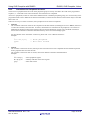
Forced Bit instruction
This last option may be found as well as intrinsic functions (for V5.x.x or later compiler only!).
void
void
void
int
__SET1( volatile char *addr, __ghs_c_int__ bitnum);
__CLR1( volatile char *addr, __ghs_c_int__ bitnum);
__NOT1( volatile char *addr, __ghs_c_int__ bitnum);
__TST1( volatile char *addr, __ghs_c_int__ bitnum);
R20AN0330ED0200 Rev. 1.00
Oct. 27, 2014
Page 4 of 25
Using GHS Compiler with RH850
2.2
RH850, GHS Compiler, Linker
General Hints for Code Optimization
This chapter offers some methods to write code optimized for the RH850 architecture. Here we differentiate between
optimizations concerning the C-language itself and those ones having a direct influence to the bus system and core
selection.
2.2.1
Language Dependent Settings
All local variables should be of type ‘unsigned/signed int’
o Avoid sign extension operations (results in bigger code …)
Transfer parameter (function parameter) should be of type ‘unsigned/signed int’ because the internal register
bus size is 32-bit.
o Avoid sign extension operations
Don’t use ‘volatile’ attribute on local variable
Consider large structure declarations in local context will have higher stack usage
Put all sequences, which are used more than one time, in a function.
Enable generic optimization –O
Remove unreferenced functions ‘-delete’
Inline functions, that are only called once
2.2.2
CPU Architecture dependent settings
Use SDA memory optimization
o no base register load required for memory access
o Fixed constant base register addressing (‘TP’-register)
Enable usage of prepare and dispose instructions on function prologue and epilogue. For RH850 cores, this is
o driver option: -prepare_dispose
Set “V850 Tiny Data Area” to “None”, because the special register (EP) used for this addressing mode may be
allocated automatically by the compiler in a rather intelligent manner.
o driver option: -notda
Enable inlined function pro- and epilogues
o -inline_prologue
Avoid a mixture of double/float FPU operations, where possible.
o If it is not possible, please have a look at this specification!
A floating point constant without ‘f’-suffix is of type double!
Example:
float ft;
…
if( ft> 1.0f) …
o
Any call to a subroutine expecting float parameter(s) without prototyping will lead into a disaster.
The parameter is always used as the native implementation, or at least converted to it under
ANSI C, thus it is handled as a type “double”.
As a result, it is most probably that the function will end up in a NaN exception!
(For integer this is not that meaningful, because “long” and “int” are the same size …)
Avoid unnecessary type conversions
For special high- speed functions, look for 3rd party FPU algorithms
o Maybe they offer less security features, but are faster …
R20AN0330ED0200 Rev. 1.00
Oct. 27, 2014
Page 5 of 25
Using GHS Compiler with RH850
RH850, GHS Compiler, Linker
Use the compiler option “-ffunctions”
o This makes sure that math functions are inlined
Some high-speed functions are used inline, but explicit calls may use the GHS runtime library, improving the
safety.
o Example:
return fabsf(f);
/* this results in a library call to fabsf */
o Workaround:
#define __ifabsf(f)
((f>0)? (f):-(f))
Do not try to pass local variables located in stack and its contents to higher level functions
o The runtime environment will be invalidated as soon as the sub function is finished.
(Invalidation of stack!)
R20AN0330ED0200 Rev. 1.00
Oct. 27, 2014
Page 6 of 25
Using GHS Compiler with RH850
2.3
RH850, GHS Compiler, Linker
Utilize RH850 Memory models
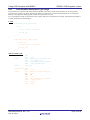
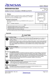
One of the more important issues of a Core is to understand, how it may address the memory spaces. The RH850 has a
mixture of 48-, 32 and 16-bit instructions, although it is a RISC type CPU. Any memory address is always addressed by
using a base register plus a signed offset, either 16-bit or 23-bit. That means in case the SDA addressing mode
(“-sda=all”) is selected, the base register is fixed and will not change over the whole runtime for all variables addressed
by the selected SDA mode. The base register for variables in RAM is ‘gp (r4)’ and for constants located in FLASH it is
‘tp (r5)’. Since both, constants and variables are addressed by separate base pointers, it is very important that a
declaration is identical to the definition of a symbol.
2.3.1
General
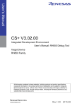
All memory models can be used at the same time
zero and small data optimization allow to access 192 KB of data
#pragma instructions or command line switches tell the compiler which memory model it should use for
data.
Figure 1 Memory Models
R20AN0330ED0200 Rev. 1.00
Oct. 27, 2014
Page 7 of 25
Using GHS Compiler with RH850
2.3.2
RH850, GHS Compiler, Linker
Mixing Memory Models
The different addressing modes SDA and ZDA are allowed to be used
In the same module
Across modules in the same project
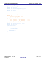
Using both modes simultaneously requires strong consistency over definition and declaration of the variables.
Example:
/*
* Module A.c
* Definition
*/
/*
* Module A.h
* Declarations
*/
__ZNEAR( const int, count1);
__SNEAR( long,
time);
__FAR(
long,
OtherCount);
__ZNEAR( extern const int, count1);
__SNEAR( extern long,
time);
__FAR(
extern long,
OtherCount);
Table 1 Symbol Definition/Declaration
Please note that the syntax used above is derived from C99 spec., using these definitions:
#define PRAGMA(x)
_Pragma(#x)
#define __SNEAR(type, x)
PRAGMA( ghs startsda)
type
x;
PRAGMA( ghs endsda);
\
\
#define __ZNEAR(type, x)
PRAGMA( ghs startzda)
type
x;
PRAGMA( ghs endzda);
\
\
#define __FAR(type, x)
PRAGMA( ghs startdata)
type
x;
PRAGMA( ghs enddata);
\
\
R20AN0330ED0200 Rev. 1.00
Oct. 27, 2014
Page 8 of 25
Using GHS Compiler with RH850
2.4
2.5
RH850, GHS Compiler, Linker
Useful compiler settings
-Ospeed for runtime critical modules
o compile to optimize execution speed
o turns on all the -O optimizations and the loop optimizations
-Osize –inline_prologue –no_callt –prepare_dispose for general use
o reduce code size (similar to driver options: -Osize and -OS)
o turns on all the -O optimizations except those which increase the code size
Also, one may use ‘-O’ or ‘-Ogeneral’, although it is not part of any certification process ongoing for the
current compiler 2013.5.5!
Generate debug information
o –g
o -G does also generate debug information, but also includes additional code for debugging, which may
be useful for testing and qualification. If this is used, you may call any subroutine any time in the
GHS debugger’s command line or script.
Instruct the compiler to stop with preprocessor output file (*.I)
o –P
(very useful to send to Renesas for support)
generate library (*.a)
o -archive
stop with assembler code
o -S
Generates an assembler list file with C/C++ source code
o -list -passsource
o This may also be used along with the ‘-S’ option.
Helping the Compiler Optimizer
There is NO general recipe do that, but generally speaking
Functions which are bigger, have more potential for the optimizer.
Only bigger modules may show improved optimization
That means smaller modules with smaller functions are harder to optimize!
Therefore new optimizations
“–OInterproc” and
“–Owholeprogram”
are introduced. They are optimizing the entire code, even sometimes at link stage.
As a consequence, it is sometimes harder to debug.
In general means inlining and loop unrolling the highest speed optimizations!
R20AN0330ED0200 Rev. 1.00
Oct. 27, 2014
Page 9 of 25
Using GHS Compiler with RH850
2.5.1
RH850, GHS Compiler, Linker
Local Variables Should be of Type Integer
Except for arrays, structures and unions which are placed on the stack, normal local variables are placed in general
purpose 32-bit registers. If a local variable is declared as a character or as a half-word and placed in a 32-bit register,
then for every operation modifying this variable, the sign bit has to be set.
It is in consequence using one more instruction (2 bytes) than if it was declared as an integer. The following example is
a simple illustration of what happens:
C Code
void read_stuct_int(void)
{
int i0;
for(i0 =0;i0 < 100;i0++)
{
S1.my_i++;
}
}
void read_stuct_char(void)
{
char i0;
for(i0 =0;i0 < 100;i0++)
{
S1.my_i++;
}
}
GHS Assembler Code
_read_stuct_int:
mov
0,r2
.L193:
ld.w zdaoff(_S1+4)[zero],r17
add
1,r2 add 1,r17
st.w r17,zdaoff(_S1+4)[zero]
addi -100,r2,zero blt
.L193
jmp [lp]
_read_stuct_char:
mov
.L193:
ld.w
add
sxb
add
st.w
addi
blt
jmp
R20AN0330ED0200 Rev. 1.00
Oct. 27, 2014
0,r2
zdaoff(_S1+4)[zero],r17
1,r2
r2
1,r17
r17,zdaoff(_S1+4)[zero]
-100,r2,zero
.L193
[lp]
Page 10 of 25
Using GHS Compiler with RH850
2.5.2
RH850, GHS Compiler, Linker
Look-up Tables
When having a long list of test in an if-statement or several if-statements, it is sometime an advantage for both speed
and size to use a lookup table.
The disadvantage is that, depending on the table declaration (global, const, local…), additional RAM, ROM or stack is
required e.g.:
C Code
int init_noLUT(int in)
{
int out;
in &=(8);
if((in == 0) ||(in == 2)||(in == 4)||(in == 6)||(in == 8))
out = 0xFA;
else out = -1;
return out;
}
char lookup_table[9] = {1,0,1,0,1,0,1,0,1};
int init_LUT(int in)
{
int out;
in &=(8);
if(lookup_table[in])
out = 0xFA;
else out = -1;
return out;
}
GHS Assembler Code
_init_noLUT:
andi
be
cmp
be
mov
jmp
.L5:
movea
.L2:
jmp
_init_LUT:
andi
movea
add
ld.b
cmp
cmove
jmp
8,r6,r1
.L5
8,r1
.L5
-1,r10
[lp]
250,zero,r10
[lp]
8,r6,ep
250,zero,r1
gp,ep
sdaoff(_lookup_table)[ep],r2
zero,r2
-1,r1,r10
[lp]
Most probably is the solution with a lookup table of higher interest, if the number of conditions is higher. Otherwise it is
more likely that the ordinary comparison is faster.
R20AN0330ED0200 Rev. 1.00
Oct. 27, 2014
Page 11 of 25
Using GHS Compiler with RH850
2.5.3
RH850, GHS Compiler, Linker
Switch Against if/else
The code generated when using an if/else or switch directive has approximately the same size as long as the case
number is less than 6. If the number of cases is bigger than 6, the compiler uses the V850 assembler instruction switch
in relation with a lookup table. The code is then smaller and faster. The difference in code size between switch and
if/else increases with the number of cases.
In consequence, the switch statement brings an advantage over the if/else statement when the number of case is greater
than 6.
Example of using a switch statement
C-Code
int init_switch(int in)
{
int out;
in &=(5);
switch (in)
{
case 0: out = 0xff;
case 1: out = 0xFe;
case 2: out = 0xFD;
case 3: out = 0xFC;
case 4: out = 0xFB;
case 5: out = 0xFA;
case 6: out = 0xF0;
default: out = -1;
}
return out;
}
break;
break;
break;
break;
break;
break;
break;
GHS Assembler Code
_init_switch:
andi
cmp
bnh
mov
jmp
.L6:
mov
add
ld.bu
.L2:
jmp
…
.table: .byte
5,r6,r6
6,r6
.L6
-1,r10
[lp]
r5,ep
r6,ep
sdaoff2(.table)[ep],r10
[lp]
255,254,253,252,251,250,240
Only 9 lines of operation are required to acquire the desired result. Each way requires the same execution time.
R20AN0330ED0200 Rev. 1.00
Oct. 27, 2014
Page 12 of 25
Using GHS Compiler with RH850
RH850, GHS Compiler, Linker
Below is the sample code of a if-else-statement bundle:
C-Code
int init_if_else(int in)
{
int out; in &=(5);
if(in == 0) out = 0xff;
else
{
if(in == 1) out = 0xFe;
else {
if(in == 2) out = 0xFD;
else {
if(in == 3) out = 0xFC;
else {
if(in == 4) out = 0xFB;
else {
if(in == 5) out = 0xFA;
else {
if(in == 6) out = 0xF0;
else out = -1;
}
}
}
}
}
}
return out;
}
GHS Assembler Code
_init_if_else:
andi
cmp
bh
mov
add
ld.bu
jmp
.L125:
cmp
be
movea
cmp
cmovne
jmp
.L115:
movea
jmp
…
.table: .byte
5,r6,r6
4,r6
.L125
r5,ep
r6,ep
sdaoff2(.table)[ep],r10
[lp]
5,r6
.L115
240,zero,r1
6,r6
-1,r1,r10
[lp]
250,zero,r10
[lp]
255,254,253,252,251
Although the compiler now utilizes the conditional mov instructions of the RH850, the advantage is still with the
switch- case implementation, also from point of view regarding the readability of the code.
2.6
Pipeline Hazards
The compiler includes several intrinsic functions to handle special requirements of the system co-processors as well as
requirements of the peripherals. Usually, the intrinsic functions can be found in the header file “v800_ghs.h” in this
directory
<ghs_install_dir\include\v800
R20AN0330ED0200 Rev. 1.00
Oct. 27, 2014
Page 13 of 25
Using GHS Compiler with RH850
2.6.1
RH850, GHS Compiler, Linker
System Register Access
Certain system registers require special procedures to resolve hazards, if their content is updated and used directly after
that operation. There is also a header file named “cpu.h”, which defines the access to these registers and which is
reflecting the access style. In future, the header file will be part of the device file package distribution.
Instruction fetching
When an instruction is to be fetched after updating a register covered by the description below, after executing
the instruction to update the register, only allow the instruction fetch to start after execution of an EIRET,
FERET, or SYNCI instruction.
o PSW.UM,MCFG0.SPID
When an instruction is to be fetched after updating a register covered by the description below, execute the
instruction to update the register before allowing the instruction fetch to start. - All registers related to ASID and
MPU (register number: SR*,5-7)
SYSCALL instruction
When a SYSCALL instruction is to be executed after updating the register below, execute a SYNCP
instruction after the instruction to update the register and before the SYSCALL instruction.
o SCCFG
Load/Store
When an instruction associated with Load/Store after updating the registers below, execute a SYNCP
instruction after executing the instruction to update the registers before Load/Store instruction.
o ASID,MPU protection area setting register (Register number: SR*,6-7)
Interrupt
Update the registers below when interrupt is inhibited. (PSW.ID=1).
o PSW.EBV,EBASE,INTBP,FPIPR,ISPR,PMR,ICSR,INTCFG
Operation to clear instruction cache
When completion of instruction cache clearance is confirmed, check the read value of the ICCTRL.ICHCLR
bit.
FPU register update
After executing update instruction of the registers below, execute a SYNCP instruction.
o
Change of FPP/FPI exception mode
When the FPP/FPI exception mode is changed, execute instructions of SYNCP and SYNCE first, and update
the register below. To update registers, proceed “FPU register update” above also.
o
All FPU-related registers (Register number: SR6-11,0)”
FPSR.PEM
Coprocessor instruction
When a coprocessor instruction (floating-point operation instruction) is to be executed after updating the
register below, execute instructions of EIRET, FERET or SYNCI after executing the instruction to update the
registers and before executing a coprocessor instruction.
o
PSW.CU0
R20AN0330ED0200 Rev. 1.00
Oct. 27, 2014
Page 14 of 25
Using GHS Compiler with RH850
2.6.2
RH850, GHS Compiler, Linker
Precautions for Peripheral Accesses
The accesses to peripherals that are in the same peripheral group are strictly executed in the order of the programmed
sequence, i.e. a read after write will wait until the write transaction is completed.
Accesses to peripherals, which are connected to different busses or different peripheral groups, are not necessarily in the
programmed order. Due to different bus latencies and buffers, a transaction that has been issued earlier may be executed
after a later one.
There are two ways to ensure in software, that a peripheral access has been completed.
SYNCM
The “SYNCM”-instruction waits for the completion of all data transfers (excluding the access to HBUS, instruction
or other CPU transfers) from the CPU. It ensures, that the data was transferred to the peripheral, even if there are
additional bus bridges or FIFO stages between the CPU and the destination register. The “SYNCM”-instruction
ensures that a transaction reached its final destination by return of an acknowledge signal.
For more details on the “SYNCM”- instruction, please refer “User’s Manual: Software”.
Example:
…
st.w r10,0[r1]
syncm
…
-- Write peripheral
-- Wait until written
SYNCP
The “SYNCP”-instruction ensures, that all previous instructions have been completed and the read data requested
from a peripheral has arrived at the CPU.
The “SYNCP”-instruction does not ensure, that written data has reached its final destination.
Example:
…
st.w r10,0[r1]
ld.w 0[r1],r10
syncp
…
-- Write peripheral register
-- Dummy read back of the same register
-- Wait until written
R20AN0330ED0200 Rev. 1.00
Oct. 27, 2014
Page 15 of 25
Using GHS Compiler with RH850
3.
RH850, GHS Compiler, Linker
Working with Sections
The compiler offers also different ways to allocate text or data into user defined sections. This allocation is differently
handled for text and for data. Not supported is the allocation of a single global variable to a particular address.
3.1
Pulling Code Into a User Defined Section
The simplest method of changing a code section name is like this:
#pragma ghs section “.text”= “.mytext0”
…
void foo( void) { … }
…
#pragma ghs section “.text”= default
If this is done, the section needs to be known by the linker. Best place to do this, is to add the new section to the linker
directive file.
SECTIONS
{
…
.text align(4)
:>. /* align to word */
.mytext0 abs(0x4000) :>. /* locate the section to address 0x4000 */
…
}
3.2
Pulling Data Into A User Defined Section
Depending on the default addressing mode selected for the compiler, data is always stored in a section, which is directly
related to the default one:
Data Type
Initialized data
Uninitialized data
Default Section
Target section
.data
-sda=all
.sdata
-zda=all
.zdata
.bss
.sbss
.zbss
If it is desired to place variables in the default addressing mode, like sda for example, the expression is getting simpler:
#pragma ghs section sbss=”.mysbss”
int svar;
#pragma ghs section sbss=default
#pragma ghs section sdata=”.mysdata”
int svarInit=0x55aaee11;
#pragma ghs section sdata=default
Please make sure, that the variable to be placed here is indeed part of the SDA (sbss) address space, otherwise the
allocation will not work properly and no linker warning is issued!
R20AN0330ED0200 Rev. 1.00
Oct. 27, 2014
Page 16 of 25
Using GHS Compiler with RH850
3.2.1
RH850, GHS Compiler, Linker
Compiler Option Independent Allocation
The allocation of any variable into a user defined section independent of the compiler options would require a special
handling. In case the addressing mode of the variable is NOT necessarily required in any special addressing mode,
continue like this:
#pragma
#pragma
…
#pragma
#pragma
…
#pragma
#pragma
ghs startdata
/* Makes sure that any data is moved to default*/
ghs section bss=”.mybss0”
ghs section bss=default
ghs section data=”.mydata0”
ghs section data=default
ghs enddata
Please keep in mind, that the linker directives require some adaptation to place the new sections properly.
3.3
Allocating (Module) Sections in the Linker Directive File
Another method of section allocation may be to change the directive file only, just by allocating new sections for each
module having a particular section in use.
Here is an example of a method how to place all text sections used in modules of a library into a special text section:
.text
align(4)
:>.
.libtext align(4)
:
{
crt0.o (*(.text))
libarch.a (*(.text))
}
> .
3.4
/* program code area */
/* library code area */
Creating new (combined) Sections
Another method to combine the sections appearing in one or more modules into a single section means to manipulate
both, the source module(s) and the linker directive file.
The example below shows a combination of both, a special vector table and a text module to be placed into the Flash
area of the device.
.hvctext align(256)
{
*(.hvcall_tbl)
*(.vec1_text)
}
:
/* a new text section is created */
>.
/* containing a table defined in assembler */
/* and interrupt handlers defined in ‘C’ */
/* program memory (images, fonts etc.) */
All sections named with “.hvcall_tbl” and “.vec1_text” are grouped and sequentially placed into the section “.hvctext”.
R20AN0330ED0200 Rev. 1.00
Oct. 27, 2014
Page 17 of 25
Using GHS Compiler with RH850
RH850, GHS Compiler, Linker
There is only minimum effort required in the C-modules to create such sections. The above sample is referring to two
different types of sections, which are grouped and defined in assembler as well as in C:
#pragma ghs startdata
#pragma ghs section rodata=".hvcall_tbl"
extern const uint32_t HVC_OFFSETS[];
#pragma ghs section rodata=default
#pragma ghs enddata
/* The block below is assembler language, since it
* incorporates techniques, a compiler cannot fulfill
*/
#pragma asm
.section ".hvcall_tbl", "ro"
.globl
_HVC_OFFSETS
_HVC_OFFSETS:
.word (_HVC_Vec1 - _HVC_OFFSETS)
-- + 12
.word (_HVC_Vec0 - _HVC_OFFSETS)
-- + 8
.word (_HVC_Vec1 - _HVC_OFFSETS)
-- + 4
.word (_HVC_Vec0 - _HVC_OFFSETS)
-- + 0
#pragma endasm
#pragma ghs section text=".vec1_text"
#pragma ghs noprologue
void HVC_Vec0(void)
{
FETRAP_ENTRY();
/* Change RBASE */
… ;
FETRAP_LEAVE();
}
R20AN0330ED0200 Rev. 1.00
Oct. 27, 2014
Page 18 of 25
Using GHS Compiler with RH850
4.
RH850, GHS Compiler, Linker
Variable Alignment
Green Hills provides by default the ANSI compatible alignment of variables. Thus, the linker sorts variables according
to its size and alignment in memory.
The alignment can easily be given using a special ‘pragma’- instruction to be placed before the variable is implemented
like this:
#pragma alignvar(4)
unsigned short ctl0;
Alternatively, also the ‘attribute’- notation may be used:
__atribute__(( aligned(8) )) unsigned char xtra;
To do this for multiple variables, just repeat the pragma instruction
#pragma alignvar(4)
unsigned short ctl0;
#pragma alignvar(4)
unsigned short ctl0;
Or feel free to create new data types automatically aligning variables:
typedef unsigned short T_us16_64 __attribute__((aligned(8)));
typedef unsigned char T_uc16_64 __attribute__((aligned(8)));
T_us16_64
T_uc8_64
share_state0;
share_foo;
The above method allocates each variable of these types on 64-bit boundary!
There is no further action required …
Members of structures of this type are affected, too!
Arrays are not affected, only with starting address!
R20AN0330ED0200 Rev. 1.00
Oct. 27, 2014
Page 19 of 25
Using GHS Compiler with RH850
5.
RH850, GHS Compiler, Linker
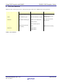
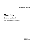
CPU Core Selection
GHS may select various types of cores, starting from legacy V800 cores to RH850 of the latest generation
‘-cpu=‘ Option
Core Name
FPU type
Sample
v850
All non ‘E‘ type cores
S/W
Very old devices ...
v850e
All E/ES/E1F types
E1F has H/W FPU (single)
Fx2/Fx3/Jx2/Jx3 and
all Pho cores
v850e2v3
All E2M and E2K types
E2M core has H/W FPU
Fx4, Dx4 Fx4-L and
Px4 devices
V850e3v5
H/W (double)
rh850
rh850g3k
S/W (default option)
G3M, G3K and G3H
core family
S/W
rh850g3m
H/W double
rh850g3h
H/W double
RH850 Device Family
Table 2 Core Selection
R20AN0330ED0200 Rev. 1.00
Oct. 27, 2014
Page 20 of 25
Using GHS Compiler with RH850
RH850, GHS Compiler, Linker
Website and Support
Renesas Electronics Website
http://www.renesas.com/
Helpdesk
[email protected]
Inquiries
http://www.renesas.com/contact/
R20AN0330ED0200 Rev. 1.00
Oct. 27, 2014
Page 21 of 25
Using GHS Compiler with RH850
RH850, GHS Compiler, Linker
All trademarks and registered trademarks are the property of their respective owners.
R20AN0330ED0200 Rev. 1.00
Oct. 27, 2014
Page 22 of 25
Revision History
Rev.
1.00
2.00
Date
10/1/2014
10/27/2014
Description
Page
Summary
Initial Version
Update Table 2 Core Selection
A-1
General Precautions in the Handling of MPU/MCU Products
The following usage notes are applicable to all MPU/MCU products from Renesas. For detailed usage notes on the
products covered by this document, refer to the relevant sections of the document as well as any technical updates that
have been issued for the products.
1. Handling of Unused Pins
Handle unused pins in accordance with the directions given under Handling of Unused Pins in the
manual.
The input pins of CMOS products are generally in the high-impedance state. In operation with
an unused pin in the open-circuit state, extra electromagnetic noise is induced in the vicinity of
LSI, an associated shoot-through current flows internally, and malfunctions occur due to the
false recognition of the pin state as an input signal become possible. Unused pins should be
handled as described under Handling of Unused Pins in the manual.
2. Processing at Power-on
The state of the product is undefined at the moment when power is supplied.
The states of internal circuits in the LSI are indeterminate and the states of register settings and
pins are undefined at the moment when power is supplied.
In a finished product where the reset signal is applied to the external reset pin, the states of
pins are not guaranteed from the moment when power is supplied until the reset process is
completed.
In a similar way, the states of pins in a product that is reset by an on-chip power-on reset
function are not guaranteed from the moment when power is supplied until the power reaches
the level at which resetting has been specified.
3. Prohibition of Access to Reserved Addresses
Access to reserved addresses is prohibited.
The reserved addresses are provided for the possible future expansion of functions. Do not
access these addresses; the correct operation of LSI is not guaranteed if they are accessed.
4. Clock Signals
After applying a reset, only release the reset line after the operating clock signal has become
stable. When switching the clock signal during program execution, wait until the target clock signal
has stabilized.
When the clock signal is generated with an external resonator (or from an external oscillator)
during a reset, ensure that the reset line is only released after full stabilization of the clock
signal. Moreover, when switching to a clock signal produced with an external resonator (or by
an external oscillator) while program execution is in progress, wait until the target clock signal is
stable.
5. Differences between Products
Before changing from one product to another, i.e. to a product with a different part number, confirm
that the change will not lead to problems.
The characteristics of an MPU or MCU in the same group but having a different part number
may differ in terms of the internal memory capacity, layout pattern, and other factors, which can
affect the ranges of electrical characteristics, such as characteristic values, operating margins,
immunity to noise, and amount of radiated noise. When changing to a product with a different
part number, implement a system-evaluation test for the given product.
Notice
1.
Descriptions of circuits, software and other related information in this document are provided only to illustrate the operation of semiconductor products and application examples. You are fully responsible for
the incorporation of these circuits, software, and information in the design of your equipment. Renesas Electronics assumes no responsibility for any losses incurred by you or third parties arising from the
use of these circuits, software, or information.
2.
Renesas Electronics has used reasonable care in preparing the information included in this document, but Renesas Electronics does not warrant that such information is error free. Renesas Electronics
assumes no liability whatsoever for any damages incurred by you resulting from errors in or omissions from the information included herein.
3.
Renesas Electronics does not assume any liability for infringement of patents, copyrights, or other intellectual property rights of third parties by or arising from the use of Renesas Electronics products or
technical information described in this document. No license, express, implied or otherwise, is granted hereby under any patents, copyrights or other intellectual property rights of Renesas Electronics or
others.
4.
You should not alter, modify, copy, or otherwise misappropriate any Renesas Electronics product, whether in whole or in part. Renesas Electronics assumes no responsibility for any losses incurred by you or
third parties arising from such alteration, modification, copy or otherwise misappropriation of Renesas Electronics product.
5.
Renesas Electronics products are classified according to the following two quality grades: "Standard" and "High Quality". The recommended applications for each Renesas Electronics product depends on
the product's quality grade, as indicated below.
"Standard": Computers; office equipment; communications equipment; test and measurement equipment; audio and visual equipment; home electronic appliances; machine tools; personal electronic
equipment; and industrial robots etc.
"High Quality": Transportation equipment (automobiles, trains, ships, etc.); traffic control systems; anti-disaster systems; anti-crime systems; and safety equipment etc.
Renesas Electronics products are neither intended nor authorized for use in products or systems that may pose a direct threat to human life or bodily injury (artificial life support devices or systems, surgical
implantations etc.), or may cause serious property damages (nuclear reactor control systems, military equipment etc.). You must check the quality grade of each Renesas Electronics product before using it
in a particular application. You may not use any Renesas Electronics product for any application for which it is not intended. Renesas Electronics shall not be in any way liable for any damages or losses
incurred by you or third parties arising from the use of any Renesas Electronics product for which the product is not intended by Renesas Electronics.
6.
You should use the Renesas Electronics products described in this document within the range specified by Renesas Electronics, especially with respect to the maximum rating, operating supply voltage
range, movement power voltage range, heat radiation characteristics, installation and other product characteristics. Renesas Electronics shall have no liability for malfunctions or damages arising out of the
use of Renesas Electronics products beyond such specified ranges.
7.
Although Renesas Electronics endeavors to improve the quality and reliability of its products, semiconductor products have specific characteristics such as the occurrence of failure at a certain rate and
malfunctions under certain use conditions. Further, Renesas Electronics products are not subject to radiation resistance design. Please be sure to implement safety measures to guard them against the
possibility of physical injury, and injury or damage caused by fire in the event of the failure of a Renesas Electronics product, such as safety design for hardware and software including but not limited to
redundancy, fire control and malfunction prevention, appropriate treatment for aging degradation or any other appropriate measures. Because the evaluation of microcomputer software alone is very difficult,
please evaluate the safety of the final products or systems manufactured by you.
8.
Please contact a Renesas Electronics sales office for details as to environmental matters such as the environmental compatibility of each Renesas Electronics product. Please use Renesas Electronics
products in compliance with all applicable laws and regulations that regulate the inclusion or use of controlled substances, including without limitation, the EU RoHS Directive. Renesas Electronics assumes
no liability for damages or losses occurring as a result of your noncompliance with applicable laws and regulations.
9.
Renesas Electronics products and technology may not be used for or incorporated into any products or systems whose manufacture, use, or sale is prohibited under any applicable domestic or foreign laws or
regulations. You should not use Renesas Electronics products or technology described in this document for any purpose relating to military applications or use by the military, including but not limited to the
development of weapons of mass destruction. When exporting the Renesas Electronics products or technology described in this document, you should comply with the applicable export control laws and
regulations and follow the procedures required by such laws and regulations.
10. It is the responsibility of the buyer or distributor of Renesas Electronics products, who distributes, disposes of, or otherwise places the product with a third party, to notify such third party in advance of the
contents and conditions set forth in this document, Renesas Electronics assumes no responsibility for any losses incurred by you or third parties as a result of unauthorized use of Renesas Electronics
products.
11. This document may not be reproduced or duplicated in any form, in whole or in part, without prior written consent of Renesas Electronics.
12. Please contact a Renesas Electronics sales office if you have any questions regarding the information contained in this document or Renesas Electronics products, or if you have any other inquiries.
(Note 1)
"Renesas Electronics" as used in this document means Renesas Electronics Corporation and also includes its majority-owned subsidiaries.
(Note 2)
"Renesas Electronics product(s)" means any product developed or manufactured by or for Renesas Electronics.
SALES OFFICES
http://www.renesas.com
Refer to "http://www.renesas.com/" for the latest and detailed information.
Renesas Electronics America Inc.
2801 Scott Boulevard Santa Clara, CA 95050-2549, U.S.A.
Tel: +1-408-588-6000, Fax: +1-408-588-6130
Renesas Electronics Canada Limited
1101 Nicholson Road, Newmarket, Ontario L3Y 9C3, Canada
Tel: +1-905-898-5441, Fax: +1-905-898-3220
Renesas Electronics Europe Limited
Dukes Meadow, Millboard Road, Bourne End, Buckinghamshire, SL8 5FH, U.K
Tel: +44-1628-585-100, Fax: +44-1628-585-900
Renesas Electronics Europe GmbH
Arcadiastrasse 10, 40472 Düsseldorf, Germany
Tel: +49-211-6503-0, Fax: +49-211-6503-1327
Renesas Electronics (China) Co., Ltd.
Room 1709, Quantum Plaza, No.27 ZhiChunLu Haidian District, Beijing 100191, P.R.China
Tel: +86-10-8235-1155, Fax: +86-10-8235-7679
Renesas Electronics (Shanghai) Co., Ltd.
Unit 301, Tower A, Central Towers, 555 Langao Road, Putuo District, Shanghai, P. R. China 200333
Tel: +86-21-2226-0888, Fax: +86-21-2226-0999
Renesas Electronics Hong Kong Limited
Unit 1601-1613, 16/F., Tower 2, Grand Century Place, 193 Prince Edward Road West, Mongkok, Kowloon, Hong Kong
Tel: +852-2265-6688, Fax: +852 2886-9022/9044
Renesas Electronics Taiwan Co., Ltd.
13F, No. 363, Fu Shing North Road, Taipei 10543, Taiwan
Tel: +886-2-8175-9600, Fax: +886 2-8175-9670
Renesas Electronics Singapore Pte. Ltd.
80 Bendemeer Road, Unit #06-02 Hyflux Innovation Centre, Singapore 339949
Tel: +65-6213-0200, Fax: +65-6213-0300
Renesas Electronics Malaysia Sdn.Bhd.
Unit 906, Block B, Menara Amcorp, Amcorp Trade Centre, No. 18, Jln Persiaran Barat, 46050 Petaling Jaya, Selangor Darul Ehsan, Malaysia
Tel: +60-3-7955-9390, Fax: +60-3-7955-9510
Renesas Electronics Korea Co., Ltd.
12F., 234 Teheran-ro, Gangnam-Ku, Seoul, 135-920, Korea
Tel: +82-2-558-3737, Fax: +82-2-558-5141
© 2014 Renesas Electronics Corporation. All rights reserved.
Colophon 4.0