1
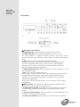
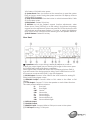
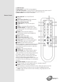
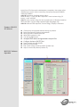
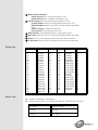
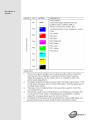
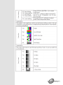
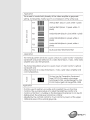
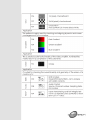
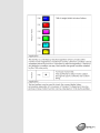
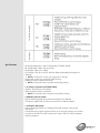
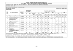
HDMI V1.3 Pattern Generator ID# 727 Operation Manual Introduction This HDMI v1.3 compliant video test patter generator is the most advance device for your audio & video signals test. With built-in 39 timings and 51 patterns that accept both analog and digital signals provide over thousand types of testing signals. This handy device can be conveniently controlled via the front panel buttons or the IR remote and a LCD screen for easy viewing. Other then testing your devices this generator can also check the resolution of your devices and record them, check bandwidth and phase behavior transmission, verity video amplifiers/color temperature/video motion plus HDCP verification, data comparison, EDID check and many more useful functions. Application Apparatus testing Equipment adjustment EDID check Source setting define HDCP verification System Requirements Video and or audio source input with connecting cables and output display and or speaker(s) with connecting cables. Features HDMI v1.3, HDCP v1.1 and DVI v1.0 compliant Provides 39 timings and 51 patterns Timing included SD, HD up to 1080p, PC up to UXGA/WUXGA (Reduce Blanking Pixel Rate at 154MHz) Patterns include Graphic Test Patterns and Data Analysis Patterns Output format with digital HDMI/DVI, or analog PC/HD (component) Color Space supports RGB444, YCbCr444 and YCbCr422 Deep Color supports 8 / 10 / 12 bits Audio source is selectable among external 7.1CH, optical or internal sinewave Internal sinewave LPCM channel is selectable from 2CH, 5.1CH and 7.1CH Supports HDCP test Support EDID data analysis. Support HDMI/DVI input data analysis. Support Autorun function Choose [My Favorite] timings and patterns through RS-232 using PC software that included in the box. Friendly user interface - LCD display, LED indicators, IR remote and RS232 remote Operation Controls and Functions Front Panel ② IR Remote Control Sensor. ③ Timing Selection: Switch between timings from T01 to T39. ④ Pattern Selection: Switch between patterns from P01 to P51. For some patterns, it supports OPTION function. After enter option function and then press Pattern up/down button to adjust the Brightness level. ⑤ AUTO: Turn ON/OFF Autorun Demonstration Function. Using PC software through RS-232, users can select timings among T01~T39 and patterns among P01~P51 for Autorun demonstration. When Autorun is turn on, the systems will automatically running the selection timings/patterns sequentially. ⑥ Output Format Selection: Press the button to switch between PC, HD, DVI and HDMI output. ⑦ FAV.: Turn ON/OFF Favorite Function. When switch on the Favorite function, users can select only the favorite timings and favorite patterns. Users need to select favorite timings among T01~T39 and favorite patterns among P01~P51 by using PC software through RS-232. When switch off the Favorite function, users can select all the timings and patterns. ⑧ HDCP ON/OFF: Turn ON/OFF the HDCP encryption. When the LED illuminate it means the HDCP encryption is on. ⑨ Audio Source Selection: Press the button to switch between External 7.1CH(analog), external optical(digital) or internal sinewave audio source. ⑩ LPCM Channel Selection: Press the button to switch between 2CH, 5.1CH or 7.1CH LPCM audio channels. ⑪ Color Space Selection: Press the button to switch between RGB444, YCbCr444 or YCbCr422 color space. ⑫ System Reset: Press two buttons at the same time to reset the system back to factory mode. During the system reset the LCD Display will show "SYSTEM RESET" message. ⑬ Deep Color Selection: Press the button to switch between 8bits, 10bits or 12 bits deep colors. ⑭ EDID Pattern: Pattern 32 hot key. ⑮ OPTION: Not all the Patterns support function adjustments, when screen shows “Press [OPTION] to do the setting” that means this pattern support function adjustment. When user press the OPTION button the LED will illuminate and then press Pattern +/- button to adjust the Brightness level. Switch off the OPTION function before go to next pattern selection. ⑯ HDCP Pattern: Pattern 39 hot key. Rear Panel ① OVERSCAN: When output timing is 480i59/60,480p59/60, 576i50 or 576p50, the output signal may not showing full image on the screen, press the OVERSCAN button to fill screen completely. When signal under OVERSCAN mode, the LCD Display will show STAR (*) sign at the end of the timing resolution string. Press OVERSCAN to turn off the overscan mode and the STAR (*) sign will disappear. ② PC/HD Output: Connect VGA cable to the VGA monitor for analog PC timing or HD timing signal output. ③ HDMI/DVI Output: Connect HDMI or DVI cable to the HDMI or DVI display. ④ 7.1CH Output: Connect 7.1CH to the speaker or Audio Video Receiver. The audio printed definition as below: FL: Front Left, FR: Front Right, CNT: Center, SUB: Subwoofer, SL: Surround Left SR: Surround Right, SBL: Surround Back Left, SBR: Surround Back Right. ⑤ OPTICAL Output. ⑥ COAXIAL Output. ⑦ HDMI/DVI Input: Connect HDMI or DVI Input source to the system. ⑧ 7.1CH Input: Analog 7.1CH Inputs. ⑨ OPTICAL Input ⑩ Power Input: Plug 5V DC power adaptor. ⑪ RS-232 Connection: Connect RS-232 cable between this system and PC. Using PC software to control this system through RS-232 port. ⑫ Power Switch: Turn ON/OFF the system. Remote Control ① HDCP ON/OFF: Turn ON/OFF HDCP encryption. ② Color Space Selection: Switch between RGB444, YCbCr444 or YCbCr422. ③ Output Timing Selection ④ OUTPUT ON: Turn ON/OFF the option function. ⑤ Timing - : Backward Timing Selection. ⑥ AVMUTE ENABLE: For HDMI output, press to mute the Audio. The LCD Display will show "AVMUTE ON". ⑦ AUDIO: Switch between External 7.1CH(analog), external optical(digital) or internal sinewave. ⑧ EDID: Pattern 32 hot key. ⑨ Output Format Selection: Switch between PC, HD, DVI or HDMI output. ⑩ Output OFF: Switch off the output signal. The LCD Display will show "OUTPUT OFF". ⑪ Pattern +: Next Pattern Selection. For some patterns, it supports OPTION function. After entering into option function and then press Pattern up/down buttons to adjust the Brightness level. ⑫ Timing +: Next Timing Selection. ⑬ OPTION(OK): Not all the Patterns support function adjustments, when screen shows “Press [OPTION] to do the setting” that means this pattern support function adjustment. When user press the OPTION button the LED will illuminate and then press Pattern +/button to adjust the Brightness level. Switch off the OPTION function before go to next pattern selection. ⑭ AVMUTE DISABLE: For HDMI output, press to mute the Audio. The LCD display will show “disable AVMUTE”. ⑮ Pattern -: Backward Pattern Selection. For some patterns, it supports OPTION function. After enter option function and then press Pattern up/down button to adjust the Brightness level. Note> Open remote control cover of battery, using dip-switch to set controller address. Built-In Rx Edid Structure: The system support 4 sets Built-in Rx EDID, one is active and others are for backup. The Active EDID will copy the EDID from backup EDID. (Go to "System Setup" function) The system will copy the Sink EDID and built-in into Rx EDID to analysis display information. RS-232 PC software programs can support Rx EDID contents. RS-232 Connection and Protocol: Connection between the unit and remote controller with RS-232 modem cable (No Wire Crossing). Pin definition RS-232 transmission formats: Baud Rate=19200bps Data Bit=8bits Parity=None Stop Bit=1bit Flow Control=None Command / Response codes of RS-232 transmission: note 1: After computer sends command to the system, computer has to wait for response from the system. Then computer can send next command to the system. If this system is under autorunning, RS-232 communications maybe fail. note 2: To configure Autorun follows a sequence of commands --- ATNxxx + ATTxxx + ATPxxx + ATIxxx … note 3: If this system is not on Pattern 47.Color Setting, respond CRR300, CRG300, CRB300 or CRY300. note 4: Procedure of setting RX EDID name string : send "ERX00?" -> wait "ERX00?" response -> send name string (12 bytes) -> wait "ERX004" note 5: In the name string, the rest unused bytes (<12bytes) should be filled with 0x00. note 6: After ERX99? response, name string (12 bytes) is followed. note 7: After ERD001 response, this system reads sink's EDID and transmits them (datastream) to remote terminal. If this system reads sink's EDID fail, the system sends '0xfe' and stop datastream. This system supports 2-block EDID, datastream length=block0+block1=256 bytes note 8: After ERS001 response, this system erases sink's EDID and fill with 'FF'. After erase completely, the system response is ERS002 If erase fails, the system response is ERS003 note 9: After EWR001 response, this system will waits for EDID datastrem(256 bytes) from PC After receive datastream completely, the system writes datastream to sink. If write successfully, the system responses EWR002, otherwise EWR003 note 10: Procedure of setting custom string : send "MOT001" -> wait "MOT001" response -> send custom string (12 bytes) -> wait "MOT002" note 11: In the custom string, the rest unused bytes (<12bytes) should be filled with 0x00. Custom string supports English language only. note 12: After MOT999 response, custom string (12 bytes) is followed. Features of RS-232 PC Software RS-232 PC Software Operation Click button and upload selected timing or pattern. Select [My Favorite] timings and patterns. Read out EDID contents from sink. Write EDID contents to sink. Can be an EDID burner. Analyze EDID data and generate a report file. Configure Autorun [AUTO] List. Panel Controls through RS-232 Monitors System status. Edit custom string of Motion Pattern (Pattern 46). Adjust color-levels pattern (Pattern 47). ① Main Function Selection: Timing Select:Select a timing among T01~T39 Pattern Select:Select a pattern among P01~P51 ① Favorite Timing:Select favorite timings among T01~T39 Favorite Pattern: Select favorite patterns among P01~P51 EDID Read/Write: Read, write EDID contents and analyze EDID data. Autorun Config: Configure autorun list. Panel Control: Control system functions. ② Status Monitor: Click [Refresh] button to get system status. ③ Work Area: Different main functions have independent work area. ④ About: Get PC software and system firmware version number. ⑤ RS-232 Setup: Select RS-232 Comport and turn on/off connection. Timing Table No. T01 T02 T03 T04 T05 T06 T07 T08 T09 T10 T11 T12 T13 T14 T15 T16 T17 T18 T19 T20 Pattern Table Resolution 640x480 640x480 640x480 640x480 800x600 800x600 800x600 800x600 800x600 1024x768 1024x768 1024x768 1024x768 1280x960 1280x960 1280x1024 1280x1024 1280x1024 1600x1200 1920x1200 V Hz 60 72 75 85 56 60 72 75 85 60 70 75 85 60 85 60 75 85 60 60 No. T21 T22 T23 T24 T25 T26 T27 T28 T29 T30 T31 T32 T33 T34 T35 T36 T37 T38 T39 Resolution 720x480i 720x480i 720x480p 720x480p 1280x720p 1280x720p 1920x1080i 1920x1080i 1920x1080p 1920x1080p 720x576i 720x576p 1280x720p 1920x1080i 1920x1080p 1920x1080p 1920x1080p 1366x768 1366x768 V Hz 59 60 59 60 59 60 59 60 59 60 50 50 50 50 50 23 24 60 50 Graphic Test Patterns: 45 Patterns Data Analysis Patterns: 6 Patterns (Include P32, P38, P39, P48, P49, P50) P01 WHITE P24 MULTI-BURST P02 BLUE P25 Plug P03 RED P26 GRID-1 P04 MAGENTA P27 GRID-36 P05 GREEN P28 GRAY-256-R P06 CYAN P29 GRAY-256-G P07 YELLOW P30 GRAY-256-B P08 BLACK P31 CIRCLES P09 RED Setting P32 EDID P10 GRN Setting P33 H Grey Scale P11 BLUE Setting P34 Horizontal .RGB Bar P12 GRAY Setting P35 SMPT Bar P13 COLOR BAR P36 Split Bar P14 GRAY-8 P37 CROSS HATCH P15 GRAY-16 P38 AUDIO P16 GRAY-32 P39 HDCP P17 GRAY-64 P40 Win Blue P18 GRAY-256 P41 Win Red P19 V line ONOFF P42 Win Magenta P20 BW-12 P43 Win Green P21 H line ONOFF P44 Win Cyan P22 HOR.-3 P45 Win Yellow P23 HOR.-6 P46 Motion P47 Color Setting P48 Rx Timing P49 Rx Video P50 Rx Audio P51 RGB Delay System Setup Description of Patterns Specifications 39 Timings: 480 x 640 ~ 1366 x 768 (Details in TIMING TABLE) SD timings: 480i , 480p, 576i and 576p HD timings: 720p up to 1080p PC timings: VGA up to UXGA, WUXGA (Reduce Blanking Pixel Rate at 154MHz) NOTE > Analog PC output only supports PC timings Analog HD output only supports SD/HD timings HDMI/DVI output support all timings NOTE > This system didn't support user timing editing ● 51 Patterns: (Details in PATTERNS TABLE) Graphic Test Patterns: 45 Patterns Data Analysis Patterns: 6 Patterns NOTE > This system didn't support user pattern editing ● HDMI/DVI Input & Output: Signal: TMDS single link and clock bandwidth up to 225MHz Connector: HDMI TYPE-A. DVI input needs DVI to HDMI adaptor ● Analog PC/HD Output: Signal: Analog R/G/B/H/V or analog YPbPr are support color space conversion. Component HD outputs support tri-level sync and color space conversion. Connector: D-SUB15. For HD component output, DB15 to 3-RCA adaptor cable is required. ● Video Color Space and Deep Color: HDMI Output: RGB444(8/10/12bits), YCbCr444(8/10/12bits) and YCbCr422(8bits) DVI Output:RGB444(8bits) PC Output: RGB with separate sync H/V or YPbPr with separate sync H/V and without composite sync on Y. HD Output: YPbPr with composite sync on Y or RGB with composite sync on G. ● Audio Inputs: External Analog 7.1CH: RCA jacks. External Optical: Toslink jack. Internal Sinewave: Supports LPCM 2CH, 5.1CH and 7.1CH. Supports Sampling Rate 48KHz, 96KHz and 192KHz (Refer to Audio Output) Sinewave Frequency: FL (Front Left)=1000Hz, FR (Front Right)=600Hz, CNT (Center)=800Hz, SUB (Subwoofer)=400Hz, SL (Surround Left)=1200Hz, SR¹ (Surround Right)=1400Hz, SBL (Surround Back Left)=1600Hz, SBR (Surround Back Right)=1800Hz NOTE> This system didn't support bitstream (Dolby, DTS) decoding from external optical. ● Audio Output: Analog 7.1CH: RCA jacks. Optical: Toslink jack. Coaxial: RCA jack. HDMI: Support I2S bus control. Pattern 38: Audio control functions please refer to below table. (SR1=Samping Rate) 2CH: FL (Front Left) and FR (Front Right). 6CH: FL (Front Left), FR (Front Right), CNT (Center), SUB (Subwoofer), SL (Surround Left) and SR² (Surround Right) ● Pattern 32 - EDID Analysis: The EDID sources can form three different ways and support 2 block analysis. The system will copy the Sink EDID and built-in into Rx EDID to analysis display information. Below are the three different ways to get the EDID: 1. Built-in Rx EDID 2. From Display HDMI/DVI Sink EDID 3. From Display VGA EDID The EDID analyses are follow VESA E-EDID v1.3 and EIA/CEA 861D Version 3 standard. ● Pattern P39 - HDCP Analysis: This system will do the HDCP handshaking and link-integrity test and it also support Sink Repeater BKSV list and V’ values. ● HDMI/DVI Input Analysis: Support manual Hot-plug (Press [OPTION]) Pattern 48: HDMI/DVI Video Timing Detection and Analysis Pattern 49: HDMI/DVI Video Packets and Infoframe Detection and Analysis. Pattern 50: HDMI Audio Packets and Infoframe Detection and Analysis. ● User Interface: LCD display, LED indicators, IR remote, RS-232 remote: D-SUB9 female connector. PC software supports RS-232 remote control.