1
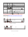
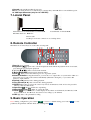
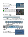
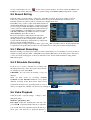
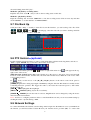
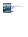
Digital Video Recorder
Quick Guide
This manual is to help you set up your DVR in a basic manner, and playback or remote access
your DVR. Please see the User Manual on included CD for more detailed instructions.
0
Table of Contents
1.
2.
3.
4.
Important Safeguards and Warnings........................................................................................................ 2
Package Contents .................................................................................................................................... 2
Hard Disk Installation if not pre-installed ............................................................................................... 2
Top Panel ................................................................................................................................................. 3
(a)Top panel for 10”LCD DVR............................................................................................................... 3
(b) Top panel for 15”LCD DVR and 19”LCD DVR............................................................................... 3
5. Front Panel Please take actual machine mode as quasi .................................................................... 3
6. Rear Panel(Please take actual machine model as quasi) ......................................................................... 4
7. Lateral Panel............................................................................................................................................ 6
8. Remote Controller ................................................................................................................................... 6
9. Basic Operation ....................................................................................................................................... 6
9.1 Login System..................................................................................................................................... 7
9.2 Live View .......................................................................................................................................... 7
9.3 Status and Tool Bar ........................................................................................................................... 7
9.4 HDD Management ............................................................................................................................ 7
9.5 Record Setting ................................................................................................................................... 8
9.5.1 Manual Recording .................................................................................................................. 8
9.5.2 Schedule Recording................................................................................................................ 8
9.6 Video Playback .................................................................................................................................. 8
9.7 File Back Up...................................................................................................................................... 9
9.8 PTZ Control—(optional) ................................................................................................................... 9
9.9 Network Settings ............................................................................................................................... 9
10. Web Operation....................................................................................................................................... 10
11. Wap Connection .................................................................................................................................... 11
12. Mobile Phone Support........................................................................................................................... 11
(
)
1
1. Important Safeguards and Warnings
•
•
Don’t place heavy objects on the DVR. Avoid dropping or striking the DVR.
Keep the DVR in a normal room environment, between 0oC ~ +45oC, away from any direct heat source
like direct sun light. Please do not install the DVR in a damp, smoky, or dusty environment. Do not
let solids or liquids fall into or infiltrate the DVR.
•
•
•
Please install the DVR on a flat surface.
Use within the power and surge protection rating.
Don’t disassemble or try to repair the DVR by yourself. Attempts to do so will void manufacturer’s
warranty!
2. Package Contents
Your DVR package should come with the following items:
•
•
•
•
•
•
•
DVR
Remote Control
Power Adapter and Power Cord
CD (with full manual and DVR software)
This Quick Guide
Mouse (optional)
Installed Hard Drive (optional)
3. Hard Disk Installation if not pre-installed
Your HDD needs to be installed before you can start recording. Some DVRs come with pre-installed hard
drive. If so, please check that the HDD has been formatted (7.4 HDD Management ). Otherwise, please
install HDD as following:
1) Open case by removing screws from back and sides of DVR.
2) Please connect the HDD in the standard way, screwing the HDD into the HDD brackets or DVR base.
All necessary cables are delivered with the DVR. Use instructions that came with the hard drive for exact
wiring and installation. Please connect the power cable to the appropriate socket, and the data cable to its
corresponding connector.
3) Close case and re-screw the screws to secure.
Power connector
Data connector
Please format the HDD before first use. (9.4 HDD Management).
2
4. Top Panel
(a)Top panel for 10”LCD DVR
1
2
1.
2.
3.
4.
5.
6.
3
4
5
6
Cooling Fan
Menu/Power: Turn on / off the LCD monitor. When press the key over 3 seconds, it will turn off. If
you push the key again, it will be turn on. When the LCD monitor is on, press this button to configure
LCD monitor
UP: Move up cursor to the item you want to configure
Down: Move down cursor to the item you want to configure
“+”: Increase value.
“-”: Reduce value
(b) Top panel for 15”LCD DVR and 19”LCD DVR
Function of the top panel:
Function
Description
POWER
Turn on / off the LCD monitor. When press the key over 3 seconds, it will turn off.
If you push the key second time on 19” device, it will display the image from
VGA Input Connector.
MENU/ENTER
Press the key to configure of the LCD monitor.
RIGHT/+
Move the prompt of the parameters on the screen or increase value.
LEFT/-
Move the prompt of the parameters on the screen or reduce value.
AUTO/ESC
Press the key to exit the configuration of the LCD monitor.
5. Front Panel(Please take actual machine mode as quasi)
)
Type
Name
Use arrow buttons to move among the menu items.
Control Button
Enter
Menu/Exit
Introduction
(MENU/ESC)
Press Enter (
) to confirm your choice. On live view
the [
] button is used as PTZ control key.
Access tool bar/Hide tool bar/Exit menu/Exit sub menu
3
;
Rewind video during playback
Opens video search and playback menu. When the
playback mode is activated, press this button to play/pause
playback.
Stop playback
◄◄
Rewind
Play/Pause
( )
Stop
■ Stop
Fast forward video during playback
Fast Forward
►►
REC
●(REC)
、
Channel Selecting
Button(4CH/8CH)
Number 0~9
Channel Selecting
Button
、
Buttons/
Power LED/REC LED/
Net LED
LEDs
Start or Stop manual recording.
Using these buttons you can choose to output video on your
monitor either as a full-screen view of each of the cameras
individually (Channels 1 through 4/*8 depending on the
model), or from all Channels simultaneously ( / ).
Using the number buttons you can choose to output video on
your monitor either as a full-screen view of each of the
cameras individually (Channels 1 through 8), or use this
buttons as numerical buttons to input numbers. Pressing the
button “
” to switch display modes.
LED lights indicate your connection to the power supply,
recording status and net status.
Note: On live view press the button
or
or numerical button
ten times when there is no
tool bar, this will switch the main menu between CVBS video output and VGA video output.
6. Rear Panel(Please take actual machine model as quasi)
1-2
5
3
4
6
4
8
7
Back Panel of 15”LCD DVR
9
5
3
1-2
Back Panel of 8CH 19”LCD DVR
4
8
6
4
1
7
3
5
8
2
9
Back Panel of 10”LCD DVR
4
8
3
5
1-2
10
1
Back panel of 16CH 19''LCD DVR
1. Video Input Connectors
4 channel video input, BNC (1Vp-p, 75Ω) for 4 CH device, 8 channel video input for 8CH device.
2.Video Output Connector
Video output to display monitor, BNC (1Vp-p, 75Ω)
3.Audio Input / Output Connector
2 channel audio input /1 output, RCA (2Vp-p, 600Ω) for 10”LCD DVR, 4 channel audio input / 1
output, RCA (2Vp-p,600Ω) for 4 CH 15”LCD DVR,8 channel audio input / output, RCA (2Vp-p,
600Ω) for 8 CH device,
4.Alarm Input Connectors (ALARM IN:1CH-4CH)
For connecting to external sensor device
Alarm Output Connectors (ALARM OUT 1CH)
For connecting to external alarm device
RS-422 / RS-485 Connector ( RS485 :TX+(
(A)
), TX- B )
For connecting PTZ camera control
;
()
5.Ethernet Connector
RJ-45 10/100 Base-T Ethernet network
6.USB connectors
Use these USB ports to connect the mouse and backup devices (flash drive, DVD recorder).
7.Power Input Socket (12V DC)
8.Power Switch
5
9. Ground—Ground the machine if necessary.
Note: If your back panel does not match above, it means that your DVR did not come with that option.
10. VGA Input Connector (only for 19”LCD DVR)
7. Lateral Panel
USB Port (For Backup)
Lateral Panel of 15”LCD DVR and 19”LCD DVR
Lateral Panel of 19”LCD DVR
Brief Introduction: 1. HDD box
2. Power jack
3. USB port for mouse connection or to backup device.
8. Remote Controller
The functions of remote keys are as the same as front panel.
1 Stop (■): Stop playback
): Opens video search and playback menu. When the playback mode is activated,
2 Play/Pause (
press this button to play/pause playback.
3, 4, 5, 11(
): Move selected item in menu.
6, Menu (MENU/ESC): Displays/exits the main menu.
7 Lock ( ): If the password is enabled, press it to logout the system.
8 Numerical Button: Using these buttons, you can choose to output video on your monitor either as a
full-screen view of each of the cameras individually (Channels 1 through 8), or you can use this
buttons to input numbers.
9 Rewind (◄◄): Rewind video during playback.
10 Fast Forward (►►): Fast forward video during playback
12 ENTER: This button is used as the “enter” key in most circumstances. And on live view press this
button to enter into PTZ mode.
13 Spot View ( ): Press to enable auto sequencing,
14 Mute ON/Mute Off ( ): Turn on or turn off sound.
15 Quad (
): Press this button to switch display modes. There are 4-CH mode, 6-CH mode, 8-CH
mode, 9-CH mode, 16-CH mode. You can use it according to your demand.
16 REC (●): Start or Stop manual recording.
9. Basic Operation
Note: During configuration, press button
to restore to default setting, press button
parameter, the parameter will take effect after clicking button
.
6
to save
9.1 Login System
In live view, press the button “
” twice or double-click
right key of mouse on live view to display tool bar, it will
appear the login window if the password is enabled. You can fill
in user name and password to login.
Note: The default password for Admin is “888888”.
9.2 Live View
Displayed on the live screen are the real time images, name and
state of each channel. Channel icons indicate the following:
Icon indicates that the channel has detected motion in the
motion detection mode.
Icon indicates that the channel has detected sensor alarm in
the alarm mode.
● Red dot indicates that the channel is running in the mode of
recording.
9.3 Status and Tool Bar
1) In live view, press the button “
” once or click right key of mouse on live view to display status bar,
it will appear the status bar as following.
System time
Approximate Remaining Hours of HDD recording
2) In live view, press the button “
” twice or double-click right key of mouse on live view to display
tools bar if password is disabled. When password is available, you can see it after login.
PLAY
KEYLOCK
SYSTEM SETTINGS
MUTE ON/MUTE OFF
PTZ
MANUAL REC / STOP MANUAL REC
SEQ
EZOOM
Advance
Click the “ADVANCE” button and the screen will display the following figure:
PIP*1
PIP*2
VO SWITCH
QUAD
6 SHOW
Hide Advance
9.4 HDD Management
If you have not yet installed a hard disk drive into the
device, or the device didn’t read the HDD, or a new HDD
didn’t be formatted, or there is no space of the HDD to
7
8 SHOW
9 SHOW
16SHOW
record, it will display an icon “
” in the video preview interface. You must format the HDD in the
DVR before first using. The steps as follows: System settings > SYSTEM > HDD management > format.
9.5 Record Setting
Click [Tool Bar→ System settings → Record] to enter [Record] menu. You can set quality, resolution,
frame rate, pack time and record mode. There are three record modes: Manual Record, Always and
Schedule. Always record mode will record with every channel all the time.
Frame Rate: It is possible to adjust each channel frame rate
independently. Real-time recording is considered 25 frames
per second (fps) for PAL and 30fps for NTSC. Depending
on TV system, for 4CH and 8CH the maximum frame rate
is either 200 (PAL) or 240 (NTSC) fps in CIF resolution,
100 (PAL)/120(NTSC) fps in HD1 resolution, and 50
(PAL)/60(NTSC) fps in D1 resolution.
Please note that the recording frame rate limit varies
depending upon the recording resolution selected. Even
though you may set the recording frame rate here, the
system will automatically downgrade the recording frame
rate if it exceeds machine limitations.
Resolution: The recording resolution has three options: D1 HD1 and CIF resolution. Standard Quality TV
is equivalent to D1 quality. The resolution of each channel for recording can be adjusted independently.
、
9.5.1 Manual Recording
Manual recording is useful for times when you want to immediately record something on screen. To turn on
manual recording, click [Tool Bar→ Manual Record]or hit the REC button on the front panel or the remote
control. A red button will appear on the down left hand corner. To turn off the manual recording, hit the
REC button again.
9.5.2 Schedule Recording
It allows you to create a schedule for recording tasks
throughout the week, so that only certain selected events
are actually recorded on the HDD.
CHANNEL: You can select all channels or just one
channel.
There are three modes for recording: ALARM,
NORMAL and NO RECORD. Different colors signify
different recording modes: Red means alarm record,
green means normal record, grounding means no record.
After you complete the schedule you activate it by clicking the [
9.6 Video Playback
Click [Tool Bar→ System settings → Play] to enter
[Playback] menu.
Method 1: playback by date
Date input: Adjust the checking date and time, and
press Enter to input the number directly to adjust the
year, month, date. Next, input the time in the next box,
click “play” and then choose playback channel as
【
】
8
] button.
shown in left Fig, then click “play”.
Method 2: playback by recording status:
Input the date, click search and you can see the recording status on this date.
Method 3: playback by file list:
Input the searching date and click “SERACH” to view the recording status. Click an exact day and then
click “LISTING” to see the interface of “FILE LISTING”.
【
】
9.7 File Back Up
Click [Tool Bar→ Play → Search] to enter file list. In this interface, you can back up video file. Click
[
[
、
、
] [
] [
] and [
] to switch page, select the video file you want to back up and click
] to back up the video file to USB disk.
9.8 PTZ Control—
—(optional)
Double-click the right mouse button to enter tool bar menu under real-time monitoring frame, and choose
“PTZ” or push “ENTER” key to enter the control frame on live view.
Under PTZ control frame press the [ ] / [ ] button or right click and an icon “
” will appear at the top
right corner of the screen.
[PTZ Direction Control] Under PTZ control frame, move the mouse to the upper, lower, left and right
locations of the current frame, and this time, left click and hold the mouse. Enter the control area of the
corresponding location.
In “
” mode, use the mouse or the [▲] [▼] [◄] [►] buttons on the remote control front panel to
control detection.
[SPEED] Regulate the rotating step length of the PTZ by using the slide bar. This function is mainly for the
controlling direction operation. The bigger the value is, the faster the rotational speed is, with values
ranging from 0~63.
IRIS +] Regulate the diaphragm.
[IRIS
[FOCUS
FOCUS+] Bring objects into focus finely.
[ZOOM
ZOOM+] Zooms the Lens in and out. Magnification can be changed by using the mouse
wheel under the current frame.
Note: You have to configure parameters before control Pan-Tilt-Zoom and you can access PTZ setting by
clicking Tool Bar→ System Setting→ PTZ.
-、
-、
-、
9.9 Network Settings
To connect the DVR to the internet, certain settings must be input into the DVR. To access your DVR from
the internet, you will need either a Static IP from your internet service provider (ISP) or a router with
9
Dynamic DNS (DDNS) capability and an account with an online DDNS service. This service is country
specific, but in many countries, the manufacturer suggested service is http://www.dyndns.com. If the below
is not clear, please contact your network administrator for help or consult the full DVR manual on the
included CD.
Bring up the network settings menu via [Tool Bar→ System Setting → Network]. The four sub-menus are
“network setup”, “DDNS”, “email” and “mobile”.
On the menu of “network setup” to set up network type, including Static IP/ DHCP/PPPOE.
Static IP: If this is selected, please type in an IP address,
subnet mask and gateway.
DHCP: If this is selected, a DHCP server should be set
within the network. A dynamic IP address will be assigned
automatically and displayed in the IP Address field.
UPNP: Universal plug and play. If you turn it off, you
should manually mapped its port to get mapped IP address;
if you turn it on, it will mapped DVR’s ports automatically.
Note: You should turn on UPNP on your router before
turning on UPNP on DVR.
MEDIA PORT: Transfers video data between client and device. Default value is 9000.
WEB PORT: Sets up the port of IE browser via HTTP. Default value is 80.
SETUP PORT: This port is fixed and you can’t modify it, the value is 8000.
DNS: Press [Enter] and input numbers for the net mask.
Mobile Port: Default value is 10510.
10. Web Operation
1. Connect the DVR to the internet.
2. Make sure all the ActiveX controls for internet security on your PC are enabled. For I.E. this is through
[Tools->Internet Options->Security].
3. After finishing the aforementioned settings, open the IE browser, input http://192.168.0.X (192.168.0.X
is the setting IP address of the DVR) and confirm. If the http port of DVR setting has been changed (not 80),
it’s will be must to add colon + port number (assume that the current port number is P), like
http://192.168.0.X:P, for correct visit. Then, please click “If your browser does not support the ActiveX to
download, please click here”, the network will download and install the control automatically.
After connecting to the internet, IE will automatically download the file to PC. After download, an interface
will prompt you to login system.
After filling in right user name and password, you can see a monitor interface as picture shows.
Default user ID is: Admin (with all administrative privileges). Default password is: “888888”.
10
11. Wap Connection
Note: Make sure the digital video recorder connects to Internet accurately
before accessing.
Open Internet Browser on mobile phone and fill in IP address of DVR.
For example: if the IP address of DVR is 192.168.1.157 and its web port is
86, you can fill its address column with http://192.168.1.157:86/wap.html,
click button ENTER. There will be a login interface. After login and
configuring parameters, the interface will show as right hand.
12. Mobile Phone Support
This DVR device can transmit live feed from the CCTV cameras to your mobile phone, so that you can
have ‘on the go’ access to your surveillance system from virtually anywhere. To view, you must install a
mobile operating system specific program into your mobile. The mobile programs are located on the
included CD, or downloaded via iTunes for the iPhone. In iTunes, please search for “MobileEye” from
Longterm. Please see the instruction manual for your mobile to install the program. Currently, there are a
limited number of phones that are supported: Windows CE Mobile, Nokia Symbian S60 3rd and 5th Edition
OS, Google Android, BlackBerry OS 4.x+ and Apple iPhone.
Note:
1. Prior to using this feature, you should apply for an Internet connection service for your mobile
phone, such as 3G or 2.5G. Please contact your mobile service provider for details.
2. You can only watch one live feed channel at a time with your mobile phone. Split mode and
playback of recorded files is not available at the moment.
In the following example, we use the Windows CE mobile. The usage of
other mobile programs is substantially similar. For more detailed
instruction, please view full user manual on included CD.
From the installation CD, install file “MobileEye.cab” onto your
Windows Mobile phone. See your phone user manual for more details on
installing this application.
Find and execute program “MobileEye”. Click the Setting button to
setup the IP address for your DVR.
In the left screen, input the User Name, Password, Server (IP address for
your DVR) and Port (default 10510).
Next, choose the channel Count for streaming data from the drop-down menu and choose the Default
Channel when connecting. Choose a Record Name for your favorite files. Click OK to save the settings. To
connect to the system and start watching the live feed from your CCTV cameras, click on the Connect
button.
To choose the camera, use the Channel drop-down menu.
To modify settings, press the Setting button.
11
On-screen data will provide information about frame rate (fps),
resolution (size) and bit rate (Kbps) of current channel.
The menu bar contains the following controls.
Directional buttons for controlling the direction of
the PTZ camera view
Zoom in / out.
Iris.
Focus.
Snapshot.
12
In all cases, for more details, please refer to the electronic user’s manual on the CD.
Thank you!
MC-658(A-2)
13